1. Introduction
Screw compressors have become essential equipment in numerous industrial fields due to their reliability, efficiency, and compactness. According to Tang et al. (1994) [
1], although these machines contain only two moving parts, the rotor geometry is extremely complex, and their meshing requires very strict dimensional tolerances. The accurate determination of rotor profiles represents a critical stage, as the thermodynamic performance of the compressor directly depends on internal leakage losses, particularly along the contact line. In this context, the challenge of defining geometries that are both technologically feasible and functionally viable remains one of the main issues faced by researchers.
Subsequent studies have consolidated this research direction. Ilie and Subic (2007) [
2] developed a three-dimensional parametric geometric model of twin-screw supercharger rotors, validated through CAD visualization and laser Doppler velocimetry (LDV) tests. This approach enabled the integration of data into a CAD-CFD interface, opening up new perspectives for performance optimization by means of numerical flow simulation.
The importance of minimizing internal losses is also emphasized by Buckney et al. (2011) [
3], who demonstrate that fluid leakages constitute the primary cause of efficiency reduction in screw compressors. They elaborated on the use of a simplified method for estimating the operating clearance in an oil-free compressor, highlighting that performance critically depends on the accurate evaluation of actual working dimensions.
As rotor geometries became more complex, increasingly advanced mathematical models were proposed. Han and Liu (2014) [
4] formulated a model of the helical surface known by discrete points and cubic spline interpolation, with direct applicability in toolpath calculations for machining. Their study, implemented in Matlab, also analyzed theoretical machining errors, classifying them into axial and transverse deviations.
In parallel, research has explored unconventional constructive solutions. Dmitriev and Tabota (2014) [
5] designed a screw compressor with conical helical rotors—one internal and the other external—capable of compressing air to 22 bar in a single stage. This compact design demonstrated volumetric efficiency superior to that of conventional compressors. Their work presents calculation formulas and dedicated software for generating epi/hypocycloidal rotor pairs.
Theoretical and experimental approaches to rotor profiling have continued to diversify. Frumușanu and Oancea (2018) [
6] proposed an analytical model for profiling a worm cutter used in the generation of circular-lobe pump rotors. The tool profiling method is based on the generating rack method, in which the in-plane profile of the rack tool is first fined, while the primary peripheral surface of the hob mill results in a helical surface generated by this profile.
Wu and Tran (2018) [
7] introduced a mathematical model for novel Roots rotor profiles intended for multistage vacuum pumps. They note that limited design flexibility in rotor profiles can potentially render them incapable of meeting requirements across different stages. In their work, they propose a model and a method for generating a new rotor form for multistage “IVEC” pumps. They employed two geometric performance indices—the surface utilization ratio and the engagement space area—to evaluate different rotor profile types. An experiment compared the performance of a reference pump with one equipped with IVEC rotors, and both the numerical and experimental results validated the enhanced performance of the proposed IVEC Roots rotor profile.
Recent developments confirm the growing interest in profiling rotors with complex geometries. Stein et al. (2021) [
8] formulated a unified theory for the metrology of helical components, proposing a universal 3D geometric model. Their method is based on obtaining the three-dimensional model, after which the actual geometry is determined through an adjustment procedure employing a holistic algorithm. The results proved to be highly stable and allow for an evaluation of measurements without information loss.
In the same direction, Wei et al. (2021) [
9] carried out transient three-dimensional numerical simulations of oil-free Roots compressors, highlighting the role of tip clearances in reducing volumetric efficiency.
Similarly, concerns regarding the optimization of flow and internal sealing are illustrated by Wang et al. (2022) [
10], who designed a new eccentric involute claw rotor (EICR) to reduce mixing effects, and by Li and Yan (2023) [
11], who proposed an advanced CFD method for three-dimensional modeling of claw vacuum pumps. Zhang et al. (2023) [
12] observed that rotor structure has a significant effect on the performance of screw vacuum pumps. They proposed an optimized design for conical rotor profiles with adjustable flow-field clearances and established mathematical models of the cross-sectional profiles and conical rotor helices. Through mathematical modeling and experimental validation, they demonstrated that optimized conical profiles outperform cylindrical ones, thereby confirming the potential of conical solutions in compressors and vacuum pumps.
In this context, Herzog et al. (2024) [
13] developed a mathematical framework for predicting polymer melt flow in high-performance screws.
Hoang (2024) [
14] shows that enveloping theory serves to define the envelope of a group of surfaces and is broadly utilized in mechanical engineering. He presents a study introducing a method for calculating the enwrapping in gear pair profiling. By projecting the instantaneous axis of relative rotation of the kinematic pair perpendicularly onto the pinion surface, this method defines the line of contact and derives its geometric parameters to construct the gear tooth surface. The detailed method, together with the algorithm, can be applied both to reverse engineering screw pairs of air compressors and to parallel-axis helical gear pairs.
Hou et al. (2024) [
15] indicate that variable cross-section rotors are considered a promising technology for improving the performance of twin-screw pumps, owing to their remarkable advantages in terms of their large internal volume ratio. A mathematical model for variable cross-section rotors was developed, enabling the construction of a novel rotor with enhanced sealing performance. The method generates precise 3D helical surfaces, resulting in improved volumetric efficiency, higher geometric pumping speed, and reduced evacuation time compared to traditional designs.
Mamytbekov et al. (2024) [
16] argue that the critical challenges posed by global warming, alongside the progressive depletion of fossil fuel resources, emphasize the need to develop sustainable energy solutions. They evaluated the influence of the screw element within a compressor on flow turbulence and particle uniformity, finding that its inclusion not only improved particle distribution but also maintained cavitation zone dimensions, thereby enhancing the overall design efficiency.
The relevance of manufacturing and measurement processes is confirmed by recent studies. Jevtic et al. (2022) [
17] and Swierek et al. (2024) [
18] analyzed the accuracy of parts produced via additive manufacturing and non-contact gear measurement, respectively, highlighting the importance of modern technologies for verifying and controlling the quality of helical components. Onyia et al. (2025) [
19] demonstrate that 3D scanning plays a central role in reverse engineering and quality control, serving as an indispensable tool for the design and validation of complex rotors.
Recent contributions are increasingly oriented toward optimizing conical screw machines. Khrutskyi et al. (2025) [
20] studied the influence of geometric parameters on the energy consumption and durability of single-screw pumps, while Teodor et al. (2025) [
21] highlighted the advantages of conical screw compressors, introducing a novel algorithm for designing the external rotor profile based on the geometry of the internal rotor. The algorithm was developed at “Dunărea de Jos” University of Galați as a variant of the “virtual pole” method [
22]. The approach was founded on the observation that, in conical screw compressors, the compression chambers are sealed along a curve that follows the axial section of both screws, situated within a plane defined by their respective axes. Thus, the cross-sectional profile of the external screw can be determined to find the positions where contact occurs with points from the cross-sectional profile of the internal screw. To verify the viability of this method, the volume occupied by the internal screw during its relative motion with respect to the external screw was determined. This volume was compared with the cavity volume of the external rotor, and the result demonstrated the identity of the two volumes.
In this context, compressors with a conical helical screw emerge as a promising solution for applications requiring quiet operation and reduced size. Nevertheless, one of the most challenging problems remains the profiling of active rotors, particularly in the case of variable-pitch geometries. Numerical approaches, based on simulating the relative kinematics of the rotors, allow for the generation of accurate virtual models that can subsequently be validated through rapid prototyping and experimental measurements.
The present work aligns with this research direction by proposing a profiling method for the internal rotor of a conical helical compressor through numerical modeling of the external rotor cavity during its motion.
The proposed method, using kinematic simulation in a CAD program to generate an enwrapping surface or a swept volume, is a feature offered by advanced design programs such as CATIA, Siemens NX, Inventor, Solid Edge, etc. The main innovative feature of the work consists of applying this method to the implementation and experimental validation of the surface profiling of the variable-pitch conical helical screw of a compressor. The design of this helical surface is particularly complicated, and the rigorous and rapid realization of this stage represents a technical challenge.
The results obtained, validated by 3D printing and optical measurements, provide a practical perspective on the viability of the method.
Within this framework, the present study fits into the trend of modern research concerning the refinement of profiling methods and the geometric validation of rotors. It proposes the profiling of the external rotor of a conical helical compressor with variable pitch by simulating the kinematics of the internal rotor and numerically modeling the space swept by this. After obtaining the numerical model, a physical replica was produced via 3D printing, which was subsequently scanned with the ATOS 500 video system and compared with the CAD model of the rotor. Since the conical helical surface exhibits variable pitch, it becomes possible to analyze the influence of the helix angle on the modeling accuracy in parallel with the analysis of rotor-to-rotor contact.
Thus, this paper demonstrates not only the feasibility of the proposed profiling method based on kinematic simulation but also its relevance for improving geometric accuracy, optimizing manufacturing processes, and enhancing the functional performance of conical helical compressors.
A review of the literature indicates that, over the past three decades, research on screw compressors has focused on three major directions:
Mathematical and numerical modeling of rotor profiles (Tang et al. [
1]; Han and Liu [
4]; Frumușanu and Oancea [
6]);
Functional optimization and leakage reduction through geometric methods and CFD (Ilie and Subic [
2]; Buckney et al. [
3]; Wei et al. [
9]);
Validation through modern experimental and metrological techniques, including 3D scanning and additive manufacturing (Jevtic et al. [
17]; Swierek et al. [
18]; Onyia et al. [
19]).
Nevertheless, relatively few studies address the profiling of conical rotors with variable pitch, even though these present significant advantages compared to cylindrical rotors, while experimental validation is often limited to theoretical comparisons or numerical simulations, without full integration of the numerical modeling—3D prototyping—scanning—comparative analysis process.
The results obtained in the present study show that by using the method of kinematic simulation and computer-aided inspection of the model, for the type of rotor considered, the deviations from the analytical model fall within the range of ±0.3 mm. It should be emphasized that these deviations are not only caused by the errors caused by the simulation but are mainly due to the physical realization of the model through additive manufacturing.
2. Materials and Methods
To find the shape of the cavity in the external rotor of the compressor, the procedure starts with the shape of the internal rotor, which we assume to be known. By using CATIA’s capability to materialize the trace left by a solid during its motion along a known trajectory, the rotation of the internal screw with respect to the external rotor is reproduced, and the trace left by the internal rotor during this motion is generated.
Subsequently, the obtained volume can be subtracted from an encompassing solid, which represents the wall of the external rotor. In this way, the cavity of the external rotor is obtained, this being the active surface that has the form of a variable-pitch conical helical surface.
In order to check the precision and robustness of the method, the shape of the variable-pitch conical helical cavity was materialized using rapid prototyping techniques. The physical model was scanned with a 3D video measuring system, ATOS Core 500, manufactured by GOM, GmbH, in Braunschweig, Germany, resulting in a numerical model in “*.stl” format.
Separately, using the analytical method of virtual points [
21], the digital model of the same cavity in the external rotor was obtained. A three-dimensional numerical model was created in CATIA V5R21 and exported as a “*.stp” file.
The two numerical models were compared using the computer-aided inspection software GOM Inspect 2019.
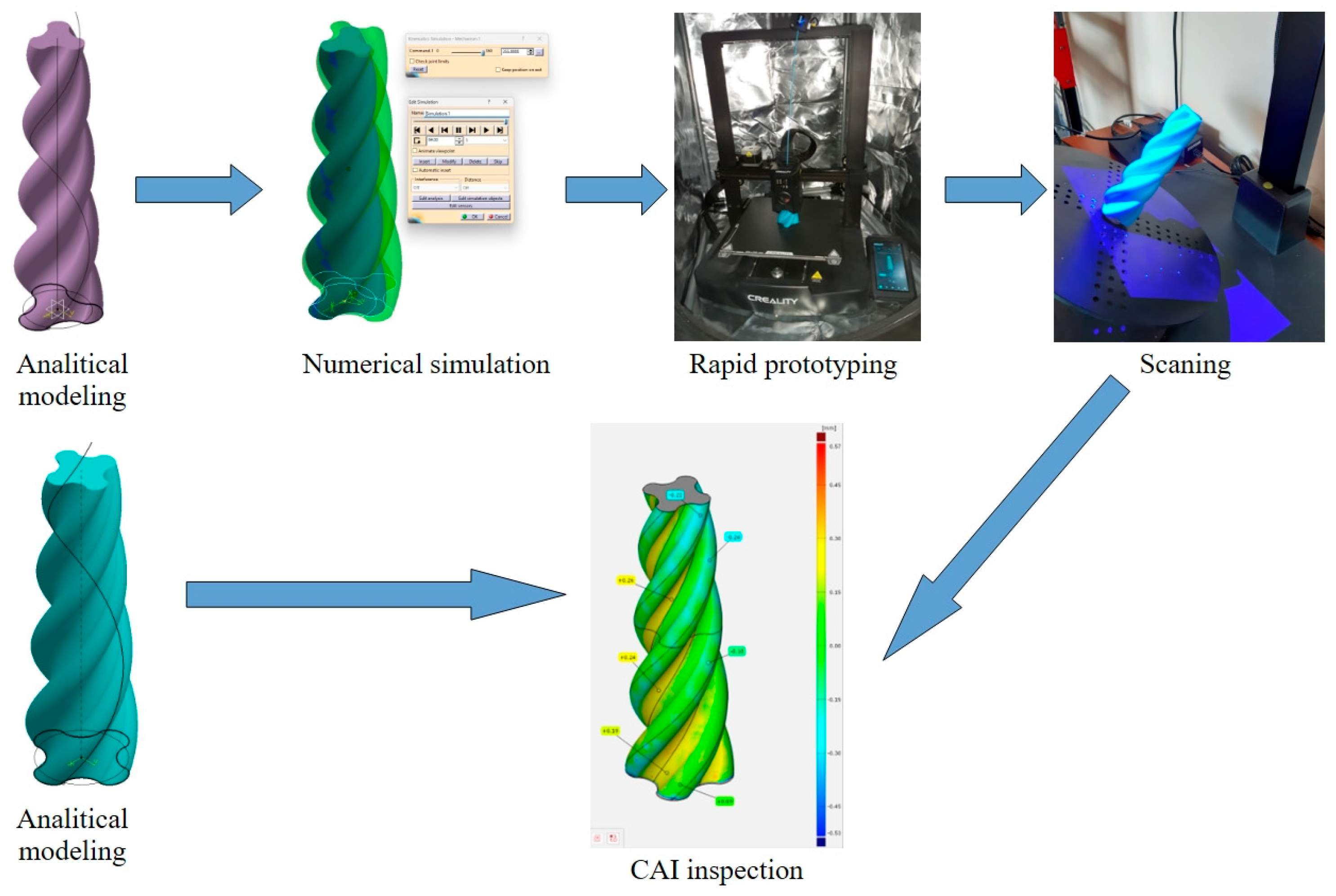
The validation method can be summarized in the following steps: analytical modeling of the two rotors → numerical simulation of the movement of the inner rotor → materialization through rapid prototyping of the volume swept by the rotor during its movement → verification of the result by comparing the swept volume with the analytical model of the outer rotor.
For the fabrication of the physical model, the fused filament fabrication (FFF) rapid prototyping method was used, employing a Creality Ender 3 V3 KE 3D printer, manufactured by Shenzhen Creality 3D Technology Co., Ltd, in Shenzen, China. A 0.4 mm nozzle was used, and the material was PLA, PolyTera brand, which allows for printing speeds between 30 and 70 mm/s and deposition temperatures between 190 and 230 °C to be obtained.
3. Analytical Representation of the Active Surfaces of Rotors
In order to model the relative kinematics of the two rotors, several aspects must be considered.
To obtain the analytical model of each of the rotors of the helical compressor, the process begins from the profile in a plane normal to the axis of the considered rotor.
In what follows, for each of the compressor rotors, we shall use the following reference systems [
21].
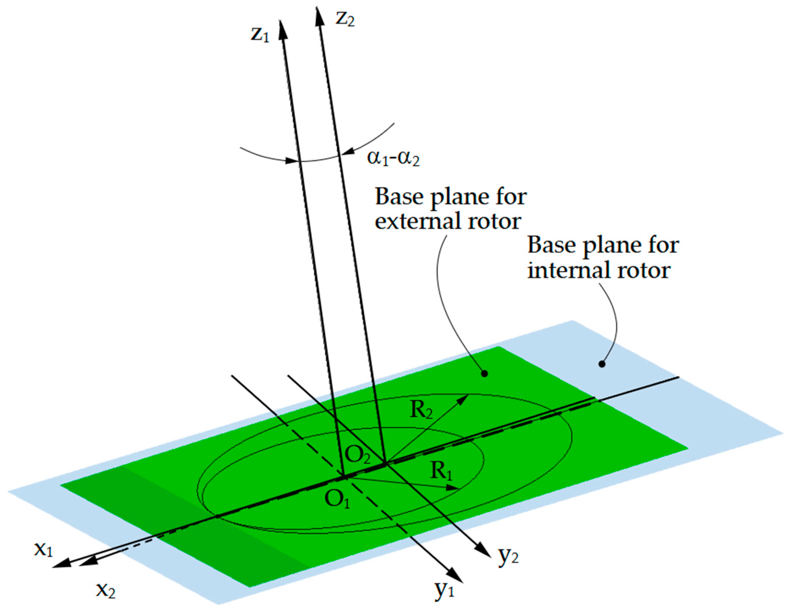
A reference frame denoted as x1y1z1 is joined to the internal rotor, with its origin located at the center of the rotor’s pitch circle. It is important to note that the rolling motion between the two conjugate centrodes, associated with the conical worm profiles, remains identical in planes normal to each worm’s rotation axis. However, the pitch radius varies depending on the position of the respective plane along the worm axis. In the following, the plane corresponding to z1 = 0 is referred to as the base plane of the internal rotor.
A second reference system, denoted x2y2z2, is fixed to the external rotor, with its origin in the center of the pitch circle of the outer rotor. By analogy with the previously presented reference system, the plane corresponding to coordinate z2 = 0 will be referred to as “the base plane” of the external rotor.
Unlike the classical case of conjugate enveloping profiles, where contact between the two profiles occurs at a single point, in conical helical compressors, as in gerotor pumps, contact must occur simultaneously at a minimum of two points on the profiles in order to ensure that the working fluid compression chambers are sealed.
This condition implies that the optimal rotor profile consists of lobes shaped by cycloidal arcs.
In practice, each of these profiles is a closed curve composed of a succession of hypocycloidal and epicycloidal arcs.
Moreover, the external rotor features one more lobe than the internal rotor.
This requirement imposes that the ratio between the pitch radii of the two centrodes respects the following relation [
21]:
where R
1 denotes the pitch circle radius, in mm, of the internal rotor, R
2 is the pitch circle radius, in mm, of the external rotor, Z represents the number of lobes for the internal rotor, Z + 1 is the number of lobes for the external rotor, and i represents the transmission ratio.
Each lobe of the internal rotor corresponds to an angular arc
on the base circle. This observation allows for the calculation of the rolling circle radius, r
1, which is needed to generate an integer number of lobes, Z [
21]:
Similarly, considering that Z + 1 lobes are formed on the base circle of the external rotor, and taking into account that the number of lobes is an integer, Z + 1, the rolling circle radius that generates the cycloidal profile of the external rotor will be as follows [
21]:
From Equations (1) to (3), it can be seen that r1 = r2; in what follows, the radius of the rolling circle will be denoted as r.
A final observation regarding the kinematics of the rotors refers to the fact that the helical parameters defining the helical surfaces of the rotors must satisfy the following condition [
21]:
where p
e1 is the helical parameter of the internal rotor and p
e2 is the helical parameter of the external rotor.
3.1. The Analytical Model of the Internal Rotor
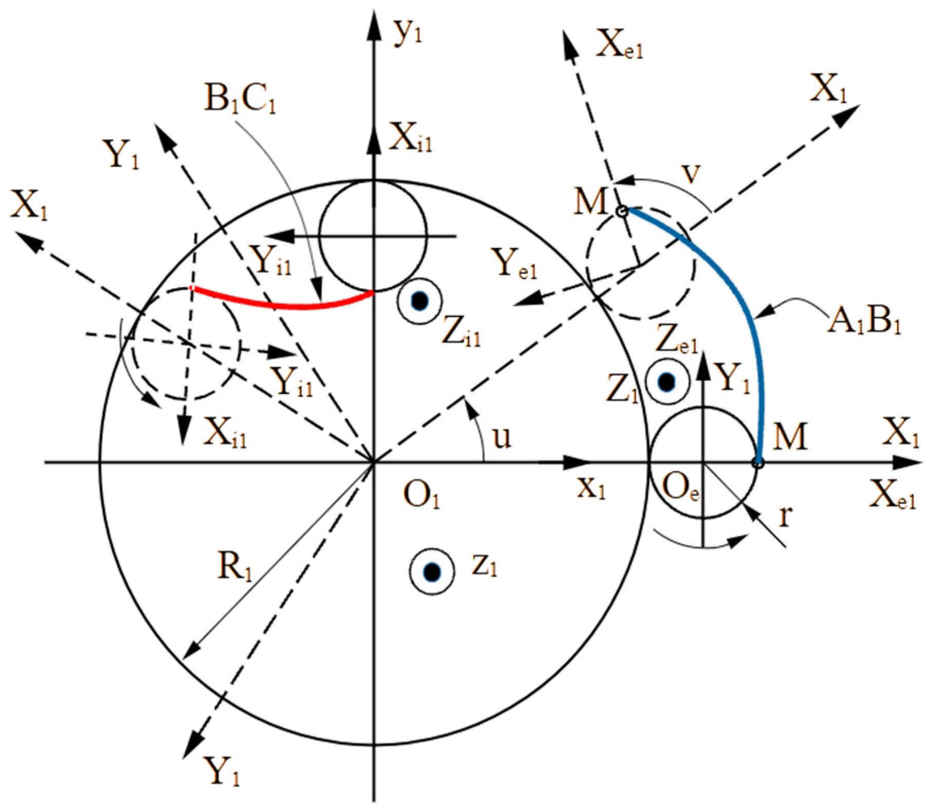
In order to determine the cross-sectional profile of the internal rotor, the following reference frame is used [
21]:
The x1y1z1 system, which, as previously shown, is fixed to the internal rotor, has its origin at the center of the rotor’s pitch circle, and the z1 axis coincides with the rotor axis.
The X
1Y
1Z
1 system, a moving reference system, has its X
1 axis defined by the points O
1 and O
e (see
Figure 1). The Z
1 axis of this system is parallel to the z
1 axis.
The X
e1Y
e1Z
e1 system, moving, is fixed to the rolling circle that generates the external lobe
(see
Figure 1).
The X
i1Y
i1Z
i1 system, moving, is fixed to the rolling circle that generates the internal lobe
(see
Figure 1).
Figure 1 illustrates the reference frames attached to the two rolling circles: shown with solid lines in their initial positions and with dashed lines in intermediate positions during the rolling motion.
If u denotes the rotation angle of the X
1Y
1Z
1 system regarding the fixed x
1y
1z
1 system, and v denotes the rotation angle of the X
e1Y
e1Z
e1 system regarding the X
1Y
1Z
1 system, rotational motions are established between the two moving systems:
resulting in the following:
If it is denoted by
the matrices are formed with the coordinates of a current point in the various reference systems used, and with
the rotation (ω) and translation (
A) matrices are formed between any two systems; then, considering that the X
e1Y
e1Z
e1 system rotates relative to the X
1Y
1Z
1 system and, at the same time, rotates about its own Z
e1 axis, the coordinate transformation between the X
e1Y
e1Z
e1 and x
1y
1z
1 systems can be written in the following form:
in this particular case, the translation matrix
A has the following form:
By expanding Equation (9) and taking into account (6), the equations of the hypocycloidal arc
are obtained (see also
Figure 1):
A similar procedure is applied for the hypocycloidal arc
, noting that in this case, the translation matrix
A is as follows:
The following equations are obtained:
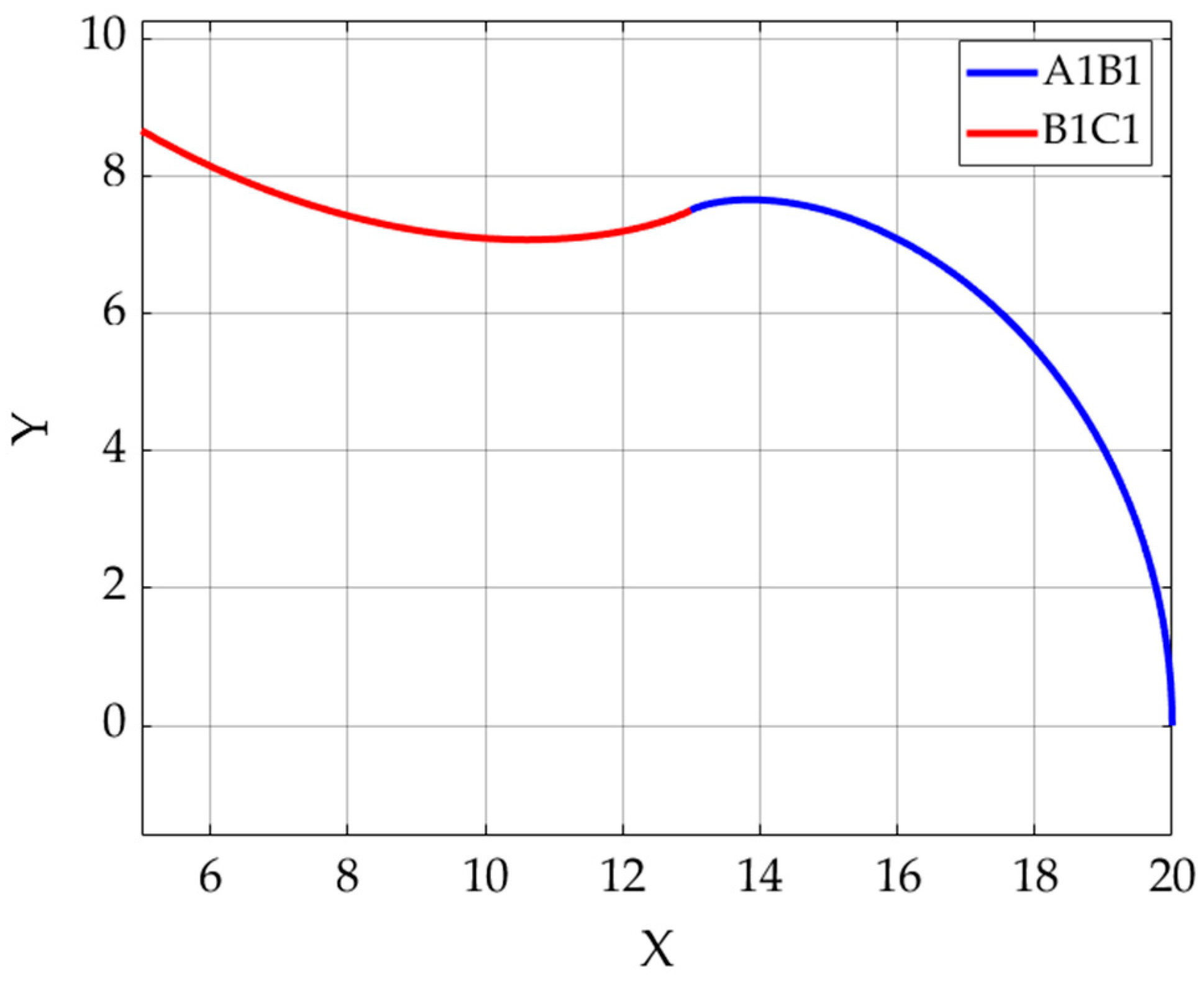
Table 1 presents the numerical values used in the design of the two rotors.
In this paper, the case of a compressor with Z = 3 lobes for the internal rotor was considered, with the values R
1 = 15 mm and r = 2.5 mm.
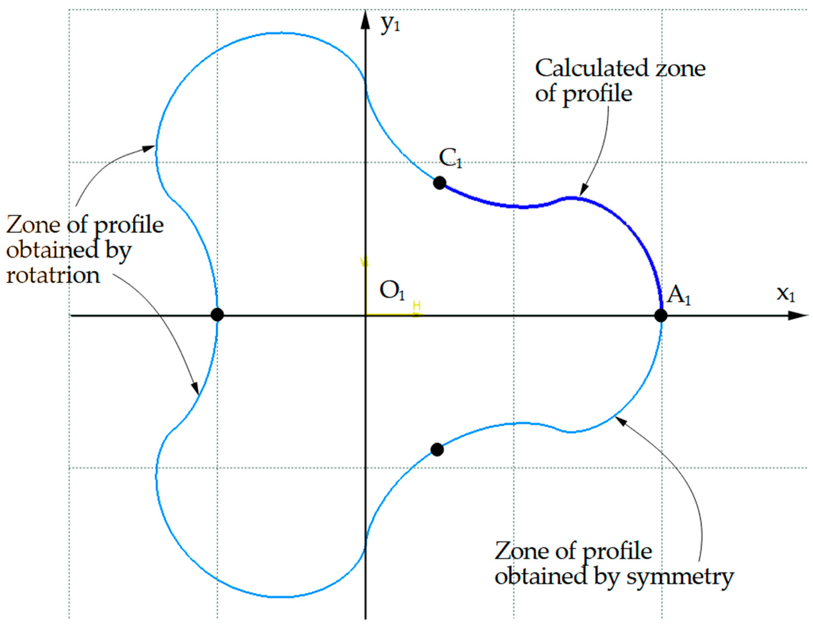
Figure 2 shows the profile of this rotor in the base plane, with the arc
represented in blue and the arc
represented in red.
The conical helical surface admits this profile as the generating curve and has a conical helical line as the guiding curve. In the present paper, a variable-pitch conical helical line passing through a point belonging to the profile centroid was considered.
3.2. Analytical Model of the External Rotor
To construct the cross-sectional profile of the external rotor—by analogy with the internal rotor—the following reference frames are employed [
21]:
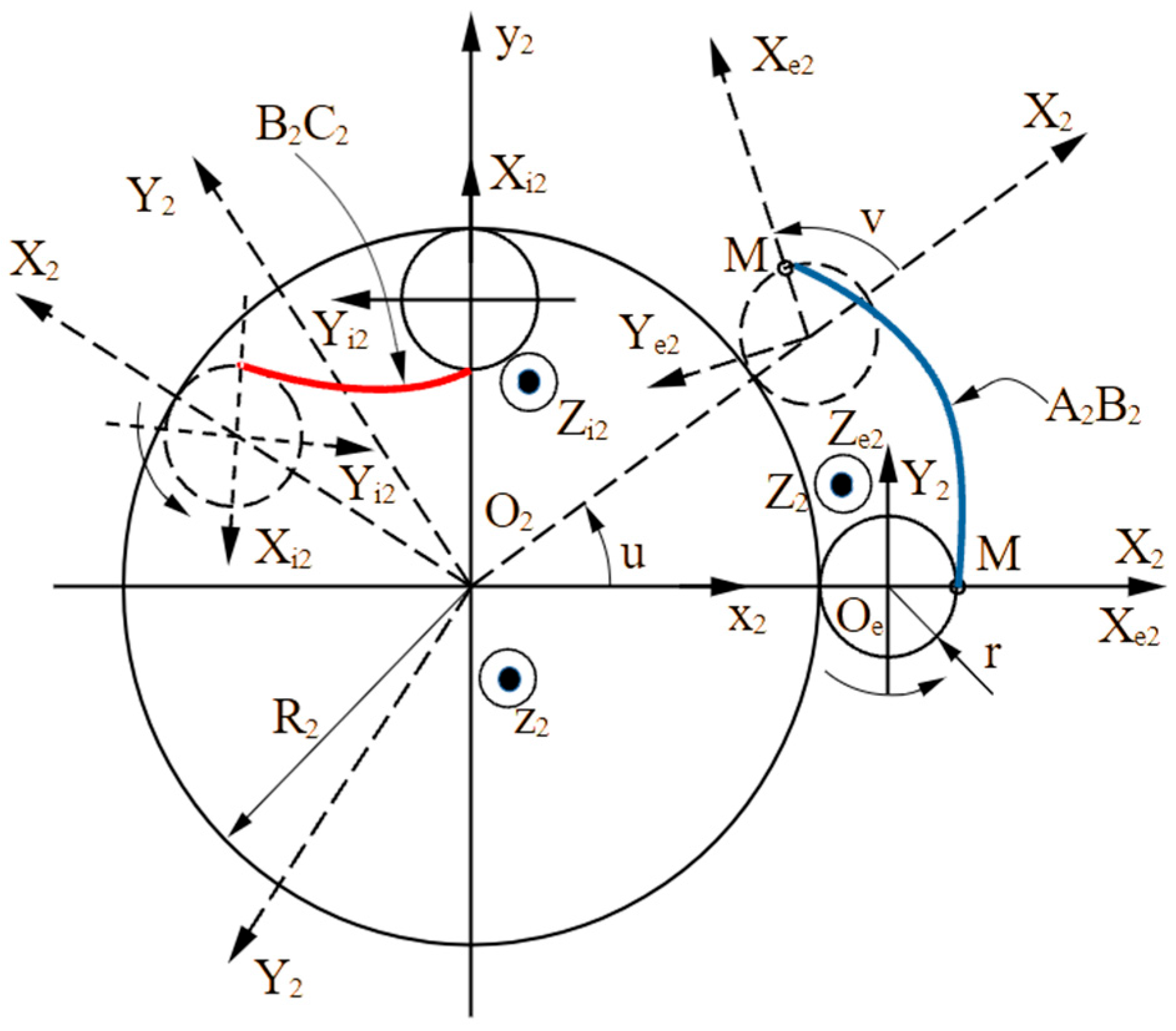
The reference frame x2y2z2 is fixed to the external rotor, with its origin at the center of the pitch circle and the z2 axis aligned with the rotor’s axis.
Additionally, a moving reference frame denoted as X
2Y
2Z
2 is defined, where the X
2 axis passes through points O
2 and O
e (see
Figure 3), and the Z
2 axis is parallel to z
2.
The X
e2Y
e2Z
e2 system, moving, is fixed to the rolling circle that generates the external lobe
(see
Figure 3).
The X
i2Y
i2Z
i2 system, moving, is fixed to the rolling circle that generates the internal lobe
(see
Figure 3).
Analogous to the internal rotor case, the angle u represents the rotation of the moving reference frame X
2Y
2Z
2 relative to the fixed frame x
2y
2z
2, while the angle v denotes the rotation of the X
e2Y
e2Z
e2 frame with respect to X
2Y
2Z
2. These rotational motions define the relationship between the two moving reference systems.
Resulting in the following equation:
If they are denoted with
the matrices formed with the coordinates of a current point in the various reference systems used, and taking into account the notations in Equation (8), yield the coordinate transformation between the X
e2Y
e2Z
e2 and x
2y
2z
2 systems in the following form:
where in this particular case, the translation matrix
A has the following form:
By expanding Equation (17) and taking into account (15), the equations of the hypocycloidal arc
are obtained (see also
Figure 3):
A similar procedure is applied for the hypocycloidal arc
, noting that in this case, the translation matrix
A is as follows:
The following equations are obtained:
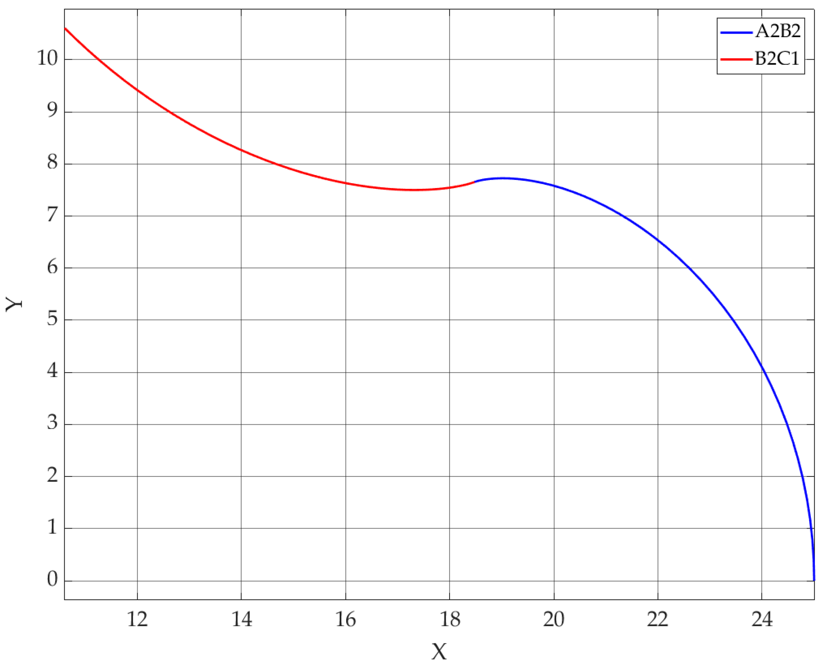
In this study, the case of a compressor with Z = 4 lobes for the external rotor was considered, with the values R
2 = 40 mm and r = 2.5 mm.
Figure 4 shows the profile of this rotor in the base plane.
As with the internal rotor, the conical helical surface of the external rotor admits this profile as the generating curve and has a conical helical line as the guiding curve, which passes through a point belonging to the profile’s centrode.
4. Numerical Modeling of the Relative Kinematics of the Rotors in a Helical Compressor
Numerical modeling of the kinematics of the two rotors in CATIA involves modeling the rotors as part-type elements and subsequently inserting them into an assembly. In addition to the two reference frames presented, it is necessary to model a third, fixed element that serves to establish the relative position of the moving elements. In the physical assembly represented by the helical compressor, this element is the compressor casing, which ensures the correct positioning of the moving parts.
For the creation of the models in CATIA, the following numerical values were used:
The number of lobes of the two rotors: Z = 3, Z + 1 = 4;
R1 = 15 mm, the pitch circle radius of the internal rotor; R2 = 20 mm, the pitch circle radius of the external rotor; and r = 2.5 mm, the rolling circle radius;
Pitch of the internal rotor helix in the base plane, pi1 = 120 mm. The helix pitch is variable, decreasing from the mentioned value to pi2 = 60 mm after four rotations;
Pitch of the external rotor helix in the base plane, pe1 = 160 mm, decreasing to pe2 = 80 mm after three rotations;
Semi-apex angle of the internal rotor cone, α1 = 2°; semi-apex angle of the external rotor cone, α2 = 2.667°.
Using these numerical values, the elements described above are modeled.
To create the assembly, two reference systems are used: a moving system fixed to the internal rotor, x1y1z1, and a moving system fixed to the external rotor, x2y2z2.
The y1 and y2 axes of the two reference frames are parallel. The planes x1y1 and x2y2 form an angle of α1 − α2 = 0.667°, and the origins of the coordinate systems were selected such that the pitch circles in their respective base planes—with radii R1 = 15 mm and R2 = 20 mm—are tangent at a point representing the gear meshing pole.
4.1. Modeling of the Fixed Element
This file contains wireframe-type elements and serves to ensure the relative positioning of rotors.
The two reference frames and the component elements are shown in
Figure 5.
4.2. Internal Rotor Modeling
Modeling the internal rotor requires the calculation of its cross-sectional profile. The profiling can be performed in any mathematical computing program such as Matlab or Octave, or an Excel spreadsheet can be used.
The data used in the present study were calculated in Matlab 2018, using scripts specifically developed by the authors for each of the cycloidal lobes of the rotor.
For the calculation of the coordinates of the points on the epicycloidal arc , Equation (11) was used, and for the coordinates of the points on the hypocycloidal arc , Equation (13) was applied.
Subsequently, the coordinates of these points can be imported into CATIA to create the rotor’s transverse profile. After import, the points are placed in a “Geometrical Set”. From here, they can be used in the sketch that will generate the profile by using the “Project 3D Elements” command, which projects the imported points onto the sketch’s working plane. By drawing a spline curve through the projections of the points, the curve defining the rotor contour in a cross-section in the working plane is obtained.
It is worth mentioning that, due to the axial symmetry of the profile, it is not necessary to generate the spline for the entire profile, which would complicate the shape of the curve. It is sufficient to generate one curve for each semi-arc of the cycloid and then, using specific mirroring and rotation operations, generate the complete profile. Particular consideration should be given to the ends of the curve, which must overlap perfectly to produce a continuous and closed curve. Otherwise, when attempting to generate the solid representing the internal rotor, an error will occur because the defining spline curve is not continuous or closed.
The sketch of the profile is shown in
Figure 6.
The next steps are to generate the auxiliary geometric elements that will allow for the simulation of rolling, namely the rotor axis, the origin O1 of the x1y1z1 reference system, and the centroid of the internal rotor in the base plane, with a circle of radius R1.
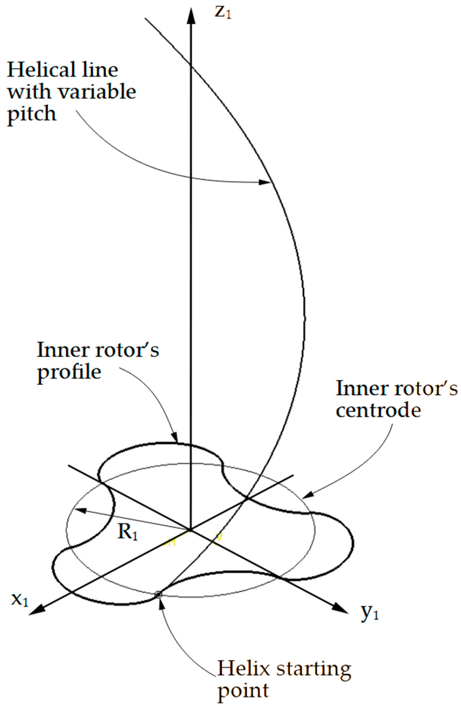
The final step is to construct the helical line that allows for the generation of the external rotor as a solid volume, using the “sweep” command. The point through which the conical helix passes is chosen as the intersection between the rotor centroid and the sketch of its cross-sectional profile.
The helix pitch is considered to decrease, starting from 120 mm at the first turn and reaching 60 mm after four turns.
A summary list of the commands used in CATIA V5R21 is presented below:
Volume => Volume sweep => Subtype: With two guide curves; profiles (sketch of the profile, see
Figure 6); guide curve 1 (helix line, see
Figure 7); guide curve 2 (axis of helix); anchoring type: two points; anchor point 1 (starting point of helix); anchor point 2 (starting point of axis); spine (axis of helix).
The geometric elements described above are shown in
Figure 7.
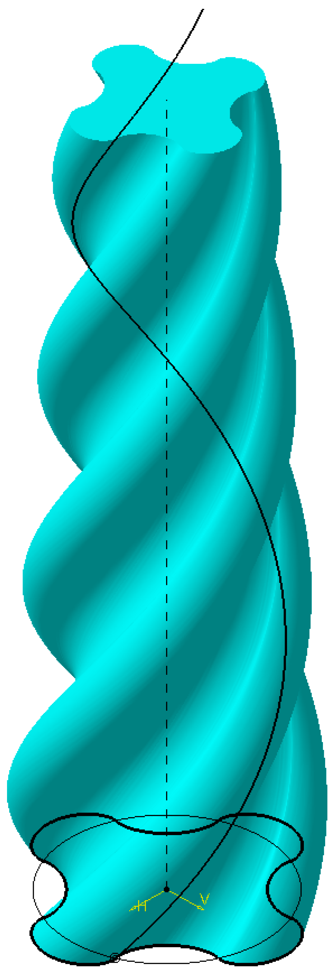
The final step is to create the volume of the internal rotor. For this, the “Volume Sweep” command is used, selecting the “With two guide curves” option. The two guide curves will be the rotor axis and the variable-pitch conical helix. Naturally, the generating profile will be the cross-sectional profile of the rotor. For the anchoring type, the “Two points” option is selected, with the two points being the origin of the reference system and the point through which the helix passes (the intersection between the profile sketch and the rotor centroid).
The other elements defining the volume, which are optional in this command, will be the “Spine”, for which the default option (the rotor axis) is retained, and the solid limiters, which can be chosen as the xy plane (Relimiter 1) and the end of the rotor axis (Relimiter 2). This construction allows for easy modification of the rotor length by simply changing the length of its axis.
The resulting volume is shown in
Figure 8.
4.3. Modeling of the External Rotor Cavity
In order to verify the profiling accuracy using the proposed method, it is necessary to create two independent models of the external rotor cavity.
The first model will be created similarly to the one presented previously, serving as a reference for profiling verification. The difference from the previous model is that the cross-sectional profile of the external rotor will be used, and a helix will be generated with a pitch starting at 160 mm for the first turn and decreasing to 80 mm after three turns. The apex angle of the cone of this helix is 2.667°, as indicated at the beginning of
Section 4.
Figure 9 shows the numerical model of the external rotor cavity obtained using the presented method.
The second model will be obtained by simulating the kinematics of the internal rotor in its relative motion with respect to the external rotor.
For this purpose, a new “Part” file must be created containing the elements necessary for generating the external rotor. These elements are entirely wireframe. First, the origin O2 of the x2y2z2 reference system, fixed to the external rotor, was materialized.
Next is the centroid of the external rotor, represented by a circle with radius R2 = 20 mm, supported on the xy plane. The final element is the axis of the external rotor.
With these three part files prepared, the assembly containing them is created. The process begins by inserting the fixed element into a “Product” file, to which the fixed element constraint is applied. The internal rotor part is then inserted, and a constraint is applied so that its axis coincides with the corresponding axis of the fixed element. A second constraint ensures coincidence between the xy plane of the internal rotor file and the P
1 plane of the fixed element (see
Figure 7).
The third element inserted is the external rotor part, to which constraints are applied to align its axis with the corresponding axis of the fixed element and to ensure coincidence between its xy plane and the xy plane of the fixed element.
To model the kinematics of the internal rotor, the “DMU Kinematics” module is used, creating a mechanism composed of the three elements. Since the relative motion of the internal rotor with respect to the external rotor must be simulated, the external rotor is considered the fixed element.
A gear-type pair is generated, with the internal rotor as one element and the external rotor as the other. The transmission ratio is equal to the ratio of the pitch circle radii of the two elements, i.e., i = 4/3. The simulation was performed for a complete rotation around the axis of the external rotor. A one-degree increment was used between two successive positions of the internal rotor.
After simulating the mechanism’s operation, the trajectory left by the internal rotor during its motion can be generated and saved as a “*.stp” file.
This file can then be materialized through rapid prototyping and scanned to compare the obtained shape with the theoretical shape of the external rotor cavity.
5. Verification of Profiling Accuracy
For the purpose of verifying the profiling accuracy, the numerical model of the external rotor cavity was produced using fused filament fabrication (FFF) technology. Subsequently, the resulting physical model was scanned using a video inspection system, and the result was compared with the analytically obtained CAD model.
5.1. Materialization of the Numerical Model of the Outer Rotor Cavity Through Rapid Prototyping
The printing was performed on a Creality Ender-3 V3 KE 3D printer, using PolyTerra PLA filament with a diameter of 1.75 mm and a 0.4 mm nozzle.
The chosen printing parameters were as follows: layer thickness 0.1 mm; infill density 15%; extrusion temperature 220 °C; and bed temperature 60 °C. The time required to produce the model was 2 h and 32 min.
Figure 10 shows an image taken during the printing process.
5.2. Scanning of the Printed Model
Using video scanning of the model, a three-dimensional numerical representation of the part is obtained, providing precise information regarding its shape and geometry. This information is used to evaluate the profiling accuracy by comparing it with a CAD model obtained through design.
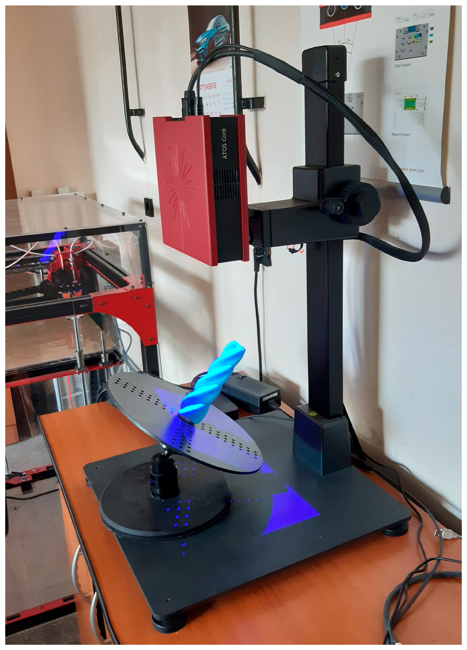
For 3D scanning, the ATOS Core 500 system, developed by GOM, was used, as shown in
Figure 11.
Using the aforementioned equipment, the part was scanned in detail, and the obtained 3D data were used to analyze its geometry. This allowed for a comparison to be made with the CAD model.
The scan data were processed using GOM Inspect 2019, a software solution tailored for reverse engineering and rapid prototyping. It enables the transformation of scanned surfaces into accurate 3D numerical models through advanced geometric reconstruction algorithms. To ensure complete digitization, multiple scans from various angles were performed and subsequently merged into a unified measurement series, resulting in a detailed and comprehensive digital representation of the components.
After completing the scanning process, polygonization was carried out, involving the alignment of all obtained images and the creation of the complete numerical model. The resulting file was saved in the “*.stl” format, enabling analysis with the dedicated GOM Inspect software.
5.3. Scanned Model Inspection
GOM Inspect software facilitates the evaluation of 3D video measurement data and the creation of precise geometric elements, enabling detailed analysis of the shape and dimensions of the scanned components.
Thus, for determining the dimensions of the external rotor cavity in the conical helical compressor, both the CAD model and the numerical model obtained through scanning were imported.
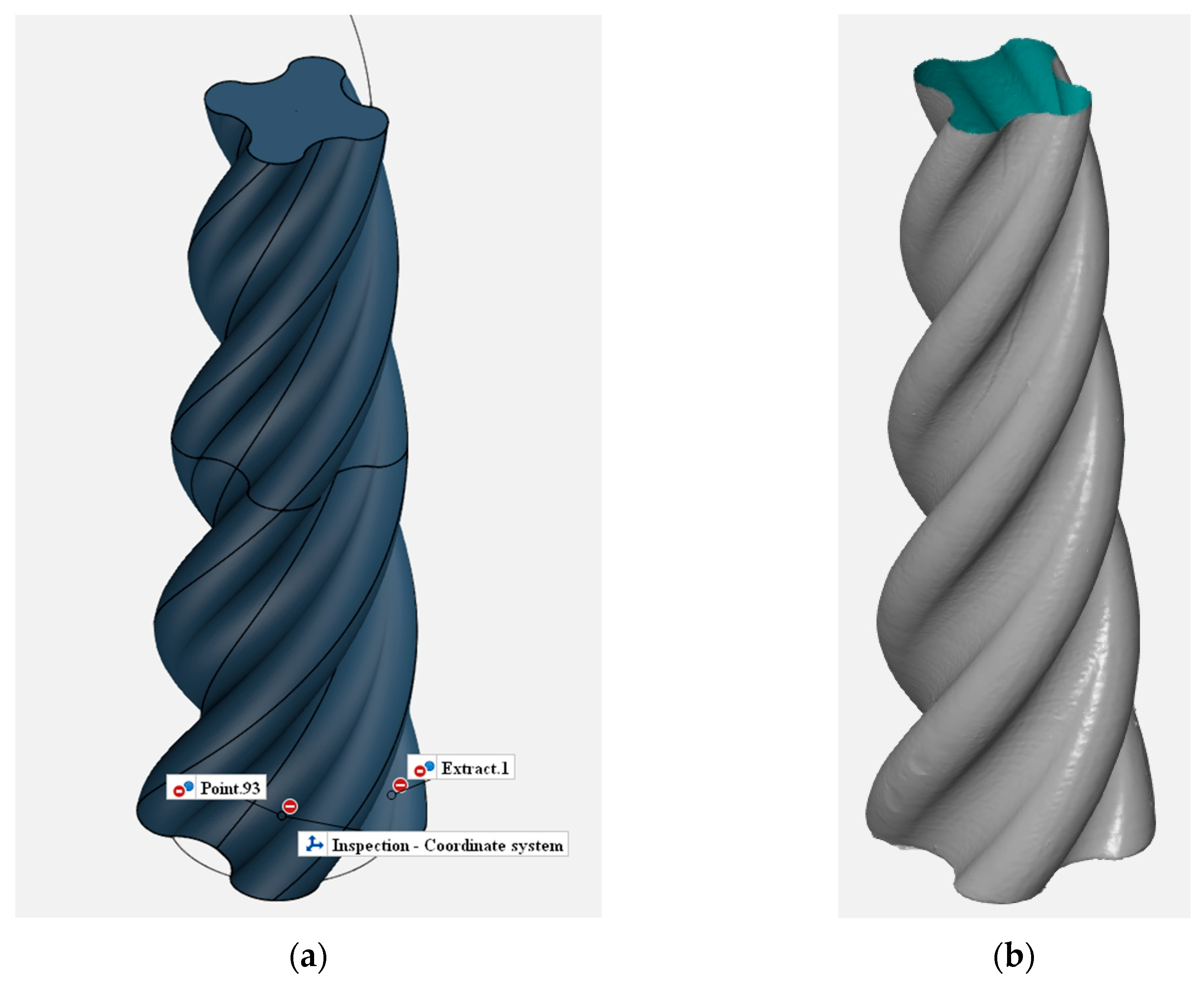
Figure 12a shows the CAD model imported into the computer-aided inspection (CAI) software GOM Inspect, while
Figure 12b shows the scanned numerical model imported into the same inspection program.
Immediately after import, a pre-alignment of the two models is required. During this operation, the GOM software identifies the position that ensures the best overlap of the models so that the distance from the scanned model surface to the CAD model surface is minimized.
The software offers a choice between three calculation times for the alignment. The longer the chosen time, the higher the accuracy of the alignment. In the present study, the option ensuring maximum precision was selected, corresponding to the “long” calculation time. The “pre-alignment” option with the longest calculation time was selected. These options resulted in an overall deviation of 0.13 mm.
After pre-alignment, the surface inspection can be performed, with the software comparing the surface of the scanned model with that of the CAD model. Based on this comparison, a graphical representation of the inspection result is generated, with the distance from the reference surface to the inspected surface indicated using a color code.
If the inspected surface exceeds the reference surface, the color used is red, while if it is below the reference surface, the color is blue. The greater the deviation, the more intense the color. Areas where the inspected surface coincides with the reference surface are colored green.
The software allows either model to be chosen as the reference surface via the options “Surface Comparison on CAD” or “Surface Comparison on Actual”. Depending on the model selected as the reference, the other automatically becomes the inspected model.
Figure 13 shows the inspection result in which the CAD surface was considered to be the reference surface.
GOM software allows for the selection of points where the deviation of the inspected surface from the reference surface is displayed. Using this feature,
Figure 13 shows deviations at several points where the largest discrepancies occur.
It is visible that the deviations fall within the allowable tolerances, which for this type of compressor are on the order of tenths of a millimeter. We considered a tolerance of ±0.3 mm to be acceptable.
The inspection window of the software also displays the legend of the color code used. This legend is presented on the left side of
Figure 13.
6. Discussion
From the graph of deviations of the actual surface relative to the theoretical one, it can be observed that the areas with positive deviations correspond to regions where the profile exhibits concavities (see also
Figure 13).
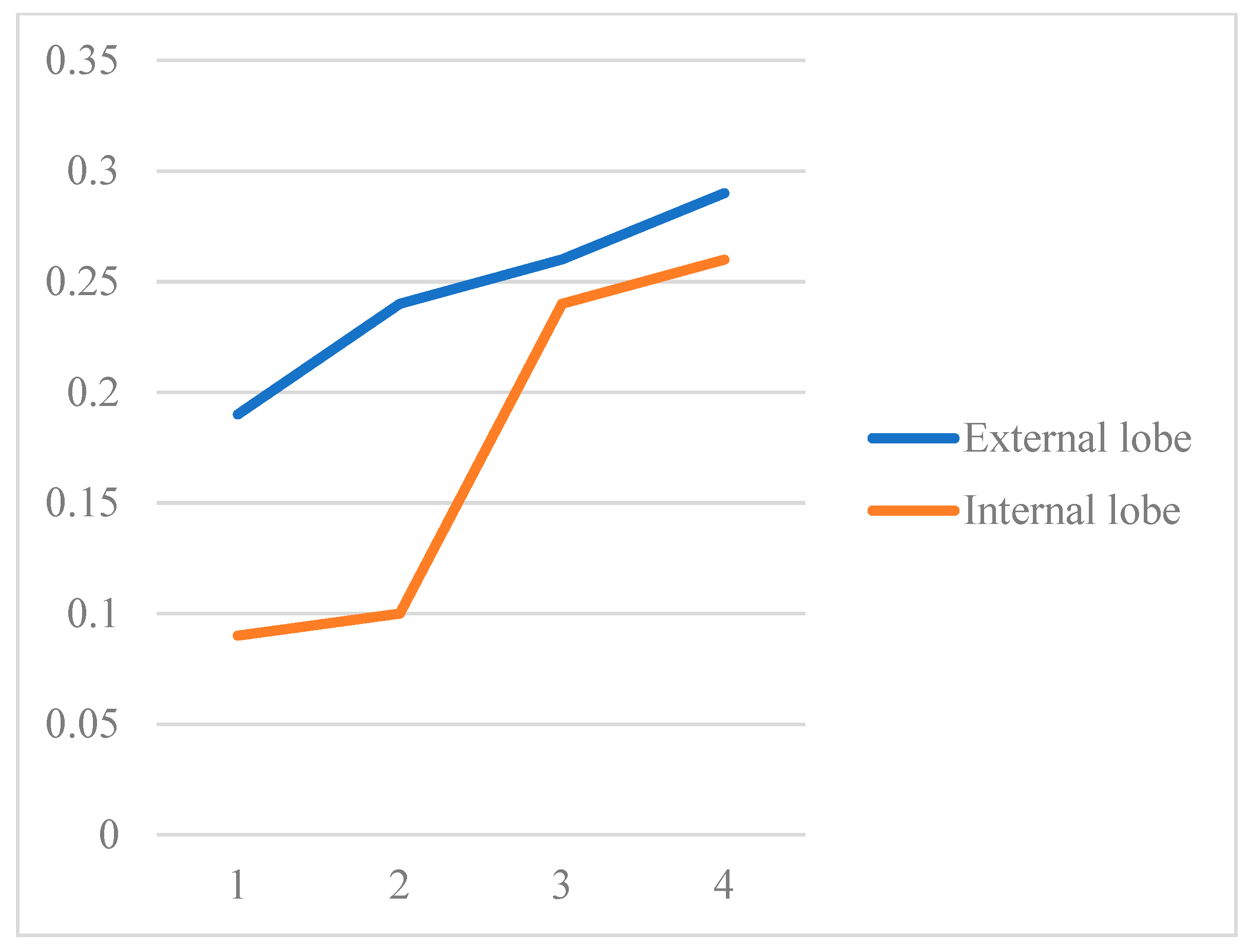
Furthermore, analysis of the deviation values shows that they tend to increase in absolute value towards the tip of the rotor, where the pitch decreases (see
Figure 14).
The results obtained show the deviation of the reference made by rapid prototyping from the numerical model generated by simulation.
It should be taken into account that the deviation of the physical object from the numerical model obtained by analytical calculation is larger, as it is the result of the accumulation of three main types of errors.
First, there are errors caused by the simulation process, which appear due to the limited number of steps with which the rotor movement is represented. A solution to reduce these errors is positioning with the smallest possible step during the movement simulation.
A second cause of errors is the additive manufacturing process, which through thermal shrinkage, layer overlaps, imprecision in the positioning of the print heads, etc., affects the precision of the object obtained.
Finally, there are measurement errors induced by the scanning equipment. Although present, these are the least of the three types of errors.
The method presented can be applied to any situation involving conjugated surfaces, for example, in profiling trochoidal pumps.
One of the obvious limitations of this method is that it can only be used if the moving surface is an encompassing surface. This means that reverse profiling cannot be performed, i.e., starting from the known shape of the external rotor surface (encompassing surface), it is not possible to determine the shape of the internal rotor surface (contained surface).
7. Conclusions
What follows are the original contributions of the present work:
1. Proposing a method for profiling the internal rotor of a conical screw compressor with variable pitch through the simulation of the external rotor’s kinematics. The design of this kind of helical surface, conical, with variable pitch, is particularly complicated, and the rigorous and efficient realization of this stage represents a technical challenge.
2. Verifying the kinematics of the internal rotor within a conical screw compressor.
Conducting an analysis of the influence of the helix angle on modeling accuracy and rotor contact, an aspect rarely addressed in the specialized literature.
3. Integrating an experimental validation procedure based on high-precision 3D printing and 3D video scanning (ATOS 500).
The validation method is presented in
Figure 15 and can be summarized in the following stages: analytical modeling → simulation of the movement → materialization through rapid prototyping → verification of the results.
Through these elements, this work addresses an insufficiently explored problem and provides a practical, experimentally validated solution for profiling conical screw rotors, with direct implications for the design and manufacturing of next-generation compressors.
