Article

Numerical Investigation of Fracture Behavior and Current-Carrying Capability Degradation in Bi2212/Ag Composite Superconducting Wires Subjected to Mechanical Loads Using Phase Field Method

College of Mechanics and Engineering Science, Hohai University, Nanjing 211100, China
*
Author to whom correspondence should be addressed.
Modelling 2025, 6(4), 119; https://doi.org/10.3390/modelling6040119
Submission received: 2 July 2025 / Revised: 24 September 2025 / Accepted: 28 September 2025 / Published: 1 October 2025

Abstract

Bi2Sr2CaCu2O8+x (Bi2212) high-temperature superconductor exhibits broad application prospects in strong magnetic fields, superconducting magnets, and power transmission due to its exceptional electrical properties. However, during practical applications, Bi2212 superconducting round wires are prone to mechanical loading effects, leading to crack propagation and degradation of superconducting performance, which severely compromises their reliability and service life. To elucidate the damage mechanisms under mechanical loading and their impact on critical current, this study establishes a two-dimensional model with existing cracks based on phase field fracture theory, simulating crack propagation behaviors under varying conditions. The results demonstrate that crack nucleation and propagation paths are predominantly governed by stress concentration zones. The transition zone width of cracks is controlled by the phase field length scale parameter. By incorporating electric fields into the phase field model, coupled mechanical-electrical simulations reveal that post-crack penetration causes significant current shunting, resulting in a marked decline in current density. The research quantitatively explains the mechanism of critical current degradation in Bi2212 round wires under tensile strain from a mechanical perspective.

1. Introduction

Bi2Sr2CaCu2O8+x (Bi2212) superconducting materials, as a class of ceramic brittle materials, are highly susceptible to fracture under mechanical loading. Current research on their mechano-electrical sensitivity primarily focuses on two aspects: (1) enhancing the critical current density of wires, and (2) improving mechanical strength and structural stability to mitigate critical current degradation induced by mechanical stress.
Shin et al. [1] estimated Young’s modulus, thermal residual strain, intrinsic fracture strain, and room-temperature thermal expansion coefficient of superconducting filaments in Bi2212/Ag/AgMg composite wires through combined tensile testing, X-ray diffraction, and thermodynamic analysis, providing fundamental parameters for coupled mechanical-electrical calculations. Katagiri et al. [2] experimentally investigated critical current variations in Bi2212 wires under tensile strain, introducing the critical load concept to define the strain threshold beyond which rapid critical current degradation occurs. Mao et al. [3] demonstrated strain-dependent elastic modulus reduction in Bi2212 under increasing tensile loads. Godeke et al. [4] and Bjoerstad et al. [5] revealed that denser and more homogeneous filament structures yield broader reversible strain ranges for critical current preservation. Cheggour [6] utilized SEM micrographs to show longitudinal cross-sections post-tensile testing: dense regions remained crack-free, while porous zones exhibited multiple cracks penetrating Bi2212 filaments, confirming porosity–crack correlation. Axial loading studies further documented buckling, kinking, and fracture behaviors, with complete critical current-strain curves established.
The control of bubble defects in Bi2212 round wires has been a focal point for research teams. Li et al. [7] achieved a critical current density of 7600 A/mm2 at 4.2 K under self-field conditions by optimizing the powder composition ratio and refining raw material processing to reduce porosity. Shen et al. [8] further employed high-pressure remelting technology to treat Bi2212 filaments, effectively eliminating internal bubble defects and significantly enhancing the critical current density. Han et al. [9] demonstrated that the rolling process could improve filament compactness in Bi2212 round wires, leading to a notable increase in critical current density. The superconducting Bi2212 round wires exhibit significant electromechanical sensitivity, where their critical current undergoes severe degradation under varying axial loads. Wang et al. [10] investigated the influence of compressive loading on the critical current of Bi2212 wires by analyzing micro-buckling of filaments. Treating Bi2212 filaments as a unidirectional filament-reinforced composite and accounting for the effects of inclusions, the study derived the micro-buckling wavelength based on a two-dimensional model. Additionally, the finite element method was employed to analyze the critical strain in filaments containing filament bridge structures.
Liu et al. [11] correlated crack-induced current distribution changes with applied strain in Bi2212 round wires. Yang et al. [12] developed a variational principle-FEM hybrid method for 2D coupled problems. Lu et al. [13] found that large bubbles increase bridge strain, preferentially damaging central filaments over edge ones. Peng et al. [14] applied fiber-composite bridging models to predict wire strength, analyzing volume fraction, modulus, and interfacial shear effects. Wang et al. [15] reconstructed complex microstructures to study multi-physics coupling, while Jiang et al. [16] employed fractal models to examine Ag-matrix interface effects on quench behavior.
In recent years, numerical simulation methods for material fracture behavior have undergone significant development, resulting in diverse theoretical and technical approaches for modeling crack initiation and propagation. These methods can be broadly categorized into two classes: discontinuous methods and continuous methods. (1) Discontinuous methods, which explicitly introduce strong discontinuities into the displacement field to describe crack propagation. Representative techniques include the Generalized Finite Element Method (GFEM) [17,18], Virtual Node Method [19,20], and the Extended Finite Element Method (XFEM) [21,22]. These methods require a specific crack topology description and tracking techniques. Additional criteria to characterize crack branching and interactions include (2) continuous methods, which avoid introducing discontinuities entirely. Common approaches encompass Gradient Damage Models [23,24,25], phase field models [26,27,28], and Peridynamics (nonlocal methods) [29]. Key terminology standardization is as follows: strong discontinuity (validated by the fracture mechanics literature), crack topology description (consistent with computational mechanics terminology), and branching (standard in fracture dynamics). Discontinuous methods are computationally intensive but provide explicit crack path visualization.
Recent applications in brittle fracture [30,31,32] include Han et al. [33], who incorporated plastic driving forces and degraded fracture toughness for quasi-brittle materials, and Teichtmeister et al. [34], who derived anisotropic crack driving forces via structural tensors. Wu’s team [35,36,37,38] proposed a cohesive phase field model integrating fracture strength, validated in multi-physics simulations. Extensions to ductile fracture [39,40] and anisotropic materials [41] have been achieved, with Kuhn-Müller [42] modeling crack-affected thermal conduction.
This work establishes a 2D phase field model with pre-existing cracks to simulate crack propagation in Bi2212 wires under mechanical loading and investigate the current degradation mechanisms during fracture. This paper aims to reveal the damage evolution law and critical current degradation mechanism of superconducting round wires under mechanical loads. By incorporating the phase field damage variable into the superconducting constitutive equation, the suppression mechanism of critical current under external load is revealed. This paper is organized as follows. We briefly introduce the basic theory of the phase field model in Section 2. After that, we introduce the effect of crack propagation on critical current in Section 3. Additionally, we present the numerical implementation of the phase field model in COMSOL (version 6.2) in detail and display the results of some examples. Finally, relevant conclusions are summarized and discussed in Section 4.

2. Phase Field Model for Crack Propagation in Bi2212 Round Wires Under Tensile Load

2.1. Basic Equations of Phase Field Model

The establishment of the phase field model for brittle fracture originates from the variational principle proposed by Francfort and Marigo [43]. This principle asserts that the total potential energy of brittle materials comprises three components:
W = Ω ψ ε ( u ) d Ω + Γ G c d S Ω   b u d Ω Ω f u d Ω
in which the first term is the strain energy of the material, and ψ ε ( u ) is the strain energy density. The second term is the fracture energy and G c is the critical energy release rate. The last two terms are the external potential energy, in which f and b are the boundary traction and body force, respectively. The strain energy density is defined as
ψ ε ( u ) = 1 2 λ ε i i 2 + μ ε i j ε i j
where ε is the strain tensor, λ is the Lamé constant, and μ is the shear modulus. The phase field method is a variational fracture mechanics approach based on the energy minimization principle, which describes crack evolution through a continuous phase field variable ϕ ( x ) . Here, ϕ = 0 represents the intact region (no cracks), ϕ = 1 denotes the fully fractured region, and 0 < ϕ < 1 corresponds to the crack transition zone. The fracture surface energy can be expressed as follows:
Γ G c d S = Ω G c ϕ 2 2 l 0 + l 0 2 ( ϕ ) 2 d Ω
in which l 0 is the length scale parameter, which controls the width of the transition zone where the phase field order parameter varies from 0 to 1, serving as a parameter that reflects the crack width.
To accurately simulate brittle fracture processes and ensure crack propagation occurs solely under tensile loading, the elastic strain energy must be decomposed into tensile and compressive components. This decomposition effectively prevents unrealistic crack growth under compressive loads, ensuring that the phase field evolution is strictly driven by tensile strain energy density, while the compressive energy component remains inactive in the fracture process. Specifically, the strain tensor can be decomposed into tensile and compressive parts, typically expressed as
ε + = a = 1 3 ε a + n a n a ε = a = 1 3 ε a n a n a
where ε + and ε are tension and compression strain tensor, respectively, and ε a is the principal strain, n a is the vector of the corresponding principal direction and · ± = · ± · / 2 [28]. Furthermore, the strain energy density can be decomposed as
ψ + ( ε ) = λ 2 t r ε + 2 + μ t r ε + 2 ψ ( ε ) = λ 2 t r ε 2 + μ t r ε 2
The strain energy density for damaged materials in Equation (2) can thus be obtained as
ψ ε ( u ) = g ( ϕ ) ψ ε + ( u ) + ψ ε ( u )
Here, the energy degradation function g ( ϕ ) acts as a bridge connecting the intact region ( ϕ = 0 ) and the fully fractured region ( ϕ = 1 ). The selection must satisfy the conditions g ( 0 ) = 1 ,   g ( 1 ) = 0 and g ( 1 ) = 0 , which ensures that in the intact region ( ϕ = 0 ), the elastic strain energy remains unchanged. In the fully fractured region ( ϕ = 0 ), the elastic strain energy is fully released. In the transition region ( 0 < ϕ < 1 ) between intact and fully fractured zones, the material’s elastic stiffness gradually degrades, and the elastic strain energy progressively decreases with crack evolution but has not yet completely dissipated.
Furthermore, to prevent the tensile component of the elastic strain energy density from fully degrading to zero when the fracture order parameter ϕ approaches 1 (which would induce numerical singularities), a stabilization parameter k ( 0 < k 1 ) is introduced in the model. For numerical stability, physical rationality, and its extensively validated engineering applicability, this paper adopts a quadratic energy degradation function, expressed as
g ( ϕ ) = ( 1 ϕ ) 2 + k , k = 1 × 10 6
The total potential energy of the system can be rewritten as follows:
W u ,   ϕ = Ω ( 1 ϕ ) 2 + k ψ ε + ( u ) + ψ ε ( u ) d Ω + Ω G c ϕ 2 2 l 0 + l 0 2 ϕ x i 2 Ω b u d Ω Ω h f u d S
By varying the displacement field and phase field separately, the governing equation of the system can be obtained as follows:
σ i j x j + b i = 0 2 l 0 ψ ε + G c + 1 ϕ l 0 2 2 ϕ x i 2 = 2 l 0 ψ ε + G c
in which σ i j is the Cauchy stress tensor, whose expression is
σ = ( 1 ϕ ) 2 + k λ t r ( ε ) + I + 2 μ ε + + λ t r ( ε ) I + 2 μ ε
in which I is the unit tensor. In order to ensure the irreversibility of the crack evolution process, that is, once the crack is formed, it will not heal during the unloading process, we introduce a historical variable H ( x , t ) to record the maximum tensile strain energy experienced by a given position x in the loading history:
H ( x , t ) = max s ( 0 , t ) ψ ε + ( ε ( x , s ) )
Then, rewrite the control equation as
σ i j x j + b i = 0 2 l 0 H G c + 1 ϕ l 0 2 2 ϕ x i 2 = 2 l 0 H G c
The boundary conditions are
σ i j m j = f Ω h i ϕ x i = 0 Ω ϕ = 1 Γ

2.2. Numerical Examples

Solving the control Equation (12) along with the boundary condition Equation (13), the strain field and damage field of a superconducting round wire subjected to a tensile stress can be obtained. However, the analytical solution of Equation (12) is generally difficult to obtain. Numerical methods include the finite element method, the finite difference method, the spectral method, etc. The finite element method is widely used due to its ability to handle complex boundaries. In this paper, the finite element method is employed to fully exploit the multi-physics coupling capabilities of COMSOL Multiphysics for the numerical simulations. The stress and damage field are solved via the Solid Mechanics Module, whereas the current density is solved via the Electric Current Module in COMSOL Multiphysics. The coupling between the electrical field and the stress field is implemented via the phase field variable. In all modules, the differential equations are all discretized using linear shape functions. The option for geometric nonlinearity is not turned on. We used a fully coupled solver and employed the Newton–Raphson iteration for nonlinear iterative calculations. The Newton–Raphson iteration tolerance is set to 0.0055. The Anderson acceleration was chosen to stabilize and accelerate solutions. All simulations are conducted on a high-performance computing platform with an Intel(R) Core(TM) i7-14650HX CPU @ 2.20 GHz and 32 GB of RAM (Nanjing, China), ensuring both efficiency and accuracy, and providing a solid foundation for subsequent in-depth studies of crack propagation and failure in superconducting round wires.
Due to the limitation of computational scale, we established a two-dimensional model based on the longitudinal section of a superconducting circular wire for calculation. This simplification slightly overestimates the volume fraction of the superconducting part, which we will analyze again in the results and discussion sections. The numerical model studied in this article is based on a 37 × 18 cross-section superconducting core for a two-dimensional simulation. Although the actual Bi2212 round wire is not completely centrosymmetric, in the two-dimensional case, a smaller number of core wires does not significantly affect the simulation results of the finite element model. Therefore, in order to simplify the modeling process, this article assumes that it is a symmetrical structure. In order to save calculation time and space while ensuring calculation accuracy, this chapter only selects six core wires on the symmetrical axis boundary of 1/2 cross-section as the research object. Based on the above parameter information, as shown in Figure 1, a two-dimensional finite element model of the longitudinal section of Bi2212 was established, and the geometric parameters of the model are listed in Table 1.
In this study, regarding the material parameters of the two-dimensional finite element model, the elastic modulus and yield stress of Ag and AgMg alloys are usually temperature dependent [44,45]. However, in order to simplify the finite element model and focus on other key factors, this study did not consider the influence of temperature on these mechanical parameters. Therefore, the elastic modulus and yield stress of Ag and AgMg alloys are selected as constant values, which are based on the relevant literature and experimental data and conform to the material properties under typical working conditions. On the other hand, the elastic modulus of Bi2212 is assumed to be temperature independent [46]. The rationality of this hypothesis lies in the fact that experimental studies have shown that the change in elastic modulus of Bi2212 within the relevant temperature range is less than 5%, indicating its weak dependence on temperature. Therefore, treating it as a constant not only simplifies the calculation model but also does not significantly affect the accuracy of the simulation results. The specific material parameters are shown in Table 2.
After establishing a fracture phase field model for a two-dimensional Bi2212 superconducting circular wire, the crack propagation under tensile load was simulated. By analyzing the loading displacement and fracture phase field damage, the crack propagation is summarized, and the influence of phase field model parameters such as grid size, length scale parameters, and critical energy release rate on crack propagation behavior is discussed, laying the foundation for subsequent research on the effect of tensile crack propagation on the critical current of Bi2212 superconducting circular wire.
Conduct a finite element simulation analysis on the Bi2212 superconducting round wire with initial cracks. Firstly, in the finite element model, an initial crack with a length of 0.05 mm is preset at the bottom edge of the superconducting layer to study the propagation behavior of the crack under external loads. In terms of boundary conditions, a displacement load along the x-direction is applied to the left end of Bi2212, while constraining the vertical displacement to ensure reasonable mechanical constraints. In order to ensure the accuracy and numerical stability of the simulation results, the model adopts free triangular mesh division. The selection of grid size is directly influenced by the length scale parameters and adjusted accordingly according to different calculation conditions. The relevant physical parameters are listed in Table 3, and their values are adjusted appropriately according to different calculation requirements to ensure a reasonable simulation and convergence of the crack propagation process.
Due to the significant impact of mesh partitioning on the accuracy and stability of finite element models, this study conducted a systematic analysis by adjusting the maximum mesh size h max under fixed length scale parameters l 0 = 0.001 mm . In order to evaluate the influence of grid refinement on crack propagation simulation, four different grid sizes were selected for comparative study: h max = 2 l 0 , h max = 2 l 0 / 3 , h max = l 0 / 2 , h max = l 0 / 3 . The local mesh division is shown in Figure 2.
All the stress and strain obtained in this paper are nominal stress and nominal strain. The stress-strain curves under different grid sizes are shown in Figure 3. The results indicate that as the grid size increases, the stress peak of the phase field model gradually increases, while the crack propagation rate slightly decreases, but the overall difference is not significant. Based on the above analysis, while ensuring computational efficiency, this work will adopt grid partitioning criteria to effectively control energy dissipation errors caused by numerical diffusion and avoid the sharp increase in nonlinear computational costs caused by excessive refinement of the grid.
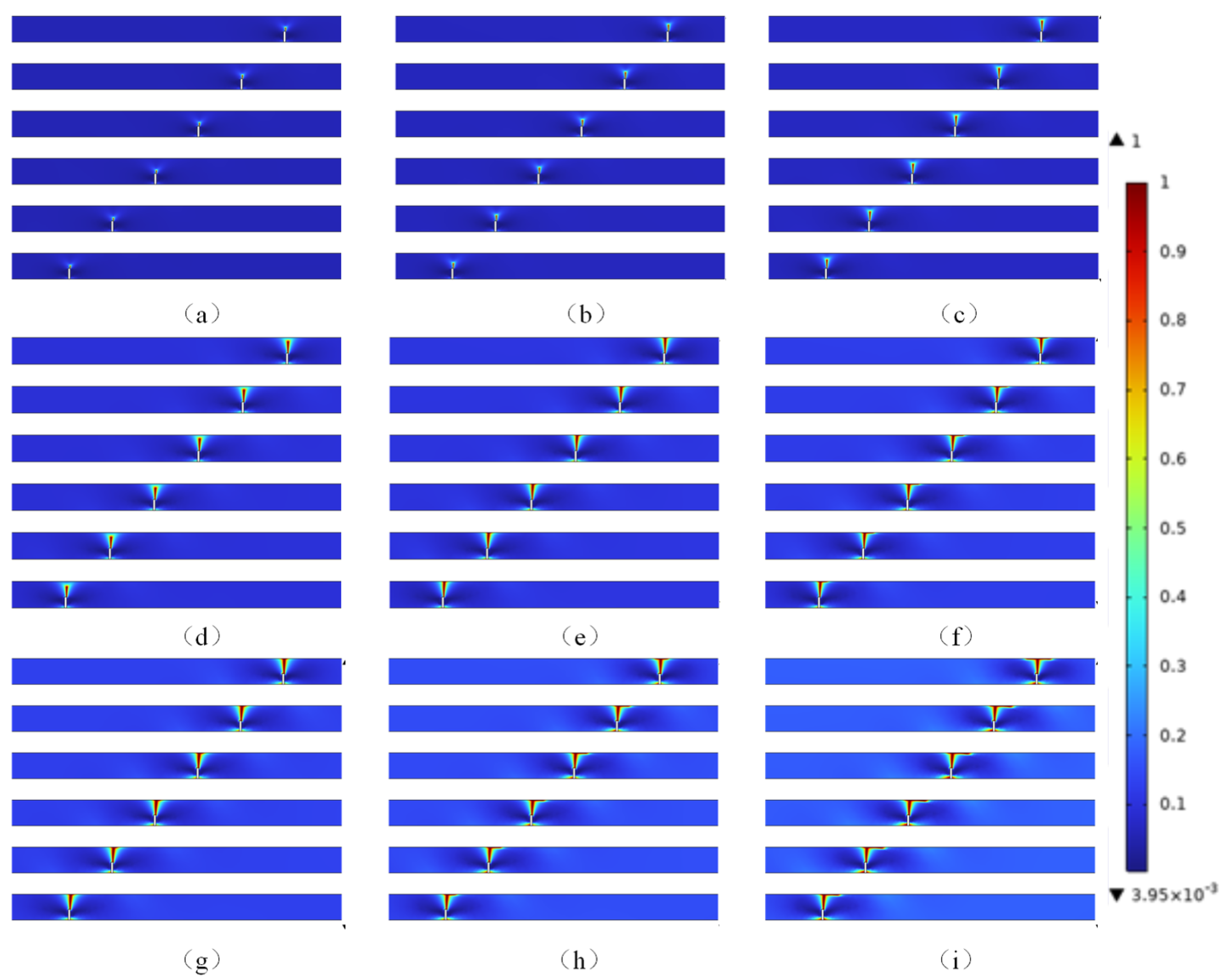
In order to investigate the influence of characteristic length scale parameters on the crack propagation behavior of the Bi2212 two-dimensional finite element model, we constructed three sets of phase field damage models with different length scale parameters for the condition of grid size set to h max = 2 l 0 / 3 , and numerically simulated the crack propagation process and final morphology. The uniform grid size eliminates the interference of grid effects on the results, ensuring consistency in computational accuracy and convergence. Through simulation analysis, the influence of length scale parameters on crack propagation paths and damage zone distribution was systematically explored. The final shape of crack propagation obtained from the simulation is shown in Figure 4.
The characteristic length parameter in the phase field model directly affects the crack propagation behavior, specifically by controlling the dispersion range of phase field variables, that is, the width of the damage zone, as shown in Figure 4. It reflects the regulatory effect of material microstructure on macroscopic crack behavior, such as grain size and defect distribution. For ceramic materials, l0 is usually taken at the micrometer level. The numerical simulation analysis of the finite element model shows that the characteristic length scale has a significant nonlinear regulatory effect on the crack propagation behavior. When l 0 = 0.001 mm, the width of the damage zone is narrow, and the resolution of the gradient field at the crack tip is high. Additionally, the crack propagation path is clear and exhibits sharp characteristics, and it stably extends along the direction of the maximum principal stress. As it increases to l 0 = 0.002 mm, the phase field diffusion effect strengthens, the width of the damage zone increases, and the crack tip shows significant passivation. The propagation path remains basically the same as when it is 0.001 mm, while the speed of crack propagation is significantly increased. When l 0 = 0.003 mm, the damage zone further expands, and the passivation phenomenon at the crack tip becomes more significant. The crack propagation speed is further accelerated. The above rules are highly consistent with the definition of the length scale parameter in the phase field theory, which plays a role in controlling the width of the crack transition zone in the model and determines the spatial scale of the phase field variable variation from the intact zone to the completely fractured zone. When approaching zero, the phase field model tends to approach the sharp crack interface model in classical fracture mechanics. At this point, the crack transition region is extremely narrow, almost appearing as an ideal fracture surface, but it is necessary to significantly improve the resolution of the finite element mesh to ensure numerical accuracy and computational stability. The stress-strain curves at different length scales are shown in Figure 5. From Figure 5, it can be seen that as the length scale parameter decreases, the maximum stress value in the stress-strain curve gradually increases, and the crack propagation speed gradually slows down, but the crack propagation path remains basically unchanged. Based on the above analysis, this chapter will select l 0 = 0.001 mm as the condition for the next comparative analysis.

3. The Effect of Crack Propagation on Critical Current

Considering the structural characteristics of the Bi2212 superconducting core wire and intermediate silver matrix, in the established model, current is injected from one of the superconducting core wires at the left end and propagates to the right along the positive x-axis direction. During the propagation process, the current may be diverted due to the presence of cracks, with some flowing into the surrounding silver matrix, thus forming a current diversion. To simplify the calculation, this chapter makes assumptions about the current distribution: (1) All superconducting core wires have identical electrical properties; (2) the current only propagates along the positive x-axis direction in the superconducting core wire, without considering the lateral distribution or backflow phenomenon of the current in the core wire; (3) the entire model satisfies current conservation. Because the distribution of the magnetic field and other issues are not considered in this chapter, the E-method with uniform current distribution is adopted here. The J c E constitutive relationship of the material current conduction model is as follows:
J c = ζ E
in which E is the electric field intensity, ζ is the conductivity of the material, and J c is the critical current density.
The solution of the electric potential field is based on the steady-state current continuity equation to reflect the law of charge conservation, and its governing equation is as follows:
J = Q j , v
where Q j , v represents the density of the body current source, and Q j , v = 0 indicates that there is no external current flowing into the system internally, and the current satisfies the conservation condition. According to Ohm’s Law, the relationship between current density and electric field is
J = ζ E + J e
and
E = V
in which V is the electric potential, and J e is the current density that flows in from the outside. Substituting the above relationship into the governing equation yields
σ V + J e = Q j , v
Introducing a testing function w H 1 ( Ω ) , the weak form equation can be obtained:
Ω w ζ V d Ω = Ω w Q j , ν J e d Ω + Ω w ( ζ V n ) d S
On the boundary of electrical insulation Γ i n s Ω , the current cannot penetrate the boundary; therefore, the normal current density is zero, and we can obtain
σ V J e n = 0
There exists a contact impedance ρ s at the boundary Γ ρ between the superconducting layer and the silver substrate, and the relationship between the boundary voltage and current density is as follows:
J n = 1 ρ s V V 0 on   Γ ρ
in which V 0 is the boundary potential. Because J = σ V + J e , one can obtain the contact boundary condition as
σ V n = J e n + 1 ρ s V V 0
Applying normal current density J n on the boundary Γ N , that is, σ V n = J n . The final complete expression of the potential field control equation is then obtained as follows:
Ω w ζ V d Ω + Γ ρ w 1 ρ s V d S = Ω w Q j , ν d Ω Ω w J e d Ω + Γ ρ w 1 ρ s V 0 + J e n d S + Γ N w J n d S
The relationship between the critical current density and the phase field damage variable ϕ in the crack damage area of the superconducting layer can be expressed as
J c = J c 0 1 S ϕ ω 1 α ε x
in which, J c 0 is the initial critical current density, representing the critical current density in an undamaged state. The function S(x) is a step function used to describe the damage state of materials. It is known from Section 2 that the superconducting layer approaches the critical state through crack or fiber fracture when ϕ = 0.7 ; therefore, the value of ω is taken as 0.7 in this paper. In fact, this choice is also based on the comparison and verification of subsequent results and experiments. When ϕ < ω , we set S (x) = 0, which means that the damage did not significantly affect the current density. When ϕ ω , we set S (x) = 1, which means that indicates that the superconducting current is 0. In addition, the factor 1 α ε x in Equation (24) describes the effect of axial tensile strain on the critical current density of superconductivity, where α represents the deformation attenuation coefficient caused by damage, and ε x represents the axial tensile strain. This expression reflects the exponential decay law of the critical current density of superconducting materials with the increase of tensile strain, and comprehensively describes the critical current degradation mechanism of superconducting materials under the coupling effect of damage and tensile strain. In addition, the conductivity expression of superconducting materials in the fracture area is as follows:
ζ s c = min J c / E E / E 0 1 n , ζ max + ζ 2212
in which ζ s c is the total conductivity of superconducting materials, reflecting their overall conductivity. ζ max is the maximum conductivity set, ζ 2212 represents the normal state conductivity of the material in a non-superconducting state to ensure that even if superconductivity completely degrades (such as J c = 0 ), the material still has certain conductivity properties. The function min ( ) serves as an upper limit constraint for conductivity to avoid numerical divergence.

Finite Element Calculation Example

Figure 6 shows a schematic diagram of the geometric model, with arrows indicating the direction of current flow. Previous studies have shown that when cracks occur in Bi2212 superconducting round wires under external loading, the current path undergoes significant changes. The current cannot directly pass through the fracture area inside the superconducting core wire, but is forced to detour and preferentially enter the interface between the Bi2212 superconducting core and the metallic silver Ag substrate, and then be diverted and transmitted along the silver substrate. This current diversion effect not only reduces the critical current-carrying capacity of the superconducting wire as a whole but also significantly weakens its electrical transport performance. The specific geometric parameters used in the model are detailed in Section 2.2, and the relevant electrical and material parameters are shown in Table 4. The parameters used in Equation (25) are listed in Table 5.
In the model, the current is set to flow from the right end to the left end of the six superconducting cores, so the ground potential condition V = 0 is set at the left end, and the input current density J is set at the right end. The upper and lower boundaries and initial cracks are set as electrical insulation to avoid current leakage. The introduction of contact impedance boundary conditions at the boundary between the Bi2212 superconducting core wire and the metallic silver substrate is based on the fact that in actual structures, the contact between the superconducting layer and the silver substrate is not ideally smooth, and there are certain roughness and microscopic discontinuities at the interface, which will directly affect the transmission efficiency of current at the interface. In order to more accurately reflect the influence of interface resistance on current distribution, the introduction of contact impedance parameters in the model helps to more accurately simulate the current conduction characteristics under actual working conditions and improve the physical credibility of the calculation results. All the electric boundary conditions are displayed in Table 6.
On the basis of crack propagation after tensile failure of the finite element model in Section 2, this section further explores the influence of tensile strain on the distribution of current density. Specifically, a normal current density is applied to the left end of the model to simulate the transmission of current under different tensile strain conditions and analyze the effect of crack propagation on current distribution. Figure 7a shows the current density distribution under the condition of tensile strain ε x = 0.3 % , with arrows indicating the direction of current flow.
It can be observed that the current density is evenly distributed in the area outside the crack, indicating that the superconductor as a whole still maintains good conductivity at this time. At this stage, cracks have just begun to sprout and have not yet fully penetrated the entire superconducting material. The current can still partially bypass the crack area and continue to propagate. Due to the high conductivity of Bi2212, the current tends to flow along the path with the lowest resistance. Therefore, near the crack, especially in the short area of the crack, the local current density will increase, forming the so-called current winding effect. This local current enhancement phenomenon is mainly caused by the disturbance of the electric field distribution by cracks, which leads to the aggregation of current lines at the crack tip.
In addition, as an anisotropic superconducting material, Bi2212 may be affected by grain boundaries or local stress states near cracks, resulting in the formation of stronger superconducting channels in specific regions and the appearance of local high current density areas. This behavior is somewhat similar to the common current crowding effect in semiconductor devices, where the local current density abnormally increases near the edge or defect. The stress concentration generated during the crack propagation process will further affect the superconducting performance. At the crack front, if the locally stress-induced structural defects are small, a temporary strengthening zone may form, which can quickly increase the local critical current density, as shown in the high current density area in the figure. However, as cracks continue to propagate and stress accumulates, this strengthening effect will gradually weaken or even disappear, ultimately leading to a decrease in the overall critical current capacity.
The low current density areas appearing on both sides of the crack in the figure are due to the presence of the crack, forcing the reconstruction of the current path. A portion of the current is directed to the high current density area in front of the crack, while the two sides of the crack exhibit a relative current sparsity phenomenon. This feature can be understood as a current shielding effect, where high current density areas repel surrounding currents, causing the currents on both sides of the crack to be squeezed and resulting in a decrease in local conductivity.
Figure 7b shows the current density distribution under the condition of tensile strain ε x = 0.5 % . At this point, the crack has further expanded, disrupting the continuity of the superconducting layer and causing a significant change in the current path, resulting in a shunt phenomenon. Part of the current is no longer transmitted solely along the Bi2212 superconducting layer, but instead flows into the adjacent silver substrate region. This current transfer is mainly due to the decrease in local critical current density caused by crack propagation, and some areas have completely lost superconducting ability and cannot maintain a zero resistance state. In the Bi2212/Ag composite structure, although there is a certain interface contact resistance between the superconducting layer and the silver substrate, once a crack causes the superconducting path to be interrupted, the current will preferentially choose the path with lower resistance to flow, that is, partially transfer to the silver substrate. It is worth noting that under small strain conditions, the Bi2212 layer still has a strong current-carrying capacity, and the current is mainly concentrated in the superconducting layer. However, as the tensile strain increases, the development of cracks disrupts the continuity of the superconducting path and also reduces the local contact resistance, making the silver matrix an effective channel for current to bypass the cracks. On the other hand, crack propagation can also cause changes in local electric field distribution, leading to an increase in current density gradient and further redistribution of current towards paths with lower resistance. During this process, the local resistance in the crack area increases, and the current gradually bypasses the high resistance area and diffuses towards the silver substrate to reduce the overall energy consumption of the system. This behavior can be seen as the process of optimizing and regulating the current path, exhibiting a phenomenon similar to the current avoiding high resistance areas and actively seeking low resistance channels.
Furthermore, when the current bypasses the crack and enters the silver layer, if the crack does not penetrate the entire superconducting layer and the other side still has superconducting ability, the current will flow back to the Bi2212 superconducting layer at an appropriate position and continue to propagate along it. This shunt reflux mechanism is particularly typical in composite materials, and its reflux position mainly depends on the crack length and the conductivity characteristics of the silver layer: if the crack is short, the current can be transmitted in the silver layer for a short period of time and quickly return to the superconducting layer. If the crack is long, the current needs to flow a long distance in the silver layer to achieve backflow. Similar to the case of strain ε x = 0.5 % , the non-uniformity of current density distribution can still be observed in the front and sides of the crack during this stage. A high current density area appears in front of the crack, while low current density areas appear on both sides of the crack. The combined effects of multiple factors, such as stress concentration, current flow, and local material property heterogeneity, further exacerbate this phenomenon.
When the tensile strain is ε x = 0.6 % , the crack has completely penetrated the superconducting layer, as shown in Figure 7c. At this point, the continuity of the superconducting layer is completely lost, and non-destructive transmission of superconducting electrons can no longer be achieved. This is because the crack completely cuts off the superconducting path, blocking the continuous channel of superconducting current, making it impossible for the superconducting layer to continue to undertake the task of transmitting high currents. In this case, the current is forced to completely divert to the adjacent silver substrate. Due to the absence of a direct superconducting connection path between the two ends of the crack, the current must be reconstructed through the silver layer to establish a new transmission path. According to the law of current continuity, all incoming currents in the system must form a complete circuit internally. Therefore, after the superconducting layer breaks, the current will inevitably find a new transmission path to bypass the crack. In the Bi2212/Ag composite structure, the silver substrate becomes the only feasible conductive channel, allowing current to avoid the crack area and maintain transmission continuity. This also explains why local high current density areas appear in the silver substrate on both sides of the crack area.
Due to the excellent conductivity of silver-based materials, the distribution of current in them is relatively uniform, and there is no obvious current accumulation phenomenon like in superconducting layers. In addition, when the current passes through the silver layer and crosses the crack, it may still re-enter the superconducting layer on the other side of the crack that still has conductivity. This is because the resistance of the superconducting layer is much lower than that of the silver substrate, and the current naturally tends to choose the path with lower impedance for transmission, in order to minimize the overall potential loss of the system. The selection of this current path conforms to the principle of minimum energy, and the total resistance is much lower than the path that always flows in the silver layer, making it the optimal migration scheme for current. Meanwhile, the distribution of local electric fields also has a regulatory effect on the current path. Due to the higher resistance of the silver layer compared to the superconducting layer, when current enters the silver substrate, a certain potential gradient is generated inside it, which drives the current to flow in the silver layer and promotes it to flow back to the superconducting layer at the appropriate position, further reducing energy loss.
Observing from the crack boundary outward, it can be observed that the current density in the superconducting layer gradually increases, indicating that the superconducting layers on both sides of the crack are still carrying some of the current. However, due to the decrease in current-carrying capacity caused by cracks, its maximum current density has significantly decreased compared to the level before crack propagation. As the superconducting connectivity weakens due to crack propagation, the critical current capability of the entire system significantly degrades, and the current distribution shifts from mainly relying on the superconducting layer to being highly dependent on the conductivity of the silver matrix.
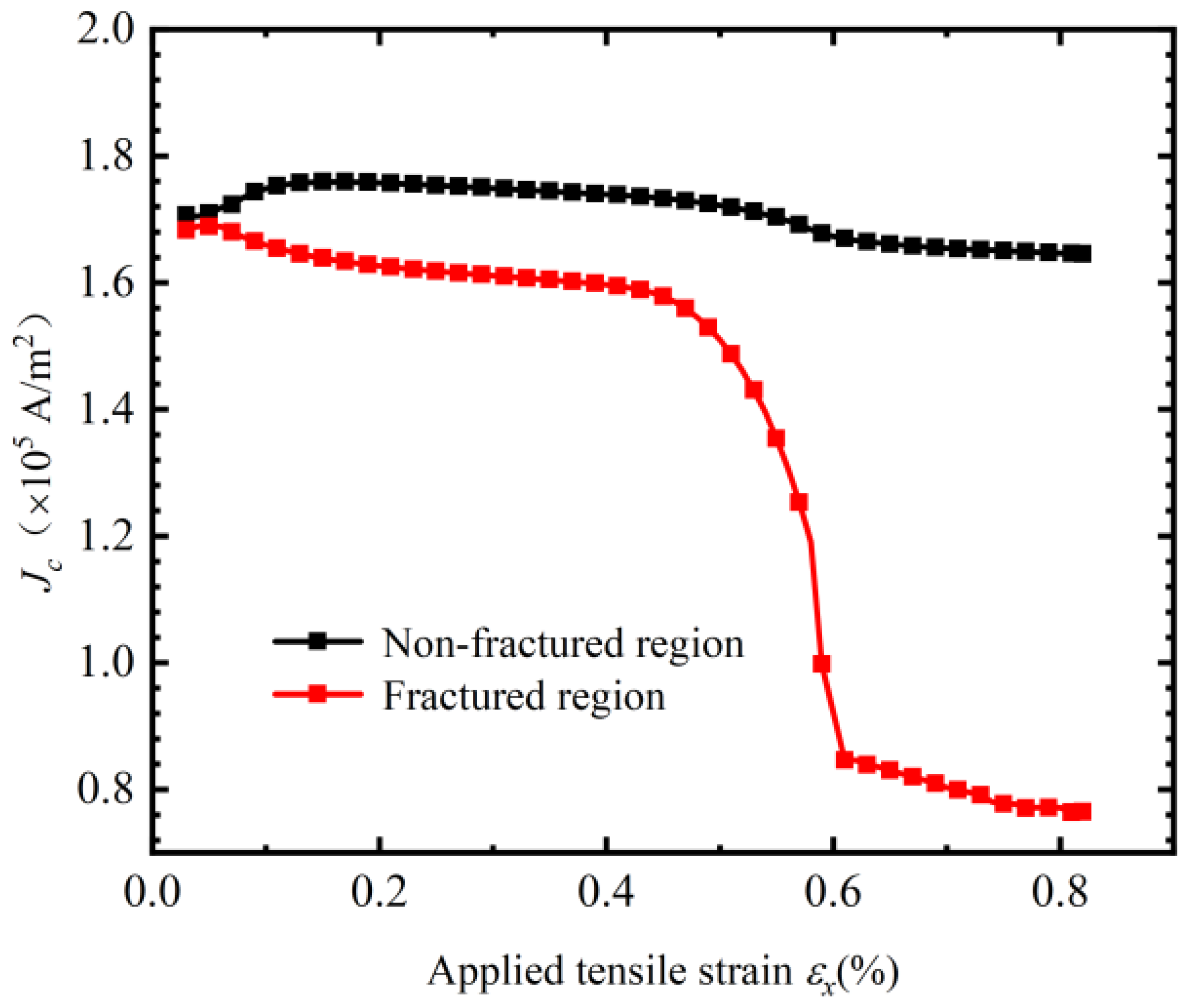
Figure 8 shows the trend of total current density variation of the entire two-dimensional finite element model under different tensile strain conditions. As the strain increases, especially in the range of ε x = 0.4 ~ 0.6 % , the overall current density of the model shows a significant decrease. This trend is consistent with the evolution of current density in the local crack area, further verifying the inhibitory effect of crack propagation on current transmission performance. The decrease in total current density not only reflects the decline in local conductivity of the superconducting layer, but also indicates that the overall current-carrying capacity of the material is gradually deteriorating with crack propagation.
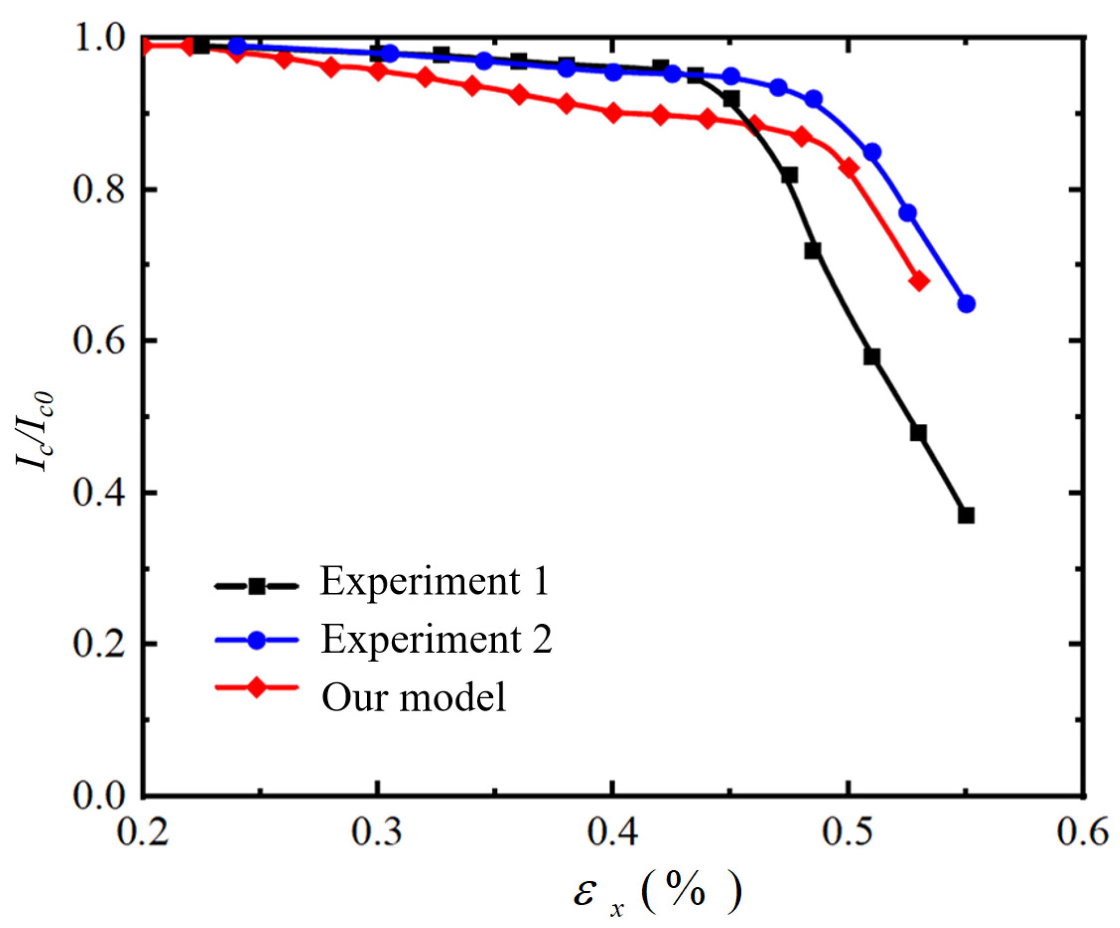
In order to validate the model, we compared the simulation results with experiments and selected the results from reference [47]. In their work, the voltage generation within the voltage–current relationship was determined using a current-sharing model, where the transport current is distributed between the Bi2223 filament and the Ag matrix near the fractured region. This approach accounts for the interaction between superconducting filaments and stabilizing materials under mechanical stress, ensuring accurate representation of electrical behavior at localized damage sites. Figure 9 compares the relationship between critical current attenuation and tensile strain between the experiment and this study. The black square and blue circular curves represent two sets of experimental data [47], while the red diamond curve represents the force electric coupling model. The results indicate that, considering the current diversion effect caused by crack propagation under tensile conditions, the calculated results are within the range of experimental data, verifying the reliability of the established electromechanical coupling model. At lower strain levels, the critical current change in the force electric coupling model is more significant, possibly due to the preset initial crack in the model, which makes it more sensitive to small strain changes, making it easier to induce crack propagation and cause current diversion effects.

4. Conclusions

In conclusion, this paper presents a multi-physic modeling for Bi2212 superconducting round wires, focusing on its electromechanical sensitivity. Combining the fracture phase field model and multi-physics field coupling numerical simulation method, the crack propagation behavior of Bi2212 material under tensile load and its influence on critical current degradation are systematically analyzed. The results indicate that grid size and phase field length scale parameters have a significant impact on crack propagation behavior. By introducing phase field variables into the superconducting constitutive equation, the elastic-electric coupling mechanism has been revealed, and the influence of crack damage on the degradation of critical current is studied. The results indicate that the current is diverted through the silver matrix, resulting in a local decrease in the current density of the superconducting core. When the crack penetrates the whole thickness of the Bi2212 material, the current almost completely bypasses the silver matrix, and the critical current significantly decreases. Especially within the range of tensile strain of ε x = 0.4 ~ 0.6 % , the critical current deteriorates sharply, while the current density in the unbroken region changes little. Additionally, we also obtained the relationship between the current density and the tensile strain, quantitatively explaining the mechanism of critical current degradation of Bi2212. In future studies, the phase field model shall be tested and applied to mesoscopic superconducting systems as specified by work [48,49,50].

Author Contributions

Conceptualization, F.X; formal analysis, K.Z.; investigation, F.X.; writing—original draft preparation, F.X.; writing—review and editing, K.Z.; project administration, F.X.; funding acquisition, F.X. All authors have read and agreed to the published version of the manuscript.

Funding

This research was funded by the National Natural Science Foundation of China grant number 12372149.

Data Availability Statement

The data presented in this study are available on request from the corresponding author.

Conflicts of Interest

The authors declare no conflicts of interest.

References

  1. Shin, J.; Ochiai, S.; Okuda, H.; Mukai, Y.; Matsubayashi, H.; Oh, S.; Ha, D.; Kim, S.; Sato, M. Estimation of Young’s modulus, residual strain and intrinsic fracture strain of Bi2212 filaments in Bi2212/Ag/Ag alloy composite wire. Phys. C Supercond. 2008, 468, 1792–1795. [Google Scholar] [CrossRef]
  2. Katagiri, K.; Shin, H.; Shoji, Y.; Ebisawa, N.; Watanabe, K.; Noto, K.; Okada, T.; Hiraoka, M.; Yuya, S. Tensile strain/transverse compressive stress dependence of critical current in Ag-sheathed Bi (2212) 7-core superconducting wires. Cryogenics 1996, 36, 491–494. [Google Scholar] [CrossRef]
  3. Mao, Z.-H.; Jin, H.; Qin, J.-G.; Liu, F.; Dai, C.; Hao, Q.-B.; Li, C.-S. Axial tensile stress–strain characterization of Bi-2212 round wire with different heat treatments. IEEE Trans. Appl. Supercond. 2017, 27, 1–5. [Google Scholar] [CrossRef]
  4. Godeke, A.; Hartman, M.H.C.; Mentink, M.G.T.; Jiang, J.; Matras, M.; Hellstrom, E.E.; Larbalestier, D.C. Critical current of dense Bi-2212 round wires as a function of axial strain. Supercond. Sci. Technol. 2015, 28, 032001. [Google Scholar] [CrossRef]
  5. Bjoerstad, R.; Scheuerlein, C.; Rikel, M.O.; Ballarino, A.; Bottura, L.; Jiang, J.; Matras, M.; Sugano, M.; Hudspeth, J.; Di Michiel, M. Strain induced irreversible critical current degradation in highly dense Bi-2212 round wire. Supercond. Sci. Technol. 2015, 28, 062002. [Google Scholar] [CrossRef]
  6. Cheggour, N.; Lu, X.F.; Holesinger, T.G.; Stauffer, T.C.; Jiang, J.; Goodrich, L.F. Reversible effect of strain on transport critical current in Bi2Sr2CaCu2O8+x superconducting wires: A modified descriptive strain model. Supercond. Sci. Technol. 2011, 25, 015001. [Google Scholar] [CrossRef]
  7. Li, P.; Naderi, G.; Schwartz, J.; Shen, T. On the role of precursor powder composition in controlling microstructure, flux pinning, and the critical current density of Ag/Bi2Sr2CaCu2Ox conductors. Supercond. Sci. Technol. 2017, 30, 035004. [Google Scholar] [CrossRef]
  8. Shen, T.; Ghosh, A.; Cooley, L.; Jiang, J. Role of internal gases and creep of Ag in controlling the critical current density of Ag-sheathed Bi2Sr2CaCu2Ox wires. J. Appl. Phys. 2013, 113, 213901. [Google Scholar] [CrossRef]
  9. Han, Z.; Skov-Hansen, P.; Freltoft, T. The mechanical deformation of superconducting BiSrCaCuO/Ag composites. Supercond. Sci. Technol. 1997, 10, 371–387. [Google Scholar] [CrossRef]
  10. Wang, Z.; Yong, H.; Zhou, Y. Degradation of critical current in Bi2212 composite wire under compression load. Appl. Math. Mech. 2017, 38, 1773–1784. [Google Scholar] [CrossRef]
  11. Liu, D.; Yong, H.; Zhou, Y. Analysis of critical current density in Bi2Sr2CaCu2O8+x round wire with filament fracture. J. Supercond. Nov. Magn. 2016, 29, 2299–2309. [Google Scholar] [CrossRef]
  12. Yang, Y.; Yong, H.; Zhou, Y. Mechanical behavior in superconducting composite wires. Eur. J. Mech.-A/Solids 2018, 70, 191–202. [Google Scholar] [CrossRef]
  13. Lu, Y.; Wang, Z.; Yong, H.; Zhou, Y. Modeling effects of gas bubbles on the mechanical behaviors of Ag/Bi-2212 round wires using a double cantilever beam bridge model. Cryogenics 2016, 77, 65–73. [Google Scholar] [CrossRef]
  14. Peng, X.; Yong, H.; Zhou, Y. Damage analysis of superconducting composite wire with bridging model. Acta Mech. Solida Sin. 2018, 31, 19–31. [Google Scholar] [CrossRef]
  15. Wang, Y.-F.; Jiang, Z.-F.; Zhang, Z.-X.; Gou, X.-F. Interpretation of compressive strain causing critical current degradation of Bi2212 round wires. IEEE Trans. Appl. Supercond. 2022, 32, 1–8. [Google Scholar] [CrossRef]
  16. Jiang, Z.-F.; Gou, X.-F.; Shen, T.-M. Impact of the complex interface between Bi2Sr2CaCu2Ox filaments and Ag matrix on the quench behavior of composite round wires. IEEE Trans. Appl. Supercond. 2018, 29, 1–9. [Google Scholar] [CrossRef]
  17. Fries, T.-P.; Belytschko, T. The extended/generalized finite element method: An overview of the method and its applications. Int. J. Numer. Methods Eng. 2010, 84, 253–304. [Google Scholar] [CrossRef]
  18. Strouboulis, T.; Copps, K.; Babuška, I. The generalized finite element method. Comput. Methods Appl. Mech. Eng. 2001, 190, 4081–4193. [Google Scholar] [CrossRef]
  19. Chau-Dinh, T.; Zi, G.; Lee, P.-S.; Rabczuk, T.; Song, J.-H. Phantom-node method for shell models with arbitrary cracks. Comput. Struct. 2012, 92–93, 242–256. [Google Scholar] [CrossRef]
  20. Rabczuk, T.; Zi, G.; Gerstenberger, A.; Wall, W.A. A new crack tip element for the phantom—Node method with arbitrary cohesive cracks. Int. J. Numer. Methods Eng. 2008, 75, 577–599. [Google Scholar] [CrossRef]
  21. Khoei, A.R. Extended Finite Element Method: Theory and Applications; John Wiley & Sons: Hoboken, NJ, USA, 2015. [Google Scholar]
  22. Zhao, W.; Du, C.; Jiang, S. An adaptive multiscale approach for identifying multiple flaws based on XFEM and a discrete artificial fish swarm algorithm. Comput. Methods Appl. Mech. Eng. 2018, 339, 341–357. [Google Scholar] [CrossRef]
  23. Alessi, R.; Marigo, J.-J.; Vidoli, S. Gradient damage models coupled with plasticity: Variational formulation and main properties. Mech. Mater. 2015, 80, 351–367. [Google Scholar] [CrossRef]
  24. Askes, H.; Pamin, J.; De Borst, R. Dispersion analysis and element-free Galerkin solutions of second-and fourth-order gradient-enhanced damage models. Int. J. Numer. Methods Eng. 2000, 49, 811–832. [Google Scholar] [CrossRef]
  25. Verhoosel, C.V.; Scott, M.A.; Hughes, T.J.R.; de Borst, R. An isogeometric analysis approach to gradient damage models. Int. J. Numer. Methods Eng. 2011, 86, 115–134. [Google Scholar] [CrossRef]
  26. Bui, T.Q.; Hu, X. A review of phase-field models, fundamentals and their applications to composite laminates. Eng. Fract. Mech. 2021, 248, 107705. [Google Scholar] [CrossRef]
  27. Diehl, P.; Lipton, R.; Wick, T.; Tyagi, M. A comparative review of peridynamics and phase-field models for engineering fracture mechanics. Comput. Mech. 2022, 69, 1259–1293. [Google Scholar] [CrossRef]
  28. Miehe, C.; Welschinger, F.; Hofacker, M. Thermodynamically consistent phase-field models of fracture: Variational principles and multi-field FE implementations. Int. J. Numer. Methods Eng. 2010, 83, 1273–1311. [Google Scholar] [CrossRef]
  29. Diehl, P.; Prudhomme, S.; Lévesque, M. A review of benchmark experiments for the validation of peridynamics models. J. Peridynamics Nonlocal Model. 2019, 1, 14–35. [Google Scholar] [CrossRef]
  30. Borden, M.J.; Verhoosel, C.V.; Scott, M.A.; Hughes, T.J.; Landis, C.M. A phase-field description of dynamic brittle fracture. Comput. Methods Appl. Mech. Eng. 2012, 217–220, 77–95. [Google Scholar] [CrossRef]
  31. Bourdin, B.; Francfort, G.; Marigo, J.-J. Numerical experiments in revisited brittle fracture. J. Mech. Phys. Solids 2000, 48, 797–826. [Google Scholar] [CrossRef]
  32. Hai, L.; Li, J. A rate-dependent phase-field framework for the dynamic failure of quasi-brittle materials. Eng. Fract. Mech. 2021, 252, 107847. [Google Scholar] [CrossRef]
  33. Han, J.; Matsubara, S.; Moriguchi, S.; Terada, K. Variational crack phase-field model for ductile fracture with elastic and plastic damage variables. Comput. Methods Appl. Mech. Eng. 2022, 400, 115577. [Google Scholar] [CrossRef]
  34. Teichtmeister, S.; Kienle, D.; Aldakheel, F.; Keip, M.-A. Phase field modeling of fracture in anisotropic brittle solids. Int. J. Non-linear Mech. 2017, 97, 1–21. [Google Scholar] [CrossRef]
  35. Wu, J.-Y. A unified phase-field theory for the mechanics of damage and quasi-brittle failure. J. Mech. Phys. Solids 2017, 103, 72–99. [Google Scholar] [CrossRef]
  36. Wu, J.-Y. A geometrically regularized gradient-damage model with energetic equivalence. Comput. Methods Appl. Mech. Eng. 2018, 328, 612–637. [Google Scholar] [CrossRef]
  37. Wu, J.-Y.; Nguyen, V.P. A length scale insensitive phase-field damage model for brittle fracture. J. Mech. Phys. Solids 2018, 119, 20–42. [Google Scholar] [CrossRef]
  38. Chen, W.-X.; Wu, J.-Y. Phase-field cohesive zone modeling of multi-physical fracture in solids and the open-source implementation in Comsol Multiphysics. Theor. Appl. Fract. Mech. 2022, 117, 103153. [Google Scholar] [CrossRef]
  39. Miehe, C.; Aldakheel, F.; Raina, A. Phase field modeling of ductile fracture at finite strains: A variational gradient-extended plasticity-damage theory. Int. J. Plast. 2016, 84, 1–32. [Google Scholar] [CrossRef]
  40. Ulmer, H.; Hofacker, M.; Miehe, C. Phase field modeling of brittle and ductile fracture. PAMM 2013, 13, 533–536. [Google Scholar] [CrossRef]
  41. Li, B.; Peco, C.; Millán, D.; Arias, I.; Arroyo, M. Phase-field modeling and simulation of fracture in brittle materials with strongly anisotropic surface energy. Int. J. Numer. Methods Eng. 2015, 102, 711–727. [Google Scholar] [CrossRef]
  42. Kuhn, C.; Müller, R. Phase field simulation of thermomechanical fracture. Proc. Appl. Math. Mech. 2009, 9, 191–192. [Google Scholar] [CrossRef]
  43. Francfort, G.; Marigo, J.-J. Revisiting brittle fracture as an energy minimization problem. J. Mech. Phys. Solids 1998, 46, 1319–1342. [Google Scholar] [CrossRef]
  44. Ahoranta, M.; Lehtonen, J.; Tarhasaari, T. Finite element models for thermal stress, axial tension, bending, and transversalcompression of filamentary Bi-2223 tapes. Supercond. Sci. Technol. 2008, 22, 015012. [Google Scholar] [CrossRef]
  45. Sugano, M.; Osamura, K.; Nyilas, A. Estimation of the coefficient of thermal expansion of Bi2223 at low temperature. Supercond. Sci. Technol. 2003, 16, 1064–1070. [Google Scholar] [CrossRef]
  46. Yusheng, H.; Jiong, X.; Sheng, J.; Aisheng, H.; Jincang, Z. Ultrasonic investigations of the layered perovskite ceramic superconducting systems. Phys. B Condens. Matter 1990, 165–166, 1283–1284. [Google Scholar] [CrossRef]
  47. Shin, J.K.; Ochiai, S.; Okuda, H.; Sugano, M.; Oh, S.S. Change of the V–I curve and critical current with applied tensile strain due to cracking of filaments in Bi2223composite tape. Supercond. Sci. Technol. 2008, 21, 115007. [Google Scholar] [CrossRef]
  48. Gelhausen, J.; Eschrig, M. Theory of a weak-link superconductor-ferromagnet Josephson structure. Phys. Rev. B 2016, 94, 104502. [Google Scholar] [CrossRef]
  49. Maeda, A.; Espinoza, L.B.G. Josephson Junction and Josephson Device. U.S. Patent 8200304 B2, 12 June 2012. [Google Scholar]
  50. Pomorski, K.; Prokopow, P. Possible existence of field-induced Josephson junctions. Phys. Status Solidi B 2012, 249, 1805–1813. [Google Scholar] [CrossRef]
Figure 1. Two-dimensional finite element model of the longitudinal profile of Bi2212 superconducting round wires.
Modelling 06 00119 g001
Figure 2. Display of local mesh around the crack (a), and (be) are local two-dimensional finite element models with mesh sizes h max = 2 l 0 ,   2 l 0 / 3 ,   l 0 / 2 ,   l 0 / 3 .
Modelling 06 00119 g002
Figure 3. Nominal stress-displacement curves for different mesh sizes.
Modelling 06 00119 g003
Figure 4. The phase field variable for different length scales. (I) l 0 = 0.001 mm, (a) ε x = 0.46%, (b) ε x = 0.5%, (c) ε x = 0.54%, (II) l 0 = 0.002 mm, (d) ε x = 0.46%, (e) ε x = 0.5%, (f) ε x = 0.54%, (III) l 0 = 0.003 mm, (g) ε x = 0.46%, (h) ε x = 0.5%, (i) ε x = 0.54%.
Modelling 06 00119 g004
Figure 5. Nominal stress-displacement curves for different length scales.
Modelling 06 00119 g005
Figure 6. Two-dimensional Bi2212 finite element model (including current flow direction in red colour).
Modelling 06 00119 g006
Figure 7. Current density distribution for tensile strain (red arrows indicate the direction of the current) (a) ε x = 0.3%, (b) ε x = 0.5%, (c) ε x = 0.6%.
Modelling 06 00119 g007
Figure 8. Curves of total current density versus nominal strain in fractured and unfractured regions.
Modelling 06 00119 g008
Figure 9. Comparison of experimental [47] and numerical studies on current degradation with nominal strain.
Modelling 06 00119 g009
Table 1. Geometric parameters of the two-dimensional Bi2212 longitudinal section finite element model.
Thickness of the model for the Bi2212 round wire 2.14   ×   10 3   μ m
Thickness of superconducting core wire 1.2   ×   10 2 μm
Thickness of Ag monolayer 1   ×   10 2   μ m
Thickness of AgMg protective layer 4.8   ×   10 2   μ m
Table 2. Material parameters of the two-dimensional Bi2212.
E (GPa) ν
Bi221238.80.2
Ag920.37
AgMg104.230.37
Table 3. Physical parameters of the two-dimensional Bi2212 longitudinal section finite element model.
Critical energy release rate G c 80 ~ 120   J / m 2
Length scale parameter l 0 0.001 ~ 0.002 mm
Mesh size h max   0.0003 ~ 0.001 mm
Table 4. Material parameters of the two-dimensional Bi2212 longitudinal section finite element model.
ζ (S/m) ϵ r E (GPa) ν
Bi2212 1   ×   10 9 2538.80.2
Ag 6.3   ×   10 7 1920.37
AgMg 3.7   ×   10 6 1104.230.37
Table 5. Electrical parameters involved in the equations [46].
ε x 0~1%
J c 0 1   ×   10 12   A / m 2
E c 1   ×   10 5   V / m
ζ s c 1   ×   10 14   S / m
ζ 2212 1   ×   10 3   S / m
n 20
Table 6. Electric boundary conditions.
Right end of the model V = 0
Left end of the model σ s c V · n = J
Upper and lower boundaries V · n = 0
Bi2212/Ag interface ρ s = 1   ×   10 12   Ω m 2
Disclaimer/Publisher’s Note: The statements, opinions and data contained in all publications are solely those of the individual author(s) and contributor(s) and not of MDPI and/or the editor(s). MDPI and/or the editor(s) disclaim responsibility for any injury to people or property resulting from any ideas, methods, instructions or products referred to in the content.