Communication

Switched Modeling and Sampled Switching Control for DC-DC Boost Converters with Uncertainty

School of IoT Engineering, Jiangnan University, Wuxi 214122, China
*
Authors to whom correspondence should be addressed.
Modelling 2025, 6(3), 86; https://doi.org/10.3390/modelling6030086
Submission received: 26 June 2025 / Revised: 2 August 2025 / Accepted: 18 August 2025 / Published: 20 August 2025

Abstract

In this paper, a switched model for DC-DC boost converters with modeling uncertainty is considered. Based on the switched model, a continuous switching control law is first designed to guarantee the robust stability of the closed-loop system. Then, to reduce the data transmission amount and ease the communication burden, a sampled-data switching control law is explored, where the switching action is executed based on a state-dependent condition at each sampling time. The proposed control strategies can track a specific reference point and varying reference points in the presence of modeling uncertainty. Finally, the simulation results show that the proposed sampling switch control reduces steady-state errors and the transient response is significantly smoother. These results confirm the effectiveness and practical potential of the proposed approach.

Graphical Abstract

1. Introduction

DC-DC converters have a wide range of applications in industry and life. Established methodologies for regulating DC-DC converters encompass both linear and switching control frameworks. The former, pioneered by Middlebrook [1], utilizes small-signal averaging models [1,2], while the latter employs pulse width modulation (PWM) techniques [3,4]. Subsequent work [2] extended these approaches through state observers that derive model parameters from equivalent linear circuits. The averaging linear system has many drawbacks when considering the control of the output voltage as it sacrifices parts of the dynamic performance. Furthermore, it has difficulty in tracking varying reference signals. PWM-based control methods make it possible to adjust the output voltage without changing the topology of the circuit, and many studies have combined PWM with other advanced control methods. Hardware-oriented innovations like the Switched-Capacitor Delay Deadtime Controller (SCD-DTC) in [3] demonstrate how deadtime optimization and reverse inductor current elimination can significantly improve power efficiency for DC-DC converters, though this remains a circuit implementation enhancement rather than a control strategy innovation. Building upon this foundation, sampled-data output feedback control for PWM-based DC-DC buck converters was examined in [5]. To circumvent the requirement for current sensing, ref. [6] developed an observer-based finite-time output feedback controller. This approach ensures convergence of the system states to their equilibrium within a defined time interval. An observer-based approach for DC-DC buck converters was presented in [7], which combines the sliding mode control and PWM. In [4], a sampled-data output voltage regulation algorithm was proposed. The algorithm can overcome actuator and sensor failures. However, these methods focus on the control design of the duty ratio instead of the design of the switching rule, which is more distinct and concise.
In fact, DC-DC converter system can be modeled as a switched system, which is a specific type of hybrid systems. Based on the hybrid model of DC-DC converters, a more precise and concise control property can be achieved. Many important problems concerning the switched control have been extensively studied by far. The stability of this kind of switched systems has been analyzed through different types of Lyapunov functions, such as the common Lyapunov function [8,9,10], the multiple Lyapunov function [11,12,13,14], the piecewise quadratic Lyapunov function [15,16,17,18], and so on. There are also some researches concerning the switched control for DC-DC converters. Different from the traditional control methods, the switching control of DC-DC converters focused on the design of the switching rule. Deaecto [19] established a switching function guaranteeing global stability and identified switchable equilibrium points. Independently, Yan [20] developed predictive switching control for DC-DC buck converters to mitigate switching signal latency. When considering the practical application of switching control, sampled-data implementation is unavoidable since the switching control is always applied through a digital platform. Yan [21] developed sampled-data control for switched DC-DC converters; subsequent experimental validation via laboratory prototype confirmed the algorithm’s superior performance. Another problem when applying the control algorithm is that parameter uncertainty and external disturbance always exists. Advanced intelligent control methodologies now enable optimized precision in DC converter regulation under uncertain operating conditions. For instance, ref. [22] enhanced Four-Switch Buck–Boost (FSBB) converter performance by optimizing a PID controller using a hybrid chaotic particle swarm optimized backpropagation neural network (CPSO-BPNN). This approach aimed to improve dynamic response and robustness. Nevertheless, sophisticated control approaches may still exhibit deficiencies including sluggish convergence and stability constraints. Addressing these limitations, Yang [23] recently investigated robust H characteristics in parametric-uncertain boost converter switched control systems, deriving a sufficient condition for switching rule existence. Additionally, the authors in [24] presented a robust switching control design for a DC-DC boost converter under uncertain equilibrium conditions caused by input and load perturbations. This work introduced a parameter estimator for real-time equilibrium point updates, along with techniques to mitigate associated noise amplification issues, and validated the approach through simulation and experiment. Although there are some preliminary results, the practical implementation of switching control for DC-DC converters with modeling uncertainty has not been fully investigated. Moreover, unstable switching behaviors in power converters can lead to critical safety hazards such as voltage overshoot, thermal runaway, and device damage. These risks are particularly pronounced under modeling uncertainties or sampling-induced delays [25]. Recent studies (e.g., [25]) address such challenges by analyzing convergence regions in sampled-data switched affine systems, highlighting the need for robust invariance guarantees in practical designs.
In this paper, the DC-DC boost converter system with modeling uncertainty is considered. The system is modeled as a switching system with two subsystems. Continuous and sampled-data switching control laws are introduced, and corresponding sufficient existence conditions are derived through linear matrix inequalities (LMIs). Piecewise quadratic Lyapunov functions are applied in order to reduce the conservation of the results. This approach mitigates the convergence conservatism observed in non-uniform sampling methods like [25]. Both of the control strategies are designed off-line and are able to track varying reference signals without changing the elements of the circuits in the presence of modeling uncertainty. The sampled-data switching control law can be directly applied on the practical implementation.
This paper is structured as follows: Section 2 presents a switched DC-DC boost converter model with parametric uncertainties and foundational lemmas. Subsequent sections develop switching strategies: continuous and sampled-data approaches in Section 3, followed by numerical validation of method efficacy in Section 4. Concluding remarks appear in Section 5.
Notation: R n × m represents the space of all n × m real matrices. · denotes the vector norm or the matrix norm. λ min ( A ) represents the minimal eigenvalue of matrix A. The convex combination of A 1 , A 2 and B 1 , B 2 are denoted as A ( λ ) and B ( λ ) , which satisfy A ( λ ) = λ A 1 + ( 1 λ ) A 2 and B ( λ ) = λ B 1 + ( 1 λ ) B 2 where λ [ 0 , 1 ] . The symbol * denotes a block that can be inferred by symmetry. I represents identity matrices with proper dimensions. For a square symmetric matrix, P > 0 ( P < 0 , respectively) means that P is positive definite (negative definite, respectively). co { A } denotes the convex hull of the set A .

2. Problem Statement

A switched DC-DC boost converter model accommodating parametric uncertainties is introduced herein. Figure 1 depicts the circuit topology, where key components include the following: DC power supply E, inductive element L with parasitic resistance R 0 , capacitive element C, load resistance R, diode D, and switching device S. The modeling uncertainty Δ R and state variables—inductor current i L and capacitor voltage u C —complete the system representation.
Circuit-derived dynamics during switching intervals follow these state-space representations [19]:
i ˙ L u ˙ C = R 0 L 0 0 1 ( R + Δ R ) C i L u C + E L 0 , t t on
i ˙ L u ˙ C = R 0 L 1 L 1 C 1 ( R + Δ R ) C i L u C + E L 0 , t t off
where t on and t off denote switch-open and switch-closed intervals, respectively. Let x ( t ) = i L u C . It is assumed that the threshold of uncertain parameters in the resistance Δ R is sufficiently small. Then applying Taylor expansion to separate the modeling uncertainty, we obtain the switched model of DC-DC boost converters with modeling uncertainty as follows:
x ˙ ( t ) = ( A σ + Δ A σ ) x ( t ) + B σ , σ K = 1 , 2 ,
where A 1 = R 0 L 0 0 1 R C , A 2 = R 0 L 1 L 1 C 1 R C , Δ A 1 = Δ A 2 = 0 0 0 1 R 2 C Δ R , B 1 = B 2 = E L 0 .
Assume that Δ R [ Δ R max Δ R max ] , then the uncertain part can be written as
Δ A σ ( t ) = M σ F σ ( t ) N σ , σ K ,
where
M 1 = M 2 = 1 0 0 1 , N 1 = N 2 = 0 0 0 Δ R max R 2 C , F σ ( t ) F σ ( t ) I .
The averaged model of DC-DC boost converters can be written as follows:
x ˙ ( t ) = A ( λ ) x ( t ) + B ( λ ) ,
where A ( λ ) and B ( λ ) are the convex combination of A 1 , A 2 and B 1 , B 2 , respectively.
According to [19], the attainable equilibrium can be obtained as
x r = i r u r = A ( λ ) B ( λ ) .
The control problem can be summarized as follows. Based on the continuous-time plant with modeling uncertainty, design a continuous switching strategy σ ( x ( t ) ) and a sampled switching strategy σ ( x ( t k ) ) so that the state of the system x x r as t , where t k = k T , k N stands for the sampling time, and T represents the sampling period.
The following lemmas are useful in the main results.
Lemma 1.
Given any symmetric constant matrix Q R n × n (where Q = Q ), scalars 0 t 1 < t 2 , and a continuously differentiable vector function x : [ t 1 , t 2 ] R n ensuring all relevant integrals exist, the following holds:
( t 2 t 1 ) t 1 t 2 e α s x ˙ ( s ) Q x ˙ ( s ) d s ( x ( t 2 ) x ( t 1 ) ) Q ( x ( t 2 ) x ( t 1 ) ) .
Proof. 
Using Schur’s complement, it is easy to see
e α s x ˙ ( s ) Q x ˙ ( s ) x ˙ ( s ) x ˙ ( s ) Q 1 0 ,
for any 0 t 1 s t 2 . Integrating of the above inequality from t 1 to t 2 yields
t 1 t 2 e α s x ˙ ( s ) Q x ˙ ( s ) d s x ( t 2 ) x ( t 1 ) x ( t 2 ) x ( t 1 ) ( t 2 t 1 ) Q 1 0 .
Using Schur’s complement again, one can derive (6). This completes the proof. □
Lemma 2 ([26]).
Consider real matrices X, Y, and a matrix-valued function F ( t ) , all of compatible dimensions. For any scalar ε > 0 where F ( t ) F ( t ) I , the following inequality holds:
X F ( t ) Y + Y F ( t ) X ε 1 X X + ε Y Y .
Lemma 3 ([27]).
Consider real matrices A, M, N, and F of compatible dimensions with F F I . For any positive definite matrix Q > 0 and scalar φ satisfying Q φ M M > 0 , the following inequality holds:
( A + M F N ) Q ( A + M F N ) A Q A + φ 1 N N + A Q M ( φ I M Q M ) 1 M Q A .

3. Main Results

This section provides the main results of this paper related to the switching rule design and the stability of closed-loop systems. Both continuous and sampled switching strategies are considered. Sufficient conditions to ensure the stability of closed-loop systems under the proposed methods will be established.

3.1. Continuous Switching Strategy Design

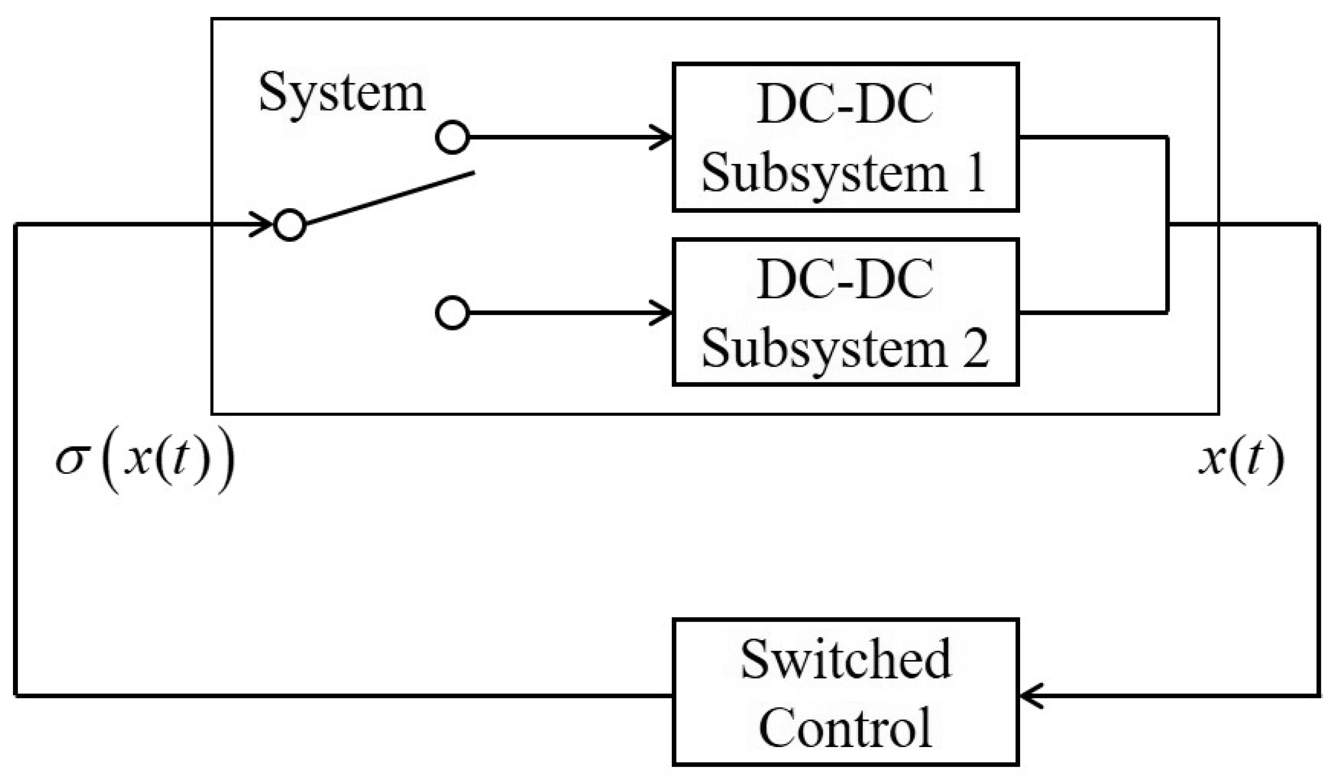
The principle of continuous switched controller design is shown in Figure 2.
Theorem 1.
Given a piecewise quadratic Lyapunov functional candidate V ( t ) defined as
V ( t ) = min j K e ( t ) P j e ( t ) ,
where e ( t ) = x ( t ) x r , if the condition
V ˙ ( t ) + α V ( t ) < κ x r x r ,
is satisfied, then the state x ( t ) of the DC-DC boost converter will converge to a finite region B 1 given by
B 1 = x ( t ) R 2 : min j K λ min ( P j ) x x r 2 < κ x r x r α .
Proof. 
By using the comparison principle, it follows from (8) that
V ( t ) < e α t V ( 0 ) + κ x r x r 0 t e α s d s = e α t V ( 0 ) + κ x r x r α ( e α t 1 ) = e α t V ( 0 ) κ x r x r α + κ x r x r α ,
which means that the state of system x ( t ) will converge to the region defined by (9) as t . □
Remark 1.
The concept of piecewise quadratic Lyapunov functions plays a central role in establishing the stability of switched systems under consideration. Intuitively, these functions can be viewed as energy-like measures that decrease as the system evolves over time. Unlike a single global Lyapunov function, the piecewise structure allows for a tailored stability analysis across different regions of the state space, which is particularly useful for switched or hybrid systems. The sets B 1 and B 2 represent regions where the Lyapunov function guarantees convergence, effectively acting as “safe zones” within which the system state is eventually trapped. One can visualize these sets as level sets (i.e., ellipsoidal or sublevel regions) corresponding to bounded energy levels where the system settles. This interpretation helps bridge the theoretical derivation with the system’s expected behavior, offering a more intuitive grasp of the stability guarantees.
The following theorem shows a sufficient condition to ensure the stability of the closed-loop system.
Theorem 2.
Examine the switched DC-DC boost converter in (3). For prescribed positive scalars α, ε, κ, suppose there is a λ Λ and symmetric positive-definite matrices P j R 2 × 2 , j K satisfying both
P j A i + A i P j + ε 2 N i N i + α P j + P j P r * * ε 2 N i N i P j M i ε 2 N i N i κ I 0 * ε 2 I < 0 ,
A ( λ ) x r + B ( λ ) = 0 ,
for all i K . Then the switching law
σ ( x ( t ) ) = arg min i K ( x ( t ) x r ) P j ( A i x r + B i ) , j K
ensures state x ( t ) convergence to the domain B 1 for all x ( t ) .
Proof. 
Assume without loss of generality that the Lyapunov functional
V ( t ) = min j K e ( t ) P j e ( t ) = e ( t ) P j e ( t ) .
This formulation requires
e ( t ) ( P j P r ) e ( t ) < 0 , r K .
Differentiating the Lyapunov candidate (7) along system trajectories (3) yields
V ˙ ( t ) = 2 e ( t ) P j A σ + Δ A σ x ( t ) + B σ = 2 e ( t ) P j A σ e ( t ) + 2 e ( t ) P j Δ A σ x ( t ) + 2 e ( t ) P j ( A σ x r + B σ ) = e ( t ) ( P j A σ + A σ P j ) e ( t ) + 2 e ( t ) P j M σ F σ ( t ) N σ x ( t ) + min i K 2 e ( t ) P j ( A i x r + B i ) = e ( t ) ( P j A σ + A σ P j ) e ( t ) + 2 e ( t ) P j M σ F σ ( t ) N σ x ( t ) + min λ Λ 2 e ( t ) P j ( A ( λ ) x r + B ( λ ) ) = e ( t ) ( P j A σ + A σ P j ) e ( t ) + 2 e ( t ) P j M σ F σ ( t ) N σ x ( t ) e ( t ) ( P j A σ + A σ P j ) e ( t ) + e ( t ) ε 2 P j M σ M σ P j e ( t ) + x ( t ) ε 2 N σ N σ x ( t ) = e ( t ) ( P j A σ + A σ P j + ε 2 P j M σ M σ P j + ε 2 N σ N σ ) e ( t ) + x r ε 2 N σ N σ x r + 2 e ( t ) ε 2 N σ N σ x r .
Verification of the condition (8) necessitates
ξ ( t ) Φ 1 ε 2 N σ N σ * ε 2 N σ N σ κ I ξ ( t ) < 0 ,
where Φ 1 = P j A σ + A σ P j + ε 2 P j M σ M σ P j + ε 2 N σ N σ + α P j , ξ ( t ) = e ( t ) x r . Using Schur’s complement and combining (13), we can derive LMI (10). This concludes the proof of Theorem 2. □
The steps in the proposed continuous switching strategy are as follows:
Step 1.
Offline Design:
(a)
Solve LMIs (10) and equilibrium condition (11) from Theorem 2.
(b)
Store the solutions P 1 , P 2 , and x r .
Step 2.
Online Execution (at each time t):
(a)
Measure state x ( t ) and compute error e ( t ) = x ( t ) x r .
(b)
Determine active Lyapunov matrix
j * = arg min j e ( t ) P j e ( t ) .
(c)
Compute switching signal
σ ( t ) = arg min i K ( x ( t ) x r ) P j * ( A i x r + B i ) .
(d)
Apply the switching signal σ ( t ) to the converter (1)(2).
Step 3.
Repeat Step 2 continuously.

3.2. Sampled Switching Strategy Design

It is worth mentioning that the continuous control law proposed above is difficult to implement in practical application. To overcome this problem, in this section, a sampled switching control law is presented.
As is shown in Figure 3, the sampled switched control system considered in this section consists of the following modules: the boost converter system, the sampler, the switched controller, and the zero-order holder (ZOH).
Theorem 3.
Define a piecewise quadratic Lyapunov functional candidate V ( t ) as
V ( t ) = min j K e ( t ) P j e ( t ) ,
where e ( t ) = x ( t ) x r . For any positive scalars α, ρ, and κ, satisfaction of the inequality
V ˙ ( t ) + α V ( t ) + U ˙ ( t ) + α U ( t ) < ρ T + κ x r x r ,
guarantees exponential convergence of the system state x ( t ) to the compact region B 2 :
B 2 = x ( t ) R 2 : min j K λ min ( P j ) x x r 2 < ρ T + κ x r x r α .
Here, T denotes the sampling period, and U ( t ) is a continuous function that is differentiable over [ t k , t k + 1 ) with U ( t k ) = 0 and U ( t ) > 0 for t ( t k , t k + 1 ) .
Proof. 
At time t k , U ( t k ) = 0 . Hence, for t [ t k , t k + 1 ) , if (15) holds, applying comparison principle, we have
V ( t ) < e α ( t t k ) ( V ( t k ) + U ( t k ) ) + θ e α t t k t e α s d s U ( t ) < e α ( t t k ) V ( t k ) θ α + θ α ,
where θ = ρ T + κ x r x r . This inequality implies V ( t k + 1 ) < V ( t k + 1 ) + U ( t k + 1 ) < V ( t k ) . Iterative application reveals the bound
V ( t ) < e α ( t t k ) V ( t k ) θ α + θ α < e α ( t t k ) e α ( t k t k 1 ) V ( t k 1 ) θ α + θ α θ α + θ α < e α ( t t k 1 ) V ( t k 1 ) θ α + θ α < · · · < e α t V ( 0 ) θ α + θ α ,
Thus, V ( t ) converges exponentially to θ α as t , establishing exponential state convergence to B 2 as defined in (16). □
Remark 2.
Owing to the definition of V ( t ) in (14) and the boundary condition U ( t k ) = 0 , the composite function V ( t ) + U ( t ) remains non-increasing at sampling instants. The function U ( t ) is added to ensure that the whole Lyapunov function V ( t ) + U ( t ) can quickly decrease during the sampling interval [ t k , t k + 1 ) .
Remark 3.
In Theorem 3, a typical U ( t ) can be chosen as
U ( t ) = ( t k + 1 t ) e α t t k t e α s e ˙ ( s ) Q σ e ˙ ( s ) d s .
In this case, the function V ( t ) + U ( t ) becomes a piecewise quadratic Lyapunov-Krasovskii function. Based on the particular function U ( t ) , the following theorem gives a stabilization result for the switched DC-DC boost converter system.
Theorem 4.
Examine the switched DC-DC boost converter in (3). For prescribed positive scalars α, ρ, κ, ε 1 , ε 2 , and φ, suppose there is a λ Λ and symmetric positive-definite matrices P j R 2 × 2 , j K satisfying the LMIs:
Φ 11 Φ 12 T A i Q i B i P j M i * Φ 22 T A i Q i B i 0 * * T B i Q i B i ρ T 0 * * * ε 1 2 I * * * * * * * * A i Q i M i 0 A i Q i M i 0 0 B i Q i M i 0 0 M i Q i M i φ 2 I 0 * T ε 2 2 I < 0
Φ 11 Φ 12 T ( P j P r ) * Φ 22 T A i P j * * T e α T Q i + T 2 ( P j P r ) * * * * * * * * * 0 P j M i A i Q i M i 0 0 A i Q i M i 0 0 0 ρ T 0 0 * ε 1 2 I 0 * * M i Q i M i φ 2 I < 0
and the equilibrium condition
A ( λ ) x r + B ( λ ) = 0 ,
for all i K , where
Φ 11 = P j A i + A i P j + α P j + A i Q i A i + ( ε 1 2 + φ 2 + ε 2 2 ) N i N i + P j P r , Φ 12 = A i Q i A i + ( ε 1 2 + φ 2 + ε 2 2 ) N i N i , Φ 22 = A i Q i A i + ( ε 1 2 + φ 2 + ε 2 2 ) N i N i κ I .
Under these conditions, the sampled switching law
σ ( x ( t k ) ) = arg min i K ( x ( t k ) x r ) P j ( A i x r + B i ) , j K
ensures state x ( t ) convergence to the region B 2 .
Proof. 
For the simplicity of the proof, define τ = t t k and ν ( t ) = e ( t ) e ( t k ) τ . Without loss of generality, we assume
V ( t k ) = min j K e ( t k ) P j e ( t k ) = e ( t k ) P j e ( t k ) .
The assumption above is satisfied only if
e ( t k ) ( P j P r ) e ( t k ) < 0 , r K ,
which is equivalent to
η ( t ) Υ r ( τ ) η ( t ) < 0 ,
where η ( t ) = e ( t ) x r ν ( t ) 1 ,
Υ r ( τ ) = P j P r 0 τ ( P j P r ) 0 * 0 0 0 * * τ 2 ( P j P r ) 0 * * * 0 .
The derivation of (14) along with the trajectory of (3) gives
V ˙ ( t ) = 2 e ( t ) P j A σ e ( t ) + 2 e ( t ) P j Δ A σ x ( t ) + 2 e ( t ) P j ( A σ x r + B σ ) = 2 e ( t ) P j A σ e ( t ) + 2 e ( t ) P j M σ F σ ( t ) N σ x ( t ) + 2 e ( t ) P j ( A σ x r + B σ ) = 2 e ( t ) P j A σ e ( t ) + 2 e ( t ) P j M σ F σ ( t ) N σ x ( t ) + 2 τ ν ( t ) P j ( A σ x r + B σ ) + min i K 2 e ( t k ) P j ( A i x r + B i ) = 2 e ( t ) P j A σ e ( t ) + 2 e ( t ) P j M σ F σ ( t ) N σ x ( t ) + 2 τ ν ( t ) P j ( A σ x r + B σ ) + min λ Λ 2 e ( t k ) P j ( A ( λ ) x r + B ( λ ) ) = 2 e ( t ) P j A σ e ( t ) + 2 e ( t ) P j M σ F σ ( t ) N σ x ( t ) + 2 τ ν ( t ) P j ( A σ x r + B σ ) e ( t ) ( P j A σ + A σ P j + ε 1 2 P j M σ M σ P j + ε 1 2 N σ N σ ) e ( t ) + x r ε 1 2 N σ N σ x r + 2 e ( t ) ε 1 2 N σ N σ x r + 2 τ ν ( t ) P j A σ x r + 2 τ ν ( t ) P j B σ .
Then, we have
V ˙ ( t ) + α V ( t ) η ( t ) Ω 1 ( τ ) η ( t ) ,
where
Ω 1 ( τ ) = Π 1 ε 1 2 N i N i 0 0 * ε 1 2 N i N i τ A i P j 0 * * 0 τ P j B i * * * 0 , Π 1 = P j A i + A i P j + ε 1 2 N i N i + α P j + ε 1 2 P j M i M i P j .
On the other hand, the derivation of (18) along with the trajectory of (3) satisfies
U ˙ ( t ) + α U ( t ) = e α t t k t e α s e ˙ ( s ) Q σ e ˙ ( s ) d s + ( t k + 1 t ) e ˙ ( t ) Q σ e ˙ ( t ) e α ( t k t ) ( t k + 1 t ) e ˙ ( t k ) Q σ e ˙ ( t k ) e α t t k t e α s e ˙ ( s ) Q σ e ˙ ( s ) d s + ( t k + 1 t ) e ˙ ( t ) Q σ e ˙ ( t ) .
By Lemma 1, the inequality above yields
U ˙ ( t ) + α U ( t ) τ e α τ ν ( t ) Q σ ν ( t ) + ( t k + 1 t ) e ˙ ( t ) Q σ e ˙ ( t ) = τ e α τ ν ( t ) Q σ ν ( t ) + ( t k + 1 t ) B σ Q σ B σ + 2 ( t k + 1 t ) B σ Q σ ( A σ + Δ A σ ) x ( t ) + ( t k + 1 t ) x ( t ) ( A σ + Δ A σ ) Q σ ( A σ + Δ A σ ) x ( t ) = τ e α τ ν ( t ) Q σ ν ( t ) + ( t k + 1 t ) B σ Q σ B σ + 2 ( t k + 1 t ) B σ Q σ A σ x ( t ) + 2 ( t k + 1 t ) B σ Q σ M σ F σ ( t ) N σ x ( t ) + ( t k + 1 t ) x ( t ) ( A σ + M σ F σ ( t ) N σ ) Q σ ( A σ + M σ F σ ( t ) N σ ) x ( t ) .
By applying Lemmas 2 and 3, one can further obtain
U ˙ ( t ) + α U ( t ) τ e α τ ν ( t ) Q σ ν ( t ) + ( T τ ) B σ Q σ B σ + 2 ( T τ ) B σ Q σ A σ x ( t ) + ( T τ ) ε 2 2 B σ Q σ M σ M σ Q σ B σ + ( T τ ) x ( t ) A σ Q σ A σ + A σ Q σ M σ ( φ 2 I M σ Q σ M σ ) 1 M σ Q σ A σ + ( φ 2 + ε 2 2 ) N σ N σ x ( t ) = η ( t ) Ω 2 ( τ ) η ( t ) ,
where
Ω 2 ( τ ) = Π 2 Π 2 0 ( T τ ) A i Q i B i Π 2 Π 2 0 ( T τ ) A i Q i B i * * τ e α τ Q i 0 * * * Π 3 , Π 2 = A i Q i A i + ( φ 2 + ε 2 2 ) N i N i + A i Q i M i ( φ 2 I M i Q i M i ) 1 M i Q i A i , Π 3 = ( T τ ) B i Q i B i + ( T τ ) ε 2 2 B σ Q σ M σ M σ Q σ B σ .
As a result, from (24) and (25), the condition (15) holds if
η ( t ) ( Ω 1 ( τ ) + Ω 2 ( τ ) + Ω 3 ) η ( t ) < 0 ,
where
Ω 3 = 0 0 0 0 * κ 0 0 * * 0 0 * * * ρ T .
Combining (23) and (26), we directly obtain
η ( t ) ( Ω 1 ( τ ) + Ω 2 ( τ ) + Ω 3 + Υ r ( τ ) ) η ( t ) < 0 .
Denote Φ ( τ ) = Ω 1 ( τ ) + Ω 2 ( τ ) + Ω 3 + Υ r ( τ ) . Since Φ ( τ ) co { Φ ( 0 ) , Φ ( T ) } , τ [ 0 , T ] , then
Φ ( 0 ) < 0 , Φ ( T ) < 0
are sufficient to guarantee that the condition (15) holds under the switching law (22). By Schur’s complement, (27) is equivalent to LMI (19)–(20). The proof is completed. □
The steps in the proposed sampled switching strategy are as follows:
Step 1.
Offline Design:
(a)
Solve LMIs (19)–(20) and equilibrium condition (21) from Theorem 4.
(b)
Store the solutions P 1 , P 2 , and x r .
Step 2.
Online Execution (at each sampling instant t k = k T :):
(a)
Measure sampled state x ( t k ) and compute error e ( t k ) = x ( t k ) x r .
(b)
Determine active Lyapunov matrix
j * = arg min j e ( t k ) P j e ( t k ) .
(c)
Compute switching signal
σ ( t k ) = arg min i K ( x ( t k ) x r ) P j * ( A i x r + B i ) .
(d)
Apply the switching signal σ ( t k ) to the converter (1)(2) and hold constant until t k + 1
Step 3.
Repeat Step 2 at next sampling instant t k + 1 .
Remark 4.
There are many studies concerning the switching control strategy of DC-DC converters based on PWM [4,5], which focus on the design of the duty ratio function. These algorithms all need the PWM module in the implementation structure, and the duty ratio function is the input of this module. However, this paper investigates the switching control algorithm through the design of the switching rule, which could apply to the circuit through dSPACE directly. The PWM module is not needed in our algorithms.
Remark 5.
There are a few references that aim at the design of the switching rule for DC-DC boost converters. As we can see, when Δ A σ = 0 , the system (3) degenerates into the certain DC-DC boost converter systems studied in [19,20,21]. Therefore, the results obtained in this paper are more general than those in [19,21]. Moreover, the switching rule desgin is more concise compared to the switching rules in [20,21].
Remark 6.
In [4], the actuator and sensor failures are put into consideration and a fault-tolerant sampled-data control algorithm is proposed. Meanwhile, Yang [23] develop robust switching rules for boost converters subject to parametric uncertainties and disturbances. H performance index is given to achieve better control properties due to the existence of external disturbance. As a difference, this paper considers the modeling uncertainty and introduces a piecewise quadratic Lyapunov functional candidate to reduce the conservation of the results. In addition, since our switching rules (12) and (22) contain the system state x ( t ) and the equilibrium point x r , the closed-loop system can track varying reference points more easily.

4. Simulations

To validate theoretical findings, we examine the parametric-uncertainty DC-DC boost converter detailed in (3). The parameters are chosen as E = 12   V , L = 10 mH , C = 100 μ F , R = 30 Ω , R 0 = 0.1 Ω and Δ R = 0.1 sin ( 100 t ) . Then we can obtain
A 1 = 1 0 0 333.33 , A 2 = 1 10 10000 333.33 , B 1 = B 2 = 1200 0 , Δ A 1 = Δ A 2 = 1 0 0 1 sin ( 100 t ) 0 0 0 1.11 .
Suppose the duty ratio is 50 % , i.e., λ = 0.5 . By (21), the equilibrium can be obtained as x r = 1.5789 23.6842 .
Then we apply continuous control to the DC-DC boost converter. The scalars in (10) is chosen as α = 1 , ε = 1 , κ = 10 . Then by solving (10), the matrices P j , j { 1 , 2 } can be obtained as follows:
P 1 = 1.99 0.025 0.025 0.022 , P 2 = 50.26 1.50 1.50 0.54 .
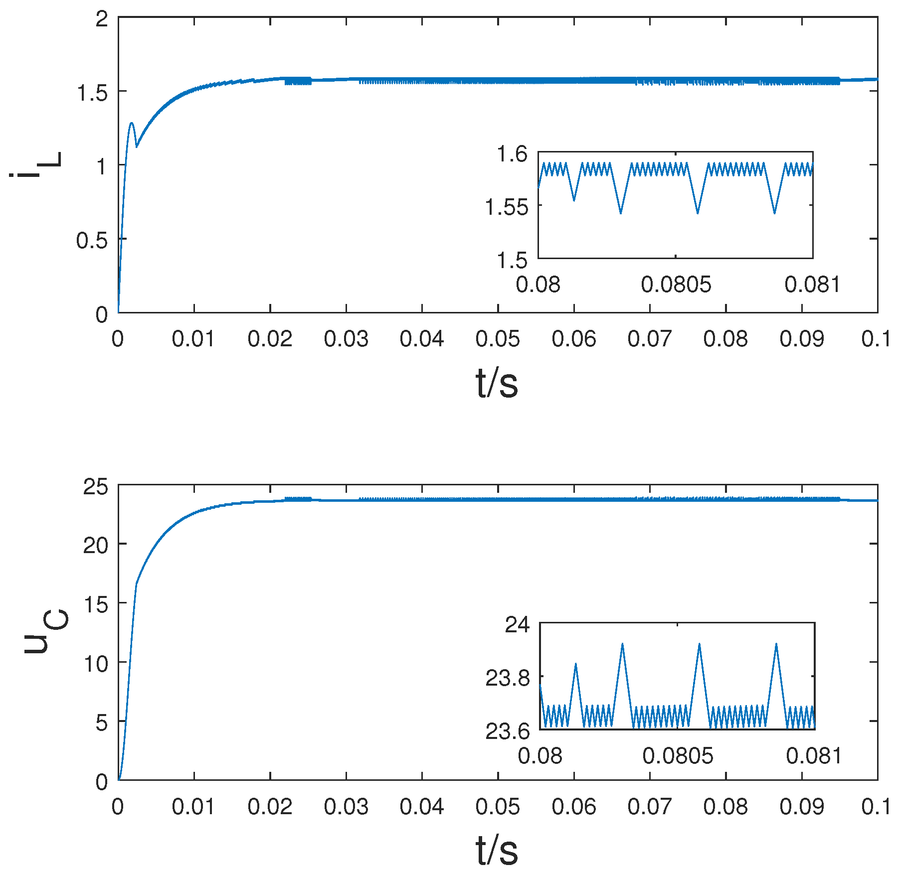
Hence, the continuous switching control law (12) is derived. Figure 4 displays the resulting state transients, confirming rapid convergence to equilibrium followed by stabilization within the bounded region (9).
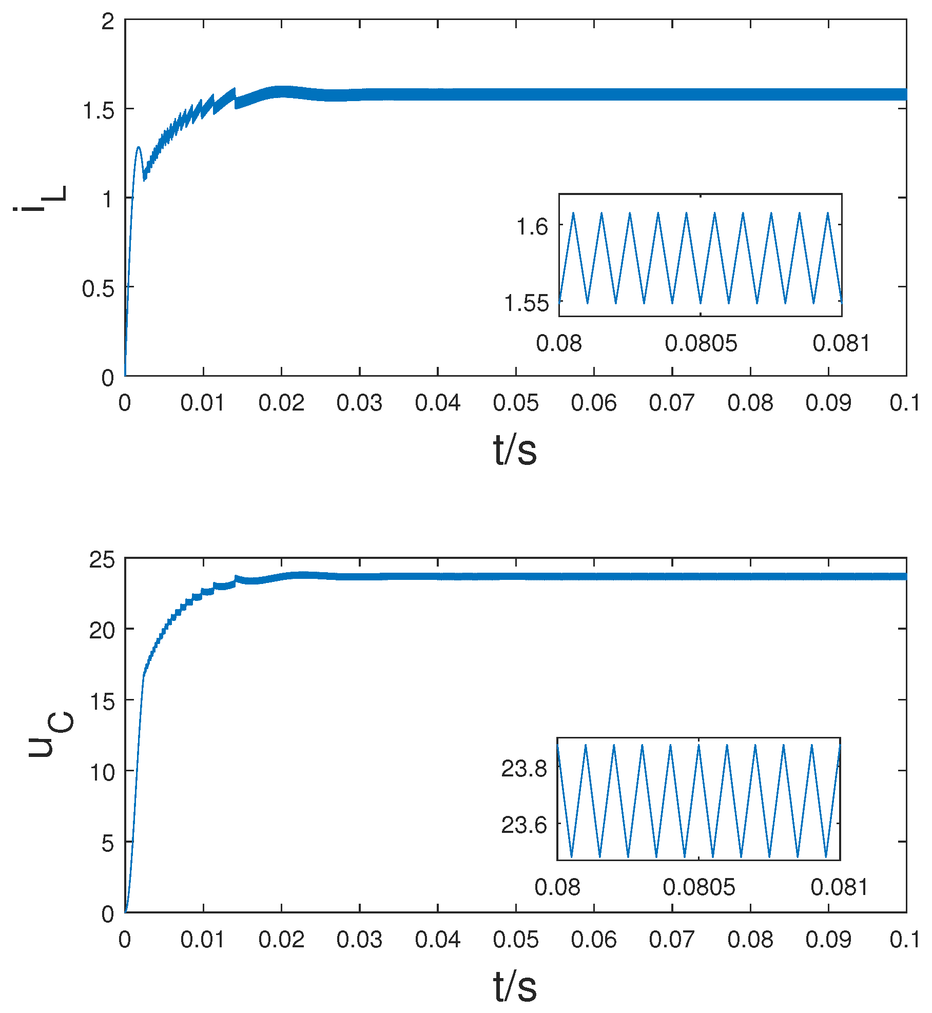
To compare the switched control strategy proposed by [23], we perform simulations and show the time responses of system states in Figure 5. The external disturbances ω ( t ) are removed during the simulation. A robust H switching rule is introduced to improve the effectiveness of the control in [23], while this paper gives out a more concise switching rule (12) to eliminate the overshoot of the steady states.
Subsequently, we evaluate the efficacy of the sampled control law (22) at a selected sampling period T = 0.05 ms. The parameters in (19) and (20) are chosen as α = 0.01 , ε 1 = 0.1 , ε 2 = 0.1 , κ = 200 , ρ = 100 and φ = 10 . By solving (19) and (20), the matrices P j , j { 1 , 2 } can be obtained as follows:
P 1 = 0.0109 4.21 × 10 5 4.21 × 10 5 1.09 × 10 4 , P 2 = 0.0086 5.21 × 10 5 5.21 × 10 5 8.55 × 10 5 ,
The switching control law (22) is then determined. Figure 6 shows the time responses of system state under the sampled control law (22). It is shown that, although the vibrations have a larger amplitude, the states can converge to the region defined by (16). Furthermore, the frequency of the ripple is lower than continuous switched control.
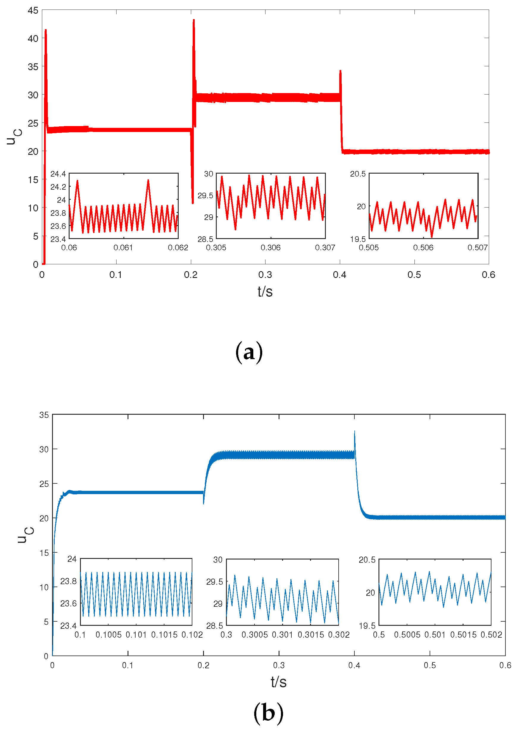
To show the tracking ability of varying reference points under the sampled control strategy (22), we change the reference point online and perform simulations. When t = 0.2 s, we change λ from 0.5 to 0.6 and when t = 0.4 s, we change λ from 0.5 to 0.4. The reference points can be calculated from (21) as
x r 1 = 1.5789 23.6842 , x r 2 = 2.4490 29.3878 , x r 3 = 1.1009 19.8165 .
To benchmark the effectiveness of the proposed method, we compare its performance with that of a classical sliding mode control (SMC) strategy under the same conditions. As shown in Figure 7, the sampled switching control strategy yields a smoother transient response with smaller overshoot and reduced fluctuations around the target values. Although the response speed is slightly slower than that of SMC, the proposed method achieves better steady-state performance and robustness to reference variations, making it more suitable for applications where smoother control is desired.
All simulations were implemented in MATLAB R2024a. LMI conditions were processed via the YALMIP toolbox with MOSEK as the underlying solver.

5. Conclusions

In this paper, the switching rule design problem of DC-DC boost converters with modeling uncertainty has been analyzed. Based on the switched model of boost converters with modeling uncertainty, continuous switching control and sampled switching control are proposed, respectively. Analysis confirms the developed control methodologies ensure closed-loop stability while satisfying established existence conditions for the control laws. Utilization of piecewise quadratic Lyapunov functions further reduces conservatism in these results. Based on the proposed strategies, the state will track a specific reference point or varying reference points in the presence of modeling uncertainty without changing the elements of the circuits. As the sampled control law is proposed considering the practical implementations, it is believed that it can be applied on a real circuit experimentally in our future research. Looking forward, the proposed control framework could be extended to other converter topologies such as buck–boost or multi-input converters, and may be further developed to handle time-varying disturbances or broader classes of uncertainties, thereby enhancing its applicability to more complex power electronic systems.

Author Contributions

Conceptualization, H.L. and X.L.; methodology, H.L.; software, H.L. and X.L.; validation, H.L. and X.L.; investigation, H.L. and X.L.; writing-original draft preparation, H.L.; writing—review and editing, H.L. and X.L. All authors have read and agreed to the published version of the manuscript.

Funding

This research received no external funding.

Data Availability Statement

Dataset available on request from the authors.

Conflicts of Interest

The authors declare no conflicts of interest.

References

  1. Middlebrook, R.D.; Cuk, S. A general unified approach to modelling switching-converter power stages. Power Electron. Spec. Conf. 1976, 1, 18–34. [Google Scholar]
  2. Renaudineau, H.; Martin, J.P.; Nahid-Mobarakeh, B.; Pierfederici, S. DC-DC converters dynamic modeling with state observer-based parameter estimation. IEEE Trans. Power Electron. 2014, 30, 3356–3363. [Google Scholar] [CrossRef]
  3. Kok, C.L.; Tang, H.; Teo, T.H.; Koh, Y.Y. A DC-DC Converter with Switched-Capacitor Delay Deadtime Controller and Enhanced Unbalanced-Input Pair Zero-Current Detector to Boost Power Efficiency. Electronics 2024, 13, 1237. [Google Scholar] [CrossRef]
  4. Zhang, J.; Li, S.; Ahn, C.K.; Xiang, Z. Sampled-data output voltage regulation for a DC-DC buck converter nonlinear system with actuator and sensor failures. Nonlinear Dyn. 2020, 99, 1243–1252. [Google Scholar] [CrossRef]
  5. Zhang, C.; Wang, J.; Li, S.; Wu, B.; Qian, C. Robust control for PWM-based DC-DC buck power converters with uncertainty via sampled-data output feedback. IEEE Trans. Power Electron. 2014, 30, 504–515. [Google Scholar] [CrossRef]
  6. Du, H.; Cheng, Y.; He, Y.; Jia, R. Finite-time output feedback control for a class of second-order nonlinear systems with application to DC-DC buck converters. Nonlinear Dyn. 2014, 78, 2021–2030. [Google Scholar] [CrossRef]
  7. Wang, J.; Li, S.; Yang, J.; Wu, B.; Li, Q. Extended state observer-based sliding mode control for PWM-based DC-DC buck power converter systems with mismatched disturbances. IET Control Theory Appl. 2015, 9, 579–586. [Google Scholar] [CrossRef]
  8. Zhang, J.; Li, S.; Ahn, C.K.; Xiang, Z. Stabilization for a class of stochastic nonlinear systems with arbitrary switching via the common Lyapunov function method. Int. J. Control Autom. Syst. 2013, 11, 926–937. [Google Scholar]
  9. He, Z.; Zhang, S.; Wu, J. Sliding mode control of switched linear systems based on common Lyapunov function. Int. Symp. Syst. Control Aeronaut. Astronaut. 2010, 300–304. [Google Scholar]
  10. Kosov, A.A.; Kozlov, M.V. On the existence and construction of common Lyapunov functions for switched discrete systems. J. Appl. Ind. Math. 2018, 12, 668–677. [Google Scholar] [CrossRef]
  11. Li, L.L.; Zhao, J.; Dimirovski, G.M. Multiple Lyapunov functions approach to observer-based H control for switched systems. Int. J. Syst. Sci. 2013, 44, 812–819. [Google Scholar] [CrossRef]
  12. Zhao, X.; Shi, P.; Yin, Y.; Nguang, S.K. New results on stability of slowly switched systems: A multiple discontinuous Lyapunov function approach. IEEE Trans. Autom. Control 2017, 62, 3502–3509. [Google Scholar] [CrossRef]
  13. Wang, R.; Hou, L.; Zong, G.; Fei, S.; Yang, D. Stability and stabilization of continuous-time switched systems: A multiple discontinuous convex Lyapunov function approach. Int. J. Robust Nonlinear Control 2019, 29, 1499–1514. [Google Scholar] [CrossRef]
  14. Zhu, Y.; Zheng, W.X. Multiple Lyapunov functions analysis approach for discrete-time switched piecewise-affine systems under dwell-time constraints. IEEE Trans. Autom. Control 2020, 65, 2177–2184. [Google Scholar] [CrossRef]
  15. Geromel, J.C.; Colaneri, P.; Bolzern, P. Dynamic output feedback control of switched linear systems. IEEE Trans. Autom. Control 2008, 53, 720–733. [Google Scholar] [CrossRef]
  16. Geromel, J.C.; Deaecto, G.S. Switched state feedback control for continuous-time uncertain systems. Automatica 2009, 45, 593–597. [Google Scholar] [CrossRef]
  17. Cui, J.; Chen, X.; Wang, R. New stability results for discrete-time switched systems: A new multiple piecewise convex Lyapunov function approach. Proc. Chin. Control Conf. 2019, 1746–1751. [Google Scholar]
  18. Wang, R.; Jiao, T.; Zhang, T.; Fei, S. Improved stability results for discrete-time switched systems: A multiple piecewise convex Lyapunov function approach. Appl. Math. Comput. 2019, 353, 54–65. [Google Scholar] [CrossRef]
  19. Deaecto, G.S.; Geromel, J.C.; Garcia, F.S.; Pomilio, J.A. Switched affine systems control design with application to DC-DC converters. IET Control Theory Appl. 2010, 4, 1201–1210. [Google Scholar] [CrossRef]
  20. Yan, X.; Shu, Z.; Sharkh, S.M. Prediction-based sampled-data control for DC-DC buck converters. In Proceedings of the 2015 First Workshop on Smart Grid and Renewable Energy (SGRE), Doha, Qatar, 22–23 March 2015; pp. 1–6. [Google Scholar]
  21. Yan, X.; Shu, Z.; Sharkh, S.M.; Wu, Z.G.; Chen, M.Z. Sampled-data control with adjustable switching frequency for DC-DC converters. IEEE Trans. Ind. Electron. 2019, 66, 8060–8071. [Google Scholar] [CrossRef]
  22. Ren, L.; Wang, D.; Yan, X.; Zhang, Y.; Wang, J. A Novel Chaotic Particle Swarm Optimized Backpropagation Neural Network PID Controller for Four-Switch Buck–Boost Converters. Actuators 2024, 13, 464. [Google Scholar] [CrossRef]
  23. Yang, Y.; Karimi, H.R.; Xiang, Z. Robust H switching rule design for boost converters with uncertain parameters and disturbances. Abstr. Appl. Anal. 2013, 2013, 120543. [Google Scholar] [CrossRef]
  24. Ahmad, S.; De Souza, R.P.C.; Kergus, P.; Kader, Z.; Caux, S. Estimation-Based Robust Switching Control of a DC-DC Boost Converter. IEEE Trans. Ind. Appl. 2025, 61, 1292–1304. [Google Scholar] [CrossRef]
  25. Xu, X.; Zhu, Y.; Wu, F.; Ahn, C.K. Sampled-Data Control for Buck-Boost Converter Using a Switched Affine Systems Approach. IEEE Trans. Circuits Syst. I Regul. Pap. 2024, 71, 3380–3389. [Google Scholar] [CrossRef]
  26. Petersen, I.R. A stabilization algorithm for a class of uncertain linear systems. Syst. Control Lett. 1987, 8, 351–357. [Google Scholar] [CrossRef]
  27. De Souza, C.E.; Li, X. Delay-dependent robust H control of uncertain linear state-delayed systems. Automatica 1999, 35, 1313–1321. [Google Scholar] [CrossRef]
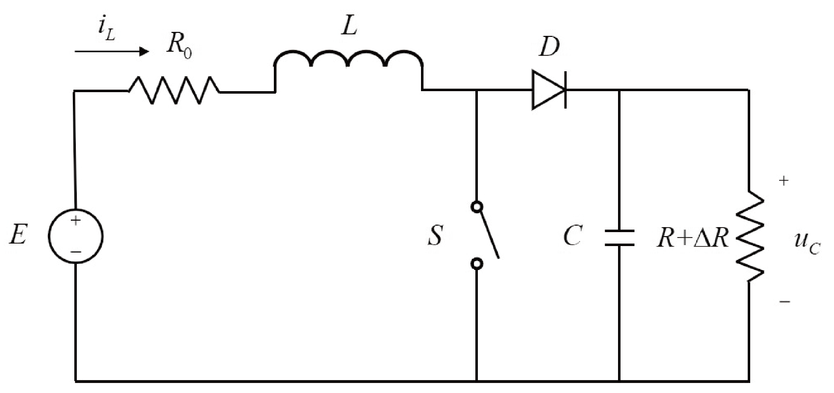
Figure 1. Topology of DC-DC boost converters.
Modelling 06 00086 g001
Figure 2. Continuous switched control system for DC-DC boost converters.
Modelling 06 00086 g002
Figure 3. Sampled switched control system for DC-DC boost converters.
Modelling 06 00086 g003
Figure 4. Time responses under switching control law (12).
Modelling 06 00086 g004
Figure 5. Time responses under the switched control proposed by [23].
Modelling 06 00086 g005
Figure 6. Time responses under the sampled switching control law (22).
Modelling 06 00086 g006
Figure 7. Time responses for the varying reference points case. (a) Sliding mode control law. (b) Sampled switching control law.
Modelling 06 00086 g007
Disclaimer/Publisher’s Note: The statements, opinions and data contained in all publications are solely those of the individual author(s) and contributor(s) and not of MDPI and/or the editor(s). MDPI and/or the editor(s) disclaim responsibility for any injury to people or property resulting from any ideas, methods, instructions or products referred to in the content.