Article

Three-Dimensional Modelling for Interfacial Behavior of a Thin Penny-Shaped Piezo-Thermo-Diffusive Actuator

1
School of Mechanical and Power Engineering, Zhengzhou University, Zhengzhou 450001, China
2
School of Mechanics and Safety Engineering, Zhengzhou University, Zhengzhou 450001, China
*
Authors to whom correspondence should be addressed.
Modelling 2025, 6(3), 78; https://doi.org/10.3390/modelling6030078 (registering DOI)
Submission received: 8 June 2025 / Revised: 17 July 2025 / Accepted: 28 July 2025 / Published: 5 August 2025

Abstract

This paper presents a theoretical model of a thin, penny-shaped piezoelectric actuator bonded to an isotropic thermo-elastic substrate under coupled electrical-thermal-diffusive loading. The problem is assumed to be axisymmetric, and the peeling stress of the film is neglected in accordance with membrane theory, yielding a simplified equilibrium equation for the piezoelectric film. By employing potential theory and the Hankel transform technique, the surface strain of the substrate is analytically derived. Under the assumption of perfect bonding, a governing integral equation is established in terms of interfacial shear stress. The solution to this integral equation is obtained numerically using orthotropic Chebyshev polynomials. The derived results include the interfacial shear stress, stress intensity factors, as well as the radial and hoop stresses within the system. Finite element analysis is conducted to validate the theoretical predictions. Furthermore, parametric studies elucidate the influence of material mismatch and actuator geometry on the mechanical response. The findings demonstrate that, the performance of the piezoelectric actuator can be optimized through judicious control of the applied electrical-thermal-diffusive loads and careful selection of material and geometric parameters. This work provides valuable insights for the design and optimization of piezoelectric actuator structures in practical engineering applications.

1. Introduction

Owing to their exceptional electromechanical coupling properties [1,2,3], piezoelectric materials are extensively employed as actuators and sensors in civil engineering and biotechnology [4,5,6,7]. When bonded to a substrate, piezoelectric sensors can transduce mechanical deformation into measurable electrical signals, enabling remote monitoring. Conversely, when an external electric field is applied to piezoelectric actuators, they generate interfacial stresses that alter the mechanical response of the substrate [8]. However, under prolonged service conditions, these induced stresses may lead to interfacial delamination, compromising the structural integrity and reliability of the system. Consequently, accurate evaluation of interfacial mechanical behavior and determination of critical failure conditions are essential for the functional design and safety assessment of piezoelectric actuator systems [9].
Extensive research has been conducted on interfacial analysis in piezoelectric actuator systems. Crawley and de Luis [10,11,12] pioneered the treatment of piezoelectric actuator structures as conventional film/substrate systems, introducing a modified Euler beam model for a thin piezoelectric actuator. Their work demonstrated that interfacial shear stress transfer occurs predominantly within an infinitesimal region near the actuator edges. Subsequent theoretical developments investigated the interfacial behavior of both perfectly and imperfectly bonded piezoelectric actuators under an applied electric voltage [13]. When electromechanical coupling effects are considered, studies reveal that while the electric field distribution remains uniform in the central region, significant field distortion occurs near the actuator extremities [14,15].
The inclusion of an adhesive layer has been shown to substantially enhance the performance of piezoelectric actuators [16], prompting numerous investigations into adhesive-bonded piezoelectric actuator systems [17,18,19]. These studies typically formulate governing integral equations for interfacial shear stress, which are subsequently solved numerically via Chebyshev polynomial expansion. Through this approach, researchers have systematically examined the effects of aspect ratio, adhesive layer properties, and material gradation parameters on interfacial behavior. Of particular concern is the phenomenon of interfacial debonding, which has been demonstrated to significantly compromise both the functional control capability and mechanical response of piezoelectric actuators [20,21]. To address this issue, layer-wise displacement models have been developed to characterize partial debonding behavior [22,23]. For advanced functional design applications, particularly those involving depth-wise functionally graded substrates, comprehensive analyses have been conducted to evaluate interfacial behavior with and without adhesive layers [24,25,26,27]. These investigations provide critical insights into the effects of substrate inhomogeneity on system performance. Recent research has increasingly focused on nonlinear response characteristics of piezoelectric actuators [28]. Advanced nonlinear models have been proposed to predict buckling behavior and axial deformation [29], enabling quantitative assessment of load transfer mechanisms between actuator and substrate. Meanwhile, the mechanical response such as bending moment, axial force, axial displacement and deflection are all determined, these developments provide valuable theoretical foundations for the design of advanced piezoelectric actuator systems.
In practical applications, piezoelectric actuators are subjected to multifield loading conditions extending beyond electrical excitation. The concurrent presence of thermal and diffusive fields significantly influences system performance, making their characterization essential for reliable design and safety evaluation. As established in the literature, elevated thermal loading induces substantial thermoelastic stresses and deformations that may precipitate interfacial delamination, necessitating rigorous thermal analysis [30]. The diffusion phenomenon, defined as the spontaneous movement of particles from a region of high concentration to low concentration, represents another critical consideration. Diffusion occurs fundamentally to the Second Law of Thermodynamics, which mandates continuous increase in system entropy over time [31,32]. The theoretical framework for these coupled phenomena was initially established through thermoelastic diffusion modeling [33], with subsequent development of a generalized theory incorporating finite wave propagation speeds with one relaxation time [34]. Further theoretical advancements extended thermo-diffusion analysis to pyroelectricity [35], and Green’s functions were derived for an orthotropic piezo-thermo-elastic diffusion (PTD) medium [36]. Recent work by Othman et al. [37,38] has focused on the gravity effect in PTD media through dual-phase-lag model and Lord-Shulman theory, providing comprehensive solutions for coupled stress, temperature and diffusion fields. Notably, despite these theoretical developments, the interfacial mechanics of PTD actuators under multifield loading remains unexplored in the literature-a critical knowledge gap given its practical significance in actuator design and reliability assessment.
Previous works are mainly focused on two-dimensional (2D) problems of piezoelectric actuators. Nevertheless, a three-dimensional (3D) model is irreplaceable in engineering applications. Therefore, it is vital to study the influence of thermal-diffusive loads in a 3D model, to the best of our knowledge, however, no related studies have been reported. Motivated by this, we aim to study the interfacial mechanical response and delamination behavior of an axisymmetric PTD actuator.
The paper is organized as follows. Section 2 describes the theoretical modal in detail, and presents the solution for a PTD actuator and an isotropic half-plane substrate. In Section 3, the integral equation is established on the basis of the perfectly bonding condition and is numerically solved by orthotropic Chebyshev polynomials. Section 4 derives the deformations, radial stresses and hoop stresses of both the PTD actuator and substrate, and the stress intensity factors (SIFs) are given as the delamination fracture criterion. Detailed results and discussion are given in Section 5. Some important conclusions are drawn in Section 6.

2. Problem Statement

Let us consider a thin PTD actuator with thickness h and radius r = a perfectly bonded to a homogeneous isotropic elastic substrate. The cylindrical coordinate system r , ϕ , z is selected so that the r o ϕ -plane is coincident with the transverse plane and the z-axis is identical to the poling direction. An electric filed Ez is applied in the z-axis by applying a voltage (V) between the upper and lower electrodes of the PTD actuator, with E z = V / h = V V + / h . In addition, a temperature load T and mass concentration C are applied along the actuator, as illustrated in Figure 1. It is important to emphasize that mass concentration, operationally defined as “the mass of a constituent per unit volume or unit mass of material”, serves as a fundamental parameter in PTD materials. This critical parameter can be modulated through several methods, including but not limited to chemical doping, photo-induced mass transport, and interfacial exchange reactions.
Compared to the thin PTD actuator with thickness h, the substrate dimensions are sufficiently large to be modeled as a semi-infinite medium. The analysis employs membrane theory, which neglects the bending stiffness of actuator. In this case, peel stresses do not build up in the direction normal to actuator, and only interfacial shear stress transfers across contact interface. The combined loads mainly result in a radial deformation. Membrane theory is a simplified theoretical framework for analyzing film-substrate structures. This theory is based on small-strain assumption, and the film is assumed to be primarily governed by in-plane stresses. Meanwhile, shear deformation along the thickness direction is ignored, with only in-plane strains and stresses considered. In most film-substrate systems, interfacial failure primarily occurs via shear failure, whereas peeling stress becomes significant only under large-curvature deformation or local debonding [17,24].

2.1. Analysis of an Axisymmetric PTD Actuator

The constitutive equations of a transversely isotropic piezo-thermo-diffusive actuator are given in the cylindrical coordinate system as [36]
σ r r = c 11 u r r + c 12 1 r u ϕ ϕ + u r r + c 13 u z z e 31 E z β 1 T b 1 C ,
σ ϕ ϕ = c 11 1 r u ϕ ϕ + u r r + c 12 u r r + c 13 u z z e 31 E z β 1 T b 1 C ,
σ z z = c 13 u r r + 1 r u ϕ ϕ + u r r + c 33 u z z e 33 E z β 3 T b 3 C ,
D r = e 15 u r z + u z r + e 11 E r ,
D z = e 31 u r r + e 33 u z z + e 33 E z + p 3 T ,
where ui, σij, and Di are respectively the components of displacement, stress, and electric displacement; Ei, T, and C are electric field, temperature increment, and mass concentration, respectively; cij, eij, e i j , p3, βi, and bi are elastic, piezoelectric, dielectric, pyroelectric, thermal and diffusion constants, respectively.
In the absence of body forces, heat sources and concentration sources, equilibrium equations of the PTD actuator can be expressed as [36]
σ r r r + 1 r σ r ϕ ϕ + σ r r σ ϕ ϕ r + σ z r z = 0 ,
σ r ϕ ϕ + 1 r σ ϕ ϕ ϕ + 2 σ r ϕ r + σ z ϕ ϕ = 0 ,
σ z r r + 1 r σ z ϕ ϕ + σ z r r + σ z z z = 0 ,
D r r + D r r + D z z = 0 ,
λ 1 2 r 2 + 1 r 2 r ϕ + 1 r 2 2 ϕ 2 + λ 3 2 z 2 T = 0 ,
γ 1 2 r 2 + 1 r 2 r ϕ + 1 r 2 2 ϕ 2 + γ 3 2 z 2 C = 0 ,
where λi and γi are the thermal conductivity and diffusion parameters, respectively.
In the following discussion, the superscript “a” and “s” denote to the PTD actuator and the substrate, respectively. The symmetry conditions of the geometry and the loading permits to seek an axisymmetric solution type, all the stress components should be independent on the variable ϕ, and we have [39]
σ z ϕ a = σ z z a = 0 ,   for       0 < r < a
In addition, the stress component σ r ϕ a is nonexistent and the stress component σ ϕ ϕ a remains the same value in the hoop direction due to the symmetry. In addition, only the interfacial shear stress τ, i.e., σ r z a , dominates the interfacial behavior of the axisymmetric film/substrate structure. Therefore, the equilibrium of forces along r-direction can be rewritten as
σ r r a r + σ r r a σ ϕ ϕ a r τ h = 0 .
Inserting Equation (1c) into Equation (3) and recalling that the problem is non-axisymmetric, we have the following relation
u z z = c 13 c 33 u r r + u r r + e 33 E z + β 3 T + b 3 C c 33 .
Substituting Equation (5) into Equation (1a) yields
σ r r a r = 1 u r r + 2 u r r 1 E z 2 T 3 C ,
σ ϕ ϕ a r = 2 u r r + 1 u r r 1 E z 2 T 3 C ,
where i and i are respectively the effective Young’s modulus and electrical, thermal and diffusive constants for PTD actuator with their definitions given by
1 = c 11 c 13 2 / c 33 ,                 2 = c 12 c 13 2 / c 33 ,
1 = e 31 c 13 c 33 e 33 ,       2 = β 1 c 13 c 33 β 3 ,           3 = b 1 c 13 c 33 b 3 .
Substituting Equation (6) into Equation (4) and integrating with respect to r leads to
u r a r + u r a r = 1 1 h 0 r τ t d t + 1 1 E z + 2 1 T + 3 1 C + d 0 ,
where the constant d0 is determined by the boundary conditions.

2.2. Analysis of an Isotropic Elastic Substrate

The substrate is assumed to be thermally conducted while electrically and diffusively insulated. The axisymmetric constitutive equations of an isotropic thermo-elastic substrate can be expressed as
σ r r s = λ + 2 μ u r s r + λ u r s r + λ u z s z α T ,
σ ϕ ϕ s = λ u r s r + λ + 2 μ u r s r + λ u z s z α T ,
σ z z s = λ u r s r + λ u r s r + λ + 2 μ u z s z α T ,
σ z r s = μ u r s z + u z s r ,
where α is the thermal modulus, λ and μ are respectively the Lamé constant and shear modulus which are in the following forms
λ = E v 1 + v 1 2 v ,                   μ = E 2 1 + v ,
where E and v are the Young’s modulus and Poisson’s ratio of the substrate, respectively.
Besides, the governing equations for the axisymmetric problem can be written as
σ r r s r + σ r r s σ ϕ ϕ s r + σ z r s z = 0 ,
σ z r s r + σ z r s r + σ z z s z = 0 ,
2 r 2 + 2 z 2 T = 0 .
According to the general solution for an isotropic thermo-elastic material [40], one obtains the completed non-torsional axisymmetric general solution around the z-axis in terms of potential functions ψ i as
2 μ u r s = ψ 1 r + z ψ 2 r ,
2 μ u z s = ψ 1 z 3 4 v ψ 2 + z ψ 2 z + 4 1 v ψ 3 ,
2 μ Γ T = ψ 3 z ,
σ r r s = 2 ψ 1 r 2 2 v ψ 2 z + z 2 ψ 2 r 2 2 1 v ψ 3 z ,
σ z z s = 2 ψ 1 z 2 2 1 v ψ 2 z + z 2 ψ 2 z 2 + 2 1 v ψ 3 z ,
σ z r s = 2 ψ 1 r z 1 2 v ψ 2 r + z 2 ψ 2 r z + 2 1 v ψ 3 r ,
where Γ = 2 λ + 2 μ / α is the material-related constant, and ψ i satisfy harmonic relations. Using the Hankel transform to the potential functions as
ψ j r , z = 0 A j e ξ z J 0 ξ r d ξ ,     for     j = 1 , 2 , 3 ,
where ξ is the Hankel transform parameter, and Aj are the coefficients to be determined by surface boundary conditions. As the peeling stress between the film and the substrate is neglected, the surface traction condition is given as
σ z z s r , 0 = 0 ,         σ z r s r , 0 = τ r .
Keep in mind that for Hankel transform y r = 0 ξ y ¯ ξ J 0 ξ r d ξ , its reverse transform is y ¯ ξ = 0 r y r J 0 ξ r d r . Inserting Equation (13) into Equations (12) and (14) yields
A 1 ξ 2 1 v A 2 + 2 1 v A 3 = 0 , A 1 ξ 1 2 v A 2 + 2 1 v A 3 = 0 r τ r J 1 ξ r d r , A 3 e ξ z = 2 μ Γ T 0 r J 0 ξ r d r .
After solving Equation (15), one obtains
A 1 ξ = 2 1 v 0 t τ t J 1 ξ t d t + 2 μ Γ e ξ z T 0 t J 0 ξ t d t ,
then the radial displacement on the surface of the substrate is obtained as
u r s r , 0 = 1 v μ 0 0 t τ t J 1 ξ t d t + 2 μ Γ T 0 t J 0 ξ t d t J 1 ξ r d ξ ,
which can be rewritten as
u r s r , 0 = 1 v μ 0 a 0 J 1 ξ t J 1 ξ r d ξ t τ t d t + 2 1 v Γ T 0 a 0 J 0 ξ t J 1 ξ r d ξ t d t .
Equation (18) can be further calculated as
u r s r , 0 = 1 v μ 0 a H 11 t , r t τ t d t + 2 1 v Γ T 0 a H 12 t , r t d t ,
where the arisen functions H 1 j are defined as
H 11 t , r = 0 J 1 ξ t J 1 ξ r d ξ , H 12 t , r = 0 J 0 ξ t J 1 ξ r d ξ .
According to the property of Bessel functions, Equation (20) can be expressed as
H 11 t , r = 2 π K t / r E t / r / t , for t r , K r / t E r / t / r , for t r ,
H 12 t , r = 1 / r , for t < r , 1 / 2 r , for t = r , 0 , for t > r ,
where the functions K x and E x are respectively the complete elliptic integrals of the first and second kind. Substituting Equation (21b) into Equation (19) yields
u r s r , 0 = 1 v μ 0 a H 11 t , r t τ t d t + 1 v Γ T r .

3. The Governing Integral Equation

The perfect bonding condition between the actuator and the substrate leads to
u r a r , 0 = u r s r , 0 ,         for     0 r a .
Substituting Equations (8) and (22) into Equation (23) yields
0 a F t , r t τ t d t D 0 h 0 r τ t d t = D 1 E z + D 2 T + D 3 C + D 4 ,
where
F t , r = H 11 t , r r + H 11 t , r r ,
D 0 = μ 1 v 1 ,       D 1 = μ 1 1 v 1 ,     D 2 = μ 2 1 v 1 2 Γ ,
D 3 = μ 3 1 v 1 ,       D 4 = μ 1 v d 0 .
After mathematical derivation, the function F t , r can be further written as
F t , r = 2 π 1 r t K t r + r t t 2 r 2 E t r , for t < r 1 t 2 r 2 E r t , for t > r
For small a value of t r , the singularity of the kernel function F t , r can be extracted as [39]
t F t , r = 1 π 1 t r + 1 t + r + M t , r 1 t r + M t , r 1 t + r ,
where
M t , r = t 2 r 2 r t K t r + r t E t r , for t < r E r t , for t > r
It should be noted that [41]
M t , r 1 t r 1 2 r ln t r ,
thus the integral Equation (24) can be rewritten as
1 π 0 a 1 t r + 1 t + r 1 2 r ln t r + N t , r τ t d t D 0 h 0 r τ t d t = D 1 E z + D 2 T + D 3 C + D 4 ,
where
N t , r = M t , r 1 t r + M t , r 1 t + r + 1 2 r ln t r .
Equation (30) is a singular integral equation with a Cauchy kernel, thus the interfacial shear stress exhibits a square root singularity near the film edge [42]. As is noted, the constant D4 has not yet been determined as d0 is not given. The integral constant d0 can be determined from the additional traction boundary condition at the actuator front by combining Equations (6a), (8) and (22) as
σ r r a a = 1 h 0 a τ t d t + c 12 c 11 1 v μ a 0 a H 11 t , a t τ t d t + 1 d 0 + c 12 c 11 1 v Γ T = 0 .
Then, the constant D4 can be obtained as
D 4 = μ 1 v 1 1 h 0 a τ t d t + c 11 c 12 1 v μ a 0 a H 11 t , a t τ t d t + c 11 c 12 1 v Γ T .
Inserting Equation (33) into Equation (30) yields the final governing integral equation for interfacial shear stress τ as
1 π 0 a 1 t r + 1 t + r 1 2 r ln t r + N t , r τ t d t D 0 h 0 r τ t d t μ 1 v 1 h 0 a τ t d t c 11 c 12 1 a 0 a H 11 t , a t τ t d t = D 1 E z + D 2 T + D 3 C + c 11 c 12 1 Γ T .
Introducing the normalized quantities
r = a ζ , t = a η , N ^ ζ , η = a N r , t , τ ^ = τ r / τ 0 ,
τ 0 = D 1 E z + D 2 + c 11 c 12 1 Γ T + D 3 C ,
Equation (34) can be rewritten as
1 π 0 1 1 η ζ + 1 η + ζ 1 2 ζ ln ζ η + N ^ ζ , η τ ^ η d η a D 0 h 0 ζ τ ^ η d η μ a 1 v 1 h 0 1 τ ^ η d η 2 c 11 c 12 π 1 0 1 K η E η τ ^ η d η = 1 .
The integral equation in Equation (36) cannot be solved analytically. According to the singularity and characteristic of the integral, the interfacial shear stress τ can be expressed in terms of orthogonal Chebyshev polynomials as [43,44]
τ η = η 1 η j = 0 b j L j m ,
where bj is the unknown coefficients to be determined, and
L j m = T j m + T j + 1 m 1 + m ,
in which m = 2 η 1 , and T j m is the Chebyshev polynomials of the first kind.
During the solution of Equation (36), the following properties of the Chebyshev polynomials can be used [41]
I 1 j ζ = 1 π 0 1 η 1 η L j 2 η 1 η ζ d η = U 0 2 ζ 1 , j = 0 U j 1 2 ζ 1 + U j 2 ζ 1 , j 1 ,
I 2 j ζ = 1 π 0 1 η 1 η L j 2 η 1 η + ζ d η = 1 2 π 0 1 η 1 η T j 2 η 1 + T j + 1 2 η 1 η η + ζ d η ,
I 3 j ζ = 1 π 1 2 ζ 0 1 ln ζ η η 1 η L j 2 η 1 d η = 1 4 ζ T 1 2 ζ 1 + 2 ln 2 , j = 0 T j 2 ζ 1 j + T j + 1 2 ζ 1 j + 1 , j 1 ,
I 4 j ζ = 1 π 0 1 η 1 η L j 2 η 1 N ^ ζ , η d η ,
I 5 j ζ = 0 ζ η 1 η L j 2 η 1 d η = 1 2 U 0 2 ζ 1 1 2 ζ 1 2 π + arccos 2 ζ 1 , j = 0 U j 1 2 ζ 1 j + U j 2 ζ 1 j + 1 1 2 ζ 1 2 , j 1 ,
I 6 j = 0 1 η 1 η L j 2 η 1 d η = π 2 , j = 0 0 , j 1 ,
I 7 j = 0 1 K η E η η 1 η L j 2 η 1 d η ,
where U j m is the Chebyshev polynomials of the second kind. Then the discretized form of the integral Equation (36) can be rewritten as
j = 0 b j I 1 j + I 2 j + I 3 j + I 4 j a D 0 h I 5 j μ a 1 v 1 h I 6 j 2 c 11 c 12 π 1 I 7 j = 1 .
Finally truncating the series in Equation (40) to have a finite number of N + 1 terms, the collocation points along PTD actuator can be properly selected as
ζ k = 1 2 1 + cos π 2 k 1 2 N + 1 , k = 1 , 2 , , N + 1
Then, Equation (40) can be rewritten as the N + 1 linear algebraic equations, corresponding to N + 1 unknown coefficients bj as
j = 0 N b j I 1 j ζ k + I 2 j ζ k + I 3 j ζ k + I 4 j ζ k a D 0 h I 5 j ζ k μ a 1 v 1 h I 6 j 2 c 11 c 12 π 1 I 7 j = 1 , for k = 1 , , N + 1
After solving Equation (42), one can get all the coefficients bj. Thus, the interfacial shear stress of the PTD actuator is obtained as
τ t = τ 0 η 1 η j = 0 N b j L j m .

4. Other Quantities of Interest

As the shear stress is determined, keep in mind that r u r a r = r u r a r + u r a r , one can get the radial displacement u r r by integrating Equation (8) as
u r r a = 2 π 1 v μ τ 0 0 ζ K η ζ E η ζ τ η d η + ζ 1 η ζ K ζ η E ζ η τ η d η + 1 v Γ T ζ + d r ,
where τ 0 has been defined in Equation (35), and the constant dr can be determined from the additional condition
lim r 0 u r r = 0 .
Meanwhile, the radial and hoop stresses of PTD actuator can be obtained as
σ r r a r = 1 h 0 r τ t d t + c 12 c 11 u r r + 1 d 0 ,
σ ϕ ϕ a r = 1 h 0 r τ t d t + c 11 c 12 u r r + 2 d 0 ,
which can be rewritten as
σ r r a r = 1 h 0 r τ t d t 0 a τ t d t c 11 c 12 1 v μ 1 r 0 a H 11 t , r t τ t d t 1 a 0 a H 11 t , a t τ t d t ,
σ ϕ ϕ a r = 2 1 1 h 0 r τ t d t 0 a τ t d t + c 11 c 12 1 v μ T 1 + 2 1 + c 11 c 12 1 v μ 1 r 0 a H 11 t , r t τ t d t + 1 a 2 1 0 a H 11 t , a t τ t d t 1 2 1 1 E z + 2 T + 3 C ,
and the normalized expressions are
σ r r a r τ 0 = a h 0 ζ τ ^ η d η 0 1 τ ^ η d η c 11 c 12 2 π 1 v μ 1 ζ 0 ζ K η ζ E η ζ τ η d η + ζ 1 η ζ 2 K ζ η E ζ η τ η d η 0 1 K η E η τ η d η ,
σ ϕ ϕ a r τ 0 = 2 1 a h 0 ζ τ ^ η d η 0 1 τ ^ η d η + c 11 c 12 1 v μ τ 0 T 1 + 2 1 + c 11 c 12 1 v μ τ 0 1 ζ 0 ζ K η ζ E η ζ τ η d η + ζ 1 η ζ 2 K ζ η E ζ η τ η d η 2 1 0 1 K η E η τ η d η 1 2 1 1 E z + 2 T + 3 C τ 0 .
Moreover, considering the peel stress neglected, i.e., σ z z s r , 0 = 0 , one can obtain the vertical strain on the surface of the substrate from Equation (9c) as
u z s z = λ λ + 2 μ u r s r + u r s r + α T λ + 2 μ .
Inserting Equation (49) into Equation (9a,b), one gets the radial and hoop stresses of the upper surface of substrate as
σ r r s r , 0 = 4 μ λ + μ λ + 2 μ u r r + u r r 2 μ u r r 2 μ λ + 2 μ α T ,
σ ϕ ϕ s r , 0 = 2 λ μ λ + 2 μ u r r + u r r + 2 μ u r r 2 μ λ + 2 μ α T .
Substituting Equations (8), (22), (25) and (33) into Equation (50) yields the normalized expressions for the radial and hoop stresses of the upper surface of substrate as
σ r r s r τ 0 = a 1 h 4 μ λ + μ λ + 2 μ 0 ζ τ ^ η d η 0 1 τ ^ η d η + c 11 c 12 8 λ + μ λ + 2 μ 1 v π 1 0 1 K η E η τ η d η 4 π 1 v 1 ζ 0 ζ K η ζ E η ζ τ η d η + ζ 1 η ζ K ζ η E ζ η τ η d η 2 μ 1 v τ 0 Γ T + c 11 c 12 1 v τ 0 Γ 1 4 μ λ + μ λ + 2 μ T 2 μ λ + 2 μ α T τ 0 4 μ λ + μ λ + 2 μ 1 1 E z + 2 T + 3 C τ 0 ,
σ ϕ ϕ s r τ 0 = a 1 h 2 λ μ λ + 2 μ 0 ζ τ ^ η d η 0 1 τ ^ η d η + c 11 c 12 4 λ μ λ + 2 μ 1 v π μ 1 0 1 K η E η τ η d η + 4 π 1 v 1 ζ 0 ζ K η ζ E η ζ τ η d η + ζ 1 η ζ K ζ η E ζ η τ η d η + 2 μ 1 v τ 0 Γ T + c 11 c 12 1 v τ 0 Γ 1 2 λ μ λ + 2 μ T 2 μ λ + 2 μ α T τ 0 2 λ μ λ + 2 μ 1 1 E z + 2 T + 3 C τ 0 .
According to Equations (35), (44), (48) and (51), the normalization τ 0 depends on the material constants and is strongly determined by the applied electric voltage, temperature change, and mass concentration. Meanwhile, all the displacements and stresses show a linear relation with the normalization τ 0 . This solution allows regulation and control of the mechanical response by adjusting the applied voltage when the structure is placed in a certain temperature and mass concentration environment. As the asymptotic behavior of the shear stress near the edge of the actuator can be interpreted as a measure of edge debonding failure mechanism, the Mode II SIF can be defined as
K II a = lim r a 2 π a r τ r .
Inserting Equations (35) and (37) into Equation (52) and considering the property of Chebyshev polynomials, the SIF can be calculated as
K II a = 2 π a τ 0 j = 0 N b j .

5. Results and Discussion

To systematically examine the factors governing the interfacial behavior of the PTD actuator, a series of numerical simulations were conducted. For conciseness while maintaining generality, all stresses, displacements and SIFs were normalized by τ 0 , a, and τ 0 a , respectively. Cadmium selenide (CdSe), a representative II–VI compound semiconductor, exhibits exceptional piezoelectric performance and pronounced ionic diffusion capabilities. These distinctive properties endow CdSe with significant potential for diverse applications spanning sensor technologies, energy devices and environmental monitoring systems. Consequently, CdSe was selected as the PTD material in this study, with its complete material constants referenced from [36]. Three typical substrate materials, i.e., copper (Cu), zirconium dioxide (ZrO2), and silicon (Si) were investigated, and their material properties are listed in Table 1.
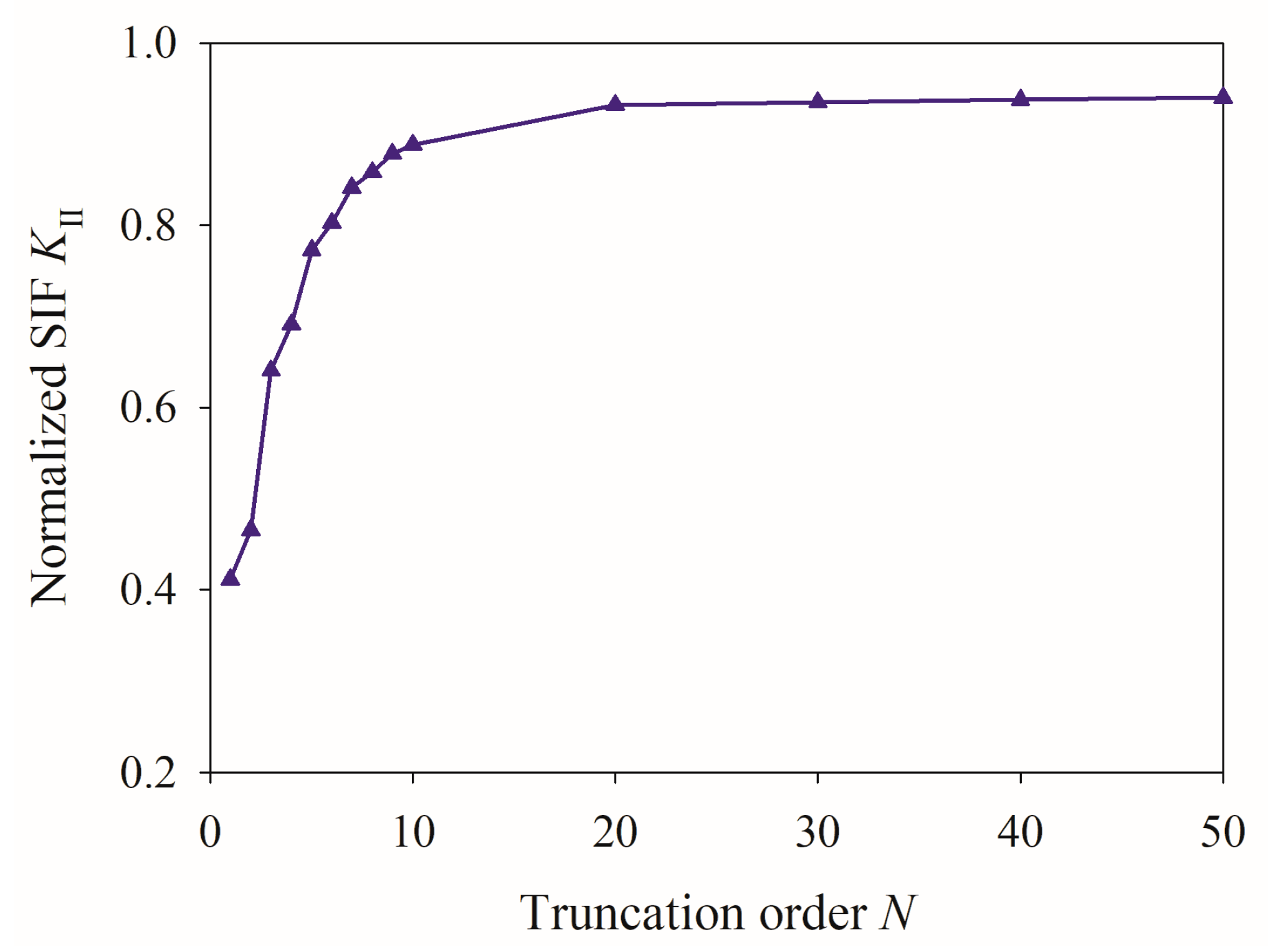
The selection of the truncation order N critically influences the reliability and computational accuracy of the calculation. As illustrated in Figure 2, the SIF converges to a stable value once N exceeds 20. To ensure high numerical precision, a truncation order of N = 40 was adopted in subsequent computations.

5.1. Influence of Aspect Ratio

At first, the influence of aspect ratio is discussed, and the substrate material is fixed as Cu. As depicted in Figure 3, the interfacial shear stress nearly vanishes in the center of the actuator while increases monotonically along the radial direction. An obvious singularity emerges near the actuator edge, which serves as the likely initiation site for interfacial delamination. Notably, thicker actuator induces higher shear stress magnitudes, suggesting an increased propensity for debonding compared to their thinner counterparts.
Figure 3 also demonstrates that, the analytical results coincide well with finite element (FE) simulations by COMSOL Multiphysics 3.5a, particularly at higher aspect ratio. The minor discrepancies observed arise from inherent model simplifications, i.e., the present theoretical framework employs membrane theory under axisymmetric assumptions, effectively reducing the problem to a quasi-1D formulation, whereas the FE analysis retain full 3D resolution. This comparison confirms that the membrane approximation remains valid for high aspect ratio configurations.
In the FE simulation was performed using a 3D axisymmetric model implemented in COMSOL’s PDE module. The computational domain comprised over 40,000 hexahedral elements, yielding approximately 1.2 million degrees of freedom. Perfect bonding conditions were enforced at interfaces, with hexahedral elements maintained throughout the domain boundaries (see Figure 4). Convergence studies verified mesh independence, and the truncated outer boundary was set at eight times the film radius (R = 8a). remarkably, while the analytical solution required only 40 collocation points to achieve sufficient accuracy, it demonstrated significantly lower computational expense compared to the full 3D FE simulation.
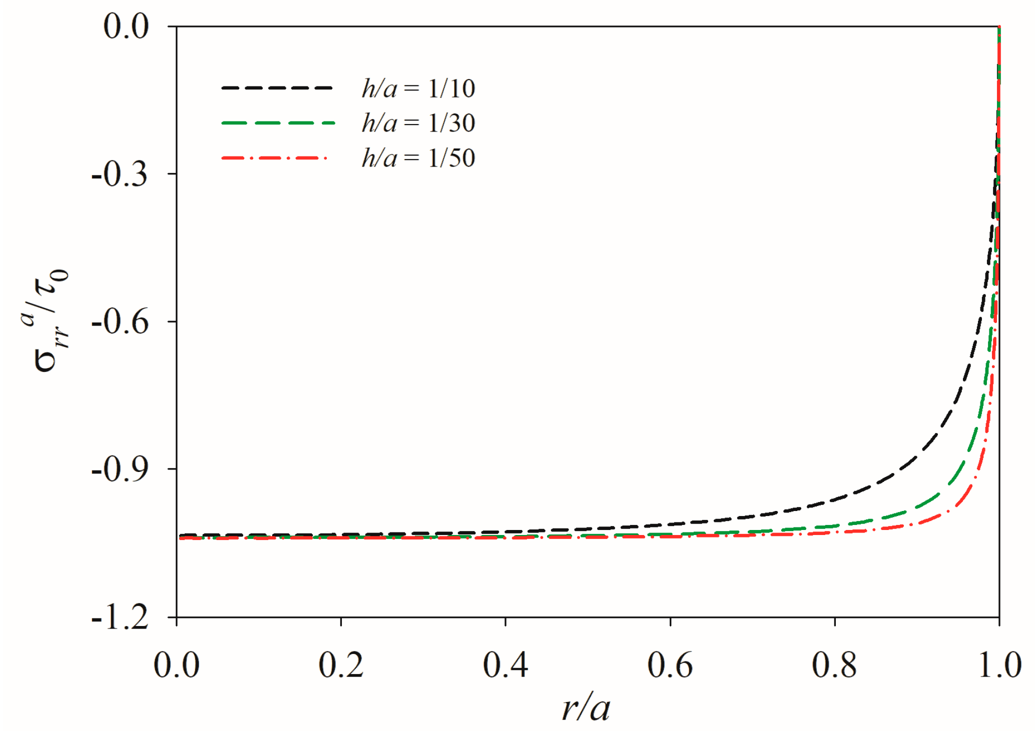
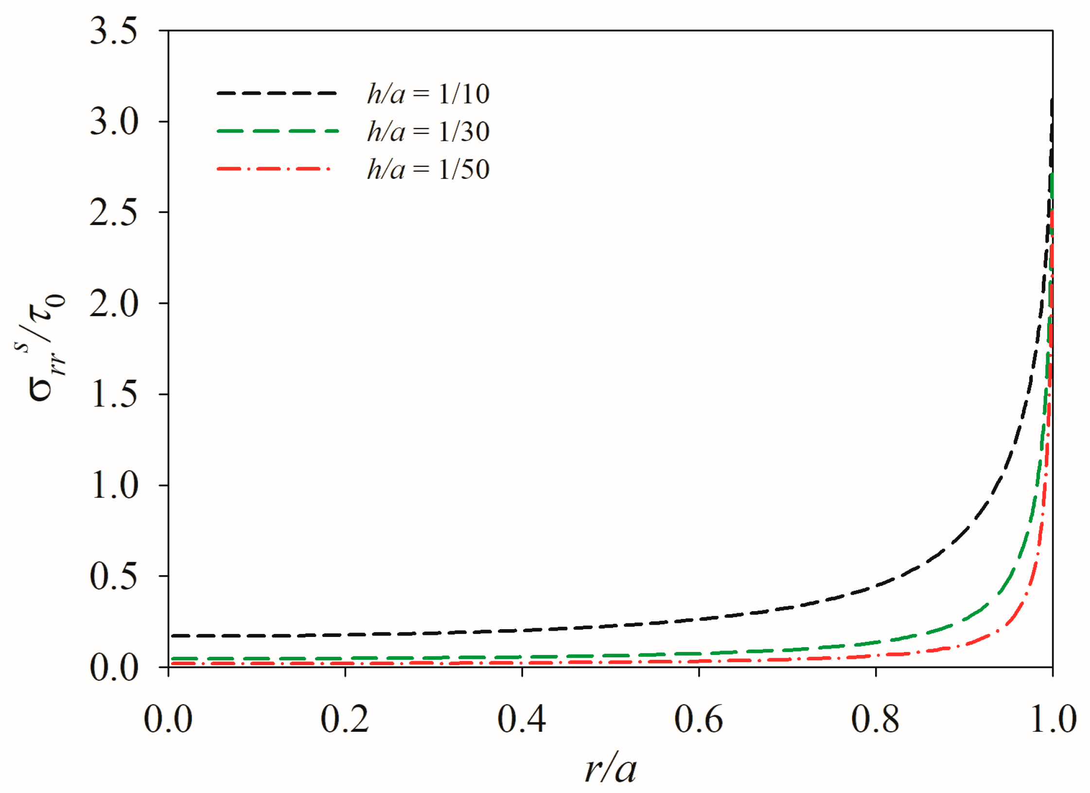
The radial displacement shows an obvious distribution in the actuator, and a thicker actuator possesses a larger radial displacement (see Figure 5). It is easy to find that the absolute value of the radial stress and hoop stress are almost constant in the center of the actuator, and then the radial stress starts to decrease and tends to zero at the film front, which agrees well with the free traction boundary condition at the film edge, while the hoop stress increases to a certain value at the actuator edge (see Figure 6 and Figure 7). At the same time, a thinner actuator possesses a larger radial stress and less hoop stress. It is readily observed from Figure 8 and Figure 9 that, the variation trend of stresses at the surface of the substrate is quite opposite to that in the actuator, and a thicker actuator induces larger values of radial stress and hoop stress. Therefore, designing a thinner axisymmetric PTD actuator can greatly alleviate the failure risk of the substrate near the edge of the actuator.

5.2. Influence of Material Mismatch

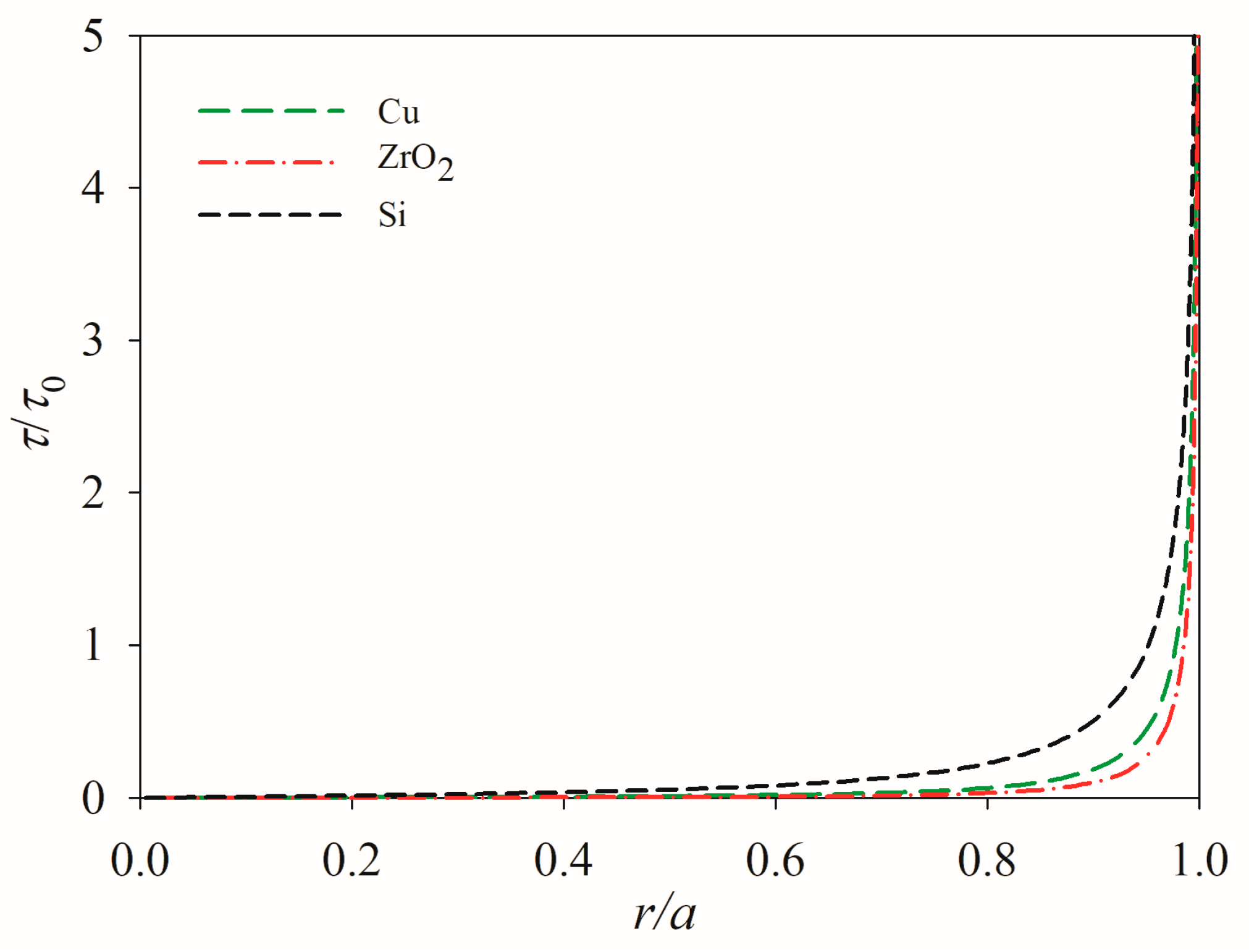
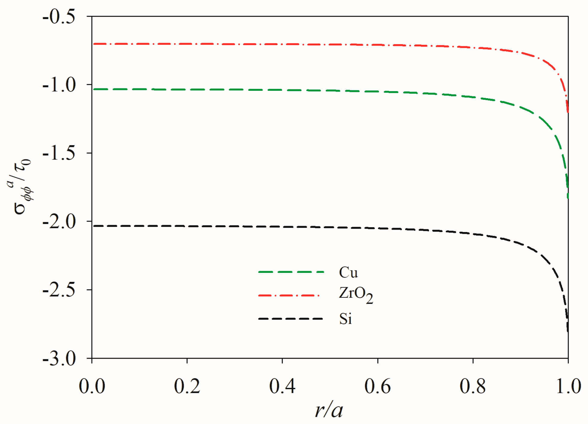
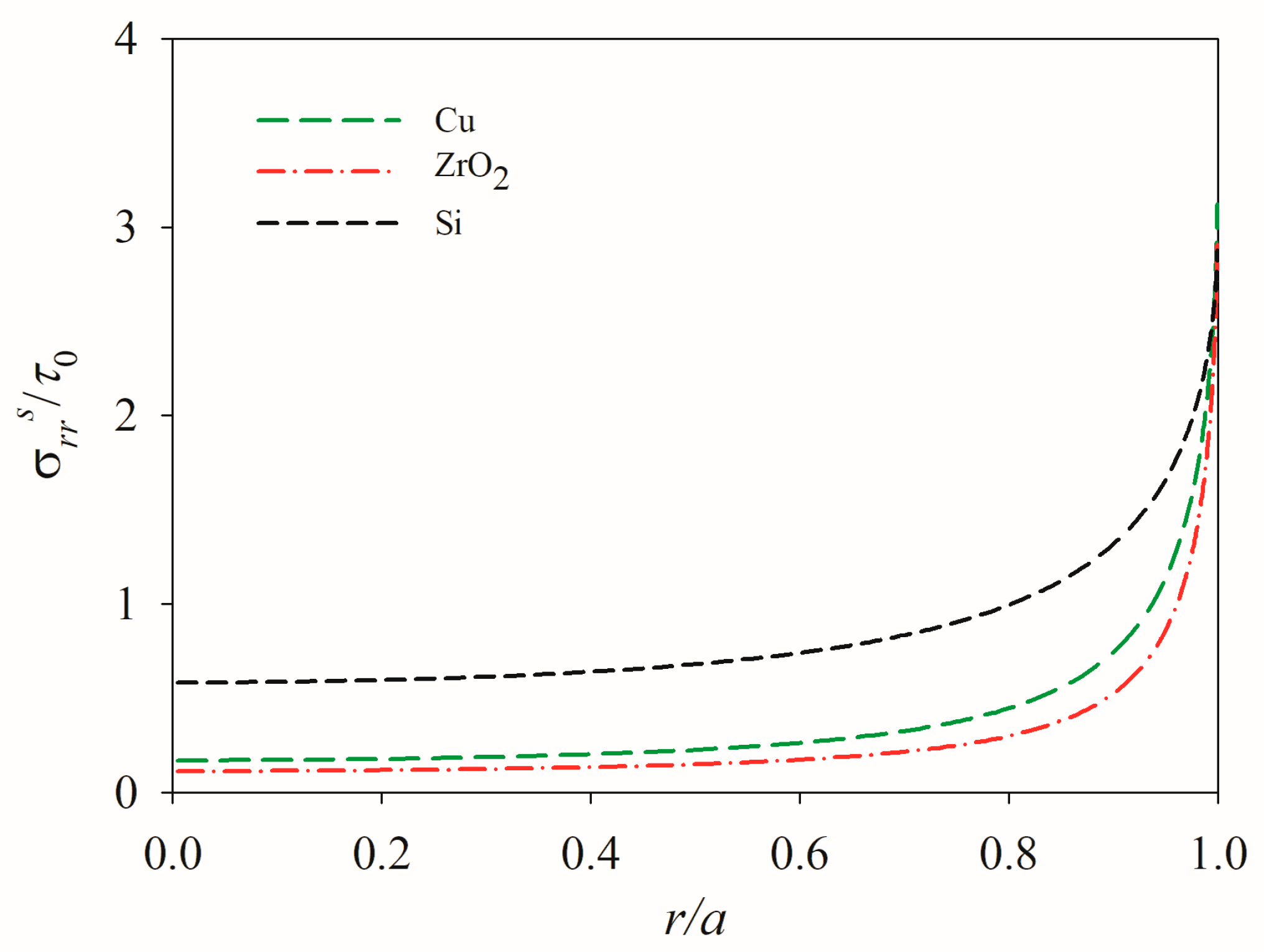
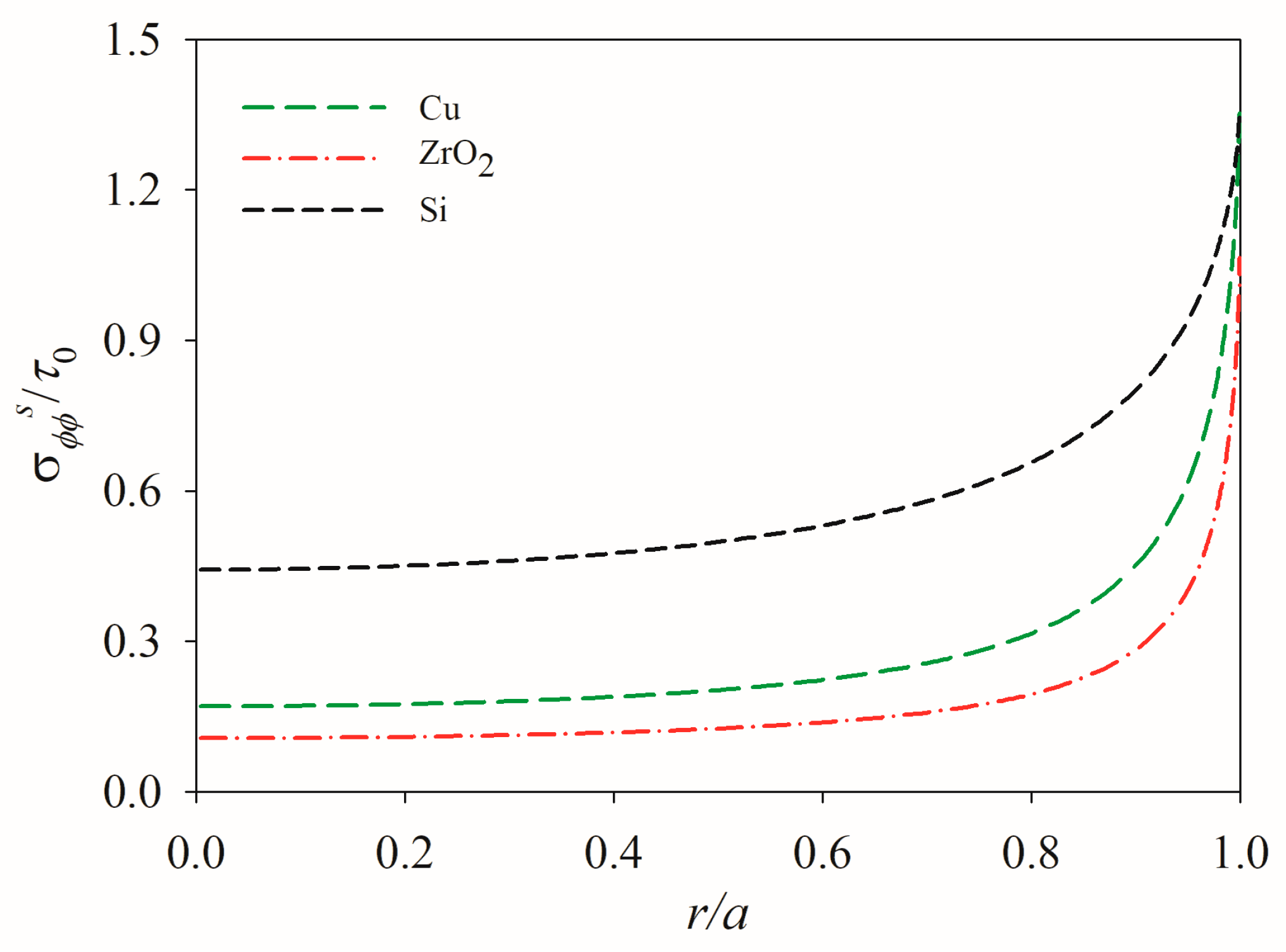
As illustrated in Figure 10, different substrate materials have great influence on the interfacial shear stress. Based on the governing integral equation in Equation (36), the influencing factors of material mismatch are dependent on material constants of PTD actuator and substrate. For a fixed PTD material, the influencing factor of substrate material is mainly related to a comprehensive parameter β s = μ / 1 v . A lower value of β s leads to a higher level of interfacial shear stress. As the radial displacement, radial stress and hoop stress are all related to the shear stress, a substrate with lower value of β s possesses larger displacement and stresses (see Figure 11, Figure 12, Figure 13, Figure 14 and Figure 15). Therefore, selecting a substrate with lower β s can reduce the level of stresses and enhance the bonding strength. Figure 16 shows that, increasing the film thickness and value of β s will enlarge the value of stress intensity factor and eventually lead to delamination.

6. Conclusions

A thin axisymmetric PTD actuator was analyzed under electrical–thermal–diffusive loads based perfect bonding condition. The integral equation was established in terms of interfacial shear stress. The integral equation was numerically solved by Chebyshev polynomials. Delamination behavior was studied using the fracture parameter of stress intensity factor. The membrane theory approximation adopted in this study renders the solution particularly suitable for high aspect ratio configuration (a/h >>1). For cases where bending moment and peeling stresses become non-negligible, higher-order theories (e.g., beam or plate theories) would be required for accurate modeling. The following important conclusions are drawn.
  • The proposed analytical model effectively captures the mechanical response of an axisymmetric PTD actuator. Numerical results reveal that interfacial shear stress concentration near the actuator edge periphery governs delamination initiation.
  • The total strain exhibits linear dependence on applied multi-physical loads while being modulated by material properties. This linearity enables precise control of mechanical response through load parameter manipulation.
  • Both material properties and geometric factors significantly influence the mechanical performance. Specifically, thicker PTD actuators bonded to substrates with lower stiffness ratios are more susceptible to edge debonding.
The present work provides fundamental insights into the intrinsic relationships between mechanical performance, material properties, and geometric parameters in PTD systems. Compared with FE simulations, the proposed method offers substantial computational efficiency while maintaining satisfactory accuracy. These findings contribute valuable theoretical foundations for both functional design optimization and failure mode assessment in PTD actuator systems.

Author Contributions

H.Z. Conceptualization, methodology investigation, data curation, and writing-original draft preparation; L.Z.: Resources, visualization, supervision, and project administration; H.-Y.D.: Validation, supervision, and writing—review and editing. All authors have read and agreed to the published version of the manuscript.

Funding

This research was supported by the Zhongyuan Academician Foundation (ZYQR2019120188).

Data Availability Statement

The raw data supporting the conclusions of this article will be made available by the authors on request.

Conflicts of Interest

The authors declare no conflicts of interest.

References

  1. Wang, J.H.; Lv, C.Q.; Liu, T.Y. Indentation response of piezoelectric films. J. Mech. Phys. Solids 2008, 56, 3331–3351. [Google Scholar] [CrossRef]
  2. Dagdeviren, C.; Shi, Y.; Joe, P.; Ghaffari, R.; Balooch, G.; Usgaonkar, K.; Gur, O.; Tran, P.L.; Crosby, J.R.; Meyer, M.; et al. Conformal piezoelectric systems for clinical and experimental characterization of soft tissue biomechanics. Nat. Mater. 2015, 14, 728–736. [Google Scholar] [CrossRef]
  3. Jiao, P.; Egbe, K.J.I.; Xie, Y.; Matin Nazar, A.; Alavi, A.H. Piezoelectric sensing techniques in structural health monitoring: A static-of-the-art review. Sensors 2020, 20, 3730. [Google Scholar] [CrossRef] [PubMed]
  4. Panda, P.K. Piezoceramic materials and devices for aerospace applications. Mater. Mater. Technol. 2017, 1, 501–518. [Google Scholar]
  5. Liu, N.; Yang, J.S.; Chen, W.Q. Thin-film piezoelectric actuators of nonuniform thickness and nonhomogeneous material properties for modulating actuation stress. Mech. Adv. Mater. Struct. 2015, 22, 803–812. [Google Scholar] [CrossRef]
  6. Wang, B.L.; Li, J.E. Enhanced piezoelectric coupling by a line inclusion in piezoelectric medium associated with nonlocal theory of elasticity. Theor. Appl. Fract. Mech. 2022, 119, 103301. [Google Scholar] [CrossRef]
  7. Mohith, S.; Upadhya, A.R.; Navin, K.P.; Kulkarni, S.; Rao, M. Recent trends in piezoelectric actuators for precision motion and their applications: A review. Smart Mater. Struct. 2020, 30, 013002. [Google Scholar] [CrossRef]
  8. Chen, N.; Yan, P.; Ouyang, J. A generalized approach on bending and stress analysis of beams with piezoelectric material bonded. Sens. Actuators A Phys. 2019, 290, 54–61. [Google Scholar] [CrossRef]
  9. Huang, G.; Song, F.; Wang, X. Quantitative modeling of coupled piezo-elasto-dynamic behavior of piezoelectric actuators bonded to an elastic medium for structural health monitoring: A review. Sensors 2010, 10, 3681–3702. [Google Scholar] [CrossRef]
  10. Crawley, E.F.; De Luis, J. Use of piezoelectric actuators as elements of intelligent structures. AIAA J. 1987, 25, 1373–1385. [Google Scholar] [CrossRef]
  11. Im, S.; Atluri, S.N. Effects of a piezo-actuator on a finitely deformed beam subjected to general loading. AIAA J. 1989, 27, 1801–1807. [Google Scholar] [CrossRef]
  12. Crawley, E.F.; Anderson, E.H. Detailed models of piezoceramic actuation of beams. J. Intell. Mater. Syst. Struct. 1990, 1, 4–25. [Google Scholar] [CrossRef]
  13. Wang, X.D.; Meguid, S.A. On the electroelastic behavior of a thin piezoelectric actuator attached to an infinite host structure. Int. J. Solids Struct. 2000, 37, 3231–3251. [Google Scholar] [CrossRef]
  14. Zhang, J.; Zhang, B.; Fan, J. A coupled electromechanical analysis of a piezoelectric layer bonded to an elastic substrate: Part I, development of governing equations. Int. J. Solids Struct. 2003, 40, 6781–6797. [Google Scholar] [CrossRef]
  15. Zhang, B.; Zhang, J.; Fan, J. A coupled electromechancial analysis of a piezoelectric layer bonded to an elastic substrate: Part II, numerical solution and applications. Int. J. Solids Struct. 2003, 40, 6799–6812. [Google Scholar] [CrossRef]
  16. Qing, X.P.; Chan, H.L.; Beard, S.J.; Ooi, T.K.; Marotta, S.A. Effect of adhesive on the performance of piezoelectric elements used to monitor structural health. Int. J. Adhes. Adhes. 2006, 26, 622–628. [Google Scholar] [CrossRef]
  17. Jin, C.R.; Wang, X.D. Analytical modelling of the electromechanical behavior of surface-bonded piezoelectric actuators including the adhesive layer. Eng. Fract. Mech. 2011, 78, 2547–2562. [Google Scholar] [CrossRef]
  18. Rabinovitch, O. Piezoelectric control of edge debonding in beams strengthened with composite materials: Part I-analytical modeling. J. Compos. Mater. 2007, 41, 525–546. [Google Scholar] [CrossRef]
  19. Rabinovitch, O. Piezoelectric control of edge debonding in beams strengthened with composite materials: Part II-failure criteria and optimization. J. Compos. Mater. 2007, 41, 657–677. [Google Scholar] [CrossRef]
  20. Sun, D.; Tong, L.; Atluri, S.N. Effects of piezoelectric sensor/actuator debonding on vibration control of smart beams. Int. J. Solids Struct. 2001, 38, 9033–9051. [Google Scholar] [CrossRef]
  21. Yu, H.; Wang, X. Modelling and simulation of surface-bonded piezoelectric actuators with bending effects. J. Intell. Mater. Syst. Struct. 2017, 28, 507–520. [Google Scholar] [CrossRef]
  22. Tylikowski, A. Effects of piezo-actuator delamination on the transfer functions of vibration control systems. Int. J. Solids Struct. 2001, 38, 2189–2202. [Google Scholar] [CrossRef]
  23. Huang, B.; Kim, H.S.; Yoon, G.H. Modeling of a partially debonded piezoelectric actuator in smart composite laminates. Smart Mater. Struct. 2015, 24, 075013. [Google Scholar] [CrossRef]
  24. Chen, P.J.; Chen, S.H.; Guo, W.; Gao, F. The interface behavior of a thin piezoelectric film bonded to a graded substrate. Mech. Mater. 2018, 127, 26–38. [Google Scholar] [CrossRef]
  25. Chen, P.J.; Peng, J.; Liu, H.; Gao, F.; Guo, W. The electromechanical behavior of a piezoelectric actuator bonded to a graded substrate including an adhesive layer. Mech. Mater. 2018, 123, 77–87. [Google Scholar] [CrossRef]
  26. Chen, P.J.; Peng, J.; Chen, Z.T.; Peng, G.J. On the interfacial behavior of a piezoelectric actuator bonded to a homogeneous half plane with an arbitrarily varying graded coating. Eng. Fract. Mech. 2019, 220, 106645. [Google Scholar] [CrossRef]
  27. Chen, P.J.; Chen, S.H.; Liu, H.; Peng, J.; Gao, F. The interface behavior of multiple piezoelectric films attaching to a finite-thickness gradient substrate. J. Appl. Mech. 2000, 87, 011003. [Google Scholar] [CrossRef]
  28. Zhou, Z.; Wang, D.; Jiang, Q. Piezoelectric effect on the buckling of piezoelectric thin film with viscoelastic substrate. J. Nanomech. Micromech. 2014, 4, A4013004. [Google Scholar] [CrossRef]
  29. Alizadeh, M.; Wang, X.D. A nonlinear electromechanical model for partially debonded thin-sheet piezoelectric actuators. Acta. Mech. 2024, 235, 833–850. [Google Scholar] [CrossRef]
  30. Lanzoni, L.; Radi, E. Thermally induced deformations in a partially coated elastic layer. Int. J. Solids Struct. 2009, 46, 1402–1412. [Google Scholar] [CrossRef]
  31. Kumar, R.; Chawla, V. Three-dimensional fundamental solution in transversely isotropic thermoelastic diffusion material. Theo. Appl. Fract. Mech. 2012, 39, 165–184. [Google Scholar] [CrossRef]
  32. Kumar, R.; Gupta, V. Green’s function for transversely isotropic thermoelastic diffusion biomaterials. J. Thermal. Stresses. 2014, 37, 1201–1229. [Google Scholar] [CrossRef]
  33. Nowacki, W. Dynamic problems of thermos diffusion in solids. Proc. Vib. Prob. 1974, 15, 105–128. [Google Scholar]
  34. Sherief, H.H.; Saleh, H. A half space problem in the theory of generalized thermoelastic diffusion. Int. J. Solids Struct. 2005, 42, 4484–4493. [Google Scholar] [CrossRef]
  35. Kuang, Z.B. Variational principles for generalized thermodiffusion theory in pyroelectricity. Acta. Mech. 2010, 214, 275–289. [Google Scholar] [CrossRef]
  36. Kumar, R.; Chawla, V. General steady-state solution and Green’s function in orthotropic piezothermoelastic diffusion medium. Arch. Mech. 2012, 64, 555–579. [Google Scholar]
  37. Othman, M.I.A.; Eraki, E.E.M.; Ahmed, E.A.A. Propagation of plane waves of piezothermoelastic diffusive medium under the effect of gravity with dual phase lag model. Microsyst. Technol. 2022, 28, 1701–1713. [Google Scholar] [CrossRef]
  38. Ahmed, E.A.A.; Eraki, E.E.M.; Othman, M.I.A. Gravity effect in a piezo-thermoelastic diffusive medium with dual-phase-lag model. Int. J. Comput. Mater. Sci. Eng. 2023, 12, 2350008. [Google Scholar] [CrossRef]
  39. Alinia, Y.; Guler, M.A. On the problem of an axisymmetric thin film bonded to a transversely isotropic substrate. Int. J. Solids Struct. 2022, 248, 111636. [Google Scholar] [CrossRef]
  40. Hou, P.F.; Jiang, H.Y.; Li, Q.H. Three-dimensional steady-state general solution for isotropic thermoelastic materials with applications I: General solutions. J. Therm. Stress. 2013, 36, 727–747. [Google Scholar] [CrossRef]
  41. Rekik, M.; Neifar, M.; El-Borgi, S. An axisymmetric problem of an embedded crack in a graded layer bonded to a homogeneous half-space. Int. J. Solids Struct. 2010, 47, 2043–2055. [Google Scholar] [CrossRef]
  42. Ergogan, F.; Ozturk, M. On the singularity in fracture and contact mechanics. J. Appl. Mech. 2008, 75, 051111. [Google Scholar] [CrossRef]
  43. Ozturk, M.; Erdogan, F. Axisymmetric crack problem in bonded materials with a graded interfacial region. Int. J. Solids Struct. 1996, 33, 193–219. [Google Scholar] [CrossRef]
  44. Li, D.K.; Chen, P.J.; Liu, H.; Peng, Z.L.; Guler, M.A.; Chen, S.H. The interfacial behavior of an axisymmetric film bonded to a graded inhomogeneous substrate. Mech. Mater. 2024, 193, 104983. [Google Scholar] [CrossRef]
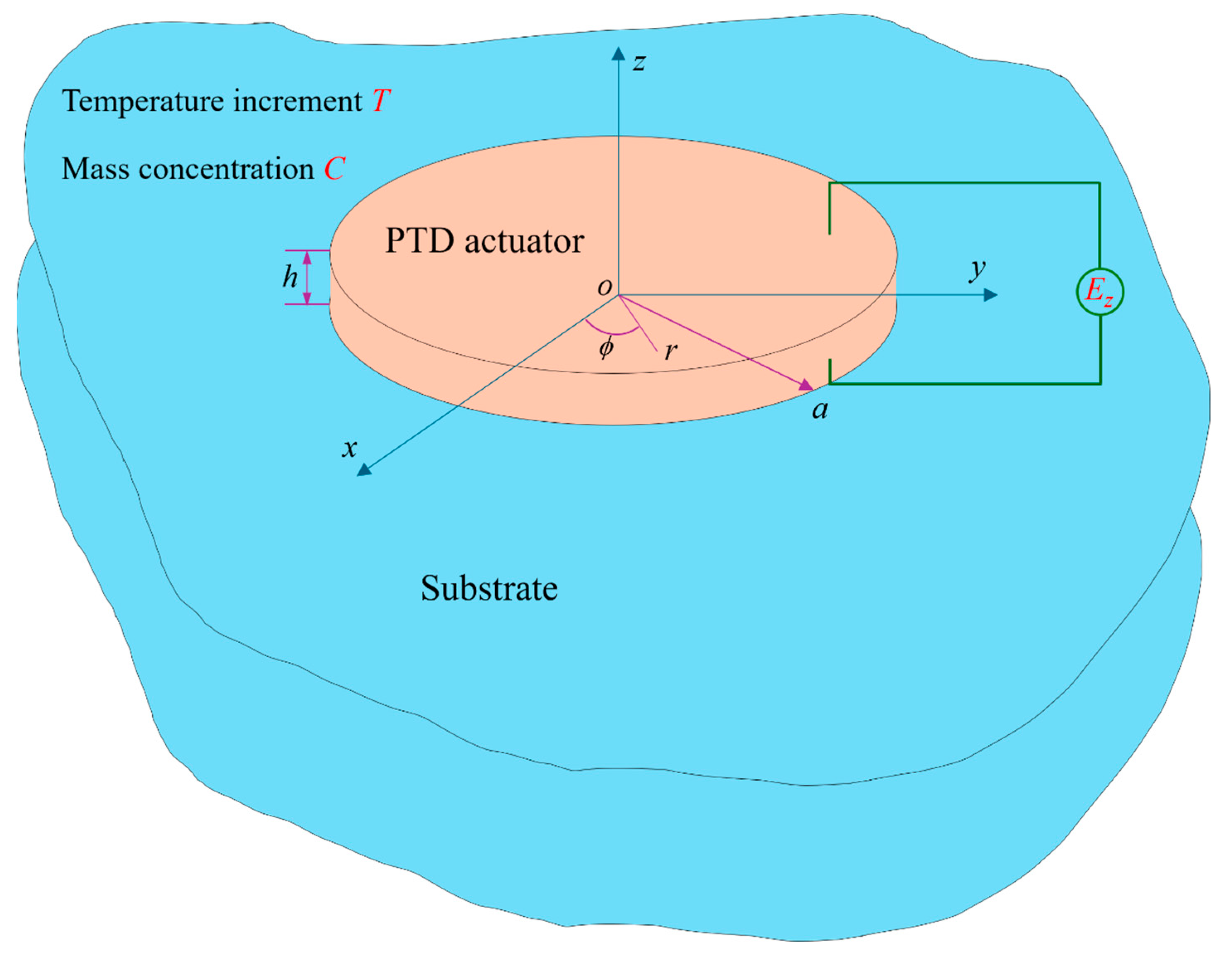
Figure 1. Schematics of a perfectly bonded model for an axisymmetric thin piezo-thermal-diffusive actuator under electrical-thermal-diffusive loads.
Modelling 06 00078 g001
Figure 2. Normalized SIF KII versus the truncation order N of Chebyshev polynomial for Cu substrate with a fixed aspect ratio h/a = 1/10.
Modelling 06 00078 g002
Figure 3. Distribution of interfacial shear stress for different aspect ratios with Cu substrate.
Modelling 06 00078 g003
Figure 4. Geometry and the finite element mesh used in the FEM simulation.
Modelling 06 00078 g004
Figure 5. Distribution of interfacial radial displacement for different aspect ratios.
Modelling 06 00078 g005
Figure 6. Distribution of radial stress of the PTD actuator for different aspect ratios.
Modelling 06 00078 g006
Figure 7. Distribution of hoop stress of the PTD actuator for different aspect ratios.
Modelling 06 00078 g007
Figure 8. Distribution of radial stress of substrate for different aspect ratios.
Modelling 06 00078 g008
Figure 9. Distribution of hoop stress of substrate for different aspect ratios.
Modelling 06 00078 g009
Figure 10. Distribution of interfacial shear stress for different substrate materials with fixed ratio h/a = 1/20.
Modelling 06 00078 g010
Figure 11. Distribution of interfacial radial displacement for different substrate materials with fixed ratio h/a = 1/20.
Modelling 06 00078 g011
Figure 12. Distribution of radial stress in PTD actuator for different substrate materials with fixed ratio h/a = 1/20.
Modelling 06 00078 g012
Figure 13. Distribution of hoop stress in PTD actuator for different substrate materials with fixed ratio h/a = 1/20.
Modelling 06 00078 g013
Figure 14. Distribution of radial stress in different substrate materials with fixed ratio h/a = 1/20.
Modelling 06 00078 g014
Figure 15. Distribution of hoop stress in different substrate materials with fixed ratio h/a = 1/20.
Modelling 06 00078 g015
Figure 16. SIFs for aspect ratio h/a in different substrate materials.
Modelling 06 00078 g016
Table 1. The material properties of three kinds of substrate materials.
MaterialE (GPa)va (10−6/K)
Cu1290.3517.0
ZrO22440.2910.6
Si1690.222.6
Disclaimer/Publisher’s Note: The statements, opinions and data contained in all publications are solely those of the individual author(s) and contributor(s) and not of MDPI and/or the editor(s). MDPI and/or the editor(s) disclaim responsibility for any injury to people or property resulting from any ideas, methods, instructions or products referred to in the content.