Article

Numerical Analysis of Composite Stiffened NiTiNOL-Steel Wire Ropes and Panels Undergoing Nonlinear Vibrations

by
Teguh Putranto
1,*,
Totok Yulianto
1,
Septia Hardy Sujiatanti
1,
Dony Setyawan
1,
Ahmad Fauzan Zakki
2,
Muhammad Zubair Muis Alie
3 and
Wibowo Wibowo
4
1
Department of Naval Architecture, Institut Teknologi Sepuluh Nopember, Surabaya 60111, Indonesia
2
Department of Naval Architecture, Universitas Diponegoro, Semarang 50275, Indonesia
3
Department of Ocean Engineering, Universitas Hasanuddin, Makassar 90245, Indonesia
4
Department of Mechanical Engineering, Universitas Sebelas Maret, Surakarta 57126, Indonesia
*
Author to whom correspondence should be addressed.
Modelling 2025, 6(3), 77; https://doi.org/10.3390/modelling6030077 (registering DOI)
Submission received: 21 May 2025 / Revised: 25 July 2025 / Accepted: 29 July 2025 / Published: 4 August 2025
(This article belongs to the Section Modelling in Engineering Structures)

Abstract

This research explores the application of NiTiNOL-steel (NiTi–ST) wire ropes as nonlinear damping devices for mitigating vibrations in composite stiffened panels. A dynamic model is formulated by coupling the composite panel with a modified Bouc–Wen hysteresis representation and employing the first-order shear deformation theory (FSDT), based on Hamilton’s principle. Using the Galerkin truncation method (GTM), the model is converted into a system of nonlinear ordinary differential equations. The dynamic response to axial harmonic excitations is analyzed, emphasizing the vibration reduction provided by the embedded NiTi–ST ropes. Finite element analysis (FEA) validates the model by comparing natural frequencies and force responses with and without ropes. A newly developed experimental apparatus demonstrates that NiTi–ST cables provide outstanding vibration damping while barely affecting the system’s inherent frequency. The N3a configuration of NiTi–ST ropes demonstrates optimal vibration reduction, influenced by excitation frequency, amplitude, length-to-width ratio, and composite layering.

1. Introduction

Composite stiffened panels are widely utilized in engineering because of their excellent strength-to-weight ratio and their flexibility to accommodate diverse shapes and design requirements [1,2,3]. However, these structures are often subject to vibrations caused by external factors, which can significantly affect their performance and structural integrity [4,5,6]. In recent years, significant attention has been given to developing techniques aimed at controlling and minimizing detrimental vibrations. Addressing the nonlinear vibration behavior of composite panels is crucial to ensure their long-term durability and stability, especially in environments such as aerospace and transportation, where dynamic loading conditions are common [7,8,9]. Effective vibration control strategies are essential to optimize the performance and lifespan of such composite structures [10,11].
Improving the performance of composite materials relies on optimizing their design and refining the associated manufacturing techniques [12], and carbon fiber composites are receiving significant attention due to their versatility [13]. Research showed that temperature significantly influenced the damping characteristics of composite structures, and advancements have been made in the development of novel fiber composites with superior reinforcement and impact resistance [14,15]. The experiments were integrated with damage algorithms to fully assess structural deterioration in composite materials [16]. Furthermore, numerous studies have aimed to improve the mechanical properties of composites, including detailed analyses of three-dimensional (3D) orthogonal woven composites, which investigate their unique structural characteristics and performance under various loading conditions [17]. Although well-designed composites can effectively reduce vibrations caused by external forces, challenges like high manufacturing costs, complexity, and performance trade-offs remain. Consequently, designing cost-efficient, reliable, and adaptable vibration control systems is crucial. Research on composite structures also extends to areas such as bending, buckling [18], stability [19,20], and free or forced vibrations [21]. Vibration control methods are generally categorized as active [22,23], passive [24,25], or semi-active [26,27]. Active and semi-active systems depend on external power sources, reliable control algorithms, and energy-harvesting solutions to maintain uninterrupted functionality [28,29]. In contrast, passive vibration control, which offers simple design, easy installation, and high reliability without external energy, provides a practical and efficient solution for vibration suppression in many applications.
Recent studies have shown increasing attention toward exploring the vibration isolation capabilities of shape memory alloys and wire rope configurations [30,31]. A key advancement in this field is a novel damper that integrates NiTiNOL with steel wire ropes. This damper exhibits impressive hysteresis nonlinear characteristics, essential for effective vibration suppression under various dynamic loads. Its performance has been validated through rigorous vibration tests, confirming its potential in practical applications. The development of a simplified dynamic model is essential to support further investigations. This approach facilitates a deeper understanding of the system’s behavior in different conditions. Advanced modeling techniques have been applied to identify the nonlinear properties of the NiTi–ST system [32,33]. These methods aim to reduce the complexity of mathematical models, making them more applicable in engineering contexts. Additionally, a novel nonlinear energy sink (NES) damping arrangement using NiTi–ST has been introduced. This arrangement aims to enhance vibration control capabilities. The integration of NiTi–ST with composite stiffened panels has enabled the effective modeling of hysteretic damping and nonlinear restoring forces through polynomial functions. Results show that this combination reduces transitional vibrations without altering the system’s natural frequency, maintaining structural integrity [34]. Collectively, these studies highlight NiTi–ST as a promising solution for nonlinear vibration suppression in engineering. However, a gap remains in applying NiTi–ST to composite structures, especially with methods involving multiple wire ropes. Addressing this gap could unlock new solutions for vibration-sensitive environments, particularly in aerospace and marine applications, where weight and efficiency are crucial.
In the maritime industry, vibrations in vessels can cause numerous problems, affecting structural integrity, crew comfort, and the functionality of onboard systems. The dynamic behavior of stiffened panels, commonly utilized in shipbuilding for their lightweight and strength properties, has been the subject of various studies focusing on vibration analysis and mitigation strategies. Research indicates that optimizing the design of these panels can significantly reduce resonance effects and enhance overall structural performance [35,36]. However, the specific application of NiTi–ST in composite stiffened panels for vibration reduction in marine environments remains largely unexplored. NiTi–ST is known for its unique characteristics, such as shape memory effects and superelasticity, which could offer innovative damping solutions. Although prior research has explored vibration control in composite materials and the application of shape memory alloys across different engineering fields, the incorporation of NiTi–ST into composite stiffened panels remains largely unexplored [37,38]. Investigating this innovative method could greatly improve the performance of composite stiffened panels by minimizing vibrations and boosting efficiency, highlighting the importance of continued research in this promising field [39,40].
The rest of this paper is organized as follows. Section 2 outlines the mechanical model of the system, describing the main components, their interactions, and the assumptions adopted to simplify the dynamic behavior, such as idealizations in geometry or boundary conditions. This section also presents the constitutive formulation, defining material behavior through stress-strain relationships, while accounting for elastic, plastic, and viscoelastic properties depending on the system’s material characteristics. Section 3 develops the mathematical framework for dynamic analysis by formulating the equations of motion, including mass, stiffness, and damping matrices, along with external forces and excitations, and derives the system’s response in both time and frequency domains. Section 4 provides practical examples to validate the model by comparing simulation results with experimental data and explores how the inclusion of wire ropes affects vibration damping. It also investigates the influence of large excitations, which may introduce nonlinearities, and evaluates the impact of key structural parameters, such as mass and stiffness, on vibration control and stability. Finally, Section 5 provides a summary of the main findings and contributions of the study, emphasizing the importance of the proposed model and suggesting possible avenues for future investigation.

2. Dynamic Equations

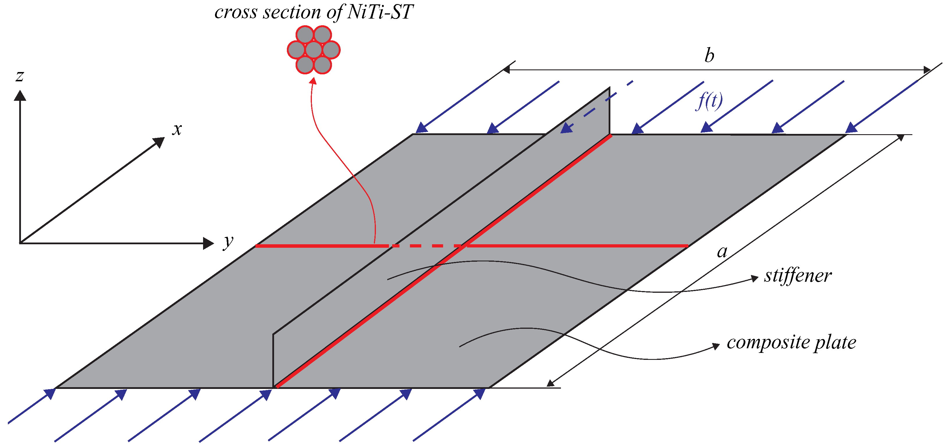
2.1. Mechanical Model

This study utilizes classical plate theory, where a NiTi–ST is integrated into the composite plate, as illustrated in Figure 1. The composite plate is positioned such that its central plane lies within a Cartesian coordinate system. The composite plate’s size is characterized by its length (a), width (b), and thickness (h). Two NiTi–ST components are embedded on the upper surface of the composite plate, with their placement described by horizontal ( x 1 , x 2 ) and vertical ( y 1 , y 2 ) coordinates. Additionally, the sides of stiffened composite panel where perpendicular to the stiffener direction are subjected to compression loading: f ( t ) = F 0 cos ω t , characterized by amplitude ( F 0 ), frequency ( ω ) and time (t).
In this section, the dynamics of composite stiffened panels are analyzed using Kirchhoff’s plate theory. The dynamic model, developed based on Figure 1, adheres to the following assumptions:
  • During deformation, the transverse normal to the composite plate’s mid-surface remains straight, and no strain occurs along the mid-surface.
  • The transverse normal remains unextended both prior to and following deformation, maintaining ε z = 0 .
  • Following deformation, the transverse normal undergoes rotation to maintain its perpendicular orientation to the composite plate’s mid-surface.
According to assumptions (1) and (2), the normal strain in the z-direction is zero ( ε z = 0 ). Furthermore, assumption (3) implies that the composite plate exhibits no transverse shear deformation under classical laminate theory, i.e., γ x z = γ y z = 0 .

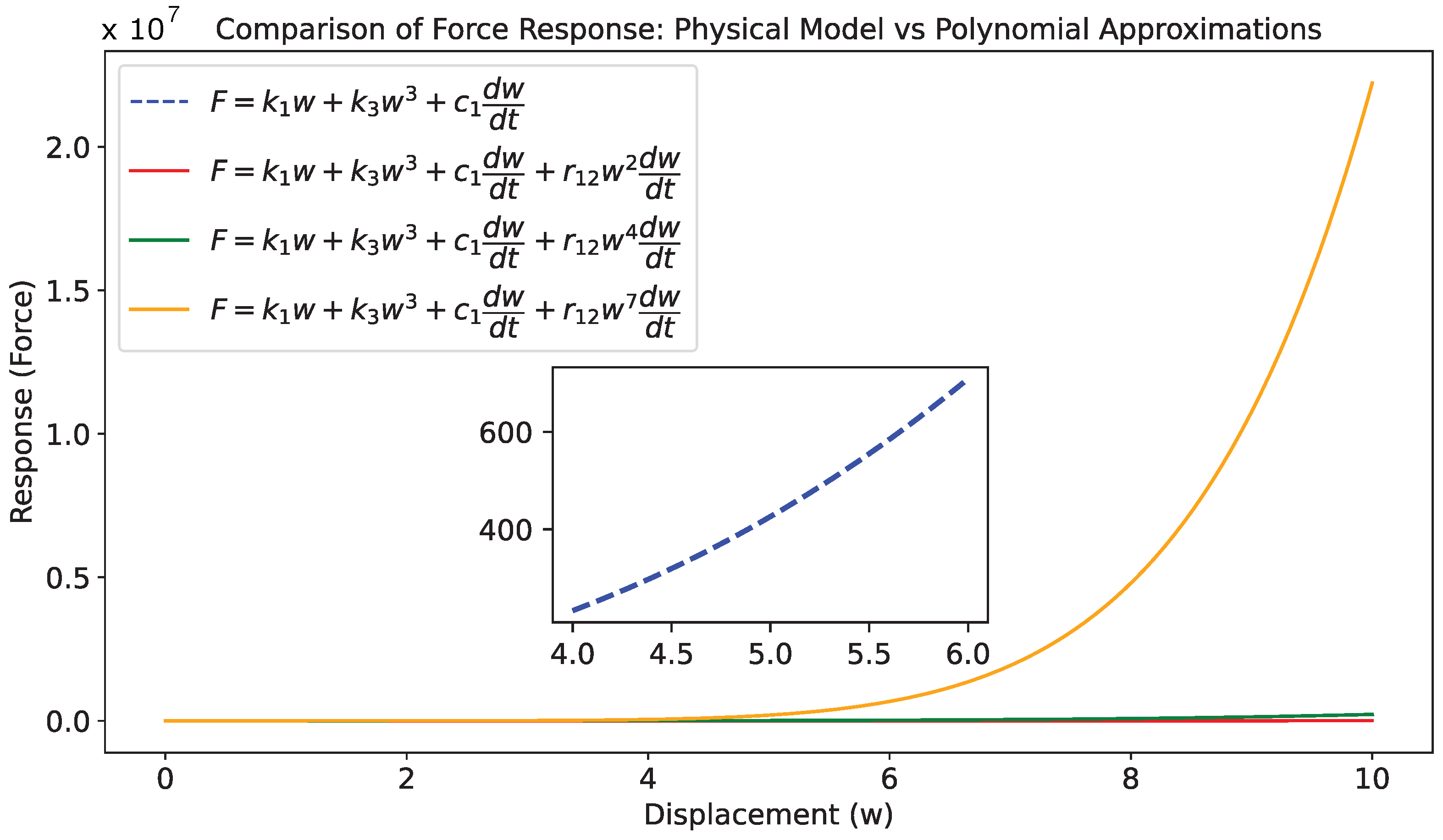
2.2. Constitutive Formulation

Given these assumptions, the displacement at any point within the composite plate can be described as follows [41]:
u ( x , y , z , t ) = z w x , v ( x , y , z , t ) = z w y , w ( x , y , t ) = w .
where u ( x , y , z , t ) , v ( x , y , z , t ) , and w ( x , y , t ) denote the displacement components in the directions of the x-axis, y-axis, and z-axis, respectively.
The composite plate’s normal and shear strain components can be described as follows:
ε x x = u x = z 2 w x 2 , ε y y = v y = z 2 w y 2 , γ x y = u y + v x = 2 z 2 w x y .
where ε x x and ε y y represent normal deformations along the x axis and the y axis, and γ x y denotes the shear deformation along the x -y plane.
Additionally, the zz-strain component has been introduced as:
ϵ z z = w z
The constitutive relation for the composite plate can be derived based on the generalized Hooke’s law, expressed as follows [42]:
σ x x σ y y τ x y σ z z = Q 11 Q 12 0 0 Q 21 Q 22 0 0 0 0 Q 66 0 0 0 0 Q 33 ϵ x x ϵ y y γ x y ϵ z z .
where σ x x , σ y y , σ z z represent the normal stresses in the x-axis, y-axis, and the transverse shear stress, respectively, while τ x y corresponds to the shear stress in the x y plane. Additionally, Q i j ( i , j = 1 , 2 , 3 , 6 ) denotes the components of the elastic stiffness matrix for the composite plate, given by:
Q 11 = E 1 1 μ 12 μ 21 , Q 22 = E 2 1 μ 12 μ 21 , Q 12 = μ 21 E 1 1 μ 12 μ 21 , Q 21 = μ 12 E 2 1 μ 12 μ 21 , Q 66 = G 12 , Q 33 = E 3 ( 1 ν 23 ν 32 ) .
where E 1 and E 2 are the Young’s moduli of a single-layer carbon fiber composite plate in the fiber direction and transverse to the fiber direction, respectively. Furthermore, μ 12 and μ 21 represent the associated Poisson’s ratios, while G 12 denotes the shear modulus.
Furthermore, the null zz-stress assumption has been replaced by the following expression, which accounts for σ z z as a function of the plate’s geometry and loading conditions:
σ z z = f ( z )
The Bouc–Wen model is a mathematical representation used to describe the nonlinear hysteretic behavior of systems, particularly those that exhibit damping characteristics under cyclic loading or vibrations. Key components of this model include restoring force coefficients such as k c (linear stiffness) and k 3 (cubic stiffness), which define how the system resists deformation. Additionally, damping coefficients like c 1 , r 12 , and r 21 control the energy dissipation of the system during motion. The parameters γ and β influence the rate of hysteresis and nonlinear damping behavior, respectively, while n determines the steepness of the hysteresis loop. A function h ( x ) is included to model the pinching effect near the origin, which is important for accurately capturing the stiffness variations of materials like NiTiNOL (used in vibration damping). These coefficients are typically identified experimentally, allowing the model to simulate energy dissipation, nonlinear stiffness, and dynamic response in systems such as vibration control devices, where the model helps predict the behavior of materials subjected to varying load conditions.
The nonlinear restoring force ( f s t ) provided by NiTi–ST, functioning as a damping device in the system, is expressed as follows [43]:
f s t = ( 1 r ) k c w 3 + r ( k e w + z h ) .
where f s t represents the transverse force along the z-axis, derived from the displacement field in the z-direction of the plate. The variable r serves as a weighting factor, whereas k c and k e correspond to the cubic elastic stiffness and linear stiffness coefficients, respectively.
The hysteresis damping force ( z h ) of the steel wire rope, modeled using the modified Bouc–Wen formulation, is governed by the following equation:
z h t = k d h x γ + β sgn z h w t z h n w t , h ( x ) = 1 ξ e w ( x ) 2 w c .
where k d , γ , β , n, ξ , w c are constitutive parameters, while h ( x ) denotes a function within the Bouc–Wen model, modified by a bell-shaped pinching function to control the tangent stiffness near the origin.
To facilitate the theoretical analysis of the modified Bouc–Wen model, the nonlinear term is limited to a maximum of third order. This simplification helps manage the complexity associated with the damping and restoring forces, which are described by differential equations distributed across the surface of the composite plate. Consequently, the resulting fitted restoring force function is given by:
f s t = k 1 w + k 3 w 3 + c 1 w t + r 21 w 2 w t r 12 w w t 2 .
where k 1 and k 3 represent the linear and nonlinear stiffness coefficients, respectively, while c 1 , r 12 , and r 21 correspond to the linear and nonlinear damping coefficients associated with the NiTi–ST.
The composite plate is composed of an epoxy resin polymer matrix reinforced with graphene nanosheets, as outlined in references [18,21]. To facilitate further theoretical analysis, the structural parameters incorporated into the dynamic model are also specified. In particular, Table 1 outlines the geometric dimensions and material properties of both the plate and the graphene nanosheets, whereas Table 2 lists the stiffness and damping characteristics of the NiTi–ST, derived through polynomial fitting.
In this study, the material behavior is modeled using elastic orthotropic anisotropy, which captures the directional stiffness properties of the material. However, plastic anisotropy is not considered in our model. We have assumed the hypothesis of isotropic plasticity, meaning that the material’s plastic behavior is treated as being the same in all directions, despite the elastic orthotropic anisotropy. This simplification is made because the study primarily focuses on the elastic response under dynamic loading conditions, and the material is not expected to undergo significant plastic deformation that would necessitate a more complex plastic anisotropy model.

3. Mathematical Analysis

3.1. Define the Dynamic Formulation

In this research, Hamilton’s principle is employed to derive the dynamic equations. The vibration response of the composite plate integrated with NiTi–ST is governed by the following differential equation:
δ t 2 t 1 T U d t + t 2 t 1 δ W f + δ W s t d t = 0 .
where T dan U represent the kinetic and potential energies of the composite plate, respectively. δ W f denotes the virtual work resulting from external excitation, while δ W s t accounts for the virtual work associated with the transverse restoring forces and damping effects provided by the NiTi–ST. The symbol δ signifies a variational operator.
The potential energy (U) of the composite plate is expressed as:
δ U = A h 2 h 2 σ x x δ ε x x + σ y y δ ε y y + τ x y δ γ x y + τ x z δ γ x z + τ y z δ γ y z d A d z = A N x x x δ u + 2 M x x x 2 δ w N y y y δ v + 2 M y y y 2 δ w N x y y δ v N x y x δ u + 2 2 M x y x y δ w d A ,
where variables of N i j and M i j can be expressed as follows:
N x x 2 w x 2 N y y 2 w x 2 N x y 2 w x 2 M x x 2 w x 2 M y y 2 w x 2 M x y 2 w x 2 = A 11 A 21 A 61 B 11 B 21 2 B 61 2 w x 2 A 12 A 22 A 62 B 12 B 22 2 B 62 2 w x 2 A 16 A 26 A 66 B 16 B 26 2 B 66 2 w x 2 B 11 B 21 B 61 D 11 D 21 2 D 61 2 w x 2 B 12 B 22 B 62 D 12 D 22 2 D 62 2 w x 2 B 16 B 26 B 66 D 16 D 26 2 D 66 2 w x 2 u x v y u y + v x 2 w x 2 2 w y 2 2 w x y   ,
where A, B, D matrices are symmetric, then ( A i j , B i j , D i j ) = ( A j i , B j i , D j i ). Furthermore, ( A i j , B i j , D i j ) matrices are written as follows:
A i j , B i j , D i j = k = 1 N z k 1 z k Q i j ¯ k 1 , z , z 2 d z , i , j = 1 , 2 , 6 ,
Superscript N is the number of composite layers. According to Hamilton’s principle, the kinetic energy (T) of the composite plate is defined as follows:
δ T = A h 2 h 2 ρ u t 2 + v t 2 + w t 2 d A d z = A [ I 0 u t δ u t + v t δ v t + w t δ w t + I 2 x w t x δ w t + y w t y δ w t ] d A ,
where the mass inertia coefficients ( I 0 and I 2 ) can be obtained from h 2 h 2 ρ d z and h 2 h 2 z 2 ρ d z , respectively.
The virtual work associated with the external harmonic excitation ( δ W f ) is represented by:
δ W f = f t c w t δ w ,
where the external force ( f t ) is written as F 0 cos ω t . Lastly, the external virtual work due to restoring force and damping can be written as:
δ W s t = f s t δ ^ x , y N , h 2 + f s t δ ^ x N , y , h 2 δ w ,
By substituting Equations (11)–(16) into Equation (10), the vibration differential equations for the composite plate incorporating NiTi–ST can be formulated as follows:
D 11 4 w x 4 + 4 D 16 4 w x 3 y + ( 2 D 12 + 4 D 66 ) 4 w x 2 y 2 + 4 D 26 4 w x y 3 + D 22 4 w y 4 + I 0 2 w t 2 I 2 4 w x 2 t 2 + 4 w y 2 t 2 + c a b w t F 0 a b cos ( ω t ) + χ a b f s t δ ^ x , y N , h 2 + f s t δ ^ x N , y , h 2 = 0 ,
where
f s t = k 1 w + k 3 w 3 + c 1 w t + r 21 w 2 w t r 12 w w t 2 .
Equations (17) and (18) describe the displacement w ( x , y , t ) of a system, such as a plate or membrane, under dynamic loading conditions. The material properties are represented by coefficients D 11 , D 16 , D 12 , D 66 , D 26 , D 22 , which relate to bending stiffness and directional couplings. I 0 and I 2 are inertia-related parameters, with I 0 representing mass and I 2 affecting damping. c is a damping coefficient, and a b denotes system dimensions. The force amplitude F 0 and angular frequency ω describe a time-varying force, while χ and f s t are factors influencing boundary conditions. The delta function δ ^ models localized forces or conditions at specific points. The variables x , y , t , x N , y N , h represent spatial coordinates, time, and system thickness, respectively, describing the system’s behavior and response.
Figure 2 compares the force response of a system modeled by the physical equation and various polynomial approximations of different orders. The physical model, represented by a blue dashed line, includes linear stiffness, cubic nonlinearity, and a damping term, while the third-order polynomial approximation (red line) introduces a quadratic damping term for a more complex response. Higher-order polynomial approximations (green and orange lines) further refine the model by adding additional damping terms, with the 5th and 7th orders introducing increasingly sophisticated nonlinearity. As the polynomial order increases, the response becomes smoother, especially at higher displacements, demonstrating the effect of higher-order damping terms on the system’s behavior. This analysis highlights the growing complexity and accuracy of the model as higher-order terms are included.
The equation below is derived in accordance with the boundary conditions that govern the composite plate system:
w = 0 , 2 w x 2 = 0 , ( x = 0 , x = a ) w = 0 , 2 w y 2 = 0 , ( y = 0 , y = b ) N x y = 0 , N y = 0 , M y = 0 , ( y = 0 , b ) .
The vibration differential equation is converted into a dimensionless form to simplify subsequent theoretical analysis and calculations. The dimensionless version of the equation is expressed as follows:
D 11 ¯ 4 w x 4 + 4 D 16 ¯ 4 w x 3 y + ( 2 D 12 ¯ + 4 D 66 ¯ ) 4 w x 2 y 2 + 4 D 26 ¯ 4 w x y 3 + D 22 ¯ 4 w y 4 + I 0 ¯ 2 w t 2 I 2 ¯ 1 α 2 4 w x 2 t 2 + 1 β 2 4 w y 2 t 2 + c ¯ w t cos ( w ¯ t ) + k 1 ¯ w + k 3 ¯ w 3 + c 1 ¯ w t + r ¯ 21 w 2 w t r ¯ 12 w w t 2 δ ^ x ¯ , y ¯ N , h 2 + k 1 ¯ w + k 3 ¯ w 3 + c 1 ¯ w t + r ¯ 21 w 2 w t r ¯ 12 w w t 2 δ ^ x ¯ N , y ¯ , h 2 = 0 ,
where
x ¯ = x a , y ¯ = y b , w ¯ = w h , α = a h , β = b h , I 0 ¯ = h 3 D 11 a 2 b 3 F 0 , I 2 ¯ = h D 11 I 2 a 2 b 3 F 0 I 0 , D 11 ¯ = b h a 3 F 0 , D 16 ¯ = h D 16 a 2 F 0 , D 12 ¯ = h D 12 a b F 0 , D 66 ¯ = h D 66 a b F 0 , D 26 ¯ = h D 26 b 2 F 0 , D 22 ¯ = a h b 3 F 0 , c ¯ = c h 2 a b F 0 D 11 a b I 0 , ω ¯ = a b c D 11 , t ¯ = t h a b D 11 a b I 0 , k 1 ¯ = χ h k 1 F 0 , k 3 ¯ = χ h 3 k 3 F 0 , c 1 ¯ = χ c h 2 a b F 0 D 11 a b I 0 , r 21 ¯ = χ r 21 h 4 a b F 0 D 11 a b I 0 , r 12 ¯ = χ r 12 h 4 D 11 a 3 b 3 F 0 I 0 .
where c is a coefficient, possibly related to damping or another material property. The variable c ¯ is a dimensionless parameter obtained by normalizing the coefficient c with respect to system dimensions, the applied force, and the thickness of the system.

3.2. Deriving the Dynamic Response

The dimensionless displacement function that meets these boundary conditions is given by:
ω ¯ x ¯ , y ¯ , t ¯ = m × n = 1 M × N ω ¯ m × n = m = 1 M n = 1 N X m Y n q i t ¯ , X m = cosh λ m x ¯ cos λ m x ¯ α m sinh λ m x ¯ sin λ m x ¯ , Y n = 1 , n = 1 3 1 2 y ¯ , n = 2 cosh μ n y ¯ + cos μ n y ¯ β n sinh μ n y ¯ + sin μ n y ¯ , n = 3 cosh λ m x ¯ cos λ m x ¯ = 1 , cosh μ n y ¯ cos μ n y ¯ = 1 , α m = cosh λ m cos λ m sinh λ m sin λ m , β n = cosh μ n cos μ n sinh μ n sin μ n .
The equation represents the normalized angular frequency ω ¯ ( x ¯ , y ¯ , t ¯ ) as a function of normalized spatial coordinates x ¯ and y ¯ , and time t ¯ . The terms X m and Y n describe spatial dependencies in the x- and y-directions, with specific forms for different values of n. X m involves hyperbolic and trigonometric functions of λ m , while Y n varies based on n, including constants and hyperbolic functions. The time-dependent term q i ( t ¯ ) modulates the frequency. The parameters λ m and μ n are spatial frequencies for the x- and y-directions, respectively, and α m and β n are scaling coefficients based on the spatial dependencies. The terms M and N correspond to the truncation orders used in the Galerkin truncation method (GTM), with M × N defining the overall order of the GTM applied to the composite stiffened panels.
This study employs Galerkin truncation methods of various orders of the 2nd-order ( M = 1 , N = 2 ), 4th-order ( M = 2 , N = 2 ), 6th-order (either M = 2 , N = 3 or M = 3 , N = 2 ), 8th-order ( M = 4 , N = 2 ), and 9th-order ( M = 3 , N = 3 ) to analyze and compare the vibration responses of composite stiffened panels, aiming to validate the accuracy of the approach.
Owing to the inclusion of squared and cubic terms, the harmonic expressions for displacement, velocity, and acceleration of the plate equipped with NiTi–ST can be formulated as follows:
q i t ¯ = a i 0 + j = 1 J a i j cos j ω ¯ t ¯ + j = 1 J b i j sin j ω ¯ t ¯ q ˙ i t ¯ = j = 1 J j ω ¯ b i j cos j ω ¯ t ¯ j = 1 J j ω ¯ a i j sin j ω ¯ t ¯ q ¨ i t ¯ = j = 1 J j 2 ω ¯ 2 b i j sin j ω ¯ t ¯ j = 1 J j 2 ω ¯ 2 a i j cos j ω ¯ t ¯
where ˙ and ¨ denote the first and second time derivatives of the generalized coordinate vector, respectively. The variable J indicates the order of the harmonic balance. The term a i 0 is a constant, while a i j and b i j are the coefficients corresponding to the cosine and sine components, respectively.
Figure 3 presents a comparison between the analytical solution obtained via the harmonic balance method and the numerical solution derived using the Runge–Kutta (RK) method. The RK method is employed to compute the time-domain response of the composite stiffened panel’s amplitude under external harmonic excitation at a given frequency. Additionally, frequency-amplitude characteristic curves generated by the harmonic balance method (HBM) are examined. The findings demonstrate strong agreement between both approaches, providing further confirmation of the accuracy of the proposed method. These methods are solved using the Python 3.10 (Python Software Foundation, Wilmington, DE, USA) and Ansys 2023 R1 (Ansys Inc., Canonsburg, PA, USA) softwares.
Furthermore, significant error differences (50% to 100%) observed between the HBM and RK methods arise primarily due to the inherent differences in how each method handles the system, as shown in Figure 3. The HBM, being a frequency-domain method, works effectively for steady-state periodic systems but struggles with capturing transient behaviors, especially in strongly nonlinear systems. In contrast, the RK method, a time-domain approach, can model both transient and steady-state responses, but its accuracy is sensitive to the chosen step size and initial conditions, which can lead to discretization errors when the step size is not appropriately selected.
The frequency is determined by solving the nonlinear system of differential equations resulting from the vibration model, see in Equation (24). The generalized frequencies are related to the natural frequencies of the system as:
ω n = k m
where k is the stiffness and m is the mass associated with the system. These frequencies correspond to the resonant frequencies at which the system vibrates when subjected to external harmonic excitation.
The displacement w ( x , y , t ) describes the deformation or movement of the composite stiffened panel over time and space, see in Equation (25). In the given model, the displacement is expressed as a function of spatial coordinates x and y, as well as time t. The displacement equation for the system incorporates both the generalized coordinates and mode shapes. The generalized displacement function is written as:
w ( x , y , t ) = m = 1 M n = 1 N X m Y n q i ( t )
where q i ( t ) is the generalized coordinate vector, representing the time-dependent displacement of the system. The variables of X m and Y n are the spatial mode shapes in the x- and y-directions, respectively.
A three-dimensional graph was generated to illustrate the amplitude distribution of composite stiffened panels under different conditions. Figure 4a displays the amplitude response of the 3D composite stiffened panels without the inclusion of the NiTi–ST device, whereas Figure 4b shows the response when a 50% vibration-damping effect is applied. Theoretical analysis confirms that the proposed model accurately captures the system’s dynamic behavior, confirming its reliability. The results demonstrate that the NiTi–ST device effectively reduces vibrations in composite stiffened panels by dissipating energy, thereby improving structural stability. Additionally, optimizing the stacking sequence and positioning of the NiTi–ST layers can lead to enhanced vibration control. This performance can be further validated through finite element simulations and numerical analyses utilizing the Runge–Kutta method. Moving forward, experimental studies will be carried out under practical conditions to assess the real-world effectiveness of the NiTi–ST device in vibration mitigation for composite stiffened panels.

4. Examples

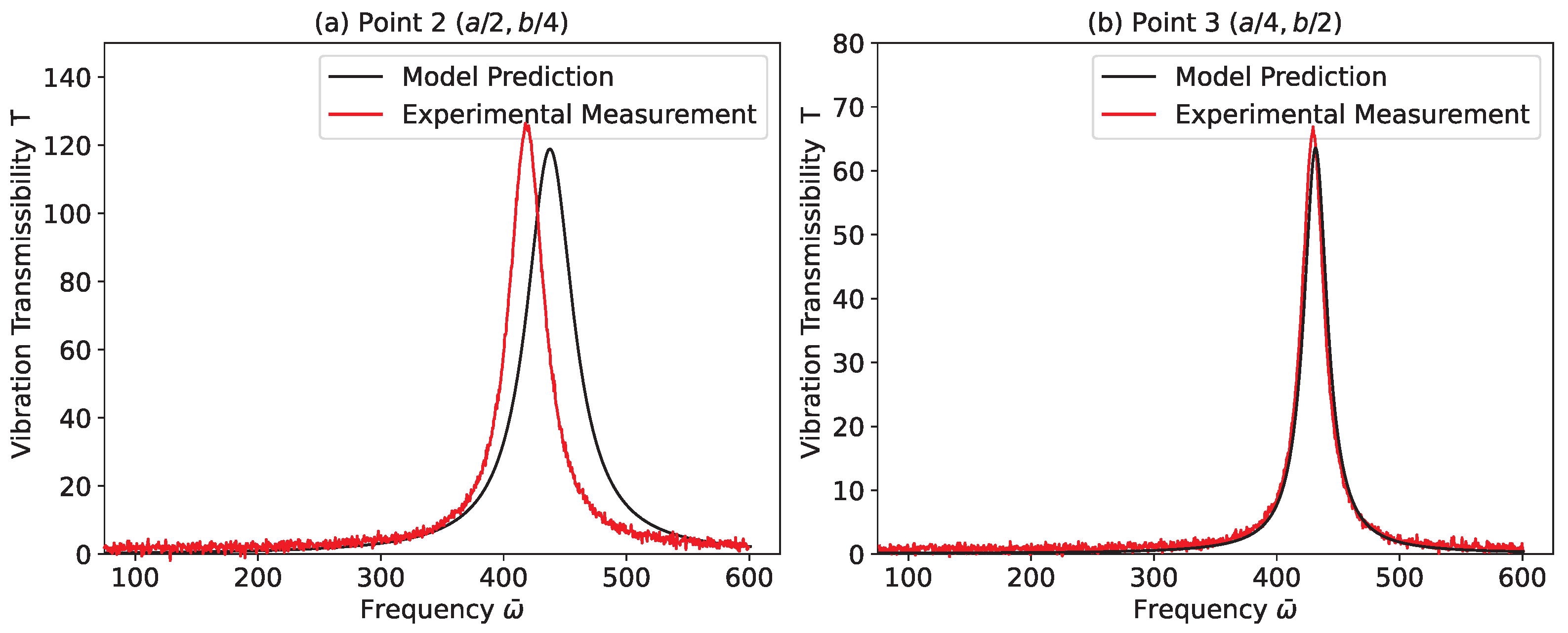
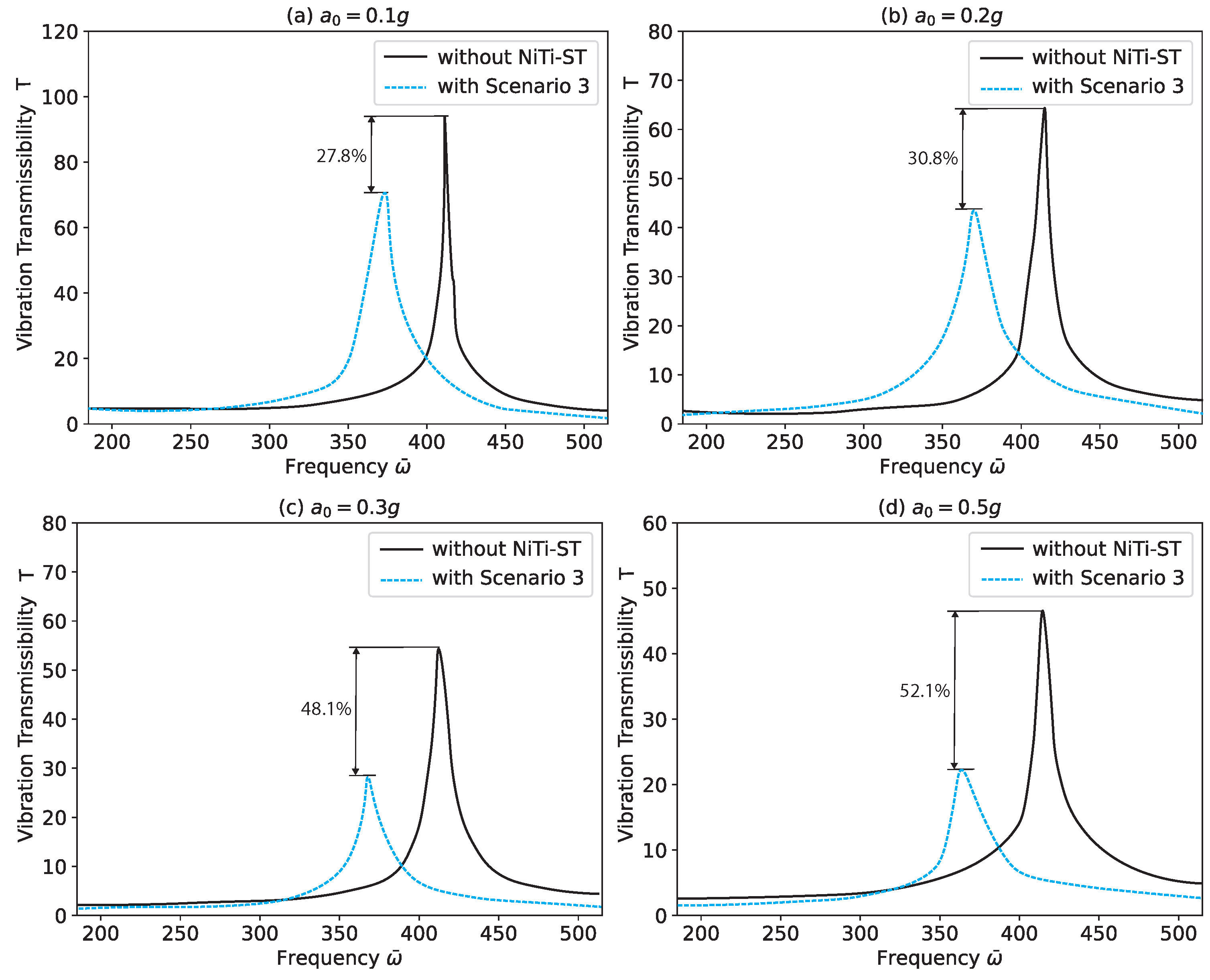
4.1. Vibration Effect Due to NiTi–ST Configurations

The theoretical amplitude response is converted into a vibration transmissibility format and compared with experimental data, as depicted in Figure 5. The comparison reveals a close match between the theoretical predictions and experimental findings, demonstrating a strong correlation between the simulations and observed behavior. This further confirms the soundness of the experimental setup and the dependability of its execution.
Vibration transmissibility, denoted as T, quantifies the ratio of the amplitude of the output response to the amplitude of the input excitation. It is expressed as:
T = A output A input
where T is the vibration transmissibility, A output is the amplitude of the output response, A input is the amplitude of the input excitation.
This ratio helps to assess the effectiveness of vibration isolation systems and is often plotted against frequency to characterize the system’s damping or vibration isolation performance.
Figure 6 presents the response characteristics during excitation for composite stiffened panels with and without the incorporation of NiTi–ST. In Table 3, the study introduces four distinct NiTi–ST embedding configurations: Scenario 1 involves embedding three NiTi–ST elements along the lengthwise direction; Scenario 2 increases this to six NiTi–ST elements in the same direction. Scenario 3 uses a total of six NiTi–ST elements, three along the length and three along the width. Finally, Scenario 4 incorporates 12 NiTi–ST elements, evenly distributed with six in the lengthwise and six in the widthwise directions. Each rope-embossed scenario clearly enhances the damping performance of the composite stiffened panels. Consistent with the theoretical predictions, Scenario 4 demonstrates the most effective vibration reduction. The damping efficiencies measured for Scenarios 1 to 4 are 22.2%, 11.1%, 33.5%, and 15.7%, respectively. Moreover, the presence of NiTi–ST has a minimal impact on the natural frequency of the system. From both the perspective of frequency shift and vibration control, the numerical simulation findings align well with the theoretical analysis.
To further evaluate the vibration control performance of NiTi–ST under varying conditions, vibration transmissibility results are taken at four different points on the composite stiffened panels. Figure 7 displays the amplitude vibration transmissibility at the midpoint (Point 1 at a / 2 , b / 2 ) under different excitation levels. Results for Point 2 ( a / 2 , b / 4 ) are shown in Figure 8. In both cases, Scenario 3 consistently delivers the best vibration suppression performance.
Figure 9 and Figure 10 further support these findings, showing the vibration transmissibility at point 3 ( a / 4 , b / 2 ) and point 4 ( a / 4 , b / 4 ), respectively. These comparisons between the reference condition (without NiTi–ST) and Scenario 3 reveal that the damping performance remains effective at various locations on the composite stiffened panels. Although the magnitude of external excitation affects the vibration transmissibility, NiTi–ST consistently reduces vibration regardless of position or excitation level. It is also observed that Scenario 3 exhibits nonlinear vibration control characteristics when subjected to high excitation levels.
In summary, a comprehensive set of experiments confirms the effectiveness of the different embedding scenarios in reducing vibrations. Figure 11 compiles the vibration transmissibility data at all measured points at multiple excitation levels, where the red, blue, green, and orange points represent Scenarios 1 to 4, respectively. Table 4 lists the vibration reduction effectiveness of 50 mm NiTi–ST segments for each scenario at different locations in the composite stiffened panels.

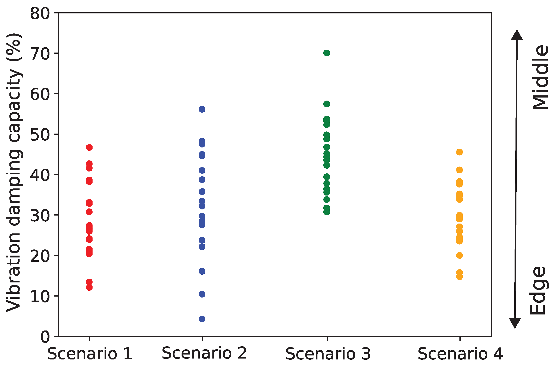
4.2. Effect of Wire Ropes on Vibration Damping

Figure 12 illustrates the vibration-damping performance of four wire rope isolator configurations, as detailed in Table 5. Among these, the N1a setup shows the most effective vibration suppression, highlighting its strong damping capacity. Meanwhile, N2b presents a mild softening behavior, where system stiffness decreases as displacement increases. Interestingly, N1a not only performs well in damping but also exhibits signs of slight hardening, indicating increased stiffness at larger displacements, which may enhance dynamic stability under certain loading conditions.
When the excitation level increases to 0.22, as depicted in Figure 13b, the four configurations display more prominent softening responses. This behavior is typical of nonlinear systems and can be attributed to the internal mechanisms of the wire rope, such as friction between the strands, wire deformation, and asymmetric stiffness under compression and tension. These nonlinear restoring forces become more significant at larger amplitudes, affecting the stiffness of the system and altering the frequency response.
Figure 14 further explores how structural responses evolve with increasing excitation. The blue solid line represents stable responses, while the red dotted line indicates unstable branches predicted by linearized stability theory [45]. The N1a system shows a transition from hardening to softening—its resonance curve first bends to the right, then shifts leftward. In contrast, the other configurations (N1b, N2a, and N2b) consistently show softening behavior, with resonance curves shifting left as excitation increases. Notably, N1a also exhibits subharmonic vibrations, where the system responds at fractional frequencies of the input, signaling complex nonlinear dynamics. At higher excitations, all configurations undergo a noticeable amplitude jump, a signature of multistability and sudden shifts between response states in nonlinear systems.

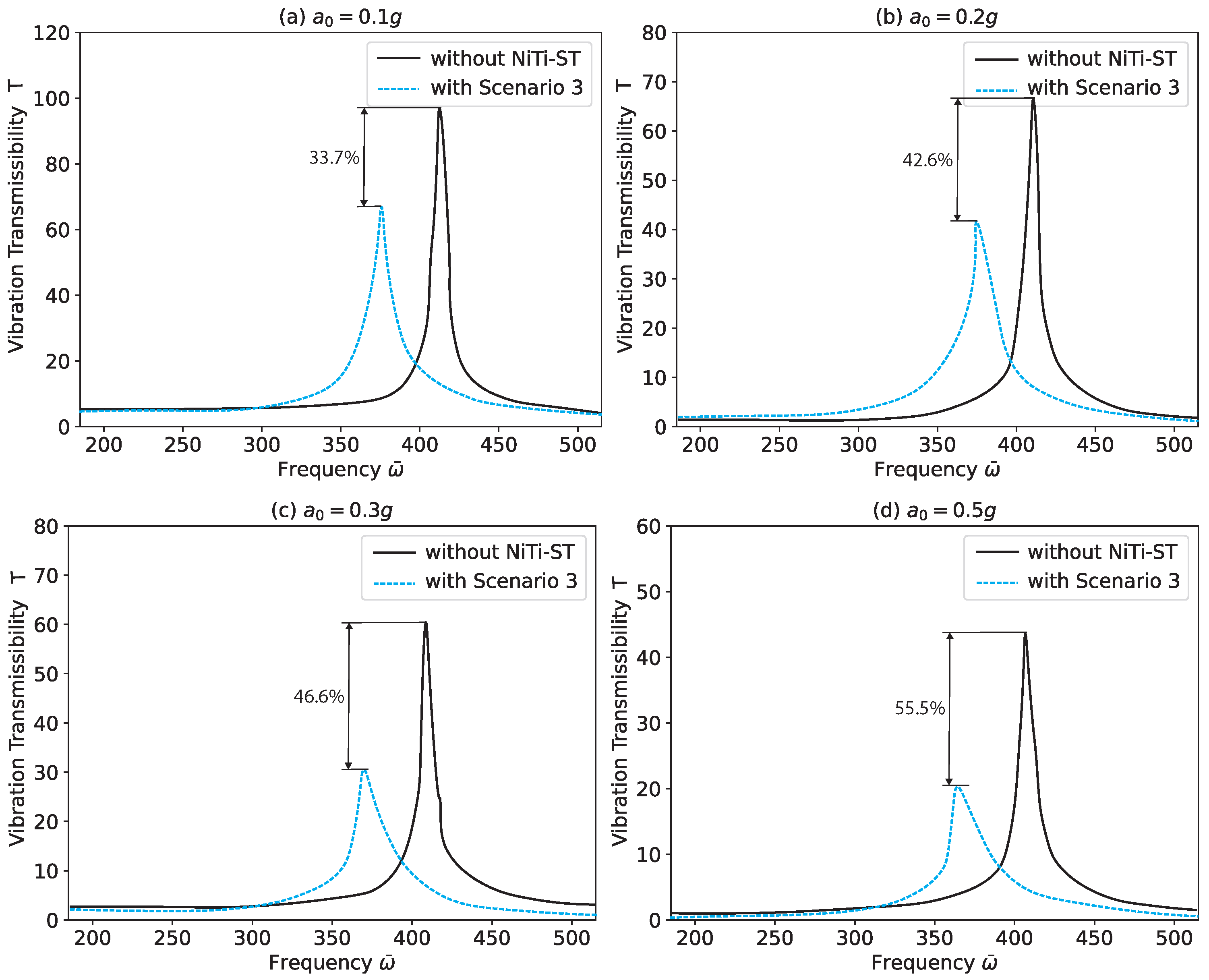
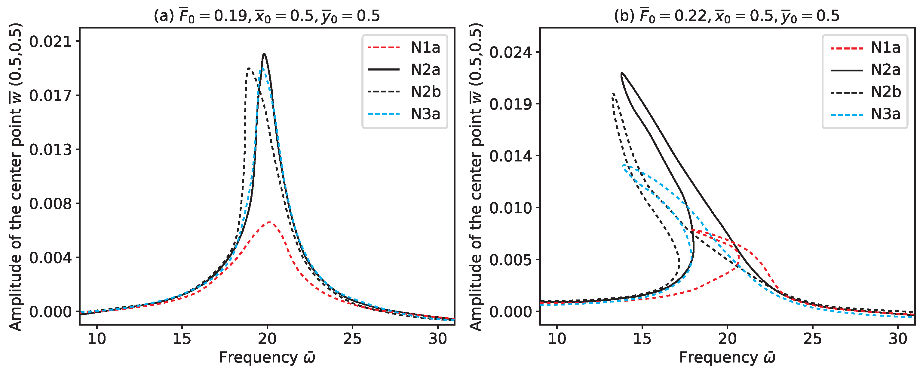
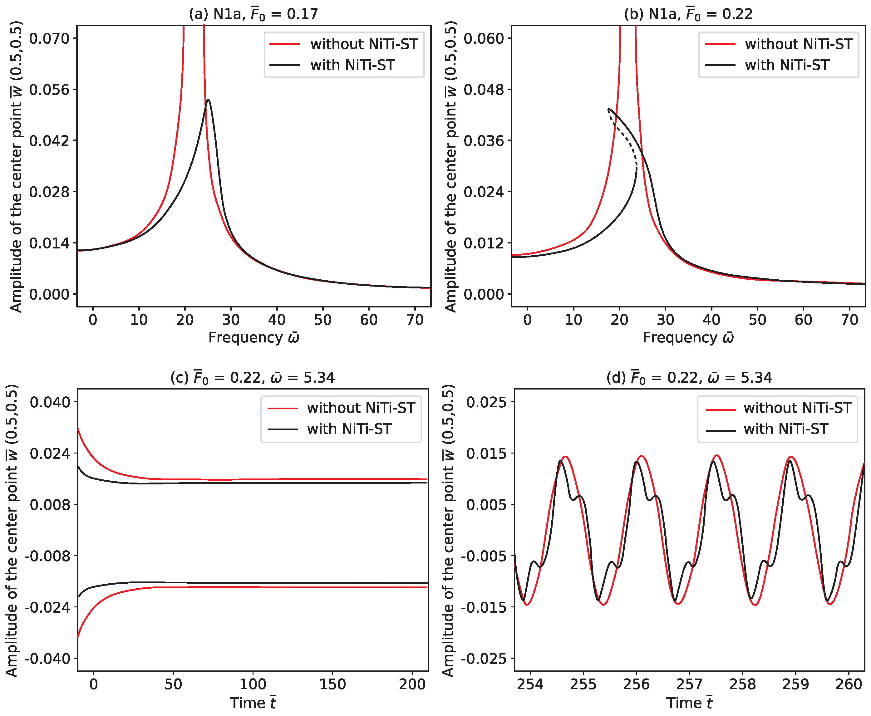
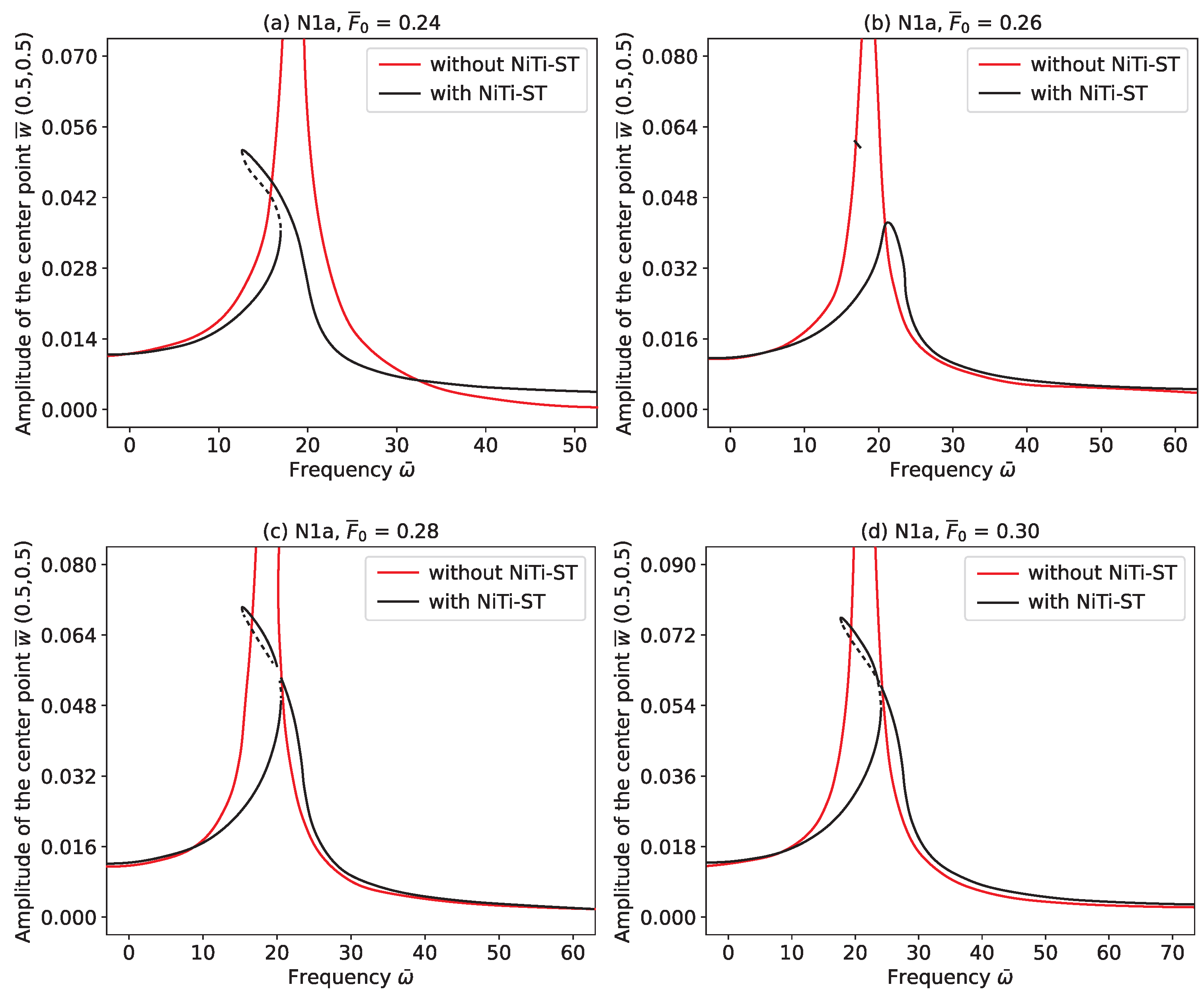
4.3. Effect of Large Excitation on Vibration Response

Figure 15 illustrates the progression of the complex dynamic characteristics of the NiTi–ST-integrated system as the dimensionless external excitation level, F ¯ 0 , varies. At lower excitation levels, depicted in Figure 15a, the system exhibits a stable primary response curve, indicative of predominantly linear dynamic behavior. As F ¯ 0 increases, nonlinear effects become increasingly evident. Notably, an isolated, closed-loop resonance branch forms near the resonant frequency, as shown in Figure 15b,c. This loop represents a hallmark of nonlinear dynamics, expanding in size and gradually approaching the primary response curve as excitation grows. Consequently, the frequency range associated with large-amplitude vibrations broadens.
At higher excitation levels, such as in Figure 15d, the closed-loop resonance branch eventually merges with the primary response curve. This convergence marks the onset of a strongly nonlinear regime characterized by amplitude jumps and multi-valued solutions, signaling a critical transition in the system’s behavior. Despite the increasing complexity introduced by these nonlinearities, the NiTi–ST system retains effective damping capabilities, which continue to suppress excessive vibration amplitudes and maintain overall system stability.

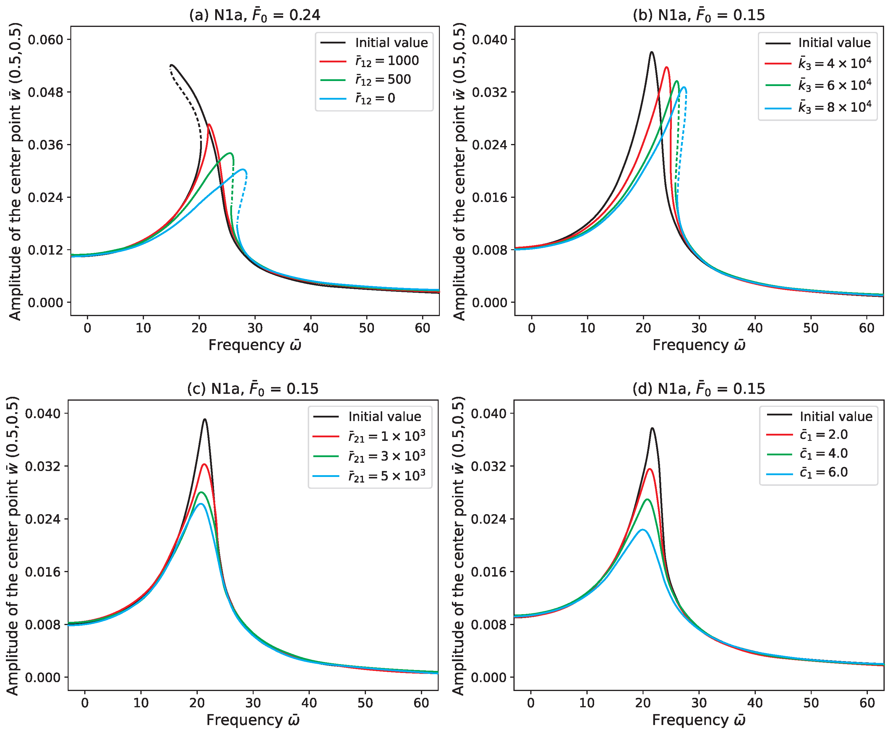
4.4. Effect of Structural Parameter on Vibration Control

This section explores how variations in key structural parameters influence the vibration suppression performance of the NiTi–ST-integrated system. The baseline values for the nonlinear damping coefficient r ¯ 12 , cross-coupling damping r ¯ 21 , cubic stiffness k ¯ 3 , and equivalent linear damping c ¯ 1 are initialized at 4.34 × 10 3 , 2.86 × 10 4 , 1.42 × 10 6 and 2.00 , respectively. As illustrated in Figure 16a, reducing the nonlinear damping parameter r ¯ 12 causes the disappearance of the amplitude jump phenomenon, transitioning the system’s behavior from a softening to a hardening type. This shift highlights the sensitivity of the structural response to nonlinear damping, which not only alters the amplitude–frequency relationship but also significantly affects the overall system dynamics. Specifically, r ¯ 12 governs the degree of nonlinearity and determines whether the system will exhibit abrupt changes in amplitude near resonance, which can complicate control strategies and necessitate careful tuning of damping properties.
Furthermore, the influence of cubic stiffness k ¯ 3 is examined in Figure 16b. An increase in k ¯ 3 results in the rightward shift of the response curve, indicating a higher resonant frequency and a modest reduction in amplitude. This behavior is consistent with the hardening nature of the system, especially for configurations such as Sa1 that exhibit the highest cubic stiffness. The observed rightward shift suggests that stronger cubic stiffness leads to increased structural rigidity, which elevates the system’s resistance to deformation under dynamic loading. Additionally, Figure 16c,d reveal the effects of varying r ¯ 21 and c ¯ 1 , where enhancements in either parameter strengthen the damping effect without altering the resonance frequency. Among these, the linear damping coefficient c ¯ 1 plays a pivotal role in dissipating vibrational energy. While higher-order damping terms in the polynomial model capture nonlinear hysteresis effects, the majority of energy dissipation originates from the linear damping mechanism, confirming its dominant contribution in reducing vibrational amplitudes.
In addition to parameter variation, the spatial position of the NiTi–ST layer also influences damping efficiency, as shown in Figure 17. The study evaluates the effect of different laying positions of the N1a configuration on the vibrational response of the system. Optimal suppression is observed when the damping layer is positioned along the central axis of the plate, specifically at x ¯ 0 = 0.5 and y ¯ 0 = 0.5 . This central placement maximizes the interaction between the damping element and the plate’s dominant vibrational modes, thereby enhancing energy dissipation. Conversely, as the placement moves away from the center, the effectiveness of vibration control diminishes due to decreased interaction with high-deformation regions. These findings suggest that not only the material properties but also the spatial deployment of damping elements must be strategically considered in practical applications to achieve the desired vibration suppression.

5. Conclusions

This study developed a dynamic theoretical model of carbon fiber composite stiffened panels embedded with NiTi-based shape memory alloy wire ropes (NiTi–ST) to explore their vibration control effectiveness. The vibration equations were derived through Hamilton’s principle, nondimensionalized, and discretized via the GTM. The resulting algebraic equations were then solved using the HBM, with amplitude–frequency responses obtained through root mean square (RMS) analysis. Model validation was conducted through multiple approaches, including the RK method, finite element modal analysis, and nonlinear hysteresis modeling based on a modified Bouc–Wen model. Experimental composite stiffened panels embedded with NiTi–ST were also fabricated to confirm the theoretical findings. The results indicated that NiTi–ST significantly reduces vibrations without substantially affecting the system’s natural frequencies. Additionally, the damping effectiveness was strongly influenced by the layup configuration, with the N1a setup yielding the best performance. Under harmonic excitation, the model effectively suppressed multiple mode resonances and allowed for analysis of nonlinear dynamic phenomena such as softening, hardening, and coexistence of dynamic responses (CDR) through linearized stability theory.
The conclusions highlight that NiTi alloys, as shape memory materials, offer great potential as nonlinear damping elements for advanced vibration control. The damping characteristics, particularly at the central region of the composite stiffened panels, were more pronounced compared to the edges, suggesting location-sensitive performance. The transformation between soft and hard nonlinear dynamic behaviors can be tuned through nonlinear damping adjustments, while linear damping remains a dominant factor in achieving overall vibration suppression. However, excessive excitation that triggers the CDR phenomenon may negatively affect the damping effect, indicating the importance of optimizing the external input. This research not only confirms the effectiveness of embedding NiTi–ST in composite structures but also emphasizes that merely increasing the number of embedded ropes does not necessarily improve performance. Instead, optimized embedding strategies, such as the N1a layout, yield superior results. This integrated theoretical and experimental investigation provides valuable insights for the practical application of shape memory alloy damping systems in high-performance fields such as aerospace and aviation, while also pointing toward future challenges in balancing mass constraints with damping efficiency.

Author Contributions

Conceptualization, T.P.; methodology, T.P., A.F.Z., M.Z.M.A. and W.W.; software, T.P.; validation, T.P., T.Y., D.S. and S.H.S.; formal analysis, T.P. and D.S.; investigation, T.P., T.Y. and S.H.S.; resources, T.P.; data curation, T.P.; writing—original draft preparation, T.P.; writing—review and editing, T.P.; visualization, T.P.; supervision, T.P.; project administration, T.P.; funding acquisition, T.P. All authors have read and agreed to the published version of the manuscript.

Funding

This research was funded by Ministry of Education, Culture, Research, and Technology of Indonesia, number 038/E5/PG.02.00.PL/2024.

Data Availability Statement

Data are contained within this article.

Conflicts of Interest

The authors declare no conflicts of interest.

References

  1. Zhang, Y.W.; Zhang, H.; Hou, S.; Xu, K.F.; Chen, L.Q. Vibration suppression of composite laminated plate with nonlinear energy sink. Acta Astronaut. 2016, 123, 109–115. [Google Scholar] [CrossRef]
  2. Rajak, D.K.; Pagar, D.D.; Kumar, R.; Pruncu, C.I. Recent progress of reinforcement materials: A comprehensive overview of composite materials. J. Mater. Res. Technol. 2019, 8, 6354–6374. [Google Scholar] [CrossRef]
  3. Prabowo, A.R.; Sohn, J.M.; Putranto, T. Crashworthiness performance of stiffened bottom tank structure subjected to impact loading conditions: Ship-rock interaction. Curved Layer. Struct. 2019, 6, 245–258. [Google Scholar] [CrossRef]
  4. Wang, S.; Rolland, Y.; Soares, C.G. Analytical and numerical analysis of slamming induced vibrations on composite plates. Ocean Eng. 2022, 258, 111643. [Google Scholar] [CrossRef]
  5. Peças, P.; Carvalho, H.; Salman, H.; Leite, M. Natural fibre composites and their applications: A review. J. Compos. Sci. 2018, 2, 66. [Google Scholar] [CrossRef]
  6. Putranto, T.; Kõrgesaar, M.; Tabri, K. Application of Equivalent Single Layer Approach for Ultimate Strength Analyses of Ship Hull Girder. J. Mar. Sci. Eng. 2022, 10, 1530. [Google Scholar] [CrossRef]
  7. Zheng, H.; Zhang, W.; Li, B.; Zhu, J.; Wang, C.; Song, G.; Wu, G.; Yang, X.; Huang, Y.; Ma, L. Recent advances of interphases in carbon fiber-reinforced polymer composites: A review. Compos. Part B Eng. 2022, 233, 109639. [Google Scholar] [CrossRef]
  8. Putranto, T. Equivalent single layer approach for ultimate strength analysis of box girder under bending load. Ocean Eng. 2024, 292, 116535. [Google Scholar] [CrossRef]
  9. Diatmaja, H.; Prabowo, A.R.; Muhayat, N.; Tuswan, T.; Putranto, T. Fast ship prototype design simulation with fin stabilizer on hydrodynamic characteristics for ship realization planning. IOP Conf. Ser. Earth Environ. Sci. 2023, 1166, 012048. [Google Scholar] [CrossRef]
  10. Ibrahim, R.A. Recent advances in nonlinear passive vibration isolators. J. Sound Vib. 2008, 314, 371–452. [Google Scholar] [CrossRef]
  11. Wu, M.Q.; Zhang, W.; Chronopoulos, D. Nonlinear vibrations and dynamic snap-through behaviors of four-corner simply supported bistable asymmetric laminated composite square shell. Mech. Syst. Signal Process. 2022, 173, 109023. [Google Scholar] [CrossRef]
  12. Ghadge, R.; Ghorpade, R.; Joshi, S. Multi-disciplinary design optimization of composite structures: A review. Compos. Struct. 2022, 280, 114875. [Google Scholar] [CrossRef]
  13. Jung, D.; Yu, W.-R.; Ahn, H.; Na, W. New b-value parameter for quantitatively monitoring the structural health of carbon fiber-reinforced composites. Mech. Syst. Signal Process. 2022, 165, 108328. [Google Scholar] [CrossRef]
  14. Chandra, S.; Maeder, M.; Bienert, J.; Beinersdorf, H.; Jiang, W.; Matsagar, V.A.; Marburg, S. Identification of temperature-dependent elastic and damping parameters of carbon–epoxy composite plates based on experimental modal data. Mech. Syst. Signal Process. 2023, 187, 109945. [Google Scholar] [CrossRef]
  15. Wu, M.; Jia, L.; Chen, Z.; Wang, J.; Yan, R. Synergetic enhancement of interfacial properties and impact resistant of UHMWPE fiber reinforced composites by oxygen plasma modification. Compos. Struct. 2022, 292, 115663. [Google Scholar] [CrossRef]
  16. Zeng, X.; Zhao, B.; Liu, X.; Yu, Y.; Guo, J.; Qing, X. Lamb wave-based damage assessment for CFRP composite structures using a CHMM-based damage localization algorithm and a damage quantitative expression. Mech. Syst. Signal Process. 2023, 184, 109750. [Google Scholar] [CrossRef]
  17. Yang, X.; Ai, J.; Zhu, H.; Du, X.-B.; Li, D.-S.; Jiang, L.; Fang, D.-N. Multi-directional compression behaviors and failure mechanisms of 3D orthogonal woven composites: Parametric modeling and strength prediction. Mater. Des. 2022, 222, 111108. [Google Scholar] [CrossRef]
  18. Song, M.; Yang, J.; Kitipornchai, S. Bending and buckling analyses of functionally graded polymer composite plates reinforced with graphene nanoplatelets. Compos. Part B Eng. 2018, 134, 106–113. [Google Scholar] [CrossRef]
  19. Sayed, M.; Mousa, A.A.; Mustafa, I.H. Stability analysis of a composite laminated piezoelectric plate subjected to combined excitations. Nonlinear Dyn. 2016, 86, 1359–1379. [Google Scholar] [CrossRef]
  20. Mousa, A.A.; Sayed, M.; Eldesoky, I.M.; Zhang, W. Nonlinear stability analysis of a composite laminated piezoelectric rectangular plate with multi-parametric and external excitations. Int. J. Dyn. Control. 2014, 2, 494–508. [Google Scholar] [CrossRef]
  21. Song, M.; Kitipornchai, S.; Yang, J. Free and forced vibrations of functionally graded polymer composite plates reinforced with graphene nanoplatelets. Compos. Struct. 2017, 159, 579–588. [Google Scholar] [CrossRef]
  22. Lu, J.; Wang, P.; Zhan, Z. Active vibration control of thin-plate structures with partial SCLD treatment. Mech. Syst. Signal Process. 2017, 84, 531–550. [Google Scholar] [CrossRef]
  23. Sun, Y.; Song, Z.; Li, F. Theoretical and experimental studies of an effective active vibration control method based on the deflection shape theory and optimal algorithm. Mech. Syst. Signal Process. 2022, 170, 108650. [Google Scholar] [CrossRef]
  24. Chen, H.Y.; Mao, X.Y.; Ding, H.; Chen, L.Q. Elimination of multimode resonances of composite plate by inertial nonlinear energy sinks. Mech. Syst. Signal Process. 2020, 135, 106383. [Google Scholar] [CrossRef]
  25. Fang, Z.W.; Zhang, Y.W.; Li, X.; Ding, H.; Chen, L.Q. Integration of a nonlinear energy sink and a giant magnetostrictive energy harvester. J. Sound Vib. 2017, 391, 35–49. [Google Scholar] [CrossRef]
  26. Hu, W.; Gao, Y.; Yang, B. Semi-active vibration control of two flexible plates using an innovative joint mechanism. Mech. Syst. Signal Process. 2019, 130, 565–584. [Google Scholar] [CrossRef]
  27. Zhao, J.; Gao, Z.; Li, H.; Wong, P.K.; Xie, Z. Semi-active control for the nonlinear vibration suppression of square-celled sandwich plate with multi-zone MRE filler core. Mech. Syst. Signal Process. 2022, 172, 108953. [Google Scholar] [CrossRef]
  28. Yang, T.; Zhang, Y.Q.; Zhou, S.X. Multistage oscillators for ultra-low frequency vibration isolation and energy harvesting. Sci. China Technol. Sci. 2022, 65, 631–645. [Google Scholar] [CrossRef]
  29. Ma, X.; Zhou, S. A review of flow-induced vibration energy harvesters. Energy Convers. Manag. 2022, 254, 115223. [Google Scholar] [CrossRef]
  30. Carboni, B.; Lacarbonara, W.; Brewick, P.T.; Masri, S.F. Dynamical response identification of a class of nonlinear hysteretic systems. J. Intell. Mater. Syst. Struct. 2018, 29, 2795–2810. [Google Scholar] [CrossRef]
  31. Carboni, B.; Lacarbonara, W.; Auricchio, F. Hysteresis of multiconfiguration assemblies of nitinol and steel strands: Experiments and phenomenological identification. J. Eng. Mech. 2015, 141, 04014135. [Google Scholar] [CrossRef]
  32. Brewick, P.T.; Masri, S.F.; Carboni, B.; Lacarbonara, W. Data-based nonlinear identification and constitutive modeling of hysteresis in NiTiNOL and steel strands. J. Eng. Mech. 2016, 142, 04016107. [Google Scholar] [CrossRef]
  33. Brewick, P.T.; Masri, S.F.; Carboni, B.; Lacarbonara, W. Enabling reduced-order data-driven nonlinear identification and modeling through naïve elastic net regularization. Int. J. Non-Linear Mech. 2017, 94, 46–58. [Google Scholar] [CrossRef]
  34. Zhang, Y.; Xu, K.; Zang, J.; Ni, Z.; Zhu, Y.; Chen, L. Dynamic design of a nonlinear energy sink with NiTiNOL-steel wire ropes based on nonlinear output frequency response functions. Appl. Math. Mech. 2019, 40, 1791–1804. [Google Scholar] [CrossRef]
  35. Liu, Z.; Niu, J.; Jia, R. Dynamic analysis of arbitrarily restrained stiffened plate under moving loads. Int. J. Mech. Sci. 2021, 200, 106414. [Google Scholar] [CrossRef]
  36. Mouritz, A.P.; Gellert, E.; Burchill, P.; Challis, K. Review of advanced composite structures for naval ships and submarines. Compos. Struct. 2001, 53, 21–42. [Google Scholar] [CrossRef]
  37. Prusty, B.G. Free vibration and buckling response of hat-stiffened composite panels under general loading. Int. J. Mech. Sci. 2008, 50, 1326–1333. [Google Scholar] [CrossRef]
  38. Shao, C.; Huang, Y. Advances in Shape Memory Alloy-Based Reinforcement in Steel Structures: A Review. Buildings 2023, 13, 2760. [Google Scholar] [CrossRef]
  39. Li, X.; Jin, G.; Deng, M. Nonlinear Vibration Control Experimental System Design of a Flexible Arm Using Interactive Actuations from Shape Memory Alloy. Sensors 2023, 23, 1133. [Google Scholar] [CrossRef]
  40. Tabrizikahou, A.; Kuczma, M.; Łasecka-Plura, M.; Farsangi, E.N.; Noori, M.; Gardoni, P.; Li, S. Application and modelling of Shape-Memory Alloys for structural vibration control: State-of-the-art review. Constr. Build. Mater. 2022, 342, 127975. [Google Scholar] [CrossRef]
  41. Zang, J.; Liu, P.P.; Zhang, Y.W.; Chen, L.Q. The performance of nonlinear vibration control via NiTiNOL–Steel wire ropes. Commun. Nonlinear Sci. Numer. Simul. 2023, 118, 107058. [Google Scholar] [CrossRef]
  42. Xue, J.R.; Zhang, Y.W.; Niu, M.Q.; Chen, L.Q. Vibration reduction in a composite laminated cylindrical shell via embedded NiTiNOL-steel wire ropes. Nonlinear Dyn. 2023, 111, 7181–7197. [Google Scholar] [CrossRef]
  43. Carboni, B.; Lacarbonara, W. Nonlinear dynamic characterization of a new hysteretic device: Experiments and computations. Nonlinear Dyn. 2016, 83, 23–39. [Google Scholar] [CrossRef]
  44. Zheng, L.H.; Zhang, Y.W.; Ding, H.; Chen, L.Q. Nonlinear vibration suppression of composite laminated beam embedded with NiTiNOL-steel wire ropes. Nonlinear Dyn. 2021, 103, 2391–2407. [Google Scholar] [CrossRef]
  45. Zang, J.; Zhang, Y.W. Responses and bifurcations of a structure with a lever-type nonlinear energy sink. Nonlinear Dyn. 2019, 98, 889–906. [Google Scholar] [CrossRef]
Figure 1. Stiffened composite plate with NiTi–ST.
Modelling 06 00077 g001
Figure 2. Comparison of the force response for different models.
Modelling 06 00077 g002
Figure 3. Comparison between harmonic balance method (HBM) and RK Method.
Modelling 06 00077 g003
Figure 4. Amplitude of composite stiffened panels at different positions.
Modelling 06 00077 g004
Figure 5. Comparison of model prediction with experimental measurement obtained from [18].
Modelling 06 00077 g005
Figure 6. Response characteristics during excitation of a 0 = 0.5 g, Point 1 ( a / 2 , b / 2 ).
Modelling 06 00077 g006
Figure 7. Vibration transmissibility of numerical results at Point 1 ( a / 2 , b / 2 ).
Modelling 06 00077 g007
Figure 8. Vibration transmissibility of numerical results at Point 2 ( a / 2 , b / 4 ).
Modelling 06 00077 g008
Figure 9. Vibration transmissibility of numerical results at Point 3 ( a / 4 , b / 2 ).
Modelling 06 00077 g009
Figure 10. Vibration transmissibility of numerical results at Point 4 ( a / 4 , b / 4 ).
Modelling 06 00077 g010
Figure 11. Comparison of damping capacity of different scenarios.
Modelling 06 00077 g011
Figure 12. Behavior of plates incorporating various NiTi–ST configurations under low and high excitation levels.
Modelling 06 00077 g012
Figure 13. Subharmonic resonant response at low harmonic frequencies.
Modelling 06 00077 g013
Figure 14. Nonlinear and unstable behavior of the structure as F ¯ 0 increases from 0.19 to 0.22.
Modelling 06 00077 g014
Figure 15. Influence of distinct external excitations on complex dynamic characteristics.
Modelling 06 00077 g015
Figure 16. Influence of structural parameters on vibration control.
Modelling 06 00077 g016
Figure 17. Amplitude of the NiTi–ST different laying positions under F ¯ 0 = 0.17 .
Modelling 06 00077 g017
Table 1. Geometric and material properties of composite plate and graphene nanosheets [24].
ItemNotationValueUnit
Length of composite platea600mm
Width of composite plateb600mm
Thickness of composite plate t p 8mm
Web height of stiffener h w 150mm
Flange width of stiffener b f 50mm
Total layerk10-
Density ρ 1760kg/ m 3
Young’s modulus in the x-direction E 1 110.3GPa
Young’s modulus in the y-direction E 2 6.5GPa
Poisson’s ratio μ 12 0.23-
Stiffness modulus G 12 12GPa
Table 2. Stiffness and damping parameters of NiTi–ST [44].
Item k 1 (N/m) k 3 (N/m3) c 1 (Ns/m) r 12 (Ns/m3) r 21 (Ns2/m3)
N1a- 4.16 × 10 8 118.2 1.699 × 10 6 5.249 × 10 4
N2a5966-52.1 1.259 × 10 5 9876
N2b4523-16.5 1.077 × 10 5 2608
N3a6016 3.23 × 10 7 50.0 3.396 × 10 5 2.261 × 10 4
Table 3. Description of Vibration Control Scenarios with NiTi–ST Wire Ropes.
ScenarioDescriptionNiTi–ST ConfigurationNumber of NiTi–ST ElementsPlacementDamping Performance
Scenario 1Basic configuration with three NiTi–ST elements along the lengthwise direction.NiTi–ST in lengthwise direction3Placed along the panel length22.2% damping efficiency
Scenario 2Increased damping with six NiTi–ST elements in the lengthwise direction.NiTi–ST in lengthwise direction6Placed along the panel length11.1% damping efficiency
Scenario 3Optimized configuration with six NiTi–ST elements, three along the length and three along the width.NiTi–ST in length and width directions6Three along the length and three along the width33.5% damping efficiency
Scenario 4Maximized vibration reduction with 12 NiTi–ST elements, six in both lengthwise and widthwise directions.NiTi–ST in length and width directions12Evenly distributed, six in length and six in width15.7% damping efficiency
Table 4. Mean vibration-damping performance of NiTi–ST over a 50 mm length on composite stiffened panels.
Average Efficiency (%)Point 1Point 2Point 3Point 4
Scenario 11.764.175.251.42
Scenario 22.294.884.901.58
Scenario 32.004.065.891.50
Scenario 41.825.295.691.77
Table 5. Parameters of different NiTi–ST configurations with restoring force and damping force fitting.
Item k 1 (N/m) k 3 (N/ m 3 ) c 1 (N·s/m) r 21 (N·s/m3) r 12 (N ·s 2 / m 3 )R-Square
N1a 4.23 × 10 8 120.40 1.696 × 10 6 5.274 × 10 4 0.9817
N2a616655.09 1.289 × 10 5 99860.9966
N2b462318.49 1.217 × 10 5 28280.9943
N3a6316 3.258 × 10 7 52.96 3.456 × 10 5 2.36 × 10 4 0.9986
Disclaimer/Publisher’s Note: The statements, opinions and data contained in all publications are solely those of the individual author(s) and contributor(s) and not of MDPI and/or the editor(s). MDPI and/or the editor(s) disclaim responsibility for any injury to people or property resulting from any ideas, methods, instructions or products referred to in the content.

