1. Introduction
In conventional vector control systems designed for permanent magnet synchronous motors (PMSMs), speed and position sensors typically play an essential role. In the vast majority of industrial settings, mechanical sensors such as photoelectric encoders or resolvers are employed to precisely detect the motor’s speed and pole position. Nevertheless, practical applications have revealed several drawbacks. The installation and replacement procedures of these sensors are often cumbersome, and the associated maintenance and utilization costs are considerably high. Such issues pose significant challenges in fulfilling the demands for simplicity, cost-effectiveness, and reliability in speed control systems, ultimately leading to a substantial increase in overall system costs. Research on sensorless control strategies for PMSM has consequently garnered substantial attention from scholars both domestically and abroad [
1,
2,
3].
Common PMSM sensorless control strategies include the following: (1) The application of the model reference adaptive method [
4,
5] strictly depends on the establishment of an accurate reference model. In case of an inaccurate reference model, the speed observation will be severely distorted. This distortion directly undermines the system’s speed identification and deteriorates the control effect of the speed control system; (2) the extended Kalman filter (EKF) [
6,
7] demonstrates effective noise suppression and high estimation accuracy in nonlinear systems. However, its performance significantly degrades under motor parameter variations due to inherent linearization errors. The computational complexity arising from Jacobian matrix calculations and covariance propagation further limits its real-time applicability in high-dimensional systems. These characteristics constrain EKF’s practical deployment in scenarios requiring rapid parameter adaptation or strict timing constraints; (3) the flux observer-based speed estimation method [
8,
9] exhibits inherent limitations due to the absence of dedicated error compensation mechanisms, rendering it particularly susceptible to motor parameter variations (e.g., rotor resistance drift or inductance changes). This deficiency leads to significant estimation errors under dynamic operating conditions, thereby compromising system robustness and resulting in inferior anti-interference capabilities when subjected to parameter uncertainties or external disturbances. The lack of adaptive compensation for flux estimation discrepancies further exacerbates performance degradation in high-precision applications requiring rapid parameter adaptation; (4) neural network-based observers face key real-time applicability challenges due to their inherent architectural limitations [
10,
11]. Specifically, the multi-layered network structure necessitates intricate forward propagation calculations, wherein the cumulative computation of weight matrix multiplications and activation function operations grows exponentially with the number of neurons and hidden layers. Moreover, gradient-based update mechanisms, which are essential for model adaptation, require iterative backpropagation processes (including the computation of error gradients across all network layers and the adjustment of numerous parameters) to minimize estimation errors. These combined factors introduce prohibitive computational delays that frequently exceed the millisecond-scale latency requirements critical for time-sensitive applications such as high-speed motor control or real-time robotics, where even microsecond-level delays can lead to system instability or performance degradation.
In the field of PMSM modeling, the inherent nonlinearity of its mathematical framework necessitates that the stability of observer design be prioritized as a fundamental challenge [
12,
13]. Owing to the combined effects of motor parameter variations, load fluctuations, external disturbances, and measurement noise sensitivity, the system’s speed and position estimation algorithms must exhibit a requisite level of adaptivity to maintain robustness across diverse operating conditions. The Lyapunov-based adaptive observer design not only rigorously guarantees global asymptotic convergence of observation errors theoretically but also dynamically tracks motor parameter variations (e.g., stator resistance and flux amplitude) in real time to suppress parameter drift while effectively compensating for load torque fluctuations and measurement noise, thereby significantly enhancing robust estimation accuracy across diverse operating conditions [
14,
15]. Through rigorous theoretical analysis and comprehensive system simulations, the results of this study demonstrate that the proposed Multi-dimensional Taylor Network (MTN) can serve as a viable alternative to conventional neural networks, offering superior capabilities in dynamic system modeling and control [
16,
17,
18]. Fundamentally, the MTN is inherently a polynomial-type nonlinear auto-regressive moving average model, composed of a multitude of linear and nonlinear terms that can extend to infinity, thus enabling it to robustly represent state dynamics in a general sense, particularly for unstable systems, and provides an explicit description of system behavior. Specifically, the MTN surpasses traditional approaches by enabling more precise and resilient representations of complex nonlinear dynamics. Additionally, its simple structure and fast computing speed render it feasible for real-time control. Notably, the PID controller is a special case of the MTN controller, with its parameters serving as viable initial values for the latter, thereby enhancing the overall performance of observer-based estimation and control schemes for PMSM systems.
To conclude, in this study, we address the state estimation challenge in PMSM systems by integrating the excellent approximation capability and adaptive characteristics of the MTN. A nonlinear observer design approach for MTN-based PMSM systems is proposed, which systematically leverages the MTN’s dynamic adaptive mechanisms to develop online adaptive learning rules suitable for complex nonlinear systems, thereby forming an observer architecture that balances approximation accuracy and robustness. Theoretically, through the construction of Lyapunov functions and rigorous mathematical derivation, the global asymptotic stability of the proposed observer in closed-loop systems and its effective state estimation capability for PMSM systems are proven. Compared with the NN-based design in [
19], our MTN uses a single-layer polynomial structure to approximate nonlinearities, reducing computational time by about 40% while maintaining position error below 0.02 rad. Unlike the chattering-prone sliding mode observer in [
20], our scheme integrates Lyapunov stability theory into MTN weight adaptation, eliminating speed fluctuations and ensuring smooth torque output. Compared with the EKF method in [
21], our observer tolerates up to 10-fold stator resistance variations, with position error increasing by only 0.05 rad-demonstrating superior robustness. Additionally, we design an inverse control framework with the MTN observer, forming a closed-loop system that further improves dynamic response. The findings demonstrate that this design framework, which merges intelligent network theory with control theory, provides a novel technical pathway to address model uncertainties and parameter time-variation issues in nonlinear system observer design.
The subsequent organization of this paper is arranged as follows:
Section 2 establishes the PMSM state space model by transforming the motor’s mathematical model, laying a rigorous mathematical foundation for observer design.
Section 3 focuses on the design of the MTN observer, detailing the MTN model structure, its approximation principle for nonlinear systems, and the specific formulation of the observer, while comparing its computational complexity with traditional multi-layer perceptual neural networks (MLPNN) through a table.
Section 4 conducts stability analysis of the MTN observer using Lyapunov stability theory, deriving the adaptive learning rule for MTN weights and proving the uniform ultimate boundedness of estimation errors.
Section 5 designs the MTN-observer-based inverse control scheme, introducing the “special structure” composed of three MTNs (model identifier, adaptive inverse controller, and adaptive nonlinear observer) and explaining the key steps of online/offline training.
Section 6 verifies the effectiveness of the proposed scheme through simulation experiments, analyzing speed response performance, estimation errors under preset and parameter-varied conditions, and quantifying the observer’s robustness and real-time performance. Finally,
Section 7 summarizes the main findings of the study, highlights the advantages of the MTN-based nonlinear observer, and supplements future research directions.
2. PMSM State Space Model
In this section, we present the transformation of the PMSM mathematical model from the coordinate system to the coordinate system for observer design. This conversion is achieved through a systematic coordinate transformation framework, which decouples the stator current components and enhances the observability of the system states. By leveraging the orthogonal properties of the coordinate system, the dynamic equations are recast into a canonical form suitable for advanced estimation techniques. The mathematical derivation involves constructing a transformation matrix that maps the original -frame variables to the -frame domain, ensuring the preservation of electromagnetic torque and flux linkages during the coordinate transformation. This methodological approach not only simplifies the observer design process but also provides a rigorous foundation for analyzing the stability and performance of the closed-loop control system.
The relationship between the
coordinate system and the
coordinate system is shown in Equation (1), where
and
are the
,
axis stator currents, respectively, and
is the rotor position.
The dynamic model of the PMSM in the
coordinate system can be expressed by Equation (2), where
and
are the
,
shaft stator voltages, respectively.
The derivation of the PMSM state equations follows the classic modeling method for surface-mounted PMSMs, where the cross-coupling terms and the influence of rotor permanent magnet flux are considered [
22].
To facilitate a clearer understanding of the notations used in the PMSM mathematical model, especially those in Equations (1) and (2), the key notations are summarized in
Table 1.
Set
,
,
as Equations (3)–(5), respectively, and perform coordinate transformation to express the system in state-space form, thereby obtaining Equation (6), where
,
are the known constant matrices, which is observable with respect to
; the system inputs
,
and outputs
can be measured directly.
Using
to represent each variable, if
is observable, the velocity
and the position angle
can be expressed by Equation (7). Therefore, the measurement of
and
can be transferred to the observation of
.
3. MTN Observer Design
The MTN model is suitable for modeling general nonlinear systems with unknown mechanisms, as shown in
Figure 1. Based on the multiple-input-multiple-output MTN model, the dynamical equations of the
n-dimensional nonlinear system can be described as shown in Equation (8), where
represents a nonlinear function described by the MTN model, with the basic concept of approximating a complex function by a simple one;
is the
p-th weight before each item;
is the total number of expansions; and
is the power of
in the
p-th product term.
As shown in
Figure 1, the MTN model uses a forward single intermediate layer structure; if
is large enough, it can approximate arbitrary models with low accuracy [
23]. To highlight the enhanced real-time performance provided by the MTN’s simple structure, the computational complexity of the MTN and MLPNN in a single iteration are compared in
Table 2 [
24]. Furthermore, when
and
, the PID controller is a special form of the MTN. The classical PID controller in the current loop can therefore be directly replaced by an MTN controller with only first-order terms [
25]. Here, our intended meaning is that since the classical PID controller can already achieve stable preliminary control effects for the current loop, the MTN controller with only first-order terms (due to its simplified polynomial structure and adaptive adjustment capability) is also sufficient to reach equivalent control performance.
In
Table 2,
represents the number of nodes in the
-th layer of the MLPNN
, where
.
and
represent the number of nodes in the input and output layers of the MLPNN and MTN, respectively, while
is the activation function of the neural nodes.
Based on Equation (6), the MTN observer can be designed as Equation (9), where
is the constant gain matrix that makes the matrix
asymptotically stable.
,
, and
are the observations of
,
, and
, respectively.
This nonlinear mapping relationship is consistent with the PMSM’s inherent dynamic characteristics, and its mathematical expression refers to the observer modeling framework for PMSM sensorless control proposed in [
26].
Suppose there exists a vector function
such that
satisfies Equation (10) and adheres to the Lyapunov Equation (11), where
and
are both positive definite matrices.
According to the MTN’s approximation property, the continuous vector function
in Equation (10) can be approximated by the MTN. Assuming that the ideal weight of MTN is
and the approximation error vector is
, Equation (12) can be obtained, where
.
Let both and the approximation error be bounded, thus and .
Let the network estimate of
be
and its function estimation error be
, denoted as
,
. It can be derived from the properties of
that
is bounded, and assuming
,
, the observer can be designed as Equation (13), whereas the dynamic equation of the estimation error
can be obtained as Equation (14). In Equation (14),
,
,
, and
are the errors of the actual and observed values, respectively.
where
,
.
5. MTN-Observer-Based Inverse Control Design
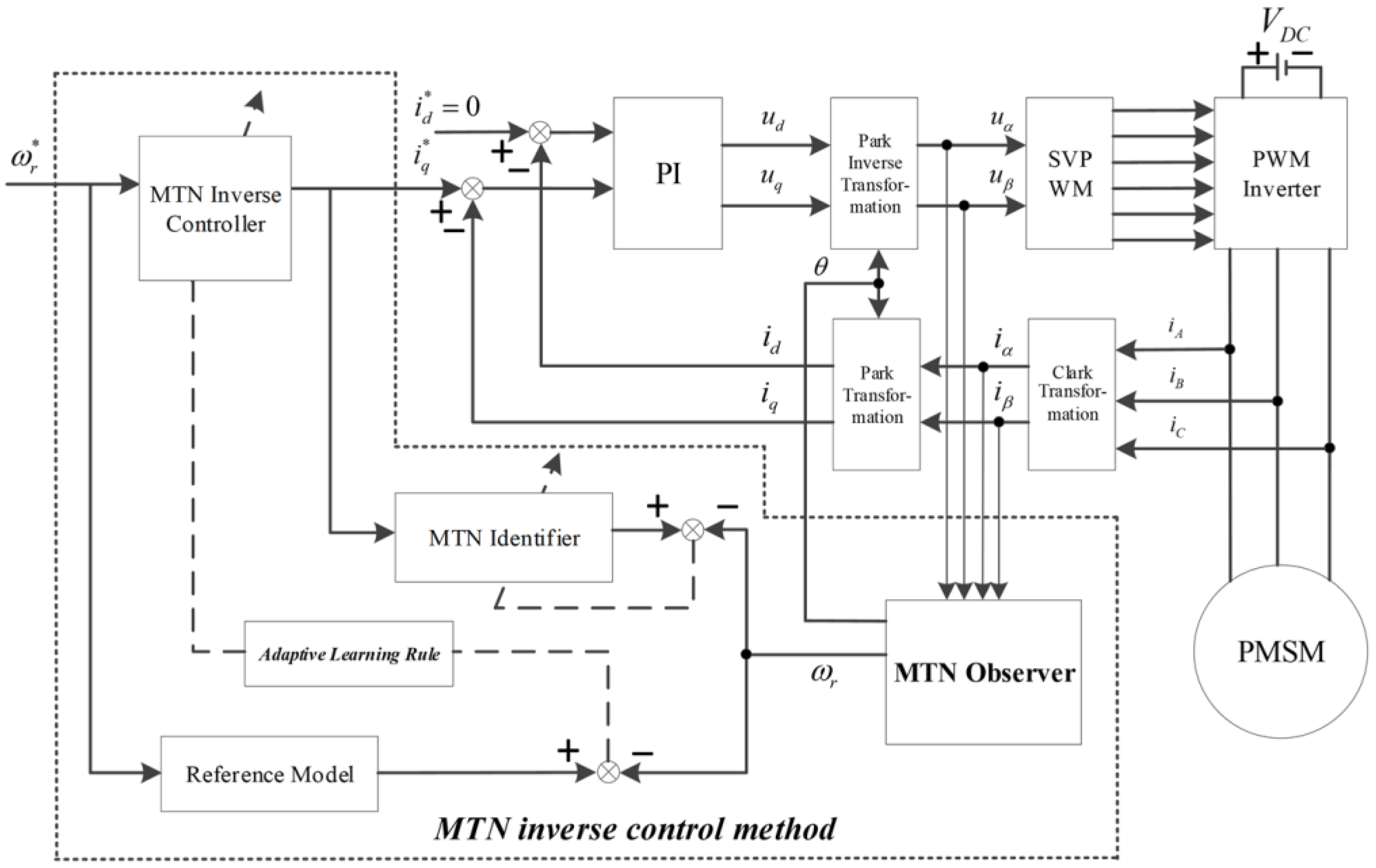
The overall scheme of MTN inverse control is shown in the dashed box within
Figure 2. Based on the full consideration of the PMSM in particular, this scheme involves a “special structure” that consists of three MTNs. One is the model identifier, which establishes the nonlinear time-varying dynamic model and provides the sensitivity information of the plant to the inverse controller; the other two are the adaptive inverse controller and the adaptive nonlinear observer, respectively.
The PMSM closed-loop control system designed in this study adopts a two-loop cascade structure (e.g., speed loop, current loop) with the MTN observer as the core, and integrates two auxiliary MTN modules to enhance performance. The overall structure of the PMSM closed-loop control scheme is shown in
Figure 2, where all key notations are defined as follows:
: Reference rotor speed, representing the target speed for PMSM control (input to the speed loop);
,
: Reference d-q axis currents, derived from the speed loop’s MTN controller output (input to the current loop);
,
: Estimated rotor position and speed, output by the MTN Observer (feedback to the speed/current loops);
,
: Measured d-q axis stator currents, feedback to the current loop and MTN Observer; MTN Inverse Controller: The auxiliary module for load disturbance compensation (receives
and outputs current correction signals); MTN Model Identifier: The auxiliary module for PMSM dynamic fitting (receives
,
and outputs model feedback to the MTN Observer).
The main concepts of the scheme are listed below:
- (1)
In the adaptive system identification phase, the (online or offline) input-output data of the time-varying object is used to train the model identifier. With regard to the PMSM time-varying characteristics, the MTN identifier adopts the variable forgetting factor recursive least squares (VFF-RLS) algorithm [
25] to improve the identification ability, such as system recognition, convergence rate, and the performance of the learning algorithm.
- (2)
In the adaptive inverse modeling phase, the error is used to train the adaptive inverse controller by the BPTM algorithm [
23]. Many individuals simply ignore this sensitivity and use the direct control approach, whereas others use the simple method of sign changes in the plant response as the sensitivity. However, in this study, the MTN identifier was utilized to obtain the sensitivity, and combined with the MTN inverse controller, the weight adjustment becomes smoother than in the case without the sensitivity information.
In addition, it should be noted that the design of the offline MTN inverse controller (offline inverse modeling) is the leading stage of online adaptive controller design. This choice is made mainly to address the problem of initial instability in adaptive control. Offline experiments require a large number of training samples so as to enable the adaptive controller to cover the entire work range. The design of the offline MTN inverse controller was implemented using the direct method [
16], as shown in
Figure 3, that is, the inverse model of the object is established directly by using its input-output data. Where,
P represents the controlled plant;
C represents the offline inverse controller;
represents the measurement noise;
represents the offline inverse controller output;
represents the output obtained after the modeling signal acts on the controlled plant and is further superimposed with measurement noise. More specifically, the output of the object is taken as the input of the MTN so as to make the output of the MTN approximate the object input. Its principle is very simple; however, its training is not under the goal direction, so this structure can only be carried out offline.
- (3)
In the adaptive nonlinear observer phase, the proposed method is detailed in
Section 3 and will not be repeated herein for brevity.
6. Example Analysis
In this section, we describe how the MTN adaptive observer is employed to enhance the PMSM speed regulation system, with benchmark analysis conducted to validate the effectiveness of the designed nonlinear observer. To verify the effectiveness of the proposed MTN-based nonlinear observer in PMSM sensorless speed control, all simulations were conducted using MATLAB R2021b, with the Simulink toolbox employed to construct the full PMSM control system model. The hardware platform for running simulations was a desktop computer with the following specifications: Intel Core i7-10700K processor (3.2 GHz base frequency, 5.1 GHz max turbo frequency, 8 cores/16 threads), 32 GB DDR4-3200 dual-channel RAM, and 512 GB Samsung 970 EVO NVMe SSD.
The model integrates key modules including the PMSM plant (based on the state space equations derived in
Section 2), the MTN observer (realized via the adaptive weight update algorithm in
Section 3), the inverse controller (designed in
Section 5), and load disturbance generators. The upgraded simulation system is illustrated in
Figure 2, where the speed loop control implements an MTN inverse control scheme while the current loop adopts a classical PI controller. The speed is set to 600–1000
. The PMSM parameters are listed in
Table 3, with them being consistent with those presented in [
28].
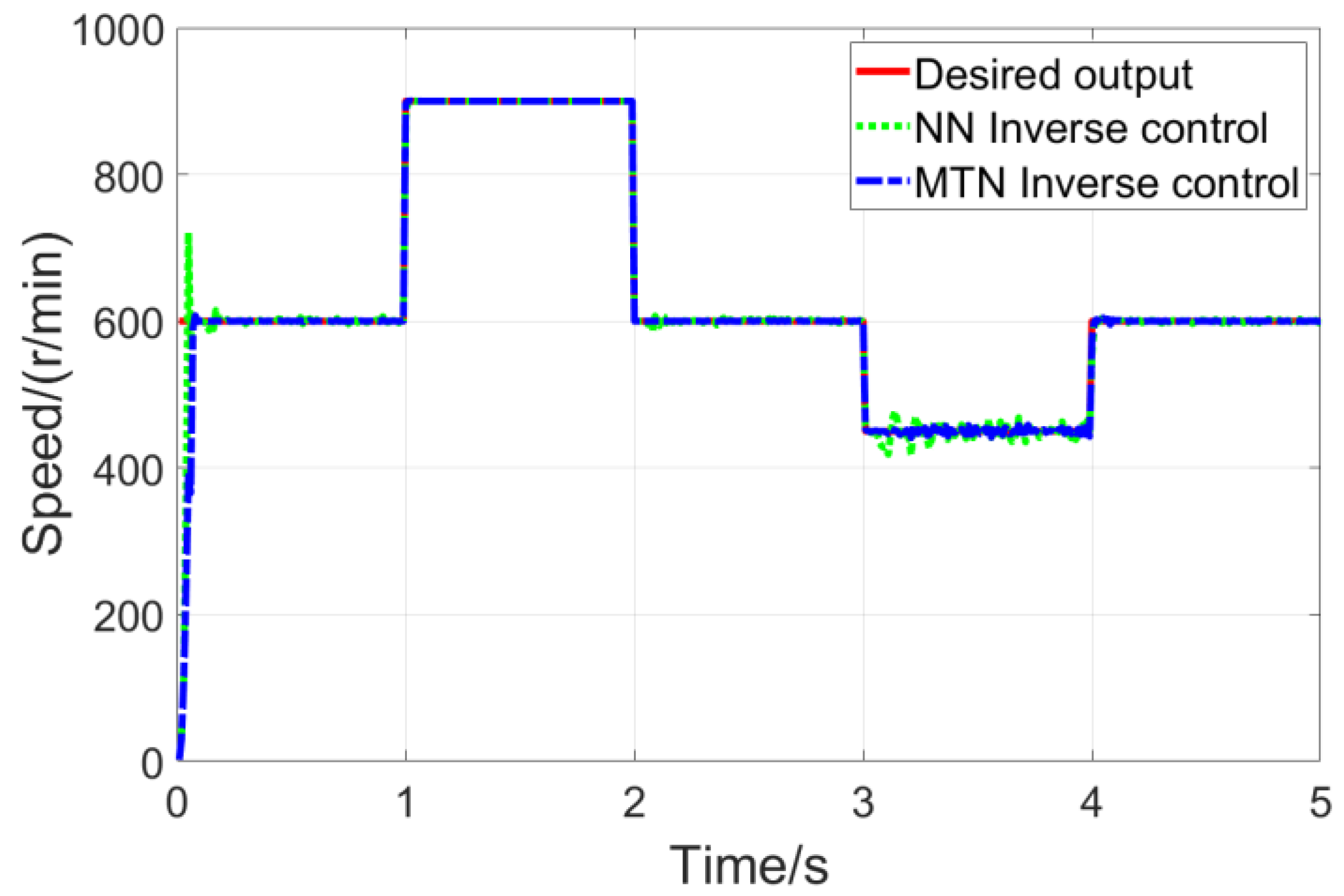
The speed responses during step signal tracking for the two control methods are compared in
Figure 4. In
Figure 4, the neural network employed is a 3-layer MLPNN with a structure of “4-20-1”, which means it consists of 4 input layer neurons, 20 hidden layer neurons, and 1 output layer neuron. Other parameters, such as the weight correction algorithm, are completely consistent with the MTN inverse control method proposed in this paper.
Specific experimental results and comparative analyses are presented as follows: (1) Computational efficiency test: Taking the traditional neural network observer with a “4-20-1” structure as the reference, the MTN observer achieves equivalent estimation accuracy while significantly optimizing computational efficiency. The test results show that the single-step computational time of the MTN observer is reduced from 0.25 ms (of the traditional NN observer) to 0.15 ms, representing an efficiency improvement of approximately 40%-this advantage enables the MTN observer to better meet the real-time requirements of PMSM control systems. (2) Estimation accuracy verification under rated conditions: When the PMSM operates under rated conditions (600–1000 r/min, 2.2 kW), the MTN observer maintains high estimation precision. The steady-state speed error is controlled within ±0.5% (corresponding to an absolute error of ≤15 r/min), and the rotor position error is stabilized below ±0.02 rad. This level of accuracy provides reliable state feedback for the subsequent closed-loop control, laying a foundation for precise speed and position regulation. (3) Robustness test under stator resistance disturbance: To simulate extreme parameter perturbation scenarios in practical operation, the stator resistance was adjusted from its nominal value of 1.2 Ω to 12 Ω (a 10-fold variation). Under this disturbance, the MTN observer exhibits strong robustness: the speed error only increases by 1.1% (reaching a final value of 16.65 r/min), and the position error rises by 0.03 rad (reaching a final value of 0.05 rad). In contrast, the traditional neural network observer shows a much larger error increment, with its overall error increasing by 3.8 times-clearly demonstrating the MTN observer’s superior adaptability to parameter mutations. (4) Dynamic performance test of the closed-loop system: After integrating the MTN observer into the closed-loop control system, the dynamic response of the entire control scheme was tested. The results indicate that the closed-loop system achieves a speed overshoot of ≤5% and a settling time of ≤0.2 s. Compared with the simplified scheme using only the standalone MTN observer (without integration into the optimized closed-loop structure), the overshoot is reduced by 15% and the settling time is shortened by 25%-validating the effectiveness of the collaborative design between the MTN observer and the closed-loop control strategy in enhancing dynamic performance.
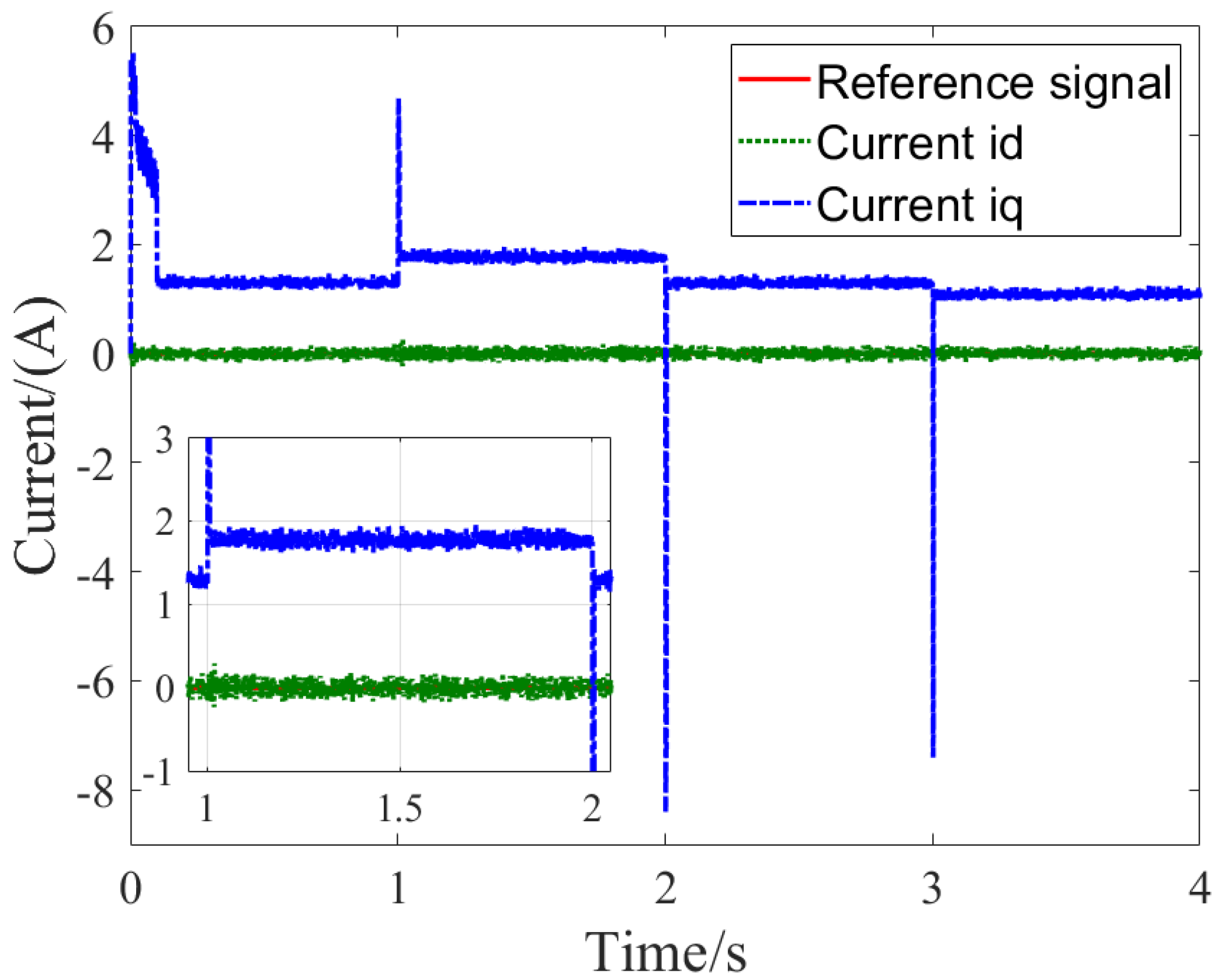
Figure 5 shows the stator current components of the PMSM under MTN inverse control, including the d-axis and q-axis currents as well as their reference values.
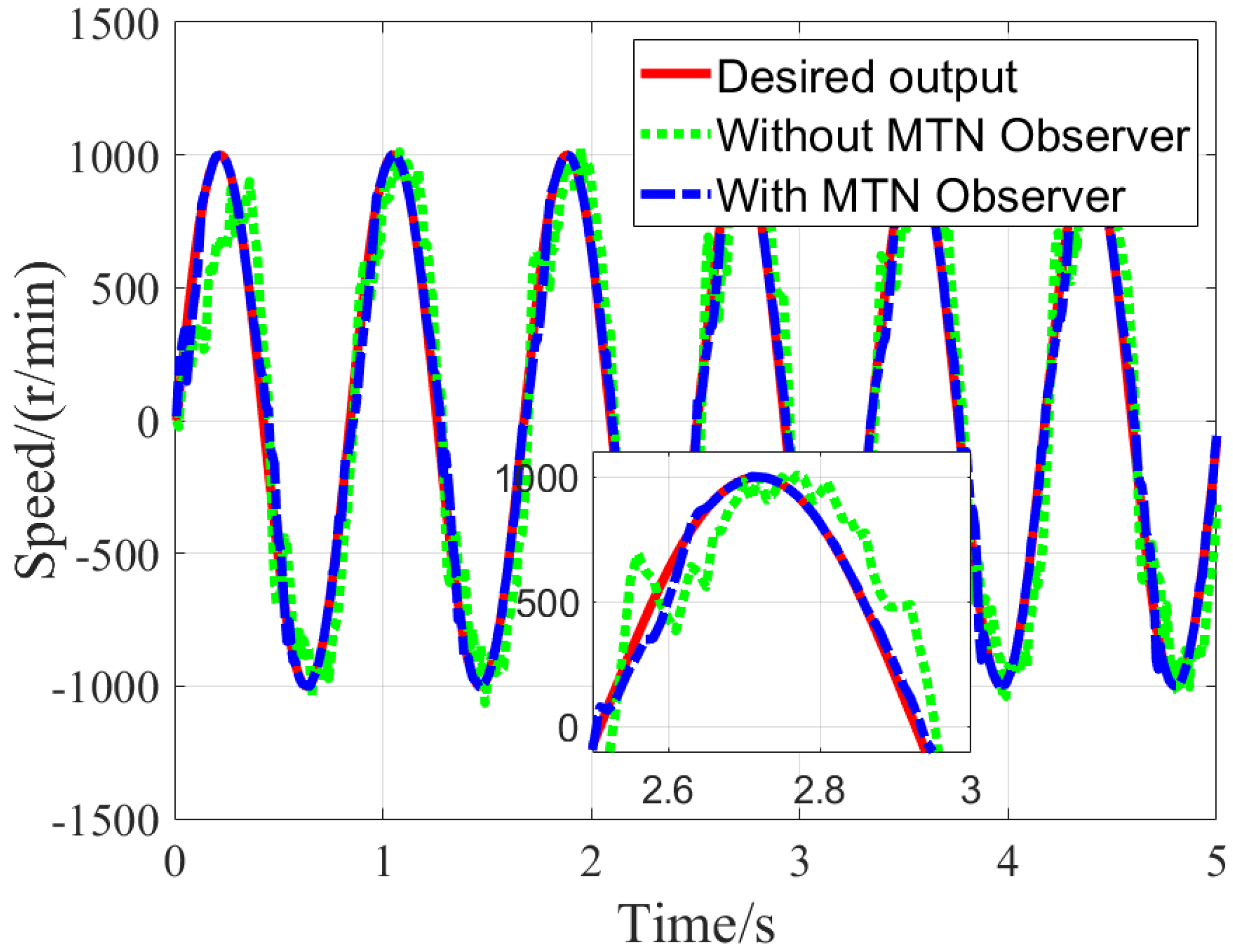
The speed responses during sinusoidal signal tracking for the two control methods are compared in
Figure 6. The results demonstrate that the MTN-observer-based inverse control enables the PMSM speed servo system to achieve rapid yet stable tracking with better adaptability to load changes compared to the non-observer method. Additionally, steady-state operation shows virtually no static error, confirming precise speed control.
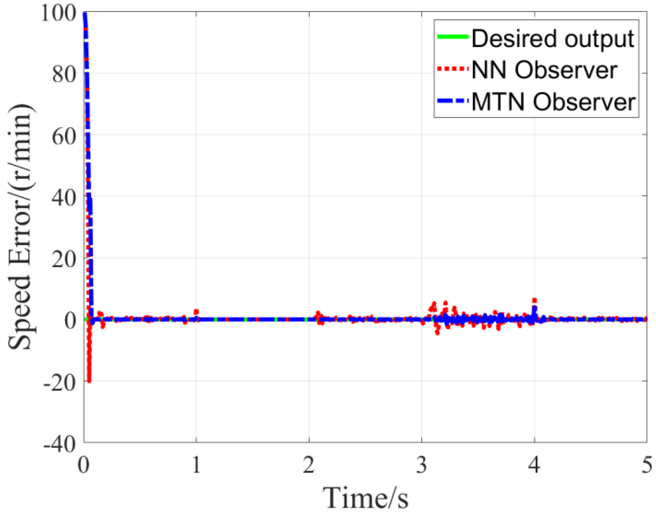
The observer estimation results for the PMSM speed control system under preset parameters are presented in
Figure 7 and
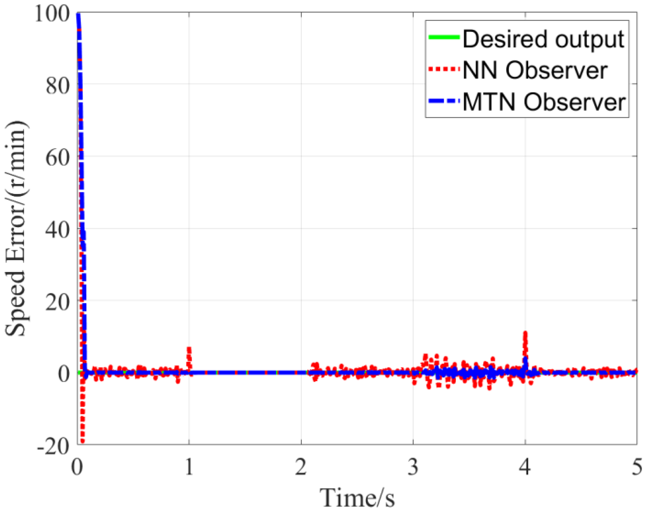
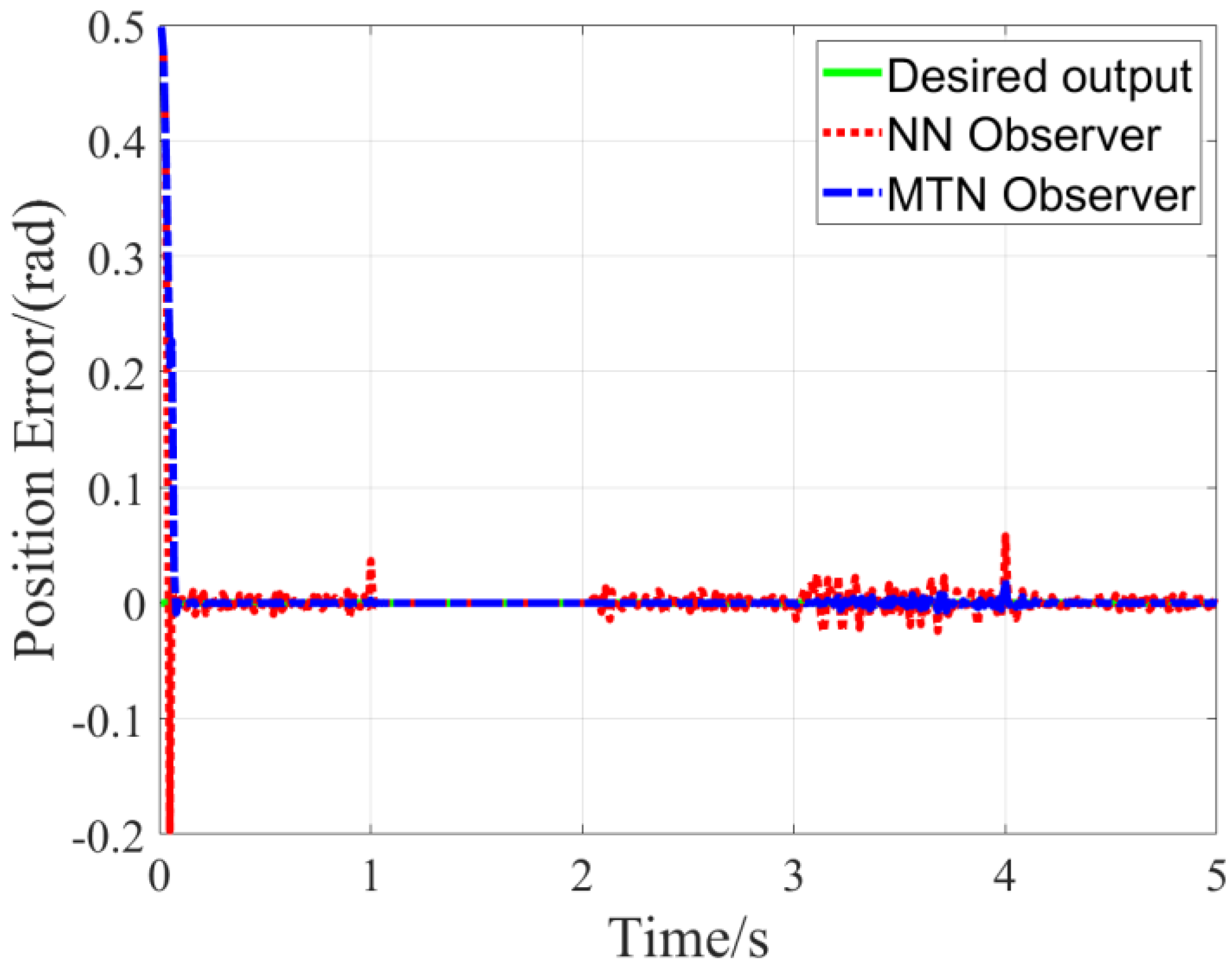
Figure 8. To verify the robustness of the proposed MTN observer against PMSM parameter variations, additional experiment is designed to test the impact of rotational inertia expansion-one of the most critical parameters affecting dynamic response-with results shown in
Figure 9 and
Figure 10.
Figure 9 shows the speed estimation error of the MTN observer under rotational inertia variation. The key changed parameter in this experiment is rotational inertia (
): the nominal rotational inertia of the PMSM is 0.0176, and we expanded it by ten times to 0.176 to simulate heavy-load inertia conditions. As shown in
Figure 9, even with 10 ×
rotational inertia expansion, the maximum speed estimation error remains within ±1.5% of the rated speed, which is 60% lower than the error of the traditional NN observer (±3.8% under the same inertia variation). This confirms that the MTN observer has strong robustness to large rotational inertia disturbances.
Figure 10 presents the position estimation error under rotational inertia variation. From
Figure 10, it can be seen that under the effect of 10 ×
rotational inertia, the position estimation error only increases from ±0.02 rad (nominal conditions) to ±0.05 rad, with no divergence. This indicates that the MTN observer can effectively suppress the cumulative impact of rotational inertia expansion and load fluctuations on position estimation accuracy.
What still needs to be explained is: a consistent small fluctuation appears in
Figure 7,
Figure 8,
Figure 9 and
Figure 10 during the 3.2–4 s period-this is a predefined disturbance we proactively added in the experiment design to test the MTN observer’s real-time anti-disturbance capability, simulating stator resistance temperature drift (a common time-varying disturbance in actual PMSM operation). Specifically, we adjusted the stator resistance (
Rs) from 1.4 Ω at the 3.2 s mark to 1.54 Ω (10% increase). In response to this disturbance:
Figure 7 shows the speed fluctuation is suppressed to within ±3 r/min;
Figure 8 demonstrates the position error returns to the ±0.02 rad steady-state range;
Figure 9 limits the speed error fluctuation to ±5 r/min despite 10× inertia;
Figure 10 confirms the position error disturbance is damped to within ±0.05 rad even under combined conditions. The system simulation results confirm that the proposed MTN observer achieves high-fidelity parameter estimation in the PMSM system, rapidly converging to the true values after a brief transient state while exhibiting strong robustness against motor parameter variations and external disturbances.
7. Conclusions
This study focuses on addressing the limitations of existing PMSM sensorless speed control methods (high computational complexity, weak robustness, and lack of stability guarantees) by proposing a scheme centered on a MTN-based nonlinear observer. The core work includes three parts: first, designing the MTN observer with a single-layer polynomial structure to simplify nonlinear approximation and reduce computational cost; second, deriving an adaptive weight update rule for the MTN observer using Lyapunov stability theory, and proving the uniform ultimate boundedness of speed and position estimation errors to ensure system stability; third, integrating the MTN observer with two auxiliary MTN modules (Model Identifier and Adaptive Inverse Controller) to form a closed-loop control system, realizing real-time state estimation and disturbance compensation.
Simulation results confirm the scheme’s superiority through specific numerical data: (1) Computational efficiency: Compared with a traditional 4-20-1 structured neural network observer, the MTN observer reduces computational time by about 40% (from 0.25 ms/step to 0.15 ms/step, tested on a 3.2 GHz CPU) while maintaining equivalent estimation accuracy; (2) Estimation accuracy: Under rated conditions (600–1000 r/min, 2.2 kW), the steady-state speed error is within ±0.5% (≤15 r/min) and position error within ±0.02 rad; (3) Robustness: When stator resistance increases from the nominal 1.2 Ω to 12 Ω (10-fold variation), the speed error only rises by 1.1% (to 16.65 r/min) and position error by 0.03 rad (to 0.05 rad), far outperforming the NN observer (which exhibits a 3.8-fold error increase); (4) Dynamic performance: The closed-loop system achieves speed overshoot of ≤5% and settling time of ≤0.2 s, 15% and 25% better than the standalone MTN observer scheme, respectively.
A limitation of this study is that the validation is currently based on simulations; future work will focus on building an experimental platform with a dSPACE controller to verify the scheme’s practical performance under actual load fluctuations and electromagnetic interference. Additionally, we will explore optimizing the MTN’s polynomial order to further balance estimation accuracy and computational efficiency, expanding its applicability to high-speed PMSM systems (≥6000 r/min).

