Article

Numerical Study on Free Convection in an Inclined Wavy Porous Cavity with Localized Heating

by
Sivasankaran Sivanandam
1,2,*,
Huey Tyng Cheong
3 and
Aasaithambi Thangaraj
4
1
Department of Mathematics, King Abdulaziz University, Jeddah 21589, Saudi Arabia
2
Department of Mathematics, Saveetha School of Engineering, SIMATS, Chennai 602105, India
3
School of Mathematical Sciences, Sunway University, Kuala Lumpur 47500, Malaysia
4
Department of Mathematics, Sri Shanmugha College of Engineering and Technology, Sankari 637304, India
*
Author to whom correspondence should be addressed.
Modelling 2025, 6(2), 30; https://doi.org/10.3390/modelling6020030
Submission received: 28 January 2025 / Revised: 23 March 2025 / Accepted: 2 April 2025 / Published: 5 April 2025

Abstract

:
The goal of the present investigation is to explore the heater position and tilting angle of geometry on a buoyant convective stream and energy transport in a tilted, curved porous cavity. This work can be utilized in the field of solar panel construction and electrical equipment cooling. Since no study has explored the impact of the heater location in an inclined wavy porous chamber, three locations of the heater of finite length on the left sidewall, viz., the top, middle, and bottom, are explored. The stream through the porous material is explained by the Darcy model. The upper and lower walls, as well as the remaining area in the left wall, are covered with thermal insulation, while the curved right sidewall maintains the lower temperature. The governing equations and related boundary conditions are discretized by the finite difference approximations. The equations are then iteratively solved for different heater positions, inclinations, Darcy–Rayleigh number (RaD), and corrugation of the right walls. It is witnessed that the heater locations and cavity inclinations alter the stream and thermal fields within the curved porous domain. Furthermore, all heating zones benefit from improved heat conduction due to the right sidewall’s waviness and the tilted porous domain.

1. Introduction

Researchers have published a wealth of research on energy transport through a porous matrix and natural convection flow in recent decades [1,2]. Its many uses in modern-day technology have improved our knowledge of liquid and thermal movement inside geothermal reservoirs, enhanced solar collector designs, and the cardiopulmonary system [3,4]. Pandit et al. [3] and Biswas et al. [4] presented significant new insights on buoyant convection across a porous matrix. A cavity with uneven wall(s) will impact the system’s aggregate energy transport rate, as it can raise or drop the heat exchange surface area [5,6,7]. Using the Darcy model, Murthy et al. [8] examined a buoyant convective stream in a porous chamber with a heated, undulating bottom wall. For example, Rathish Kumar [9] and Rathish Kumar and Shalini [10,11,12] looked at convection in cavities with curved left sidewalls and different thermal boundary conditions, like the heat flux [9], constant wall temperature [10], and linear wall temperature [11,12]. Rathish Kumar and Shalini [10,11,12] observed that the higher amplitude and undulation of the undulating left sidewall impede the heat transmission along a hot surface. Khanafer et al. [13] also examined a porous domain with a heated and curved left sidewall, utilizing multiple flow models for the porous medium. Bhardwaj and Dalal [14] and Bhardwaj et al. [15] examined buoyant convective flow in a right-angled triangular chamber filled with a porous medium. The bottom wall exhibits a sinusoidal temperature, while the left sidewall displays a wave pattern. According to Bhardwaj et al. [15], the undulation accelerates the transfer of heat within the cavity.
The cavity’s angle, which alters the direction in which the walls are either hot or chilly, could affect the overall energy transport efficiency of a system [16,17,18]. Adjlout et al. [19] and Sabeur-Bendehina et al. [20] studied buoyant convection in an inclined depression with a distinct heating effect on the wave on the right sidewall. Adjlout et al. [19] found that positioning the cold wall higher than the hot, curved wall minimizes the heat transmission rate due to the rise in undulation on the heated wall. Sabeur-Bendehina et al. had accounted for the sinusoidal temperature on the vertical cold wall and curved hot wall [20]. They found that when sinusoidal heating and cooling occurred, both the average temperature and temperature rose. Varol and Oztop [21] investigated a buoyant convective stream in a tilted, curved chamber with differential heating on the curved walls. Furthermore, Varol and Oztop [22] used an inclined rectangular chamber with differently heated sidewalls to compare the results. They discovered that compared to the flat cavity, the energy transport rate is higher in the undulating cavity. Mekroussi et al. [23] explored a mixed convective stream in a tilted cavity, which features a heated, curved lower wall and a sliding cover on the top wall.
Bourich et al. [24] looked into a double-diffusive convective stream inside a square porous chamber with partial heating from below. They discovered that asymmetric bicellular flow occurs inside the hollow when they shift the heating point to the right of the bottom wall. Zhao et al. [25] studied double-diffusive convection in a square porous domain with some heating on the right sidewall. They used the Darcy and Darcy–Brinkman models to perform this. They discovered that placing the heater near the base of the right sidewall results in the strongest circulation. Varol et al. [26] then looked at Darcy flow through a porous square chamber with three isothermal heaters on the left sidewall. Bhuvaneswari et al. [27] investigated buoyant convection inside a rectangular porous chamber with five different heating–cooling pairs along the vertical sidewalls. They found that the center–center pair offers the best heat transmission. Sivasankaran et al. [28] conducted an investigation into two heat flux sources on the left sidewall of a tall, buoyant, rectangular porous cavity that undergoes convection. They found that the rate of energy transport with the lower heater was superior to that of the upper heater, except for the fact that it was longer.
In addition to square and rectangular cavities [29,30], partial heating has also been studied for triangular [31], trapezoidal [32], and wavy cavities [33,34]. Sun and Pop [31] investigated buoyant convection inside a right-angled, triangular, porous container loaded with a nano liquid substance. Furthermore, Sun and Pop [31] examined the inclination of the triangular cavity and found that the maximum average energy transport rate occurs at an angle of 150°. Ahmed et al. [32] computed a buoyant convective stream in a tilted square porous domain with corner heating. Cho [31] investigated spontaneous convection in a nano liquid-filled square hole by partially heating the left wall’s cavity surface. It has been shown that when the wavelength and amplitude of the cavity surface rise, the N u ¯ drops.
The authors conducted a thorough literature search and discovered that there are only a handful of publications focused on buoyant convection in an inclined, porous domain. No study has explored the impact of the heater location and inclination of the chamber on convection in an inclined wavy porous chamber. So, this numerical study focuses on how the tilting angle of the cavity and the locations of the heater on the left sidewall affect the flow of buoyant convection and the movement of energy in the wavy porous cavity. The corresponding contours depict the flow pattern and temperature distribution of the cavity, while the subsequent section presents the energy transport rates.

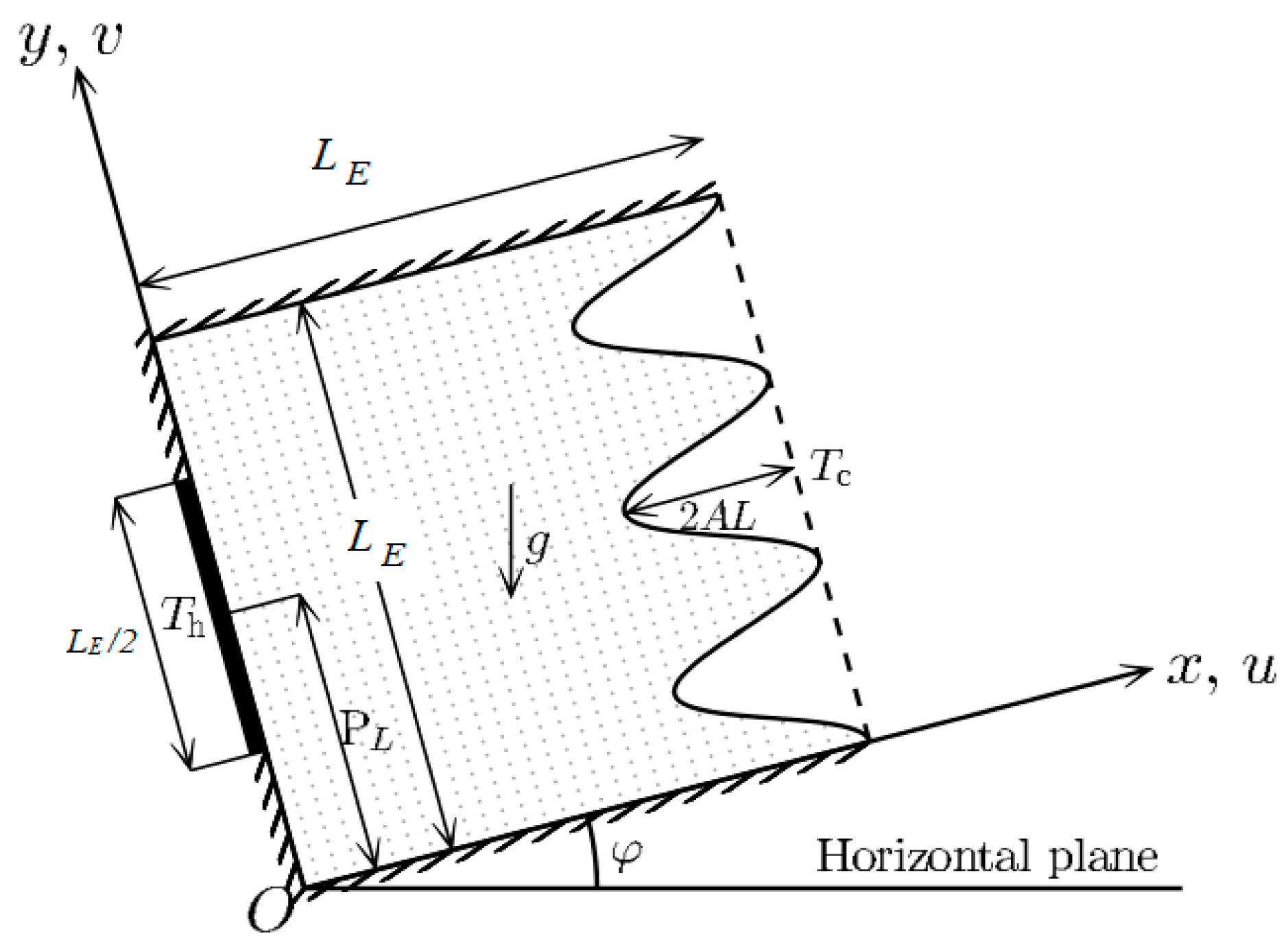
2. Mathematical Modeling and Formulation

Figure 1 demonstrates the ( x , y ) coordinate system and the schematic of the physical model of a 2D square enclosure of size LE. The acceleration of gravity, g, operates vertically downward, while the velocity components, u and v, point in the respective axis of the x and y directions. The wavy form of the cavity’s right wall with an amplitude A and λ for the number of undulations is taken into consideration. Moreover, the cavity is tilted at an (acute) angle of ϕ with respect to the x-plane (y = 0). The heater of size LE/2 is placed on the left wall at a higher temperature Th, and cools the opposing curved right sidewall at a constant temperature Tc. We determine the heater’s center by selecting three different locations on the left sidewall. Each point corresponds to a distinct heating area along the sidewall. The heater’s locations (PL) are LE/4 for bottom heating, LE/2 for middle heating, and 3LE/4 for top heating. The remaining area on the left wall is adiabatic while changing the heater location from top to bottom.
An incompressible and Newtonian fluid-saturated closed porous medium fills the cavity. In contrast to buoyancy, the fluid’s density also exhibits minimal variation, and its characteristics remain constant. In other words, the Boussinesq estimation is valid when the body force operates, as the buoyancy force is a consequence of the density fluctuation with the temperature. The flow is presumed to be steady, laminar, and incompressible. The viscous dissipation is negligible. In order to characterize fluid flow through a porous medium, the Darcy model is employed, as it is presumed that the medium is homogeneous, isotropic, and in thermal equilibrium with the local fluid. The principles of conservation for momentum, energy, and mass form the model.
u x + u y = 0 ,
u = K µ P x + K µ   T     T c β g ρ   sin φ ,
v = K µ P y + K µ   T     T c βg ρ   cos φ ,
u T x + v   T y = k ρ c p 2 T x 2 + 2 T y 2
where µ, P, ρ, β, k, K, and Cp stand for the dynamic viscosity, pressure, density, thermal expansion coefficient, thermal conductivity, porous medium’s permeability, and heat capacity at a constant pressure, respectively.
The cavity’s boundary conditions are as follows:
u = v = 0 : on all solid boundaries , T = T h   :   on   x = 0 ,   P L 1 2 · L E 2   y     P L + 1 2 · L E 2 , T x = 0 :   on   x = 0 ,   0 < y < P L 1 2 · L E 2   and   P L + 1 2 · L L E 2 <   y < L E , T = Tc   :   on   x = L E L E 1   c o s ( 2 λ π y L E ) A , L E   y   0 , T y = 0 :   on   y = L E   and   0 , L E   x   0 ,
where lower, center, and upper heating zones are represented, respectively, by PL = L E /4, L E /2, and 3 L E /4. The rate of energy transport is one of the variables used to assess the significance of a thermal energy transport across the porous domain. Thus, in the current investigation, the heat transmission rate is used as an evaluation. The averaged heat transmission rate ( q ¯ ) and the local energy transport rate (q) along the heater on the sidewall are calculated as follows:
q = k T n ,    
q ¯ = 1 L E 2 P L 1 2 · L E 2 P L + 1 2 · L E 2 q d y ,
where n is the sidewall’s normal, or n = x in the case of the left wall’s (heater) computation.
The x-derivative of the v-momentum Equation (3) is subtracted from the y-derivative of the u-momentum Equation (2) to yield the stream function equation. Next, the equations’ velocity components are given in terms of the stream function, and they are as follows:
                        u = y ,         v = x .                                  
The physical values of the variables concerned, as well as the regulating model and boundary constraints, must be known in order to solve the system of PDEs. Dimensionless form can be obtained by scaling the dimensional regulating equations and boundary conditions with appropriate dimensionless variables, leaving fewer variables as dimensionless integers. Consequently, the dimensionless variables listed below are suitable for this investigation:
X = x L E ,         Y = y L E ,       Ψ = α ,       Θ = T T c T h T c ,   R a D = K β g ( T h T c ) L E α v ,
where R a D is the Darcy–Rayleigh number based on cavity width L E and α = k/ ρ c p is the thermal diffusivity, respectively. The dimensionless governing equations that result from substituting the dimensionless variables (9) into the model Equation (1) through (4) and the boundary settings (5) are as follows:
2 Ψ X 2 + 2 Ψ Y 2 = R a D Θ X cos φ Θ Y sin φ ,
2 Θ X 2 + 2 Θ Y 2 = Ψ Y Θ X Ψ X Θ Y ,
along with the matching boundary conditions,
Ψ = 0 : on all solid boundaries , Θ = 1 :   on   X = 0 ,   P L L E 0.25   Y     P L L E + 0.25 , Θ X = 0 :   on   X = 0 ,   0 < y < P L L E 0.25   and   P L L E + 0.25 < Y < 1 , Θ = 0   :   on   X = 1     1 c o s ( 2 π λ Y ) A , 1   Y   0 , Θ Y = 0 :   on Y = 1   and   0 , 1   X   0 ,
where bottom, middle, and top heating are represented by PL/ L E = 1/4, 1/2, and 3/4, respectively.
The Nusselt number indicates the fluid layer’s energy transport ratio between convection and conduction, which is a measure of the dimensionless energy transference rate. Thus, the averaged Nusselt number ( N u ¯ ) and the local Nusselt number ( N u L o c a l ) along the heater on the sidewall are as follows:
N u = Θ N ,        
N u ¯ = 2 P L L E 1 4 P L L E + 1 4 N u   d Y ,          
where the sidewall’s normal is represented by N = n / L E .

3. Method of Solution

The mesh division approach is employed to subdivide the curved cavity for numerical solutions. The curved actual domain is mapped using this method to a square solution domain with consistent step sizes and uniform mesh. The following algebraic equations are related to the transformation of the curved cavity from a square (computational) coordinates (ξ, η) to the physical coordinate system (X, Y):
ξ = X 1     A   ( 1   c o s ( 2 π λ Y ) ) , η = Y
Completing computations in the solution domain requires stating the governing equations and boundary conditions in terms of the computational coordinate system. Therefore, the governing equations are transformed as follows:
a 2 Ψ ξ 2 + 2 b   2 Ψ ξ   η + c 2 Ψ η 2 + d Ψ ξ + e Ψ η = R a D ξ X cos φ ξ Y sin φ Θ ξ + η X cos φ η Y sin φ Θ η ,
a 2 Θ ξ 2 + 2 b   2 Θ ξ   η + c 2 Θ η 2 + d Θ ξ + e Θ η = f Ψ η Θ ξ Ψ ξ Θ η ,
where
a = ξ X 2 + ξ Y 2 ,   b = ξ X η X + ξ Y η Y
c = η X 2 + η Y 2 ,   d = ξ X X + ξ Y Y
e = η X X + η Y Y ,   f = ξ X η Y + ξ Y η X
and the matching boundaries values are as follows:
Ψ = 0   : on all solid boundaries , Θ = 1   : on   ξ = 0 ,   P L L E 0.25   η     P L L E + 0.25 , ξ X Θ ξ   + η X Θ η = 0 : on   ξ = 0 ,   0 < η < P L L E 0.25   and   P L L E + 0.25 < η < 1 , Θ = 0   : on 0 η 1 , ξ = 1 , ξ Y Θ ξ   + η Y Θ η = 0 : on   η = 1   and   0 ,   0   ξ 1 ,
Furthermore, local and averaged Nusselt numbers for the computational coordinate system are as follows:
N u =   Θ ξ ξ X cos Φ ξ Y sin Φ + Θ η η X cos Φ η Y sin Φ ,
N u ¯ = 2 P L L E 1 4 P L L E + 1 4   1 J   ξ X   N u   d η ,
where J = 1 / (   X ξ   Y η X η   Y ξ ) is the Jacobian of the transformation and ϕ is the sidewall inclination from the y-axis, or ϕ = 0 0 for the calculation along the left wall.
Using the finite difference approximations, the modified governing Equations (16) and (17) and the accompanying boundary conditions (18) are now discretized. The second-order central difference method is employed to approximate the inner coordinates, while the boundary points are approximated using the second-order backward and forward methods. The successive-under-relaxation method (SUR) is used to solve the energy problem (17) and the stream function Equation (16). To satisfy the convergence condition, the equations are iteratively solved, until
ε = max i , j ς i , j   n + 1 ς i , j   n < 10 6 ,
where (n) indicates the number of iterations, i and j provide discrete points in the (ξ, η) coordinate system, and ς is either Ψ or Θ. The Trapezoidal rule is utilized to compute the N u ¯ .
The ξ and η directions of the computational (domain) grids are equally spaced. For simulations, an appropriate grid size is determined using the N u ¯ . For heater length of L E / 2 at RaD = 103, mesh independence analysis is performed for the square (λ = 0, A = 0) and curved (λ = 5, A = 0.25) cavities. Mesh sizes that are taken into consideration range from 60 × 60 to 300 × 300. Table 1 presents the tabulated findings, which indicate that the 150 × 200 grids are adequate for the simulations. After that, the numerical code is confirmed using the literature on differentially fully (isothermal) heated square porous cavities with no inclination. Table 2 displays the comparison, and the outcomes look good for the next simulations.

4. Results and Discussion

A numerical analysis of buoyant convection in a curved porous chamber with localized heating on the left wall was completed to explore the impact of the heater locations, tilting angle of geometry, and right sidewall waviness on the energy transportation and stream within the porous enclosed domain. The amplitude ( A ) and number of undulations ( λ ) of the wavy wall, heater’s position ( P L ), inclination angle ( φ ), and Darcy–Rayleigh number ( R a D ) are the pertinent parameters involved in the study. The numerical simulations are performed in the range of 0 λ 3 , 0 A 0.15 , 0 ° φ 90 ° , 10 R a D   10 3 , and P L = 1 4 , 1 2 , 3 4 , respectively.

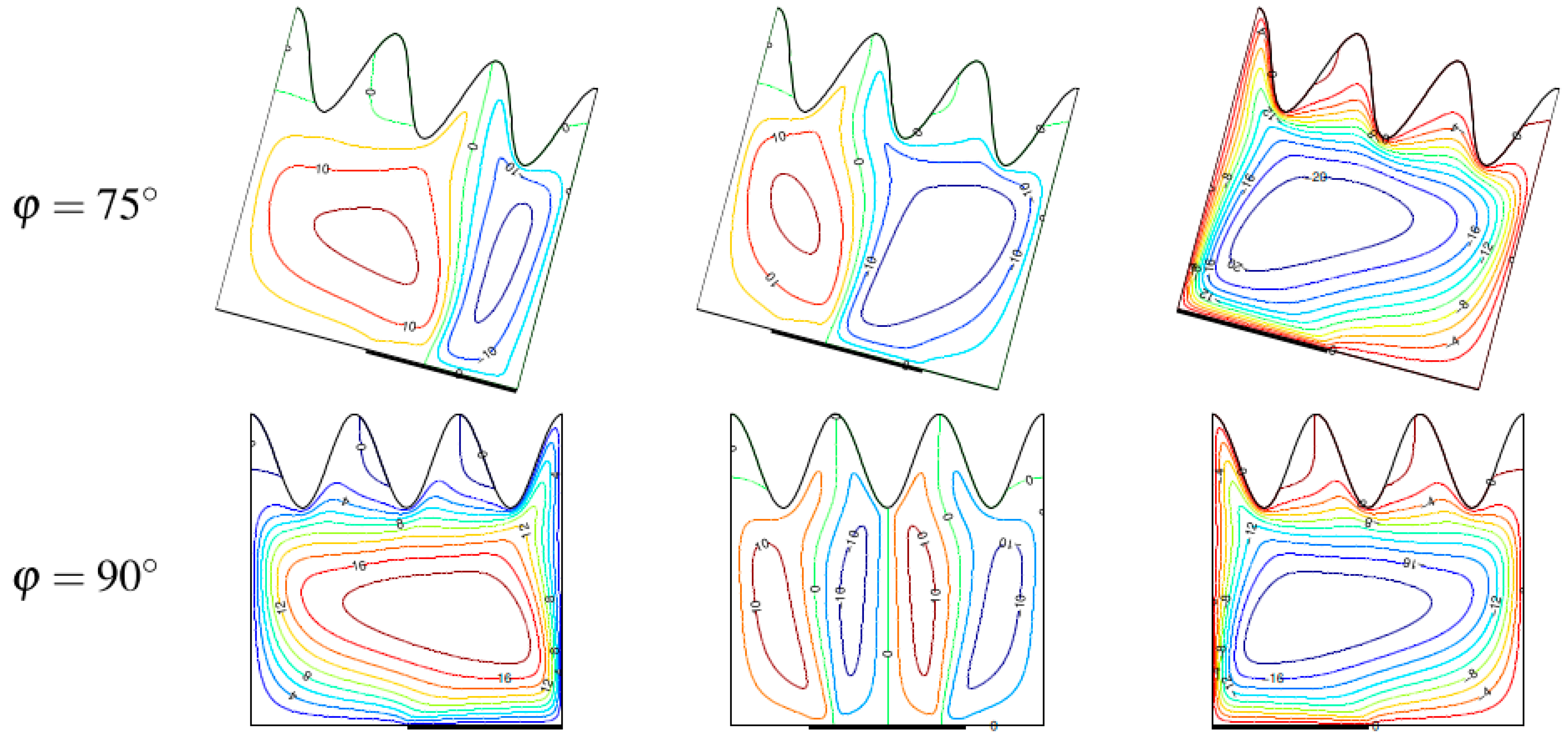
4.1. Thermal Distribution

The thermal distributions within the curved porous domain with waviness λ = 3 and A = 0.15 at R a D = 10 3 for diverse heater places and the tilting angle of the cavity are displayed in Figure 2. The temperature contours are first observed to extend from the heat source to sink (cold wall), and the cavity’s thermal stratification almost precisely parallels the horizontal plane. This suggests that when RaD = 103, the convective mode is the predominant route of heat transmission across the domain. It is also observed that the area within the curved cavity where the temperature field is occupied is determined by the heater’s location on the left sidewall. In other words, during bottom heating, the temperature field is evenly spread across the cavity when φ = 0 ° . In contrast, while moving the heater from the center to the top, the heater’s leading edge starts the process of thermal stratification, which results in the cold fluid saturation of the surrounding area. Moreover, the overall temperature distribution within the curved porous domain is impacted by the cavity inclination. The isotherms within the cavity move to align with the horizontal plane when the cavity is inclined. At φ = 75 ° and φ = 90 ° , the structure of the heater resembles a plume, and the isotherms line up with the adiabatic walls. The isotherms’ clustering illustrates the formation of thermal boundary layers (TBLs) along the heat source. Furthermore, the isotherms are concentrated in the area between the second and third undulations of the cold wall, or at the upper-right corner of the cavity. TBLs form in particular regions, indicating the presence of a strong temperature difference.

4.2. Flow Field

The streamlines in Figure 3 illustrate the influence of the heater’s location on the left wall on the flow field within the porous cavity and the stream’s circulation strength. During bottom heating, the flow occupies the full cavity and circulates in a clockwise manner when φ = 0 ° . When top and center heating occur, there is a clockwise movement of liquid; nevertheless, the velocity boundary layer starts at the heater’s leading edge, and below that, the flow is stationary because the area is primarily filled with cold liquid, as shown in Figure 2. The center of the cavity is where the flow’s inner core can be found when heating from the middle; the mid-height of the heater is where it is located when heating from the center and its top. When the heater location is on the left sidewall, the flow circulation strength is at its strongest and progressively decreases as it rises. When the hollow is inclined from 0 ° to 45 ° , the flow is unicellular, and when the heating is center and bottom, a dual-cell arrangement is formed at φ = 75 ° . When the horizontal plane and the heater are parallel, or φ = 90 ° , the flow is multicellular. As seen in Figure 2, the creation of a plume-like structure in the temperature field corresponds with the formation of numerous flows inside the cavity. As the charged liquid particles climb along the wall until they come into contact with the adiabatic top wall due to a drop in density, the data indicate that lower heating on the left wall causes the liquid to current from the cavity’s bottom. The heated liquid cools along the curved wall, causing the denser liquid particles to settle to the cavity’s bottom. As a result, the stream in a single cell in a clockwise manner throughout the entire cavity. When center and top heating is used, the liquid is only heated in close proximity to the source; below that point, the liquid remains stagnant and cold in the area. At φ = 75 ° and φ = 90 ° angles of tilt, the heat source is nearly parallel to the x-plane. Here, along the heater, flow separation occurs, resulting in several flows.

4.3. Heat Transfer Rate

The fluctuation of N u for diverse heater positions and the tilting angle of the cavity at R a D = 10 3 is plotted along the heater in Figure 4. All in all, the observation demonstrates that at all heater positions of the cavities with tilt angles φ = 45 ° and φ = 0 ° , the energy transport rate asymptotically approaches its minimum value at the heater’s end and declines dramatically from the heater’s leading edge. Depending on the heating locations, the   N u change occurs when φ = 90 ° . When lower heating is used, the rate of energy transport rises progressively along the heater. As it approaches the heater’s terminus, the heat transmission rate progressively decreases until it abruptly rises there. The reflection of the lower heater case along the mid-height of the domain determines the local energy transport rate of the upper heating system. This indicates that the heat transfer rate starts to decrease at the heater’s leading edge and continues to do so steadily as it approaches the heater’s terminus. The local energy transport for center heating is symmetric at the mid-height of the domain. From the heater’s leading edge to its mid-length, the heat transmission rate rapidly decreases before it rises towards the heater’s finish. It is seen that the points where the heater has the least energy transport are those where the plume structure forms in the thermal pattern depicted in Figure 2 and where the stream separates, as shown in Figure 3.
In examining the impact of the right wall’s waviness on the local Nusselt number fluctuation, it is evident that for both λ = 2 and 3, at every heating position along the heater, but especially at the leading edge, the local energy transport rate rises as the amplitude of the curved right sidewall rises. This is because the raised amplitude of the curved right sidewall upsurges the possibility of heat exchange between the walls, thereby shortening the distance between the cold wall and the heater. Compared to bottom and center heating, the leading edge of the heater clearly exhibits a higher rate of heat transmission due to the two undulations on the right sidewall. The right sidewall’s concave parts and the heater’s edges are close together, which raises the rate of heat transmission at those locations. When the heater is placed at the lower and center location, the convex part of the curved wall and the concave area for upper heating are always level with the heater’s leading edge. However, the right sidewall is curved and features three undulations. Because of this, when the heating site shifts from the bottom to the top, the leading edge’s energy transport rate rises. Consequently, the undulation of the right wall also clearly shakes the distribution of the rate of heat energy transport.
The heater’s N u ¯ ,   as well as how it changes with cavity inclination, right wall undulations, places where heating occurs, and RaD when A = 0.150, are displayed in Figure 5. The overall findings demonstrate that the average heat dissipation rate rises with the number of undulations, regardless of cavity inclinations, heating locations, or RaD. The reason for this is that greater undulations on the right sidewall’s curved structure raise the wall’s surface area, which in turn accelerates the pace at which heat is conveyed from the heater to the side of the cold wall. The maximum average energy transport rate is recorded at RaD = 10, when center heating is followed by lower heating and upper heating. The minimum average energy transit rate is found for top heating for φ = 0 °   &   45 ° and above, and for bottom heating for φ = 60 ° and higher. For φ = 0 °   &   45 ° and above, upper heating has the minimum average energy transport rate; lower heating has the minimum average energy transport rate from φ = φ = 60 ° and upwards. The average energy transport rises somewhat with the cavity inclination variation and subsequently decreases to a minimum at φ = 90 ° . When φ = 0 ° ,   15 ° ,   &   30 ° for upper, center, and lower heating, respectively, the maximum energy transport is achieved. A low Darcy–Rayleigh number (RaD = 10) indicates a low buoyancy to viscous force ratio. Center heating is the most efficient method of heat transmission at low RaD because it can disperse heat from the heater throughout the entire domain due to its high viscosity, which facilitates conduction of heat from the source to liquid particles. Additionally, when the cavity is sloped, the heated/cold walls’ orientation with regard to gravity is changed. The energy transport rate within the porous domain is higher when it is somewhat inclined, meaning that the heating direction is angled away from the gravity acting vertically. Nevertheless, flow separation happens when the porous domain heater gets closer to the horizontal plane, dropping down the rate of energy transport along the heater and nearly paralleling the buoyancy force.
At R a D = 10 2 ,   lower heating now has a maximum average energy transport rate up to φ = 45 ° followed by center and upper heating. For center, lower, and upper heating, the cavity’s angles of φ = 30 °   &   45 ° , and φ = 60 ° yield the highest average energy transport rates, accordingly. The lowest average energy transport rate, on the other hand, is found at φ = 90 ° for lower and center heating and φ = 30 ° for upper heating. Once more, center heating provides the greatest average energy transport rate for RaD = 103, whereas top heating has the lowest. Similar to R a D = 10 , ( R a D = 10 2 ) the cavity inclination that has the minimum average energy transport is also the one with the highest average energy transport rate. The buoyancy ratio rises with a higher RaD while the viscous force between liquid particles decreases. As a result, partial heating energizes the liquid next to the heater, causing it to rise readily along the left wall and eventually develop into a complete stream inside the porous cavity.
As shown in Figure 3, lower heating can drive a stream from the cavity’s bottom, raising the stream’s total strength. As a result, the higher stream velocity near the heater raises the energy transport between the fluid and heater. It makes the right cold wall on the curved right sidewall closer to the heater. For the two curves on the right sidewall, it is clear that center heating has a larger rate of heat transmission at the heater’s leading edge than lower and top heating. The concave portions of the right sidewall and the heater’s edges are near to one another, increasing the rate of heat transfer there. The concave section for upper heating and the convex portion of the curved wall for lower and center heating are always level with the leading edge of the heater when there are three undulations and a curved right sidewall. As a result, the leading edge’s energy transmission rate rises as the heater site moves from the bottom to the top. Therefore, it is also evident that the distribution of the heater’s energy transfer rate is impacted by the right sidewall’s waviness.

5. Conclusions

A numerical study of buoyant convection in a tilted porous domain with localized heating and a wavy wall has been carried out. The effect of three heater locations (upper, center, and lower heating) on the left wall, inclination of the cavity, and wavy wall’s amplitude and undulations have been explored extensively. The heating locations have demonstrated an impact on the heat scattering and stream within the porous domain. As the partly heated left wall approaches the x-plane, numerous flows and plume patterns emerge, suggesting that the cavity inclination also influences the flow and temperature fields within the porous domain. In addition, the corrugation of the right wall, the heater locations, and the cavity tilt angle affect how the local energy transfer rate is distributed along the heater. In general, the heater’s rate of energy transport rises by the corrugation of the right wall. While center heating has a higher rate of energy transmission for low R a D , bottom heating promotes energy transport when R a D is less than 102. Different heating sites can produce a higher energy transport rate when the cavity is slightly tilted; on the other hand, a lower energy transport rate is achieved when the partly heated wall is parallel to or approaches the x-plane. Since a wavy structure boosts heat transfer due to an enlarged surface and a partial heater simulates localized heating environments, this can be utilized in solar collectors, the cooling of electronic devices, and HVAC systems.

Author Contributions

Conceptualization, S.S. and H.T.C.; methodology, S.S. and H.T.C.; software, S.S. and H.T.C.; validation, S.S. and H.T.C.; formal analysis, S.S. and H.T.C.; investigation, S.S. and H.T.C.; resources, S.S.; writing—original draft preparation, S.S. and H.T.C.; writing—review and editing, S.S. and A.T.; visualization, H.T.C.; supervision, S.S. All authors have read and agreed to the published version of the manuscript.

Funding

This research received no external funding.

Data Availability Statement

Data are contained within the article.

Conflicts of Interest

The authors declare no conflicts of interest.

References

  1. Selimefendigil, F.; Oztop, H.F. Effects of corrugation on convective heat transfer and power generation in a wavy walled triangular cavity equipped with inclined elastic fin and piezo-energy harvester assembly. Case Stud. Therm. Eng. 2024, 62, 05126. [Google Scholar] [CrossRef]
  2. Roy, N.C.; Monira, S. Natural convection of a reacting hybrid nanofluid in an open porous cavity bounded by vertical wavy walls. Int. J. Numer. Methods Heat Fluid Flow 2023, 33, 3202–3227. [Google Scholar] [CrossRef]
  3. Pandit, S.; Mondal, M.K.; Sanyal, D.; Manna, N.K.; Biswas, N.; Mandal, D.K. Multi-segmental heating of facing vertical walls in porous systems filled with hybrid nanofluid in a constant-strength magnetic environment. Int. J. Numer. Methods Heat Fluid Flow 2024, 34, 1658–1698. [Google Scholar] [CrossRef]
  4. Biswas, N.; Mandal, D.K.; Manna, N.K.; Gorla, R.S.R.; Chamkha, A.J. Magneto hydrodynamic thermal characteristics of water-based hybrid nanofluid-filled non-Darcian porous wavy enclosure: Effect of undulation. Int. J. Numer. Methods Heat Fluid Flow 2022, 32, 1742–1777. [Google Scholar] [CrossRef]
  5. Alhashash, A.; Saleh, H. Unsteady free convection in a composite enclosure having flexible wall. Adv. Mech. Eng. 2023, 15, 16878132231167947. [Google Scholar] [CrossRef]
  6. Cheng, H.-S.; Liu, D.; Hu, J.-T.; Zhao, F.-Y.; Wang, H.-Q. Double-diffusive mixed convection in the slot ventilated enclosure with different arrangements of supplying air flow ports. Adv. Mech. Eng. 2015, 7, 1687814015573771. [Google Scholar] [CrossRef]
  7. Shehata, A.I.; Dawood, M.M.K.; Amer, M.; William, M.A. Enhancement of mixed convection in a lid driven enclosure based on magnetic field presence with nanofluid. Adv. Mech. Eng. 2023, 15, 1–13. [Google Scholar] [CrossRef]
  8. Murthy, P.V.S.N.; Rathish Kumar, B.V.; Singh, P. Natural convection heat transfer from a horizontal wavy surface in a porous enclosure. Numer. Heat Transf. A 1997, 31, 207–221. [Google Scholar] [CrossRef]
  9. Rathish Kumar, B.V. A study of free convection induced by a vertical wavy surface with heat flux in a porous enclosure. Numer. Heat Transf. A 2000, 37, 493–510. [Google Scholar] [CrossRef]
  10. Rathish Kumar, B.V.; Shalini. Free convection in a non-Darcian wavy porous enclosure. Int. J. Eng. Sci. 2003, 41, 1827–1848. [Google Scholar] [CrossRef]
  11. Rathish Kumar, B.V.; Shalini. Natural convection in a thermally stratified wavy vertical porous enclosure. Numer. Heat Transf. A 2003, 43, 753–776. [Google Scholar] [CrossRef]
  12. Rathish Kumar, B.V.; Shalini. Double diffusive natural convection in a doubly stratified wavy porous enclosure. Appl. Math Comput. 2005, 171, 180–202. [Google Scholar]
  13. Khanafer, K.; Al-Azmi, B.; Marafie, A.; Pop, I. Non-Darcian effects on natural convection heat transfer in a wavy porous enclosure. Int. J. Heat Mass Transf. 2009, 52, 1887–1896. [Google Scholar] [CrossRef]
  14. Bhardwaj, S.; Dalal, A. Effect of undulations on the natural convection heat transfer and entropy generation inside a porous right-angled triangular enclosure. Numer. Heat Transf. A 2015, 67, 972–991. [Google Scholar] [CrossRef]
  15. Bhardwaj, S.; Dalal, A.; Pati, S. Influence of wavy wall and non-uniform heating on natural convection heat transfer and entropy generation inside porous complex enclosure. Energy 2015, 79, 467–481. [Google Scholar] [CrossRef]
  16. Salah, T.; Mansour, M.A.; Rashad, A.M.; HossamA, N.; Jakeer, S. Analyzing geometric parameters in an inclined wavy-porous cavity filled with magnetic hybrid nanofluid containing a square solid block. Prog. Nucl. Energy 2024, 171, 105159. [Google Scholar]
  17. Sayyou, H.; Belabid, J.; Öztop, H.F.; Allali, K. Effects of vibration on natural convection in a square inclined porous enclosure filled with Cu-water nanofluid. Int. J. Numer. Methods Heat Fluid Flow 2024, 34, 2399–2428. [Google Scholar] [CrossRef]
  18. Sivaraj, P.; Chinnasamy, S. Magneto-thermal convection and entropy production of hybrid nanofluid in an inclined chamber having a solid block. Int. J. Numer. Methods Heat Fluid Flow 2024, 34, 773–808. [Google Scholar] [CrossRef]
  19. Adjlout, L.; Imine, O.; Azzi, A.; Belkadi, M. Laminar natural convection in an inclined cavity with a wavy wall. Int. J. Heat Mass Transf. 2002, 45, 2141–2152. [Google Scholar] [CrossRef]
  20. Sabeur-Bendehina, A.; Imine, O.; Adjlout, L. Laminar free convection in undulated cavity with non-uniform boundary conditions. Comptes Rendus Mec. 2011, 339, 42–57. [Google Scholar] [CrossRef]
  21. Varol, Y.; Oztop, H.F. Buoyancy induced heat transfer and fluid flow inside a tilted wavy solar collector. Build Environ. 2007, 42, 2062–2071. [Google Scholar] [CrossRef]
  22. Varol, Y.; Oztop, H.F. A comparative numerical study on natural convection in inclined wavy and flat-plate solar collectors. Build Environ. 2008, 43, 1535–1544. [Google Scholar] [CrossRef]
  23. Mekroussi, S.; Nehari, D.; Bouzit, M.; Chemloul, N.-E.S. Analysis of mixed convection in an inclined lid-driven cavity with a wavy wall. J. Mech. Sci. Technol. 2013, 27, 2191. [Google Scholar] [CrossRef]
  24. Bourich, M.; Hasnaoui, M.; Amahmid, A. Double-diffusive natural convection in a porous enclosure partially heated from below and differentially salted. Int. J. Heat Fluid Flow 2004, 25, 1034–1046. [Google Scholar] [CrossRef]
  25. Zhao, F.-Y.; Liu, D.; Tang, G.-F. Natural convection in a porous enclosure with partial heating and salting element. Int. J. Therm. Sci. 2008, 47, 569–583. [Google Scholar] [CrossRef]
  26. Varol, Y.; Oztop, H.F.; Avci, E. Estimation of thermal and flow fields due to natural convection using support vector machines (SVM) in a porous cavity with discrete heat sources. Int. Common Heat Mass Transf. 2008, 35, 928–936. [Google Scholar] [CrossRef]
  27. Bhuvaneswari, M.; Sivasankaran, S.; Kim, Y.J. Effect of aspect ratio on natural convection in a porous enclosure with partially active thermal walls. Comput. Math Appl. 2011, 62, 3844–3856. [Google Scholar] [CrossRef]
  28. Sivasankaran, S.; Do, Y.; Sankar, M. Effect of discrete heating on natural convection in a rectangular porous enclosure. Transp. Porous Media 2011, 86, 261–281. [Google Scholar] [CrossRef]
  29. Nguyen, M.T.; Aly, A.M.; Lee, S.-W. Unsteady natural convection heat transfer in a nanofluid-filled square cavity with various heat source conditions. Adv. Mech. Eng. 2016, 8, 1687814016646547. [Google Scholar] [CrossRef]
  30. Benyoucef, D.; Noui, S.; Djaraoui, A. Numerical study of natural convection nanofluids flow in tilted cavities with a partially thermally heat source. Adv. Mech. Eng. 2021, 13, 16878140211060682. [Google Scholar] [CrossRef]
  31. Sun, Q.; Pop, I. Free convection in a titled triangle porous cavity filled with Cu-water nanofluid with flush mounted heater on the wall. Int. J. Numer. Methods Heat Fluid Flow 2014, 24, 2–20. [Google Scholar] [CrossRef]
  32. Ahmed, S.E.; Oztop, H.F.; Al-Salem, K. Natural convection coupled with radiation heat transfer in an inclined porous cavity with corner heater. Comput. Fluids 2014, 102, 74–84. [Google Scholar] [CrossRef]
  33. Cho, C.-C. Heat transfer and entropy generation of natural convection in nanofluid-filled square cavity with partially-heated wavy surface. Int. J. Heat Mass Transf. 2014, 77, 818–827. [Google Scholar] [CrossRef]
  34. Hansda, S. Effect of thermal radiation and inclined magnetic field on thermosolutal mixed convection in a partially active wavy trapezoidal enclosure filled with hybrid nanofluid. Int. J. Thermofluids 2024, 24, 100888. [Google Scholar] [CrossRef]
  35. Alloui, Z.; Dufau, L.; Beji, H.; Vasseur, P. Multiple steady states in a porous enclosure partially heated and fully salted from below. Int. J. Therm. Sci. 2009, 48, 521–534. [Google Scholar] [CrossRef]
Figure 1. Physical model.
Modelling 06 00030 g001
Figure 2. Isotherms for various heater locations and inclination with A = 0.15 ,   λ = 3 ,   R a D = 10 3 .
Modelling 06 00030 g002
Figure 3. Streamlines for various heater locations and inclination with A = 0.15 ,   λ = 3 ,   R a D = 10 3 .
Modelling 06 00030 g003aModelling 06 00030 g003b
Figure 4. Local Nusselt number for different heating locations and waviness of wall at RaD = 103.
Modelling 06 00030 g004
Figure 5. Averaged Nusselt number vs. inclination angle at different heater locations with A = 0.15 when (a) RaD = 10, (b) RaD = 102, and (c) RaD = 103.
Modelling 06 00030 g005
Table 1. Grid independency test for the square and wavy cavities at R a D = 10 3 .
Grid Size N u ¯
A = 0, λ = 0A = 0.25, λ = 5
60 × 6016.924118.9059
100 × 10018.726820.3882
140 × 14019.564521.1107
150 × 14019.667821.1786
150 × 16019.747821.2945
150 × 20019.864221.4658
160 × 16019.839421.3554
200 × 20020.240421.7189
300 × 30020.819722.2612
Table 2. Comparison for natural convection in a differentially heated square porous cavity.
References R a D = 10 2 R a D = 10 3
Rathish Kumar and Shalini [10]3.028-----
Varol et al. [22]-----13.564
Zhao et al. [25]3.10013.450
Alloui et al. [35]3.10013.690
Present Study3.10813.517
Disclaimer/Publisher’s Note: The statements, opinions and data contained in all publications are solely those of the individual author(s) and contributor(s) and not of MDPI and/or the editor(s). MDPI and/or the editor(s) disclaim responsibility for any injury to people or property resulting from any ideas, methods, instructions or products referred to in the content.

