Article

Global Buckling Simulation and Design of a Novel Concrete-Filled Corrugated Steel Tubular Column

Institute of Advanced Engineering Structures, Zhejiang University, Hangzhou 310058, China
*
Author to whom correspondence should be addressed.
Modelling 2025, 6(1), 22; https://doi.org/10.3390/modelling6010022
Submission received: 6 February 2025 / Revised: 26 February 2025 / Accepted: 6 March 2025 / Published: 10 March 2025
(This article belongs to the Special Issue The 5th Anniversary of Modelling)

Abstract

:
A novel concrete-filled corrugated steel tubular (CFCST) column composed of corner steel bars and corrugated steel plates filled with concrete has been proposed recently. Columns with large height-to-width ratios are commonly used in practice, where they are often subjected to eccentric compression. However, there is a lack of research on their stability behavior under such conditions. This study presented a numerical analysis to evaluate the stability performance of CFCST columns under eccentric compression, with eccentricity ratios ranging from 0 to 2.0 and height-to-width ratios between 10 and 30. The numerical results indicated that the N–M interaction curve became less convex as the height-to-width ratio increased. Concrete strength and column width had a greater impact on the stability performance of the CFCST columns at low eccentricity ratios, while steel strength and steel bar width were more influential at high eccentricity ratios. The comparison between numerical and calculation results specified in AISC 360 and GB 50936 showed that both of them were unsuitable to estimate the stability performance of the column under eccentric compression. Finally, a formula was fitted, and the error was basically within 15%, which offered significantly improved accuracy over current design codes.

1. Introduction

In recent years, steel–concrete composite structures have been widely applied due to their excellent mechanical properties in various types of structures, including building structures [1], bridge structures [2], nuclear facilities [3], and so on. The concrete-filled steel tubular (CFST) column is a commonly used steel–concrete composite component. The concrete is constrained by the external steel tubes, which improves its vertical load-bearing resistance, and the lateral support of concrete also enhances the local buckling strength of steel tubes. To explore the properties of CFST columns, extensive research has been conducted on their performance under various load conditions, such as axial compression [4], seismic performance [5], fire resistance [6], and torsional behavior [7]. As early as the 1960s, axial and eccentric compression tests were performed by researchers, and design formulae for cross-sectional strength were suggested [8]. Han et al. [9] studied the mechanical behavior of the CFST column to further reveal its failure mechanisms. Based on the experimental, numerical, and theoretical analyses, the design theories of various loads were proposed. With advancements in new materials, high-strength materials [10,11], stainless steel [12,13], recycled aggregate concrete [14,15], and FRP [16,17] have also been applied to CFST columns, further promoting their development.
The issue of stability has consistently been a focus in research on CFST columns. The stability performance of CFST columns can be classified into local and global stabilities. Uy [18] conducted tests on hollow steel tubes and CFST columns, determining the local buckling stress of the column. The studies indicated that the local buckling stress of steel plates tended to be underestimated when the boundary condition for unloaded edges was assumed to be simply supported, whereas it was overestimated when the boundary condition was assumed to be clamped. Based on fiber beam element models, the load–displacement curves of the column considering the local buckling behavior were calculated by Liang et al. [19]. It was found that the load-bearing capacity of the CFST column was 10% lower than that without considering the local buckling behavior. The local buckling stress was then fitted through numerical results [20]. A calculation model for assessing the elastic buckling stress considering the influence of hoop stress was proposed by Long et al. [21]. The tensile hoop stress generated by the concrete extrusion could postpone the appearance of local buckling. For global stability performance, Li et al. [22] conducted experimental and numerical analyses of CFST columns with localized pitting corrosion damage, indicating that corrosion reduced the axial stability resistance of the CFST column, with reductions reaching up to 18.3%. A design method was proposed by modifying the existing design formulae. Zhang et al. [23] explored the stability performance of rectangular CFST columns with an aspect ratio larger than 2.0 under eccentric compression. Yan et al. [24] carried out tests on a slender CFST column strengthened by textile-reinforced engineered cementitious composites, revealing that its stability resistance was significantly improved. However, the improvement diminished as the slenderness ratio of the column increased.
To enhance the local buckling stress of the steel plate in the CFST columns, corrugated steel plates have been introduced instead of flat steel plates. The out-of-plane bending stiffness of the corrugated steel plate was much greater than that of the flat steel plate with identical thickness, resulting in a notable rise in the local buckling stress [25]. As a result, it has been successfully applied in steel structures [26,27] and composite structures [28,29]. Wang et al. [30,31,32] proposed a novel type of circular CFST column where the flat steel plate was replaced by a horizontally placed corrugated steel plate. A series of studies was conducted, including studies of axial compression performance, compression-bending behavior, and seismic performance. The findings highlighted the effectiveness of the corrugated steel plates in constraining the infilled concrete and enhancing the ductility of the composite column. A square CFST column using horizontally placed corrugated steel plates was proposed by Zou et al. [33,34], where the corrugated steel plates were welded to square steel tubes at the corners and the cell was infilled with concrete. The study indicated that the core concrete was effectively enhanced due to the confinement effect of the corrugated steel plates and steel tubes, improving the ultimate resistance of the column under axial compression. It was noted that the square steel tubes’ width at the corners cannot be too small for concrete pouring, lending to relatively larger widths of the column. Moreover, the horizontal tension force in the corrugated steel plates could easily deform the square steel tubes, reducing the confinement effect on the concrete. Therefore, Tong et al. [35] proposed novel CFST columns using corrugated steel plates, which can be called a concrete-filled corrugated steel tubular (CFCST) column. As shown in Figure 1, the CFCST consisted of four horizontally placed corrugated steel plates and four corner steel bars welded together, with concrete filled inside. Due to the use of corrugated steel plate, the width-to-thickness ratio limit could be increased to more than 250 [36], which effectively reduced steel consumption compared to the traditional CFST columns. Specifically, for a CFCST column with cross-sectional dimensions of 500 mm, steel consumption could be reduced by 50% compared with the traditional CFST column. Additionally, the out-of-plane corrugation could form a better interface connection between steel and concrete, improving the interaction between the two materials. The corrugated steel plate was horizontally placed and could not bear vertical load directly, resulting in a better confinement effect on the concrete and greater ductility. Li et al. [37] studied the axial stability performance of CFCST columns, and the impacts of various parameters were investigated. According to the numerical results, the stability curve for the CFCST column was proposed.
In practical engineering, the CFCST column has potential for eccentric compression. Yu et al. [38] proposed NM interaction curves for sectional strength using the sectional analysis method. On this basis, the stability performance of the CFCST column under eccentric compression was explored in this paper. Firstly, a finite element (FE) model for the stability behavior of the column was established and validated. Secondly, the stress distributions of the CFCST column under various slenderness ratios and eccentricities were analyzed. Subsequently, a parametric study was carried out to explore the influence of geometric dimensions, corrugation parameters, and material strengths. Finally, a design formula for calculating its stability resistance under eccentric compression was proposed.

2. Establishment and Validation of FE Models

2.1. FE Model Establishment

A refined finite element (FE) model was established using the general FE software Abaqus 6.14 [39]. As shown in Figure 2, both the square steel bars and infilled concrete were modeled using 8-node solid elements (C3D8R), which offer high calculation accuracy with relatively low calculation cost. The corrugated steel plates were simulated using 4-node shell elements (S4R). Welded connections between square steel bars and corrugated steel plates were modeled using tie constraints. The interactions between concrete and steel components were modeled using surface-to-surface contact. Hard contact was applied in the normal direction so that the interaction force between steel and core concrete could be fully transmitted at the interface. In addition, the Coulomb friction model was used to describe the tangential behavior, and the friction coefficient was set as 0.6 [40].
The boundary conditions and loads were applied through reference points. The reference points at the top and bottom of the model were simultaneously moved along the y-direction by ec from the center of the top and bottom surfaces. To ensure that the column could reach its peak load, a vertical displacement (z-axis) equal to 1/100 of the column’s height was applied on both reference points [35]. Additionally, to achieve free rotation at both ends of the column, the rotational degree of freedom (DOF) around the x-axis for both reference points was released, while the other DOFs were constrained. It should be noted that when the column was subjected to pure bending, the reference points were set at the center of the top and bottom surfaces. The vertical translational DOF was released, while the rotational DOF around the x-axis was controlled to apply bending moments.
The initial imperfection should be considered in the stability analysis of structures, including residual stress and geometric imperfections. For composite columns, the impact of residual stress can be disregarded because of the existence of core concrete. According to the previous study [41], the first-order global buckling mode could be taken as the initial geometric imperfection, as shown in Figure 2b. The amplitude of initial imperfection was taken as 1/1000 of the column’s height [42].
Two different materials were involved in the FE model. For the steel material, the elastic modulus Es was set to 206 GPa, with a Poisson’s ratio of 0.3. A bilinear constitutive model was used, where the slope of the hardening stage was set to 0.1 Es. As for concrete, the concrete-damaged plasticity model was employed, where the dilation angle, eccentricity, fb0/fc0, K, and viscosity parameter were taken as 40, 0.1, 1.16, 2/3, and 0.0005, respectively. According to the American code ACI 318-19 [43], the elastic modulus of the concrete could be calculated using Equation (1), and the Poisson’s ratio was set to 0.2.
E c = 4700 f c = 4700 0.79 f cu
in which fc′ and fcu are the cylinder and cubic compressive strengths of concrete, respectively.
For concrete under compression, Han et al. [40] suggested that the stress–strain relationship can be described as
σ c f c = 2 ε c / ε 0 ε c / ε 0 2 ε c ε 0 ε c / ε 0 β 0 ε c / ε 0 1 1.6 + 1.5 ε 0 / ε c + ε c / ε 0 ε c > ε 0
ε 0 = 1300 + 12.5 f c + 800 ξ 0.2 × 10 6
β 0 = f c 0.1 1.2 1 + ξ
in which σc and εc are the stress and strain of concrete under compression; ε0 is strain, corresponding to the peak compressive stress; and ξ is the confinement factor, calculated as [35]
ξ = A s , w f y , w A c f ck = 4 t w b w s w / q w f y , w A c f ck
in which Ac is the average cross-sectional area of concrete, as shown in Figure 3; As,w is the area of corrugated steel plates; sw and qw are the arc length and wave length of the corrugated steel plate, respectively; fy,w is the yield strength of the corrugated steel plate; and fck is the characteristic compressive strength of concrete, determined following Chinese code GB 50010 [44].
The stress–strain relationship of concrete under tension can be calculated as [45]
σ t σ p = E c ε t ε t ε p ε t / ε p 0.31 σ p 2 ε t / ε p 1 1.7 + ε t / ε p ε t > ε p
σ p = 0.26 1.25 f c 2 / 3
in which σt and εt are the stress and strain of concrete under tension and σp and εp are the peak tensile stress and corresponding strain of concrete, respectively.

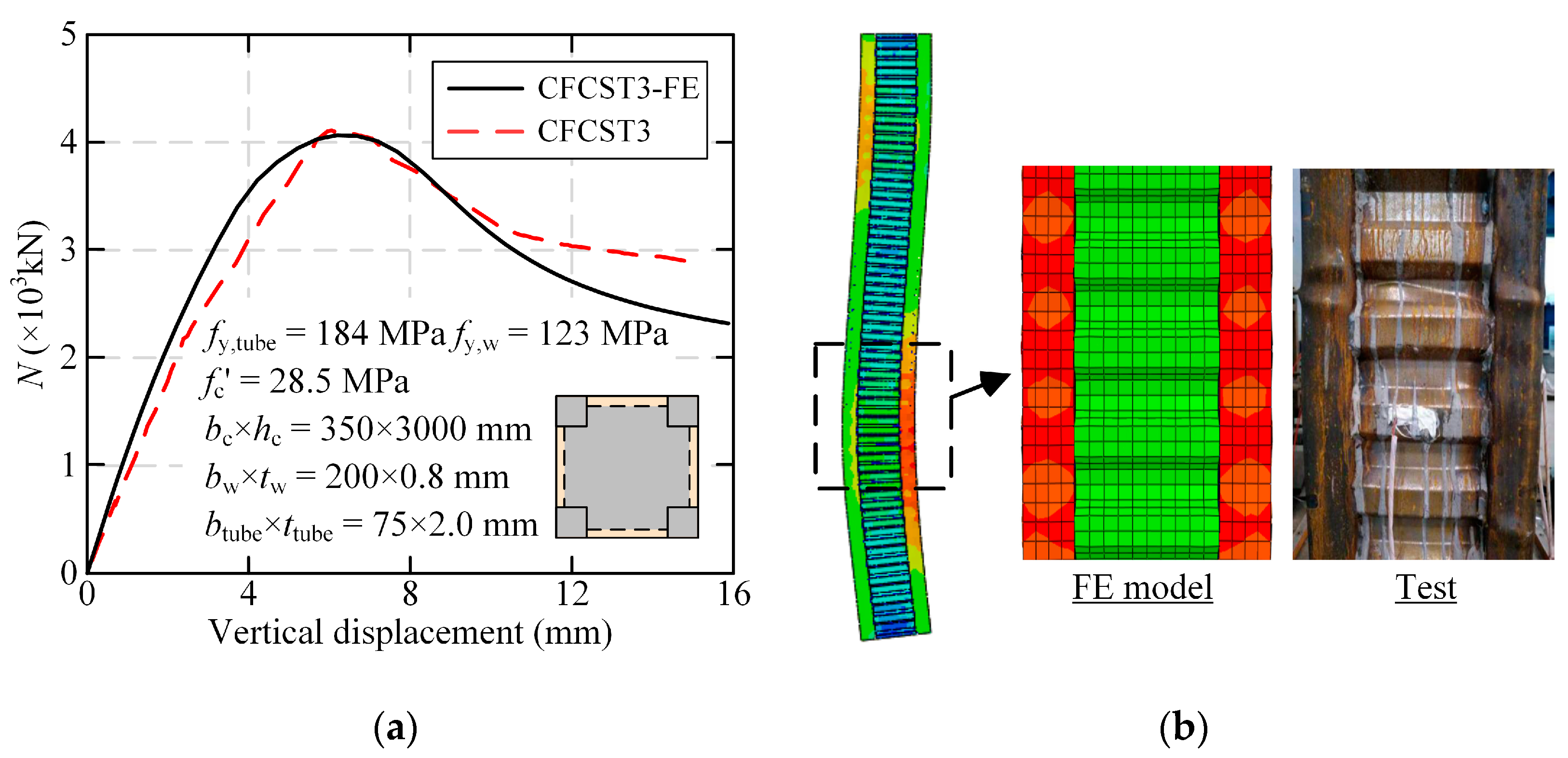
2.2. FE Model Validation

2.2.1. Sensitivity Analysis

A sensitivity analysis of mesh size was conducted, where a CFCST column with a width of 450 mm and a height of 9000 mm was taken as an example. The steel bar’s width was taken as 40 mm, and the corrugated steel plate’s thickness was set to 1.5 mm. As shown in Figure 4a, the load–displacement curves of the column with eccentricity ratios of 0.2 and 0.8 were plotted. When the mesh size of concrete and the corrugated steel plate varied from 25 mm to 100 mm, the load–displacement curves of the CFCST column under eccentric compression were almost the same. In addition, it was found from Figure 4b that the influence of the mesh size of steel bars had little effect on the simulation result when the mesh number per side of the steel bars was between 1 and 3. Therefore, a mesh size of 50 mm for concrete and the corrugate steel plate and a mesh number of 2 on each side of the steel bar were selected to balance calculation accuracy and efficiency.

2.2.2. Comparison Between FE Models and Tests

Because stability tests of CFCST columns under eccentric compression have not yet been carried out, a comparison was made between the FE results and the test results carried out by Tong et al. [35] and Kang et al. [46]. It was noted that Tong et al. [35] conducted tests on the sectional strength of CFCST columns, while Kang et al. [46] explored the stability behavior of CFCST columns with corner steel tubes. The schematic diagrams of the specimens are described in Figure 5. The load–displacement curves from both of the tests and the FE models are compared in Figure 6. It was found that the initial stiffness of the experimental and numerical curves was nearly identical, and the trend in the post-ultimate stage was close. The ultimate resistances obtained from the tests were 14,756 and 9343 kN, respectively, corresponding to the FE results of 14,679 and 9343 kN. Thus, the FE model proved to be reasonable to calculate the ultimate resistances of the CFCST columns. In addition, Figure 7 illustrates the comparison between the tests and the FE models of slender CFCST columns. The stability resistance of the test results was 4111 kN, while that of the numerical results was 4062 kN, with a difference of only −1.19%. The failure modes are further compared in Figure 7b. As the overall deformation in the test was not available in the literature, only the local buckling deformation was used for comparison. Both the tests and the simulations revealed the presence of bulges in the corner steel tubes.
In conclusion, the established FE model provided a reliable assessment of the sectional strength of the CFCST column and accurately simulated its stability performance. Thus, the FE model could be employed for further investigations of the stability performance of CFCST columns subjected to eccentric compression.

3. Numerical Results

As shown in Figure 2, both the square steel bars and the infilled concrete were modeled using eight-node solid elements (C3D8R), which offer high calculation accuracy with relatively low calculation costs. The corrugated steel plates were simulated using S4R elements. Welded connections between square steel bars and corrugated steel plates were modeled using tie constraints. The interactions between concrete and steel components were modeled using surface-to-surface contact. Hard contact was applied in the normal direction, so that the interaction force between steel and core concrete could be fully transmitted at the interface. In addition, the Coulomb friction model was used to describe the tangential behavior, and the friction coefficient was set as 0.6. The stability performance of CFCST columns under eccentric compression was explored using the validated FE model. As seen in Figure 8, the load–displacement curves with various eccentricities are presented, where a CFCST column with a cross-sectional width of 450 mm and a steel bar width of 40 mm was taken as an example. It was found that as the eccentricity increased, the axial resistance of the column exhibited a significant decrease. Specifically, when the eccentricity ratio increased from 0 to 1.0, the axial resistance decreased by 2646, 966, 592, 388, and 269 kN with each increment of 0.2, respectively. This suggested that the impact of eccentricity on the axial resistance of the column diminished as the eccentricity increased.
The axial resistance of the CFCST column was multiplied by the eccentricity to calculate the corresponding bending moment and, thus, the NM interaction curves of the column with different height-to-width ratios (hc/bc) are plotted in Figure 9. It was found that when the height-to-width ratio was small, the ultimate resistance of the column was controlled by the material strength, resulting in an outwardly convex shape of the NM interaction curve. The maximum bending moment reached 642 kN·m, which was 1.27 times the load-bearing capacity under pure bending. As hc/bc increased, the adverse influence of the second-order effect gradually increased, and the interaction curve became less convex. When the value of hc/bc was 30, the column experienced global buckling failure, and thus the interaction curve was close to a straight line. The load-bearing capacities of the column with various height-to-width ratios under pure axial compression and bending were further compared. It could be seen that hc/bc exhibited a negative effect on the axial resistance of the column, while it could hardly influence the pure bending resistance. Specifically, with the increase in the value of hc/bc from 10 to 30, the axial resistance dropped by 44% from 7421 kN to 4139 kN. However, the corresponding pure bending resistance varied from 505 to 502 kN·m, and the difference could be ignored.
The concrete stress under peak load was also investigated. The distribution of concrete vertical normal stress at mid-height of the column with different height-to-width ratios and eccentricities is described in Figure 10. It was observed that the concrete’s contribution to the ultimate resistance gradually decreased when the eccentricity increased. As shown in Figure 10a, the concrete was fully under compression when subject to axial compression. Due to the P-Δ effect, the stress distribution was asymmetrical. When the eccentricity ratio reached 1.0, only half of the concrete area remained under compression, and the maximum compressive normal stress decreased significantly. As the column was subjected to pure bending, the concrete contribution was negligible, as most of the concrete was in tension.
Moreover, the vertical normal stress of the concrete decreased gradually as the height-to-width ratio increased in the case of axial compression. This occurred because the CFCST column with a large value of hc/bc was prone to instability, resulting in a reduced load-bearing capacity of the column and a decrease in vertical normal stress. When the column height reached 13,500 mm, corresponding to hc/bc = 30, it was observed that the concrete’s vertical normal stress on one side was close to 0. As the eccentricity ratio increased, the influence of hc/bc on the stress distribution of concrete became less significant. In pure bending, the vertical normal stress distribution of concrete in the CFCST column with different values of hc/bc remained consistent.
The Mises stress distribution of steel at mid-height of the CFCST column is shown in Figure 11. Under the condition of axial compression, two of the four steel bars reached yield stress, while the other two did not yield due to the second-order effect. Moreover, the Mises stress of steel bars decreased as the height-to-width ratio of the column increased. However, when subjected to eccentric compression and when the eccentricity ratio was 0.5, the tensile stress caused by the bending moment was much greater than that caused by axial compression. Thus, two of the four steel bars yielded under compression, while the other two yielded under tension. For corrugated steel plates, when the eccentricity and the height-to-width ratio were both small, the confinement effect of the corrugated steel plate could develop, resulting in relatively high horizontal stress. In other cases, stress in the corrugated steel plate was much lesser compared to that in the steel bars. Similarly to concrete’s distribution, the steel stress exhibited little difference for columns with various height-to-width ratios under pure bending.

4. Parametric Analysis

To explore the impact of key parameters, parametric analysis was conducted. According to the previous study [37], the commonly used column width in practice was within 350–500 mm, and the steel bar’s width was not greater than 1/10 of the column’s width. Due to the high out-of-plane bending stiffness of the corrugated steel plate, the width-to-thickness ratio could be greater than 250 [36]. Therefore, the details of FE examples are tabulated in Table 1. Groups 1 and 2 were used to explore the influence of CFCST column width and steel bar width, respectively. Groups 3 and 4 were designed to investigate the effect of corrugation dimensions, including corrugation amplitude and the thickness of corrugated steel plates. Furthermore. the influence of material strengths were studied using groups 5 and 6. For each group of FE models, the eccentricity ratio ec/bc varied from 0 to 2.0, and the pure bending condition were also considered.

4.1. Effect of Widths of Columns and Steel Bars

The effect of column width (bc) is presented in Figure 12. It was observed that the influence of column width on the axial resistance was less significant with the increase in the eccentricity ratio. As show in Figure 12a, when the column width increased from 400 to 500 mm, the axial resistance was increased by 34.2% from 5178 to 6950 kN under axial compression, while the increment was reduced by 9.7% with an eccentricity ratio of 1.0. To further analyze the stability performance of the CFCST column, a normalized N–M interaction curve (N/Nu0-M/Mu0) was proposed, where the peak axial loads were divided by the sectional strength under pure axial compression and the corresponding bending moments were divided by the flexural resistance under pure bending. It should be noted that the area enclosed by the normalized N–M interaction curve and both axes could reflect the stability performance of the column. As described in Figure 12b, when the value of hc/bc was 10, the enclosed area increased significantly as the column width increased. This indicated that increasing the column width could effectively improve the stability performance of the CFCST column with a small height-to-width ratio under eccentric compression. When the value of hc/bc increased, the enclosed area was reduced significantly, and the influence of column width gradually decreased. As the value of hc/bc increased to 30, the normalized N–M interaction curves with different column widths basically coincided, suggesting that the column width could not affect the stability behavior of the column with a large value of hc/bc.
The influence of the steel bar’s width on the CFCST column is illustrated in Figure 13. Different from the effect of column width, the effect of steel bar width was increasingly significant as the eccentricity ratio increased. As the column was subjected to axial compression, the peak axial load was enhanced from 6010 to 7204 kN when the steel bar width increased from 40 to 50 mm. However, the peak axial load could be increased by 43% with an eccentricity ratio of 1.0. Therefore, when the CFCST column mainly experiences small eccentricity ratios, increasing the column’s width is a more economical way to enhance its bearing capacity. However, for high eccentricity ratios, increasing the steel bar’s width is more appropriate. In addition, when the value of hc/bc was relatively large (e.g., hc/bc = 20), the normalized interaction curve of the column was hardly affected by the steel bar’s width.

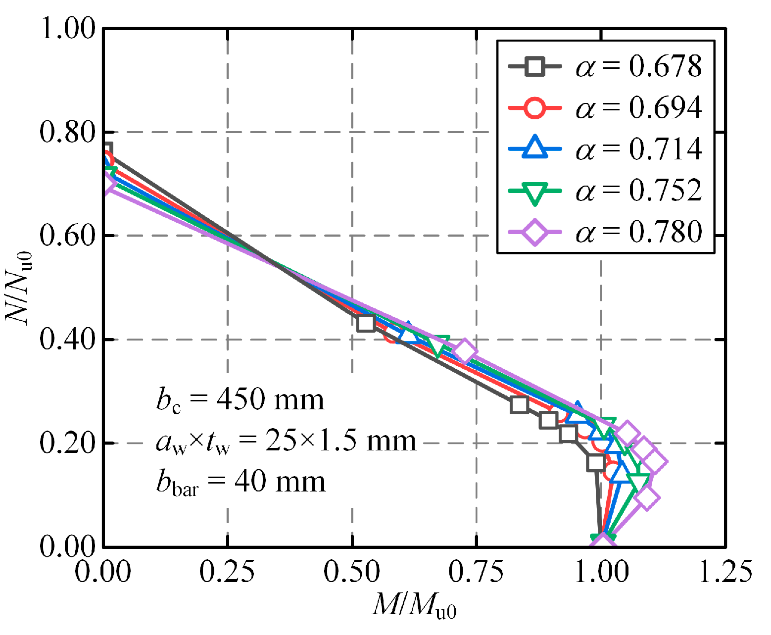
4.2. Effect of Corrugation Dimensions

The effects of corrugation amplitude on the performance of CFCST columns are plotted in Figure 14. As shown in Figure 14a, increasing the corrugation amplitude resulted in a reduction of load-bearing capacities, although the effect was not significant. Moreover, its impact on pure axial compressive resistance was greater than its impact on pure flexural resistance. This was because the cross-sectional area of concrete was reduced due to the increase in corrugation amplitude. For the column under pure axial compression, the concrete was mostly under compression, and the axial resistance was negatively correlated with corrugation amplitude. However, as the concrete was almost unstressed under pure bending conditions, corrugation amplitude had little influence on the pure bending resistance of the CFCST column. As plotted in Figure 14b, the influence of corrugation amplitude could be ignored when the N–M interaction curve was normalized.
The impact of corrugated steel plate thickness is expressed in Figure 15. It was concluded from Figure 15 that increasing the steel plate’s thickness enhanced the load-bearing capacity of the column when the height-to-depth ratio was small, but it had little effect when the ratio was large. Due to the accordion effect, it is well-known that the corrugated steel plate does not carry vertical loads [47,48], which enhances the load-bearing capacity of the column by constraining the infilled concrete. However, when the value of hc/bc was large, the confinement effect could not be fully developed. As a result, the impact of the corrugated steel plate’s thickness could be ignored. Thus, it is not recommended to use thick corrugated steel plates in engineering practice for economic design.

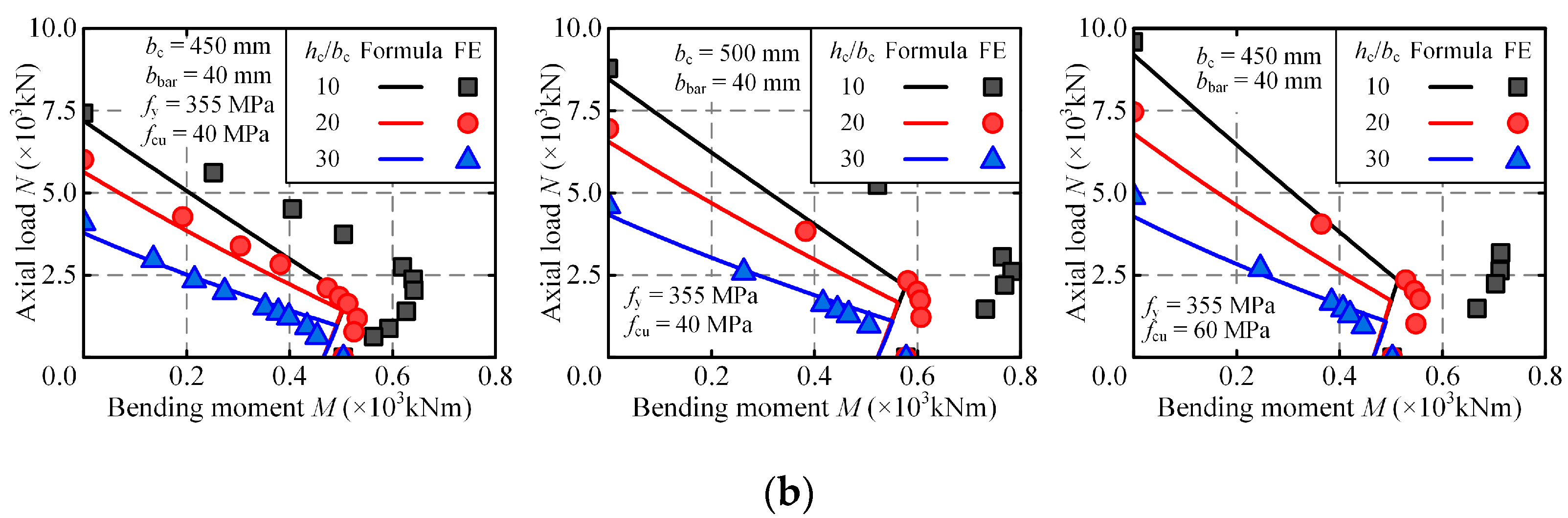
4.3. Effect of Material Strengths

The influence of steel bar strength is shown in Figure 16a. It was concluded from Figure 16 that improving the steel bars’ strength enhanced the resistance of the CFCST column, and the effect became more significant as the eccentricity ratio increased. As shown in Table 2, the axial resistance was increased by 10.5% from 6010 to 6642 kN when the column with a value of hc/bc = 20 was under pure axial compression, while the enhancement was 22.4% with an eccentricity ratio of 1.0. In addition, for the column with a large value of hc/bc, increasing the steel bar’s strength had little effect on the load-bearing capacity when the eccentricity ratio was small. Specifically, the pure axial resistance was only increased by 4.2% from 4139 to 4312 kN for the CFCST column with a value of hc/bc = 30. As plotted in Figure 16b, the concrete’s strength had a positive effect on the load-bearing capacity of the column. The influence of concrete strength gradually weakened with the increase in the eccentricity ratio, which was different from the impact of the steel bar’s strength. As shown in Table 2, when the eccentricity ratio increased from 0 to 0.2, 0.4, 0.6, 0.8, and 1.0, the improvement in the ultimate resistance caused by the increase in concrete strength decreased from 24.2% to 19.8%, 14.2%, 9.8%, 7.5%, and 6.1%, respectively. When subjected to pure bending, the bending resistance was only increased by 1%, from 503 to 508 kN·m. As a result, it is suggested to improve the stability resistance of the CFCST column with a large eccentricity ratio by increasing the steel’s strength and to improve its stability at a small eccentricity ratio by increasing the concrete’s strength.
To further investigate the effect of material strength, the concrete bearing coefficient (αc) was introduced, which can be calculated as
α c = N y , c N y = 1 + ξ A c , min f c 1 + ξ A c , min f c + A s , bar f y , bar
in which Ny and Ny,c are the sectional resistance and the vertical load borne by concrete of the CFCST column under axial compression [35]. Thus, the concrete bearing coefficient reflected the load contribution of concrete in stub columns.
The normalized interaction curves of the CFCST column with a value of hc/bc = 20 are depicted in Figure 17. It could be found that the ratio of the maximum bending moment to the pure bending resistance increased gradually with the increase in the concrete bearing coefficient, resulting in an increase in the area enclosed by the normalized interaction curve and the coordinate axes. Therefore, the steel bar’s strength exhibited a negative impact on the stability performance of the CFCST column under eccentric compression, while the strength of concrete had a beneficial influence.

5. Design Curves of CFCST Columns

For practical engineering applications, it is crucial to propose NM stability interaction curves. However, corresponding design codes for CFCST column have not been proposed. Because the CFCST column is a new type of CFST column, the design formulae for composite columns subjected to combined axial compression and bending specified in AISC 360 [49] and GB 50936 [50] were used to estimate the stability resistance of the CFCST column.
According to the American code AISC 360 [49], the NM interaction curves for composite columns varied according to the width-to-thickness ratios of the steel plates to consider the effect of local buckling. Because the corrugated steel plates do not directly carry vertical loads, the sections of CFCST columns can be divided into compact sections. Therefore, the NM interaction curves of the column are expressed through a piecewise function, as follows:
N N c + 8 9 M M c 1 N N c 0.2 N 2 N c + M M c 1 N N c < 0.2
in which Nc and Mc are the load-bearing capacity of the column under pure axial compression and bending, respectively. It should be noted that Equation (9) can be used to calculate both the strength and stability resistance of the composite column. When predicting the stability resistance of the column, the influence of the global stability of the column under axial compression should be considered, while the bending moment M applied to the column should be divided by (1 − N/Ncr) to account for the second-order effect. Thus, Equation (9) can be expressed as
N φ N u + 8 9 M 1 N / N cr 1 M u 1 N φ N u 0.2 N 2 φ N u + M 1 N / N cr 1 M u 1 N φ N u < 0.2
in which Nu and Mu are the cross-sectional resistance of the column under axial compression and pure bending, which can be calculated using Equations (11) [35] and (12) [38], respectively; φ is the stability coefficient of the column under axial compression, calculated through Equation (13) based on previous studies [37]; and Ncr1 is the elastic buckling load of the column, where the disadvantage of concrete cracks should be considered when calculating the flexural stiffness, as shown in Equations (14) and (15).
N u = A s , bar f y , bar + 1 + ξ A c , min f c
M u = 2 b bar 2 f y b c b bar
φ = Φ Φ 2 4 λ n 2 2 λ n 2 ,   Φ = 1 . 32 λ n 2 + 0 . 15 λ n + 1
N cr 1 = π 2 E s I s , bar + C 1 E c I c h c 2
C 1 = 0.25 + 3 A s , bar A s , bar + A c , min 0.75
in which As,bar and fs,bar are the cross-sectional area and yield strength of steel bars, respectively; Ac,min is the minimum cross-sectional area of concrete; Is,bar is the moment of inertia of steel bars; and Ic is the moment of inertia of concrete, which was calculated based on the minimum section.
Similarly to AISC 360, a piecewise function was also used in the Chinese code GB 50936 to calculate the stability resistance of the composite column under eccentric compression, as shown in Equation (16).
N φ N u + M 1 . 5 1 0.4 N / N cr 2 M u 1 N φ N u 0.255 N 2.17 φ N u + M 1 0.4 N / N cr 2 M u 1 N φ N u < 0.255
in which Ncr2 is the elastic buckling load of the CFCST column without considering the influence of concrete cracking.
The results calculated according to the design formulae specified in the codes are compared with the numerical results, as described in Figure 18. It was observed that the theoretical results obtained from AISC 360 were over-conservative, especially when the value of hc/bc was small. The maximum error between formulae and simulations reached 74% at the value of hc/bc = 10. Although the error gradually reduced with the increase of hc/bc, the maximum error still reached 29% when the value of hc/bc was 30. In contrast, the calculation results based on GB 50936 exhibited smaller deviations from numerical simulation results. When the value of hc/bc was less than 20, the design formula exhibited a safe prediction, with a maximum error of 41%. However, as the value of hc/bc increased to 30, the calculation result tended to overestimate the load-bearing capacity of the column, leading to unsafe results. Therefore, the design formulae specified in AISC 360 and GB 50936 were unsuitable to estimate the resistance of CFCST columns under eccentric compression.
In order to obtain calculation results with higher accuracy, the following formula was obtained by fitting the numerical results combined with the previous study [51].
N φ N u + 1 α c 1 + 2.25 N / N cr M 1 φ N / N cr M u 1 N N u α c N φ N u + 1 α c 1 + 2.25 N / N cr M 1 α c + γ N / N cr M u 1 N N u < α c γ = α c + 1 / λ n 2 N / N u φ
The comparison results between FE models and the proposed design curves are depicted in Figure 19, where the CFCST column with a value of hc/bc = 20 was taken as an example. The results indicated that the proposed design formula could predict the load-bearing capacity of CFCST columns conservatively. The errors between the results obtained from FE models and the proposed formula are described in Figure 20. Among the numerical examples involved in this paper, the simulation results of most examples were larger than the prediction results of the design formula, and only 4.4% of the examples exhibited a smaller simulation result. The minimum ratio of FE results to calculation results was 0.97. Additionally, when the column was under large eccentric compression, the calculation results tended to be more conservative. This was partly because the contribution of corrugated steel plates was ignored when calculating the pure bending resistance of the column, leading to a small theoretical result of Mu. However, the error between the FE and formula results was generally within 15%, with an average ratio between them of 1.089 and a coefficient of variation of 0.043. Further analysis revealed that the proposed formula demonstrated a significant improvement in accuracy compared to AISC 360. When compared to the Chinese code GB 50936, the proposed formula was more accurate, with a small value of hc/bc (e.g., hc/bc = 10), while GB 50936 performed better, with a large value of hc/bc (e.g., hc/bc = 30). Because GB 50936 tended to overestimate the load-bearing capacity at higher values of hc/bc, the proposed formula was more suitable overall. As a result, the proposed design formula exhibited higher prediction accuracy compared to existing codes within the range of parameters discussed in this paper, which could be used in practical engineering applications.

6. Conclusions

In this paper, the global buckling performance of a novel concrete-filled corrugated steel tubular (CFCST) column under eccentric compression was investigated through numerical simulation. The main conclusions were drawn as follows:
  • The finite element (FE) model was built and validated through existing test results, demonstrating that the FE model could be used in analyzing the stability performance of the CFCST column.
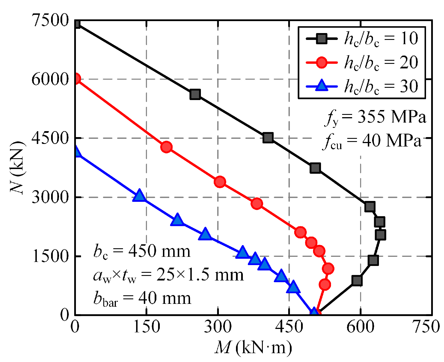
  • The NM interaction curve was convex at small height-to-width ratios, which was close to a straight line as the ratio increased. Numerical analysis indicated that the contribution of concrete to the load-bearing capacity of the CFCST column decreased with the increasing eccentricity ratio.
  • Parametric analysis indicated that increasing the column width and the concrete strength was more economical for enhancing the stability resistance of the column with small eccentricity ratios, while increasing the steel strength and the steel bar width was recommended for large eccentricity ratios. Additionally, the effects of corrugation amplitude and corrugated steel plate thickness on stability resistance were relatively small.
  • Based on the FE results, a design formula to predict the stability resistance of the CFCST column under eccentric compression was proposed with acceptable accuracy and safety, which could be used for practical engineering applications.
For further study, the stability performance of the rectangular CFCST column under eccentric compression should be explored, as it may exhibit different behavior and offer more design flexibility in practical applications compared to square columns. Furthermore, it is essential to investigate the behavior of CFCST columns subjected to combined axial compression and biaxial bending, which are commonly encountered in engineering structures, especially for the columns arranged at the corner. These studies will help us to have a more comprehensive understanding of CFCST columns and provide guidance for their practical engineering applications.

Author Contributions

Conceptualization, C.-Q.Y., S.-J.D. and J.-Z.T.; methodology, J.-Z.T.; software, C.-Q.Y. and S.-J.D.; validation, S.-J.D.; formal analysis, J.-Z.T.; investigation, C.-Q.Y.; resources, C.-Q.Y.; data curation, C.-Q.Y.; writing—original draft preparation, C.-Q.Y. and S.-J.D.; writing—review and editing, C.-Q.Y., S.-J.D. and J.-Z.T.; visualization, C.-Q.Y. and S.-J.D.; supervision, J.-Z.T. All authors have read and agreed to the published version of the manuscript.

Funding

This research was funded by Natural Science Foundation of Zhejiang Province, grant number LR24E080002, and National Natural Science Foundation of China, grant number 52478219.

Data Availability Statement

All data are available upon request by contacting the corresponding author.

Conflicts of Interest

The authors declare no conflicts of interest.

References

  1. Yu, C.Q.; Tong, J.Z.; Zhou, S.M.; Zhang, J.M.; Shen, J.J.; Zhang, L.; Tong, G.S.; Li, Q.H.; Xu, S.L. State-of-the-art review on steel-concrete composite walls. Sustain. Struct. 2024, 4, 000035. [Google Scholar] [CrossRef]
  2. Chen, Y.L.; Tong, J.Z.; Li, Q.H.; Xu, S.L.; Shen, L.M. Application of high-performance cementitious composites in steel–concrete composite bridge deck systems: A review. J. Intell. Constr. 2024, 2, 9180012. [Google Scholar] [CrossRef]
  3. Varma, A.H.; Malushte, S.R.; Sener, K.C.; Lai, Z.C. Steel-plate composite (SC) walls for safety related nuclear facilities: Design for in-plane forces and out-of-plane moments. Nucl. Eng. Des. 2014, 269, 240–249. [Google Scholar] [CrossRef]
  4. Li, P.P.; Jiang, J.F.; Li, Q.; Ren, Z.G. Axial compression performance and optimum design of round-cornered square CFST with high-strength materials. J. Build. Eng. 2023, 68, 106145. [Google Scholar] [CrossRef]
  5. Yang, S.L.; Zhang, L.; Zhang, J.W.; Fu, B.; Tong, G.S.; Jing, T. Seismic behavior of concrete-filled wide rectangular steel tubular (CFWRST) stub columns. J. Constr. Steel Res. 2022, 196, 107402. [Google Scholar] [CrossRef]
  6. Yang, Y.L.; Wang, G.J.; Yang, W.Q.; Wei, X.; Chen, Y.F. Experimental research on fire behavior of L-shaped CFST columns under axial compression. J. Constr. Steel Res. 2022, 198, 107505. [Google Scholar] [CrossRef]
  7. Wang, E.; Ding, F.X.; Wang, L.P.; Chen, Y.B.; Sheng, S.J.; Shen, J.T.; Lin, Q.T. Analytical study on the composite behavior of rectangular CFST columns under combined compression and torsion. Case Stud. Constr. Mater. 2022, 16, e01074. [Google Scholar] [CrossRef]
  8. Furlong, R.W. Strength of steel-encased concrete beam columns. J. Struct. Div. 1967, 93, 113–124. [Google Scholar] [CrossRef]
  9. Han, L.H.; Li, W.; Bjorhovde, R. Developments and advanced applications of concrete-filled steel tubular (CFST) structures: Members. J. Constr. Steel Res. 2014, 100, 211–228. [Google Scholar] [CrossRef]
  10. Li, W.J.; Li, W. Performance of spirally reinforced high-strength circular CFST column under eccentric compression. J. Constr. Steel Res. 2024, 216, 108576. [Google Scholar] [CrossRef]
  11. Medall, D.; Ibáñez, C.; Espinós, A.; Romero, M.L. Experimental and numerical study of high-strength materials on slender steel-reinforced CFST columns in fire. Thin Walled Struct. 2025, 209, 112904. [Google Scholar] [CrossRef]
  12. Zhang, W.H.; Wang, R.; Zhao, H.; Lam, D.; Chen, P. Axial-load response of CFST stub columns with external stainless steel and recycled aggregate concrete: Testing, mechanism analysis and design. Eng. Struct. 2022, 256, 113968. [Google Scholar] [CrossRef]
  13. Chen, M.H.; Yan, J.B. Compression behaviours of CFSTs using stainless-steel tubes at low temperatures. J. Constr. Steel Res. 2023, 211, 108120. [Google Scholar] [CrossRef]
  14. Zhi, D.; Xia, P.; Wang, S.Q.; Gong, F.Y.; Cao, W.L.; Wang, D.M.; Ueda, T. RBSM-based mesoscale study of mechanical properties and frost damage behaviors for recycled fine aggregate concrete. Constr. Build. Mater. 2024, 416, 135136. [Google Scholar] [CrossRef]
  15. Wang, S.Q.; Xia, P.; Gong, F.Y.; Zeng, Q.; Chen, K.Y.; Zhao, Y.X. Multi objective optimization of recycled aggregate concrete based on explainable machine learning. J. Clean. Prod. 2024, 445, 141045. [Google Scholar] [CrossRef]
  16. Yang, Z.M.; Chen, J.; Wang, J.; Zeng, C.Q. Axial compressive behavior of FRP-confined square CFST columns reinforced with internal latticed steel angles for marine structures. Eng. Struct. 2024, 319, 118847. [Google Scholar] [CrossRef]
  17. Zeng, J.J.; Zheng, Y.W.; Liu, F.; Guo, Y.C.; Hou, C. Behavior of FRP Ring-Confined CFST columns under axial compression. Compos. Struct. 2021, 257, 113166. [Google Scholar] [CrossRef]
  18. Uy, B. Local and postlocal buckling of fabricated steel and composite cross sections. J. Struct. Eng. 2001, 127, 666–677. [Google Scholar] [CrossRef]
  19. Liang, Q.Q.; Uy, B.; Richard Liew, J.Y. Nonlinear analysis of concrete-filled thin-walled steel box columns with local buckling effects. J. Constr. Steel Res. 2006, 62, 581–591. [Google Scholar] [CrossRef]
  20. Liang, Q.Q.; Uy, B.; Richard Liew, J.Y. Local buckling of steel plates in concrete-filled thin-walled steel tubular beam–columns. J. Constr. Steel Res. 2007, 63, 396–405. [Google Scholar] [CrossRef]
  21. Long, Y.L.; Zeng, L.; Gardner, L.; Wadee, M.A. A new model for calculating the elastic local buckling stress of steel plates in square CFST columns. Thin Walled Struct. 2022, 171, 108756. [Google Scholar] [CrossRef]
  22. Li, J.W.; Jia, C.; Gao, S.; Guo, L.H. Experimental and numerical study on axial compression behavior of slender CFST columns with localized pitting corrosion damage. Constr. Build. Mater. 2024, 414, 134858. [Google Scholar] [CrossRef]
  23. Zhang, L.; Mao, C.X.; Li, X.G.; Tong, G.S.; Jing, T.; Wang, Y.C. Experimental study on CFNRST members under combined compression and bending. J. Constr. Steel Res. 2020, 167, 105950. [Google Scholar] [CrossRef]
  24. Yan, Y.H.; Liang, H.J.; Lu, Y.Y.; Zhao, X.B. Slender CFST columns strengthened with textile-reinforced engineered cementitious composites under axial compression. Eng. Struct. 2021, 241, 112483. [Google Scholar] [CrossRef]
  25. Tong, J.Z.; Wu, R.M.; Wang, L.Q. Experimental and numerical investigations on seismic behavior of stiffened corrugated steel plate shear walls. Earthq. Eng. Struct. Dyn. 2023, 52, 3551–3574. [Google Scholar] [CrossRef]
  26. Xie, C.; Dou, C.; Ru, Y. Cyclic test and lateral resistant design of corrugated plate shear walls. Structures 2023, 49, 748–764. [Google Scholar] [CrossRef]
  27. Jiang, Z.Q.; Niu, Z.Y.; Zhang, A.L.; Liu, X.C. Design method of axial compression stability for cross-section corrugated plate steel special-shaped column. Thin Walled Struct. 2024, 194, 111243. [Google Scholar] [CrossRef]
  28. Tong, J.Z.; Zhang, J.M.; Yu, C.Q.; Tong, G.S.; Li, Q.H.; Xu, S.L. Seismic experiments and shear resistance prediction of multi-celled corrugated-plate CFST walls. Earthq. Eng. Struct. Dyn. 2024, 53, 1681–1704. [Google Scholar] [CrossRef]
  29. Fang, Y.; Yang, H.; Lu, B.; Wang, Y.Y.; Dong, J.C. Experimental investigation on shear-bending performances of concrete-filled thin-walled corrugated steel tubes. Eng. Struct. 2023, 274, 115147. [Google Scholar] [CrossRef]
  30. Fang, Y.; Wang, Y.Y.; Elchalakani, M.; Yang, H. Experimental investigation on concrete-filled corrugated steel tubular column under constant axial load and cyclic load. Eng. Struct. 2021, 248, 113245. [Google Scholar] [CrossRef]
  31. Yang, L.G.; Wang, Y.Y.; Liew, J.Y.R. Compression-bending strength model for corrugated steel tube confined reinforced concrete section. J. Struct. Eng. 2021, 147, 04021187. [Google Scholar] [CrossRef]
  32. Wang, Y.Y.; Yang, L.G.; Yang, H.; Liu, C.Y. Behaviour of concrete-filled corrugated steel tubes under axial compression. Eng. Struct. 2019, 183, 475–495. [Google Scholar] [CrossRef]
  33. Zou, Y.; Wang, L.; Sun, Z.X.; Pan, J.; Chen, M.; Wu, Y.C. Experimental and numerical studies of concrete-filled corrugated steel tubular column under axial compression. Eng. Struct. 2023, 276, 114813. [Google Scholar] [CrossRef]
  34. Sun, Z.X.; Zou, Y.; Wang, C.Q.; Pan, J.; Wang, L.; Chen, M. Study on confinement mechanism of core concrete in steel tubular-corrugated steel plate confined concrete columns. J. Build. Eng. 2022, 52, 104497. [Google Scholar] [CrossRef]
  35. Tong, J.Z.; Zhang, J.M.; Yu, C.Q.; Wu, R.M.; Tong, G.S.; Chen, M.; Gao, W. Experimental study on axial compressive behavior of concrete-filled corrugated steel tubular columns. Eng. Struct. 2024, 313, 118267. [Google Scholar] [CrossRef]
  36. Liao, X.; Li, X.; Zhao, S.D.; Yang, C.; Yin, D.D. Behavior of eccentrically loaded rectangular CFST components for shear walls using double horizontally-corrugated steel plates. Eng. Struct. 2024, 303, 117470. [Google Scholar] [CrossRef]
  37. Li, Y.D.; Yu, C.Q.; Zhu, H.C.; Tong, J.Z.; Tong, G.S.; Xiao, Z.B. Global stability design of concrete-filled corrugated steel tubular columns. Structures 2024, 62, 106149. [Google Scholar] [CrossRef]
  38. Yu, C.Q.; Tong, G.S.; Duan, S.J.; Chen, M.; Tong, J.Z. Combined axial and flexural behavior of concrete-filled corrugated steel tubular columns. J. Constr. Steel Res. 2024, 221, 108912. [Google Scholar] [CrossRef]
  39. Abaqus. Abaqus User’s Manual, Version 6.14; Dassault Systemes Simulia Corp.: Paris, France, 2014. [Google Scholar]
  40. Han, L.H.; Yao, G.H.; Tao, Z. Performance of concrete-filled thin-walled steel tubes under pure torsion. Thin Walled Struct. 2007, 45, 24–36. [Google Scholar] [CrossRef]
  41. Huang, Y.; Li, W.J.; Lu, Y.Y.; Liang, H.J.; Yan, Y.H. Behaviour of CFST slender columns strengthened with steel tube and sandwiched concrete jackets under axial loading. J. Build. Eng. 2022, 45, 103613. [Google Scholar] [CrossRef]
  42. Tao, Z.; Wang, Z.B.; Yu, Q. Finite element modelling of concrete-filled steel stub columns under axial compression. J. Constr. Steel Res. 2013, 89, 121–131. [Google Scholar] [CrossRef]
  43. ACI 318-19; Building Code Requirements for Structural Concrete (ACI 318-19) and Commentary (ACI 318R-19). American Concrete Institute: Farmington Hills, MI, USA, 2019.
  44. GB50010-2010; Code for Design of Concrete Structures. China Architecture & Building Press: Beijing, China, 2015. (In Chinese)
  45. Shen, J.; Wang, C.; Jiang, J. Finite Element Method of Reinforced Concrete and Limit Analysis of Plates and Shells; Tsinghua University Press: Beijing, China, 1993. [Google Scholar]
  46. Kang, J.X.; Zou, Y.; Wang, C.Q.; Wu, Y.C.; Chen, M. Study on behavior of corrugated plate-square concrete filled steel tubular columns under axial compression. J. Build. Struct. 2020, 41, 146–153. (In Chinese) [Google Scholar]
  47. Dou, C.; Xie, C.; Wang, Y.; Yang, N. Cyclic loading test and lateral resistant behavior of flat-corrugated steel plate shear walls. J. Build. Eng. 2023, 66, 105831. [Google Scholar] [CrossRef]
  48. Dou, C.; Ru, Y.; Jiang, Z.Q.; Wang, Y. Lateral resistant behavior of grid-reinforced steel corrugated shear walls. J. Struct. Eng. 2024, 150, 04024047. [Google Scholar] [CrossRef]
  49. AISC 360-16; Specification for Structural Steel Buildings. American Institute of Steel Construction: Chicago, IL, USA, 2016.
  50. GB 50936; Technical Code for Concrete Filled Steel Tubular Structures. China Architecture & Building Press: Beijing, China, 2014. (In Chinese)
  51. Tong, G.S. Design Method of Steel Structure and Steel-Concrete Composite Structure; China Architecture & Building Press: Beijing, China, 2022. [Google Scholar]
Figure 1. Diagram of CFCST columns.
Modelling 06 00022 g001
Figure 2. Description of FE model. (a) FE models. (b) First-order buckling mode.
Modelling 06 00022 g002
Figure 3. Cross-sectional area of concrete.
Modelling 06 00022 g003
Figure 4. Sensitivity analysis of mesh size. (a) Mesh size of concrete and corrugated steel plate. (b) Mesh size of steel bar.
Modelling 06 00022 g004
Figure 5. Schematic diagrams of specimens. (a) Specimens tested by Tong et al. [35]. (b) Specimens tested by Kang et al. [46].
Modelling 06 00022 g005
Figure 6. Load–displacement curves of stub CFCST columns. (a) CFCST1. (b) CFCST2.
Modelling 06 00022 g006
Figure 7. Comparison results of slender CFCST columns. (a) Load–displacement curves. (b) Failure modes.
Modelling 06 00022 g007
Figure 8. Load–displacement curves of CFCST columns with different eccentricities.
Modelling 06 00022 g008
Figure 9. NM interaction curves of CFCST columns.
Modelling 06 00022 g009
Figure 10. Stress distribution of concrete. (a) hw = 4500 mm; (b) hw = 9000 mm; (c) hw = 13,500 mm.
Modelling 06 00022 g010
Figure 11. Stress distribution of steel. (a) hw = 4500 mm; (b) hw = 9000 mm; (c) hw = 13,500 mm.
Modelling 06 00022 g011
Figure 12. Effect of column width. (a) N–M interaction curves. (b) Normalized N–M interaction curves.
Modelling 06 00022 g012
Figure 13. Effect of steel bar width. (a) NM interaction curves. (b) Normalized NM interaction curves.
Modelling 06 00022 g013
Figure 14. Effect of corrugation amplitude. (a) NM interaction curves. (b) Normalized NM interaction curves.
Modelling 06 00022 g014
Figure 15. Effect of corrugated steel plate thickness. (a) NM interaction curves. (b) Normalized NM interaction curves.
Modelling 06 00022 g015
Figure 16. Effect of material strengths. (a) Steel’s strength. (b) Concrete’s strength.
Modelling 06 00022 g016
Figure 17. Effect of concrete bearing coefficient.
Modelling 06 00022 g017
Figure 18. Comparison between design codes and FE results. (a) AISC 360; (b) GB 50936.
Modelling 06 00022 g018aModelling 06 00022 g018b
Figure 19. Comparison results of the proposed formula and numerical results.
Modelling 06 00022 g019
Figure 20. Accuracy of proposed N–M interaction curves.
Modelling 06 00022 g020
Table 1. Details of FE examples.
GroupCross-Sectional
Dimensions (mm)
Height-to-Width
Ratio
Corrugation
Dimensions (mm)
Material Strength
(MPa)
bcbbarhc/bcawtwfy,wfy,barfcu
Group 1400–5004010, 20, 30251.535535540
Group 245040–5010, 20, 30251.535535540
Group 34505010, 20, 3015–351.535535540
Group 44504010, 20, 30251.5–2.535535540
Group 54504010, 20, 30251.5355235–46040
Group 64504010, 20, 30251.535535540–60
Table 2. Ultimate resistance of CFCST column with different eccentricity ratios (unit: kN).
Material StrengthEccentricity Ratio
00.20.40.60.81.0
fy,bar = 355 Mpa, fcu = 40 MPa601033842431183914321152
fy,bar = 420 Mpa, fcu = 40 MPa664237602689206816851410
fy,bar = 355 Mpa, fcu = 60 MPa746240532777202015401222
Disclaimer/Publisher’s Note: The statements, opinions and data contained in all publications are solely those of the individual author(s) and contributor(s) and not of MDPI and/or the editor(s). MDPI and/or the editor(s) disclaim responsibility for any injury to people or property resulting from any ideas, methods, instructions or products referred to in the content.

