Article

Finite-Element Based Image Registration for Endovascular Aortic Aneurysm Repair

by
Aymeric Pionteck
1,2,
Baptiste Pierrat
1,
Sébastien Gorges
2,
Jean-Noël Albertini
3 and
Stéphane Avril
1,*
1
Mines Saint-Etienne, Univ Lyon, Univ Jean Monnet, INSERM, U1059 Sainbiose, Centre CIS, F-42023 Saint-Etienne, France
2
THALES, Microwave & Imaging Sub-Systems, 38430 Moirans, France
3
INSERM, U1059 Sainbiose and University Hospital of Saint-Etienne, Univ Jean Monnet, F-42000 Saint-Etienne, France
*
Author to whom correspondence should be addressed.
Modelling 2020, 1(1), 22-38; https://doi.org/10.3390/modelling1010002
Submission received: 29 May 2020 / Revised: 4 July 2020 / Accepted: 8 July 2020 / Published: 11 July 2020
(This article belongs to the Section Modelling in Biology and Medicine)

Abstract

:
In this paper we introduce a new method for the registration between preoperative and intraoperative computerized tomography (CT) images used in endovascular interventions for aortic aneurysm repair. The method relies on a 3D finite-element model (FEM) of the aortic centerline reconstructed from preoperative CT scans. Intraoperative 2D fluoroscopic images are used to deform the 3D FEM and align it onto the current aortic geometry. The method was evaluated on clinical datasets for which a reference CT scan was available to evaluate the registration errors made by our method and to compare them with other registration methods based on rigid transformations. Errors were estimated based on the predicted locations of landmarks positioned at different branch ostia. It appeared that our method always reduced the registration errors of at least 20% compared to gold standard 3D rigid registration and permitted to reach a global precision of 3.8 mm and a renal precision of 2.6 mm, which is a significant improvement compatible with surgical specifications. Finally, the major asset of our method is that it only requires one fluoroscopic intraoperative 2D image to perform the 3D non-rigid registration. This would reduce patient irradiation and cut the costs compared to traditional methods.

1. Introduction

Cardiovascular diseases are one of the first causes of death in industrialized countries, with 45,000 cases per year in the United States related to abdominal aortic aneurysms (AAA) [1]. Minimally invasive procedures known as Endovascular Aneurysm Repair (EVAR) procedures are particularly well adapted to the treatment of AAA and are conducted daily in modern hospitals. Stent-grafts are inserted through the femoral artery and are deployed using assistance of 2D angiography and fluoroscopy. The intraoperative mortality of EVAR is lower (1.5%) than open surgical repair (4.6%) [2]. However, the aneurysm-related mortality in the long term is similar [3,4]. Sophisticated fenestrated stent grafts have to be used to repair AAA expanding beyond ostia of renal arteries. In that case, the stent-graft should be positioned as precisely as possible, with an error less than 3 mm [5], to facilitate catheterization of the renal arteries. Ostia have a diameter of about 5–7mm and sometimes overlap with secondary renal arteries. Difficulties in positioning the stent graft with fenestrations sitting precisely in front of the ostia may lengthen the surgery, inducing over-irradiation and excessive injection of contrast media. Complications may occur because only 2D imaging is available intraoperatively, whereas a 3D reconstruction would be needed for optimal positioning of stent-grafts.
The key step in image-guided minimally invasive surgery is the registration of pre- and intra-interventional data [6]. There are many 2D/3D registration methods that can be applied to different surgical specialties, such as intensity-based methods using B-splines [7] or convolutional neural network regression [8] for bone registration. A method using a two-step particle filter and ultrasound scanning was proposed by Chen et al. [9] for the registration of flexible interventional catheter. Fusion imaging is commonly used to align the preoperative 3D CT scan onto intraoperative fluoroscopy images [10]. The benefits of fusion imaging are the reduction of contrast agent injection and shortening of procedure duration [11,12,13]. Still, fusion imaging usually requires costly hybrid rooms with fixed imaging systems which automatically adjust the position of the operating table. A hybrid operating room is an advanced surgical space that combines a traditional operating room with a suite of image-guided procedures. This combination enables performing complex and advanced surgical procedures. Conversely, mobile C-arms, which are still very commonplace, do not permit direct fusion imaging. However, fusion imaging in hybrid rooms also increases patient’s irradiation as a 3D scan is required at the beginning of the procedure.
The fully automated registration method proposed by Varnavas et al. [14] achieves a satisfactory registration rate thanks to two algorithms based on normalized features and multiple vertebra registrations. However, arteries can be naturally deformed, depending on the patient’s body position or artificially modified when the endovascular tools are inserted [15,16]. Therefore, standard 3D/3D fusion imaging based on rigid registration cannot avoid large errors in some cases. Several 2D/3D registration methods based on preliminary computations were proposed. Kaladji et al. [17] have shown the benefit and feasibility of 2D/3D registration under clinical conditions, which reduces the use of contrast agent. They introduced a rigid registration method and proposed to pre-calculate the non-rigid deformations that may occur within the aorta during the procedure to provide a more accurate registration if necessary [18,19]. Gindre et al. [19] showed the possibility of predicting large deformations of vascular geometry with numerical simulations and finite element analysis. Mohammadi et al. [20] proposed precomputing the deformation of the vascular tree during EVAR by simulating the positioning and deployment of stent-grafts. They achieved good accuracy in the positioning of tools and iliac ostia, while avoiding the constraint of computation time. However, pre-calculating model deformations requires perfect prediction of clinical workflows. Any change of tool or any unexpected event that may occur during surgery makes the model obsolete. Precomputing deformations also means not using all the available information from intraoperative imaging. Other studies introduced real-time intraoperative 3D AAA non-rigid registration methods.
Liao et al. [21] presented a method based on two fluoroscopic images and constrained a deformation model with neighboring smoothness terms, length preserving and 2D distance maps. However, this method requires several 2D views to achieve accurate 3D registration. Another method using two fluoroscopic images was proposed by Toth et al. [22], based on skeleton-based deformations which map the 3D pre-operative AAA shape onto intraoperative locations of inserted devices and landmarks. Raheem et al. [23] described a deformable 2D/3D registration method using Thin Plate Spline (TPS) with landmarks. The method also requires at least two fluoroscopic images. This involves stopping the procedure temporarily to take two images, with different angles of incidence, thereby increasing the duration of the procedure. To reduce the duration of interventions, a method based on a single view would be more suitable. Groher et al. [24] proposed a 2D/3D vessel registration method based on the Iterative Closest Point (ICP) approach, TPS, smoothness and length regularization with a single fluoroscopy input. This method shows interesting results with significant improvement of the position error. However, the proposed method is not guaranteed to converge to the right solution in some specific cases, for example when vessels are deformed by tools insertion and does not rely on a mechanically realistic model. It also requires about 5 min to run, which can be too long for surgical purposes. Zheng et al. [25] proposed to graph-match 3D preoperative AAA skeleton with 2D intraoperative skeleton, before performing the registration while respecting skeleton length and smoothness. This method yields interesting results but is sensitive to topology variance. In summary, current 3D/3D fusion imaging systems requiring a hybrid room usually miss non-rigid registration whereas 2D/3D registration methods need several 2D views, a long computation time or are not able to deal with specific cases.
In order to address these issues, we propose a new 2D/3D registration method making a good trade-off between performance, precision and simplicity. The method requires only one x-ray projection to update a finite element model and is able to run on equipment with limited resources. The simplicity of the method’s use and the short calculation time enable its integration into an operating workflow without disrupting it and does not require any new hardware. After a comprehensive presentation of the method, we make a proof of concept on clinical datasets for which a reference CT scan was available to evaluate the registration errors made by our method and to compare them with other registration methods based on rigid transformations.

2. Materials and Methods

2.1. Data Acquisition

The data available at the beginning of the non-rigid registration method includes the 3D geometry of the aorta extracted from the preoperative scan and the intraoperative 2D images. The geometry extracted from the preoperative scan is an accurate representation of the patient’s aorta in the three directions of the patient reference frame. However, the preoperative aortic geometry may be different from the intraoperative aortic geometry. Actually, the aortic configuration can undergo deformations between the day of the preoperative scan and the day of the surgical procedure. This may be simply induced by a different position of the patient or due to the insertion of guidewires. Intraoperative images are a projection of the patient’s aorta and thus contain only two-dimensional data, along u and v (Figure 1). Depth, along the projection axis of cone beam, is unknown. Nevertheless, this information is up to date unlike the preoperative scan. The objective of the non-rigid registration method is therefore to update outdated 3D data with up-to-date 2D data. For this purpose, the 3D geometry is implemented in a mechanical model, which is then solved according to the 2D information. Thus, the model is perfectly up to date according to the projection plane of the 2D images and the mechanical model calculates the resulting deformations according to the depth. In addition, the method must be performed in real time and therefore should rely on a simplified mechanical model with a reduced calculation time.
Although their nature and origin are still subject of controversy, natural deformations undergone by the aorta between consecutive CT scans acquired several months apart may be rather large and they constitute a significant case study for the image registration problems considered in this paper. Then we collected retrospectively 3D CT scans of 7 patients who further underwent EVAR (Table 1). These 7 patients all had two preoperative scans available before their EVAR procedure. The two preoperative CT scans were taken at about 7 months interval and were named scan 1 and scan 2. All subjects gave their informed consent for inclusion before they participated in the study. The study was conducted in accordance with the Declaration of Helsinki and the protocol was approved by the Ethics Committee CHU PROM 1408061. All data and images were acquired at University Hospital of Saint-Etienne in clinical settings. The maximum pixel size of all CT scans is 0.9395 × 0.9395 mm² and the maximum slice thickness is 2 mm.

2.2. Non-Rigid Registration (NR) and Measurements

This section is dedicated to the description of the non-rigid registration method (NR) (Appendix A) and the evaluation of the method (Appendix B).
A detailed flowchart of the proposed framework for the finite element model of the non-rigid registration method is shown in Figure 2. The initial configuration of the model is based on data extracted from preoperative CT scans, the initial centerline composed of a list of 3D points X0 associated with a connectivity table. The model is constrained with data extracted from intraoperative images. The projection of the initial centerline is registered onto the fluoroscopy. Those 2D constraints are translated in 3D via Lagrange multipliers implemented as complementary equation to the finite element model (FEM) resolution. The aorta is finally reconstructed. We assume that the projection matrix and the patient orientation on the table are known. Thus, errors in the matrix directly affect the performance of the method. Geometric nonlinearities are handled by the co-rotational formulation used for the beam elements representing the arteries. This approach allows to extract the rotations of each element of the model explicitly and to reintroduce them in the calculation of elastic forces. The complete method is detailed in Appendix A included in supplemental materials.

2.2.1. Non-Rigid Registration (NR) Method

First, the geometry of the aorta is extracted from the DICOM stack of the preoperative CT scan with a front collision method implemented in the Vascular Modeling Toolkit (VMTK) [26]. Then, the centerline of the initial geometry is extracted using the Voronoi diagram method also implemented in the VMTK library. The centerline is represented by a matrix of 3D points X0 associated with radii of inscribed spheres and a connectivity table. This centerline is then implemented as the initial geometry of the FEM. The target data consist of a single Digital Subtraction Angiography (DSA) taken from a single angle of incidence. This DSA is the projected shadow of the target aortic volume. The projection parameters are known. Indeed, the projection parameters are intrinsic to the mobile C-arm used for imaging and were characterized with a dedicated device (calibration target designed for mobile C-arms). The next step is a 2D/2D non-rigid registration of the initial centerline projection onto the target images, which must be translated into 3D deformations. It would have been possible to extract the target centerline directly from the projection of the target volume but the point-to-point association of two different center lines (CLs) projection creates errors and increases the calculation time, due to the lack of information out of the projection plane. The conservation of the initial centerline points throughout the process allows maintaining a perfect match between the 3D centerline points and the 2D centerline points. The points of the 2D initial centerline are back-projected to obtain back-projection lines that will serve as “rails” on which the points of the 3D initial centerline are “guided.” Each point of the finite element model is free to move along its corresponding back-projection lines. The deformations needed to reach an equilibrium state are computed by the mechanical model. The centerline is imported into the finite element model as a matrix of 3D points associated with radii of inscribed spheres and a connectivity table. Each point becomes a node of the model and beam elements are created between every consecutive node pair. The elements are linked together with the connectivity table. Each node has 6 degrees of freedom U, 3 translations and 3 rotations. The central line of the aorta is modeled as a series of beam elements within an in-house finite element code written in Matlab®. This centerline was previously extracted by image segmentation from the pre-operative CT scan. Lagrange multipliers allow new multi-freedom constraints (MFCs) to be prescribed onto the finite element model by adding equations to the stiffness matrix. In our case, Lagrange multipliers are used to constrain nodal displacements to remain along the projection lines, by adding equations to the global stiffness matrix K. Finally, the 3D volume is reconstructed with a VMTK function. 3D spheres associated with each point of the central line are merged to create the mesh corresponding to the new surface, which is consequently defined by a set of 3D points and triangular elements. Surface details of the aorta are lost but the general volumes and most importantly the position of the ostia, are well represented.

2.2.2. Evaluation

In this section, we evaluate and compare our 2D/3D non-rigid registration method (NR) to standard rigid registration methods currently used for fusion imaging. More details can be found in Appendix B in supplemental materials. In this study, different set of landmarks were used for different purposes, either to estimate registration errors or to perform the registration. Landmarks were preferred to other image-based methods for the evaluation of registration, although these methods could use data of the entire image. Indeed, the two images are usually acquired with two different scanners and the differences between the two images combines effects of the motion with effects of imaging parameters. It was found that using landmarks was the most straight forward and robust method to handle these issues. All the landmarks were positioned by an expert. A repeatability study was carried out on the position of the markers. The positioning error of the landmarks has been estimated to 0.2mm. The first standard rigid registration method is the 3D/3D registration or spine registration method (R3D). This method aligns two 3D volumes and consequently requires 3D imaging at the beginning of the procedure, which is only possible in hybrid rooms. A rigid transformation T is computed to register the spine lumbar vertebra of the two scanners. The second standard method is the 2D rigid registration method (R2D) performed on the aorta shape, derived from the non-rigid registration process. This method simply consists of rigid registration of the projected initial aorta on the target aorta from the DSA. This registration is representative of a 2D/3D rigid registration method and does not require hybrid rooms. These methods are not able to process non-rigid deformations. By comparing their results with the non-rigid method proposed here, we will determine whether the non-rigid aspect is relevant or not and evaluate the contribution of the mechanical model. Natural deformations undergone by the aorta between consecutive CT scans acquired several months apart constitute a significant case study for the image registration problems considered in this paper. To evaluate the performance of the centerline (CL) deformation method, we used two CT scans for each patient to simulate the clinical data. For each patient, two CT scans and consequently two 3D volumes, were available. The first scan was used as a 3D source image, equivalent to pre-operative image, from which we extracted the geometry implemented in the model. The second scan was used to simulate 2D target images. The images were created by making a 2D projection of the second scan volume, simulating the conical projection of x-rays on the patient during mobile C-arm imaging. More specifically, we simulated the whole process of image generation, including the conical projection associated with the C-arm and the physical laws governing X-rays. The target image is thus similar to clinical fluoroscopy images and equivalent to intra-operative images. Accordingly, the target 3D geometry is known, which allows us to precisely measure the performance of our registration method but also to compare it with a 3D/3D registration method for the validation purpose. This image simulation can be used to make assumptions for possible clinical application—the projection matrix is known and the artery has a perfect circular cross-section. The distance between key points of the aorta is measured to compare the accuracy of the registration methods. This distance characterizes the registration error of the method for the points of interest related to the surgery, that is, the ostia of the abdominal aorta—right and left renal, right and left iliac, superior mesenteric and coeliac arteries. For each CT scan, the 3D position of each ostium is taken 5 times. The mean point is calculated for each ostium and the distance between corresponding ostia of the reference and registered volume is measured. The measurement uncertainty simply results in the difference between the 5 measurements taken for each ostia.

3. Results

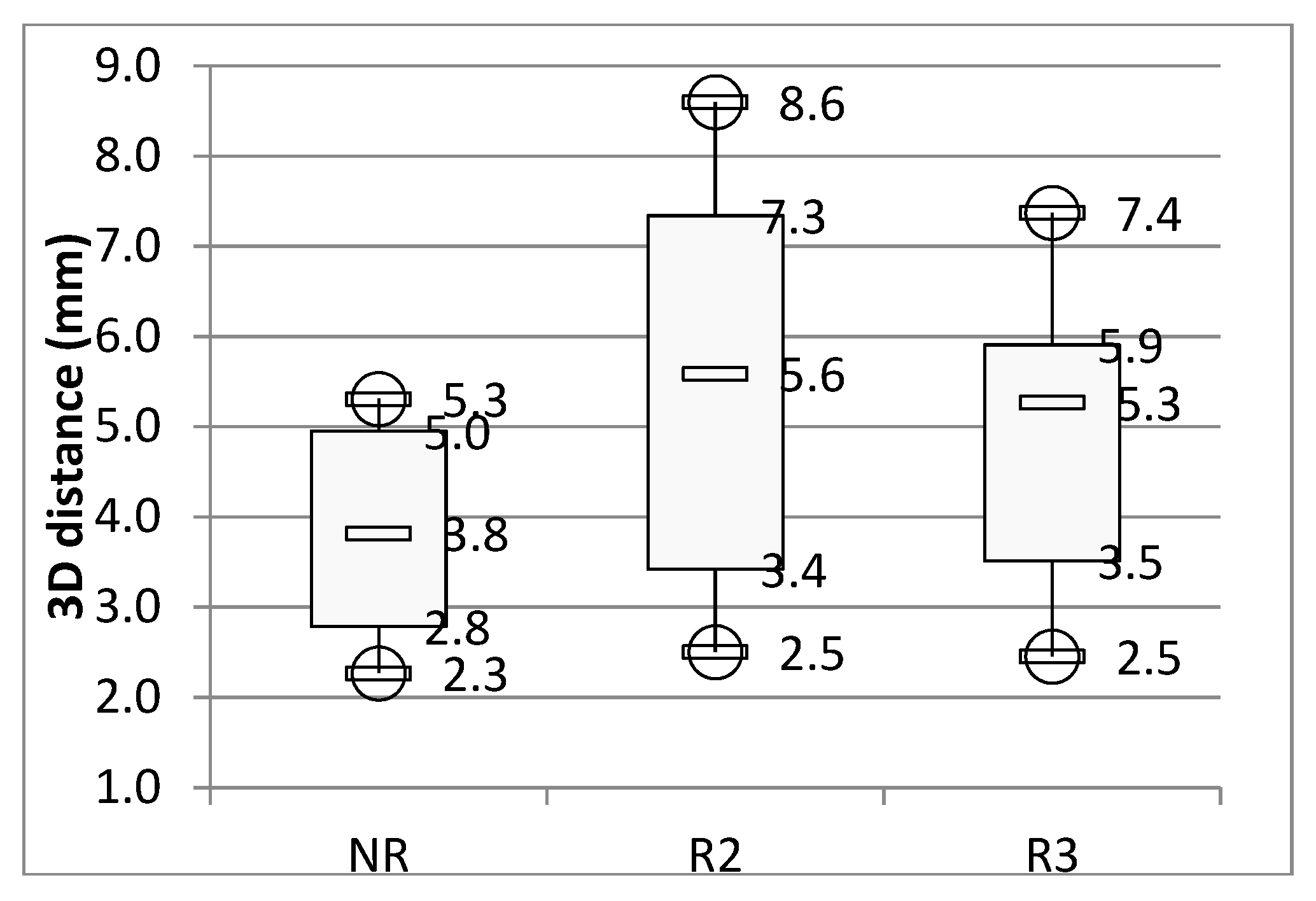
Figure 3 shows the global precision of each registration method, in the form of a box plot, representing the median, the first and third quartiles and the maximum and minimum values. Here and for the rest of the document, the term global precision refers to the mean registration errors for all ostia. The mean global precision of the NR method is 3.8 (SD 1.3) mm; R2D method is 5.6 (SD 2.7) mm; R3D method is 5.3 (SD 1.6) mm. Concerning only renal ostia—NR is 2.6 (SD 1.3) mm; R2D is 2.7 (SD 0.9) mm and R3D is 5.3 (SD 3.0) mm. The mean residual RMS on landmarks positioning is 0.8 mm for R3D. Figure 4 shows the precision of the three different registration methods. It represents the distance between the ostia of the registered geometries and the target ostia, for each ostium. Figure 5 shows the reconstructed aortas after the non-rigid registration, compared with the target volumes.

4. Discussion

The objective of this study was to introduce and to evaluate our novel non-rigid registration technique, which is based on a mechanical model. For this purpose, the performances of the method were compared to a 3D/3D rigid registration method and a 2D/3D rigid registration method, both state-of-the-art in current fusion imaging registration methods. After prior discussion with expert vascular surgeons, the acceptability value has been set below 5mm on ostia. The overall accuracy of the registration changes from low (x > 5mm) for the 2D rigid method to good (3 mm < x < 5 mm) for the non-rigid method according to the scale of Kauffmann et al. [5]. A first qualitative visual comparison between the target aortas and the reconstructed aortas (Figure 5) gave an overview of the results—the registration in the projection plane (front view) is highly accurate. The registration outside the projection plane is globally less precise but remains acceptable (<5 mm), except for the tortuous geometry of patient 5, where accuracy on the renal arteries is acceptable but should be improved for the mesenteric and celiac trunk arteries, outside the projection plane. When comparing the overall accuracy of the different methods in Figure 3, it appears that the non-rigid method is the most accurate, ahead of 3D rigid registration and 2D rigid registration. The improvement of accuracy between these methods shows the added value of the non-rigid aspect of registration, even for an aorta subjected to low natural deformations. Moreover, the non-rigid method is more robust. The registration errors are contained in a limited range, while the errors approach 10 mm for the 2D rigid registration in some cases. However, for renal arteries, non-rigid registration, although qualified as good according to Kauffmann et al. [5], remains qualitatively below 2D rigid registration. The non-rigid and 2D rigid methods are rigidly registered in the same way on the renal arteries. Consequently, the ostia position of renal arteries is slightly modified during the deformation of the non-rigid model, mainly along the antero-posterior axis, outside the registration plane. This is one of the limitations of the method, which seeks to achieve an overall mechanical balance. Weighting the important points could solve the problem in future developments. The one view 2D/3D non-rigid method achieves a better accuracy than the rigid registration methods presented in this study. However, this simple method, with a calculation time of less than half a second using Matlab®, could be perfectly adapted to the surgery workflow. Indeed, after discussions with vascular surgeons, the maximum allowed duration for a simulation during a surgical procedure was set to 1 min. Here, calculation time refers to computing the deformation field and to registration, including the finite element analysis. In addition, it requires only one DSA taken from a single incidence, theoretically reducing the patient’s irradiation rate. The registration accuracy for both renal arteries (2.5 mm) is qualified as high according to the scale of Kauffmann et al. [5] and is therefore satisfactory for surgical use. The accuracy of the registration obtained is slightly lower than the Zheng method. However, unlike Zheng et al. [25], we do not directly compare the positions of 2D points with 3D points. We compare the position of two sets of 2D points and we perfectly know the correspondence between the projected 2D initial points and 3D initial points. Therefore, we can minimize the registration error. Moreover, our non-rigid method is based on a FEM rather than Zheng et al. [25] and Groher et al. [24]. It integrates the actual mechanical characteristics of the aorta, such as diameter, thickness and Young’s modulus. Indeed, the diameter and thickness of the aorta are integrated into the stiffness matrix K via the cross-sectional area of the beam A and the cross section moments of inertia I as described in Appendix A in supplemental materials. Simulation results remain stable for Young’s modulus E ranging between 7 and 13 MPa [27,28]. It is therefore possible to implement new functions in the code, such as the navigation of guidewires, in a mechanically consistent model and without significant modifications to the existing code. In summary, it is possible to simulate in real time the deformation of the aorta induced by device insertion during the intervention using the same model.
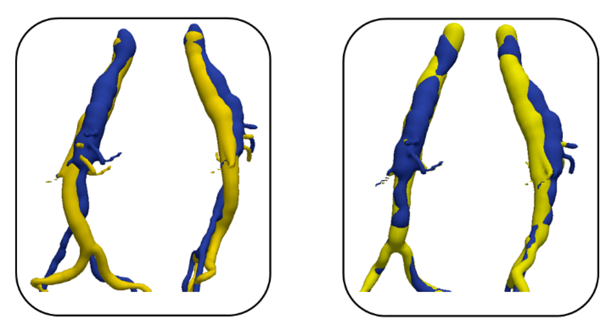
To evaluate the model with large deformations, the method was tested on an artery deformed by a stent-graft launcher. For the sake of verification, the target artery is deformed using a finite element simulation and does not correspond to actual clinical data but the imposed deformations, reviewed and validated by a vascular surgeon, are similar to a real case. As shown in Figure 6, the method is able to handle large deformations, with a mean accuracy of 6.3 (SD 2.3) mm and an accuracy for the right and left renal arteries of 3.3 and 2.2 mm respectively. Therefore, this recalibration method enables to set up a mechanical model of the aorta, updated according to operating data and suitable for clinical applications. However, more tests with large deformations should be conducted for confirmation.
The aorta model still suffers from several limitations that can reduce, in some cases, the accuracy of the method, especially regarding boundary conditions. For example, the anchorage points of the aorta and the surrounding structures are not considered, in particular the spine, which can significantly change the mechanical behavior of the aorta [19]. This should be implemented in a future version of the method. The local stiffness of the aorta is also not considered, although it can vary significantly, for example in the case of different thrombus size or calcification, which are not included in the segmentation of the lumen. As a result, the deformations of the artery would be different, which should be taken into account in a finite element analysis. Therefore, future versions of our methodology should consider these parameters and the underlying local modifications of the stiffness applied to the simplified model of the aorta. However, as our simulations are guided by intraoperative imaging, deformations due to the presence of thrombus and calcification are already partially taken into account, which should minimize errors. The method has other limitations. It depends on the projection matrix and assumes it to be known. Its accuracy depends on the reliability of the matrix. To ensure the stability and robustness of the method, it should be tested with more patients, including cases that are more tortuous. Finally, the evaluation of the methodology used fluoroscopy data taken in similar conditions. We are now considering verification with CT scans acquired at a different time and in different conditions, as our methodology was designed to handle such situations.
As current 3D/3D fusion imaging systems are not optimal for EVAR procedures, we proposed a new 2D/3D registration method making a good trade-off between performances, precision and simplicity. After a comprehensive presentation of the method, we showed its performances on clinical datasets for which a reference CT scan was available to evaluate the registration errors and to compare them with other registration methods based on rigid transformations. The study permitted to evaluate the natural deformations of the aorta observed between two consecutive scan and to differentiate the non-rigid deformations from the rigid displacements. It appeared that a non-rigid registration method is essential to register accurately ostia positions. We also proved that the method was able to handle large deformations induced by tool insertions. Therefore, our method can represent a significant improvement for fusion imaging in EVAR procedures as it has also the potential to reduce patient irradiation and, unlike current 3D/3D methods, it does not require hybrid room facilities. Combined with simulations performed at the planning stage of EVAR [29,30,31,32], this will participate in the uptake of computer simulations for assisting surgical interventions in future medicine.

5. Patents

A work-related patent has been submitted under the name “Simulation Améliorée du Déploiement d’une Endoprothèse en Temps Réel,” France N°1908569. Depositors: Thales/ASS Armines/Université Jean Monnet/Centre Hospitalier Universitaire.

Author Contributions

Conceptualization, A.P., B.P., S.G., J.-N.A. and S.A.; Data curation, A.P.; Formal analysis, A.P.; Funding acquisition, S.G. and S.A.; Investigation, A.P.; Methodology, A.P., B.P. and S.A.; Project administration, S.G. and S.A.; Resources, J.-N.A. and S.A.; Software, A.P. and B.P.; Supervision, S.G. and S.A.; Validation, A.P. and B.P.; Visualization, A.P.; Writing—original draft, A.P.; Writing—review & editing, A.P., B.P. and S.A. All authors have read and agreed to the published version of the manuscript.

Funding

This research received no external funding.

Conflicts of Interest

The authors declare no conflict of interest.

Appendix A

Appendix A.1. Non-Rigid Registration (NR)

This part is dedicated to the description of the non-rigid registration method (NR). The aim of this method is to find the displacement U to minimize the potential energy π(U) of the aorta. The appendix is an optional section that can contain details and data supplemental to the main text.
U = argmin   π ( U ) s . t .   ( u , v ) = P . ( X 0 + U )
(u,v) are the 2D coordinates of the key points extracted from intraoperative images. X0 are the initial 3D coordinates of the key points from preoperative CT scan. U stands for the 3D displacements solutions of Equation (A1). P is the projection matrix.
With:
π ( U ) = V w d V V f i   u i d V S T T i u i d S
w is the strain energy density function; V the volume of the elastic body; Ti the ith component of the surface traction; ui the ith component of the deformation; Fi the ith component of a body force; ST the portion of the body surface over which tractions are prescribed. This minimization problem is solved with a traditional finite element model. A detailed flowchart of the proposed framework for the finite element model of the non-rigid registration method is shown in Figure 2. The initial configuration of the model is based on data extracted from preoperative CT scans, the initial centerline composed of a list of 3D points X0 associated with a connectivity table. The model is constrained with data extracted from intraoperative images. The projection of the initial centerline is registered onto the fluoroscopy. Those 2D constraints are translated in 3D via Lagrange multipliers and the related equations M are implemented as complementary equation to the finite element model (FEM) resolution (Equation (A12)). The model properties include the stiffness matrix K, involving 2 constants (Young’s modulus E, Poisson’s ratio ν) and 2 dimensional parameters (the diameter of the aorta d and the wall thickness e). The aorta is finally reconstructed. We assume that the projection matrix and the patient orientation on the table are known. Thus, errors in the matrix directly affect the performance of the method. Geometric nonlinearities are neglected in the finite element model.

Appendix A.1.1. Initial Configuration

First, the geometry of the aorta is extracted from the DICOM stack of the preoperative CT scan with a front collision method implemented in VMTK [26]. This method consists in defining several seeding points on the image. Fronts propagate from the seeds with their speed proportional to the voxel intensity. The region where the two fronts collide is then the initial model. The segmented aorta is extracted as a 3D mesh composed of triangular elements. Then, the centerline of the initial geometry is extracted using the Voronoi diagram method implemented in the VMTK library. Centerlines are determined as weighted shortest paths traced between two extremal points. In order to ensure that the final lines do not lie anywhere in space, they are bound to run on the Voronoi diagram of the vessel model. For every point belonging to the Voronoi diagram, there is a sphere centered in that point that is a maximal inscribed sphere (the information relative to the radius is therefore defined everywhere on the Voronoi diagram). This initial centerline is then implemented in the FEM. The centerline is represented by a matrix of 3D points X0 associated with radius of inscribed sphere and a connectivity table. This centerline is then implemented as the initial geometry of the FEM.

Appendix A.1.2. Model Constrains

The target data consist of a single Digital Subtraction Angiography (DSA) taken from a single angle of incidence. This DSA is the projected shadow of the target aortic volume. The projection parameters are supposed to be known. A projection matrix is composed of the intrinsic parameter matrix C which contains the properties of the camera.
C = [ α u 0   u 0   0 α v v 0   0 0 1 ]
α α and α v . express the focal length, in number of pixels (respectively in horizontal and vertical directions); u 0 and v 0 are the coordinates of the principal point, expressed in the pixel reference frame. The position and the orientation of the camera are expressed by a 3D rotation matrix R and a 3D translation matrix t. The 3 × 4 projection matrix P is:
P = CR ( I t )

Appendix A.1.3. 2D/2D Non-Rigid Registration

It would have been possible to extract the target centerline directly from the projection of the target volume but the point-to-point association of two different CLs projection creates errors and increases the calculation time, due to the lack of information out of the projection plane. The conservation of the initial centerline points throughout the process allows maintaining a perfect match between the 3D centerline points and the 2D centerline points. Thus, the first step is a 2D/2D non-rigid registration of the projection of the initial centerline on the target images.
The geometry implemented in the FEM model, that is the centerline of preoperative aorta, is then projected according to the projection parameters. First, a 3D/2D rigid registration is performed between the projection of the initial centerline and the intraoperative shadow of the target aorta from the DSA, to initiate the non-rigid registration. This was done manually for this study but many studies presented 3D/2D rigid registration method, for example Groher et al. [24]. Then the centerline is projected again, to obtain a new set of projected points SCL(xcl,ycl), to perform the non-rigid registration. The rigidly registered centerline is then interpolated to be aligned onto the shape of the target, in 2D. We do not use the CL of the 2D target, which is not extracted. A set of landmarks is positioned on the projection of the preoperative aorta, named S12D(x12D,y12D). Another set of landmarks is positioned on the target image at the same physiological points, named S22D(x22D,y22D). S12D and S22D are used to obtain two displacement vectors:
{ v x = x 2 2 D x 1 2 D v y = y 2 2 D y 1 2 D
The data are interpolated with the griddata Matlab® function, using biharmonic spline interpolation, based on Green functions. It may be written:
v q = g r i d d a t a ( x , y , v , x q , y q )
where (x,y) are the former coordinates related to the sample values v; vq are the updated values interpolated on the new coordinates (xq,yq). So here:
{ v x i = g r i d d a t a ( x 1 2 D , y 1 2 D , v x , x c l 1 , y c l 1 ) v x i = g r i d d a t a ( x 1 2 D , y 1 2 D , v y , x c l 1 , y c l 1 )
v x i and v y i are the interpolated displacement vectors of the new centerline 2D points. Green functions of the biharmonic operator, in one and two dimensions, are used for minimum curvature interpolation of irregularly spaced data points. The interpolating curve is a linear combination of Green functions centered at each data point [33]. The result is a 2D/2D non-rigid registration of the projection of the initial centerline onto the target, which must be translated in 3D deformations.

Appendix A.1.4. Back Projection Lines

Then, the 2D registration must be transferred to the 3D model. The points of the 2D initial centerline are back-projected to obtain back-projection lines that will serve as “rails” on which the points of the 3D initial centerline are “guided.” Each point of the finite element model is free to move along his corresponding back-projection lines. The deformations necessary to reach an equilibrium state are computed by the mechanical model. Displacements are assigned to the 3D model via Lagrange multipliers in addition to the stiffness matrix as shown previously. The equations of the projection lines result from basic Cartesian geometry. The X-ray source is the origin of the global coordinate system. Therefore, all projection lines have a common point O (0,0,0). The projection parameters are known, along with the position of the target image in 3D space, representing the layout of the X-ray source and the flat panel detector. Thus, each target point P(x,y,z) of the image is associated with a back-projection line running through this point and through the origin. The normalized vector of the line is therefore:
v = ( P O ) ( P O )
The points of the model are forced to follow these lines, prescribe as constraints using Lagrange multipliers.

Appendix A.2. Finite Element Model Resolution

Appendix A.2.1. Model Properties

The centerline is imported as a matrix of 3D points associated with radii of inscribed spheres and a connectivity table. Each point becomes a node of the model and beam elements are created between every consecutive node pair. The elements are linked together with the connectivity table. Each node has 6 degrees of freedom U, 3 translations and 3 rotations. The central line of the aorta is modeled as a series of beam elements within a finite element code. This centerline was previously extracted by image segmentation from the pre-operative CT scan. Each beam has a 12 × 12 elementary stiffness matrix Ke calculated in local coordinates that relates angular and spatial position of each end of a beam element to the forces and torques applied to them [34]:
K e = E l [ A 0 12 I z l 2 ( 1 + Φ y ) 0 0 12 I y l 2 ( 1 + Φ z ) 0 0 0 G J E S y m m e t r i c 0 0 6 I y l ( 1 + Φ z ) 0 ( 4 + Φ z ) I y 1 + Φ z 0 6 I z l ( 1 + Φ y ) 0 0 0 ( 4 + Φ y ) I z 1 + Φ y A 0 0 0 0 0 A 0 12 I z l 2 ( 1 + Φ y ) 0 0 0 6 I z l ( 1 + Φ y ) 0 12 I z l 2 ( 1 + Φ y ) 0 0 12 I y l 2 ( 1 + Φ z ) 0 6 I y l ( 1 + Φ z ) 0 0 0 12 I y l 2 ( 1 + Φ z ) 0 0 0 G J l 0 0 0 0 0 G J E 0 0 6 I y l ( 1 + Φ z ) 0 ( 2 Φ z ) I y 1 + Φ z 0 0 0 6 I y l ( 1 + Φ z ) 0 ( 4 + Φ z ) I y 1 + Φ z 0 6 I z l ( 1 + Φ y ) 0 0 0 ( 2 Φ y ) I z 1 + Φ y 0 6 I z l ( 1 + Φ y ) 0 0 0 ( 4 + Φ y ) I z 1 + Φ y ]
With G = E 2 ( 1 + v ) where E is the Young’s modulus and ν the Poisson’s ratio; I y and I z are cross-section moments of inertia; A is the cross-sectional area of the beam, l its length; φ y and φ z represent shear deformation parameters and are defined as φ y = 12 E I z G A s y l 2 and φ z = 12 E I z G A s y l 2 with Asy and Asz the shear area in the y and z directions. Elementary stiffness matrices Ke of each beam elements are then assembled together into a global stiffness matrix K. Since Ke is initially calculated in local coordinates, a transformation matrix is applied to express Ke in the global coordinate system. As each element DoFs are in global coordinates and as the topology is a simple sequence of segments, the resulting global stiffness matrix K is block-tri-diagonal. This type of system can be solved very efficiently [31]. This centerline is the simplified representation of the aorta and will be deformed during the next steps according to target data. The boundary conditions are limited to zeroing the translations of a single reference point positioned between the renal ostia.

Appendix A.2.2. FEM Resolution with Lagrange Multipliers

This part described the simplified resolution of the finite element model. First, displacements U are imposed to position the nodes on their corresponding back-projection line. The reaction forces F are derived from:
K U = F
Then the positions of the nodes are updated and a new stiffness matrix K’ is computed. Lagrange multipliers allow new multi-freedom constraints (MFCs) to be prescribed onto the FEM by adding equations to the stiffness matrix. In our case, Lagrange multipliers are used to constrain nodal displacements to remain along the projection lines. The direction vector (Equation (A8)) is implemented as Lagrangian multipliers, which constrain the translation degrees of freedom according to:
u v w χ ψ ω [ a b c 0 0 0 ]
These additions are made in the matrix M. M is a mxn matrix, with m = (number of constrain nodes) and n = 6 × (number of nodes):
M = u 1 [ a 1 0 0 v 1 b 1 0 0 w 1 c 1 0 0 χ 1 0 0 0 ψ 1 0 0 0 ω 1 0 0 0 u 2 0 a 2 0 v 2 0 b 2 0 w 2 0 c 2 0 χ 2 0 0 0 ψ 2 0 0 0 ω 2 0 0 0 u n 0 0 a n v n 0 0 b n w n 0 0 c n χ n 0 0 0 ψ n 0 0 0 ω n 0 0 0 ]
M is added to the stiffness matrix K’:
[ K M T M 0 ] [ U λ ] = [ F F λ ]
Finally, the equation is solved to find U.’ The calculated displacements U’ are therefore forced to respect the equations of the lines implemented in M. The displacements are added to the previous position of the nodes to find their new position.

Appendix A.2.3. 3D Reconstruction

Finally, the 3D volume is reconstructed with a VMTK function. 3D spheres associated with each point of the central line are merged to create the mesh corresponding to the new surface, which is consequently defined by a set of 3D points and triangular elements. Surface details of the aorta are lost but the general volumes and most importantly the position of the ostia, are well represented.

Appendix B

Appendix B.1. Evaluation

The previous part presents the non-rigid registration method based on a FEM of the centerline of the aorta. Three registration methods are now compared in this section to evaluate the performance of the non-rigid registration method.
The first method is the main 2D/3D non-rigid registration method (NR) itself. This method is then compared to rigid registration methods currently used for fusion imaging. The surgeons we are collaborating with currently use these methods; therefore, we use them as a standard to evaluate the performance of our approach. The first rigid registration method is the 3D/3D registration already described below as the spine registration method (R3D). This method aligns two 3D volumes and consequently requires 3D imaging at the beginning of the procedure, which is only possible in hybrid rooms. The second one is the 2D rigid registration method (R2D) performed on the aorta shape, derived from the non-rigid registration process. This registration is representative of a 2D/3D rigid registration method and does not require hybrid rooms. These methods are not able to process non-rigid deformations. By comparing their results with the non-rigid method proposed here, we will determine whether the non-rigid aspect is relevant or not and evaluate the contribution of the mechanical model. Natural deformations undergone by the aorta between consecutive CT scans acquired several months apart constitute a significant case study for the image registration problems considered in this paper. To evaluate the performance of the centerline (CL) deformation method, we used two CT scans for each patient to simulate the clinical data. The first CT scan represents the preoperative CT scan used to extract the 3D geometry implemented in the model. The second CT scan was used to simulate intra-operative 2D AAA target fluoroscopies. Thus, the target 3D geometry is known, which allows us to precisely measure the performance of our registration method but also to compare it with a 3D/3D registration method. This image simulation can be used to make assumptions for possible clinical application: the projection matrix is known and the artery has a perfect circular cross-section.

Appendix B.2. 3D Rigid Registration (R3D)
The NR method was presented previously. We now briefly present the spine rigid registration method (R3D). To perform this method, a simple rigid transformation T is used, parameterized by 6 degrees of freedom with Mij describing the 3D rotation matrix and ti the 3D translations.
T = [ M 11 M 12 M 13 t x M 21 M 22 M 23 t y M 31 M 32 M 33 t z 0 0 0 1 ]
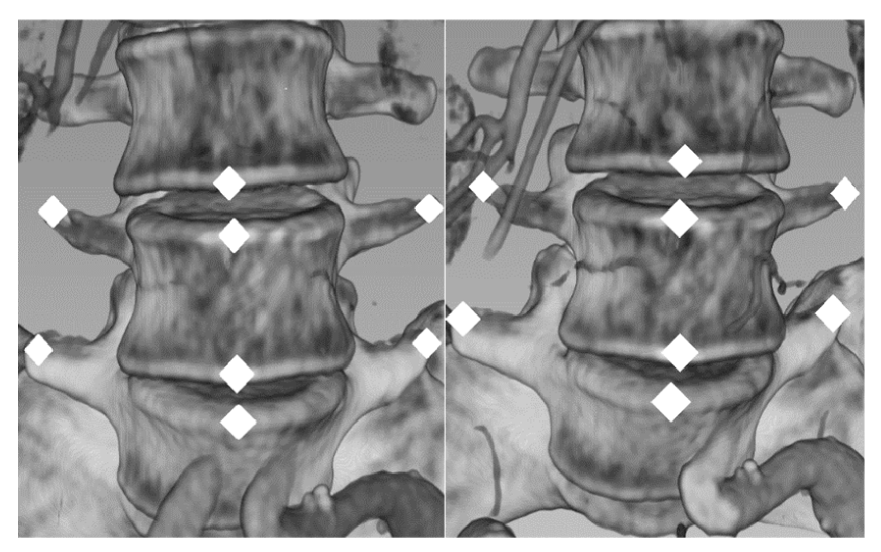
The aorta and spine volumes are reconstructed from Dicom images with 3Dslicer®: volume V1 for CT scan 1 and V2 for CT scan 2. Then, fiducial markers are manually positioned on anatomical landmarks on V1 and V2 (Figure A1); a set of 3D Ss points are positioned for each scan on lumbar spinal landmarks. Ss1 was placed on V1; Ss2 on V2. S is on the following form, with n the number of landmarks:
S = [ x 1 x n y 1 y n z 1 z n 1 1 ]
Ts, related to Ss, is computed to minimize the RMS errors between the two point clouds Ss1 and Ss2, such as:
R M S E r r o r s = i = 1 n ( T   S i 1 S i 2   ) 2 n
And:
a r g m i n ( R M S E r r o r s ) = T s
Figure A1. Landmarks on CT scan 1: Ss1 and CT scan 2: Ss2.
Modelling 01 00002 g0a1
Ts is the rigid transformation to register the spine position. This method is the gold standard, since it is commonly performed at the beginning of fusion imaging in hybrid operating rooms on lumbar vertebra or iliac bones.

Appendix B.3. 2D Rigid Registration (R2D)

Rigid 2D/2D registrations are part of the currently used methods during surgery. We included it in our research to compare the results of our method with this other 2D based registration method and to evaluate the relevance of a non-rigid registration. This method simply consists in a rigid registration of the projected initial aorta on the target aorta from the DSA. It derives from the first step of the 2D/2D non rigid registration.

Appendix B.4. Measurement

The distance between key points of the aorta is measured to compare the accuracy of the registration methods. This distance characterizes the registration error of the method for the points of interest related to the surgery, that is, the ostia of the abdominal aorta: right and left renal, right and left iliac, superior mesenteric and coeliac arteries. For each CT scan, the 3D position of each ostium is taken 5 times. The mean point is calculated for each ostium and the distance between corresponding ostia of the reference and registered volume is measured. The measurement uncertainty simply results in the difference between the 5 measurements taken for each ostia.

References

  1. Anahita, D.; SreyRam, K.; Cheong, J.L.; Gilbert, R.U.; Sapan, S.D. Epidemiology of aortic aneurysm repair in the United States from 2000 to 2010. J. Vasc. Surg. 2014, 59, 1512–1517. [Google Scholar]
  2. Sajid, M.S.; Desai, M.; Haider, Z.; Baker, D.M.; Hamilton, G. Endovascular aortic aneurysm repair (EVAR) has significantly lower perioperative mortality in comparison to open repair: A systematic review. Asian J. Surg. 2008, 31, 119–123. [Google Scholar] [CrossRef]
  3. Halliday, A.W.; The United Kingdom EVAR Trial Investigators. Endovascular Repair of Aortic Aneurysm in Patients Physically Ineligible for Open Repair. N. Engl. J. Med. 2010, 362, 1863–1871. [Google Scholar]
  4. Macdonald, S.; Lee, R.; Williams, R.; Stansby, G. Towards safer carotid artery stenting: A scoring system for anatomic suitability. Stroke 2009, 40, 1698–1703. [Google Scholar] [CrossRef]
  5. Kauffmann, C.; Douane, F.; Therasse, E.; Lessard, S.; Elkouri, S.; Gilbert, P.; Beaudoin, N.; Pfister, M.; Blair, J.-F.; Soulez, G. Source of Errors and Accuracy of a Two-Dimensional/Three-Dimensional Fusion Road Map for Endovascular Aneurysm Repair of Abdominal Aortic Aneurysms. J. Vasc. Interv. Radiol. 2015. [Google Scholar] [CrossRef]
  6. Markelj, P.; Tomaževič, D.; Likar, B.; Pernuš, F. A review of 3D/2D registration methods for image-guided interventions. Med Image Anal. 2012, 16, 642–661. [Google Scholar] [CrossRef]
  7. Yu, W.; Tannast, M.; Zheng, G. Non-rigid free-form 2D–3D registration using a B-spline-based statistical deformation model. Pattern Recognit. 2017, 63, 689–699. [Google Scholar] [CrossRef] [Green Version]
  8. Miao, S.; Wang, Z.J.; Liao, R. A CNN Regression Approach for Real-Time 2D/3D Registration. IEEE Trans. Med. Imaging 2016, 35, 1352–1363. [Google Scholar] [CrossRef]
  9. Chen, F.; Liu, J.; Liao, H. 3D Catheter Shape Determination for Endovascular Navigation Using a Two-Ste. IEEE Trans. Med. Imaging 2017, 36, 685–695. [Google Scholar] [CrossRef]
  10. Gorges, S.; Kerrien, E.; Berger, M.-O.; Trousset, Y.; Pescatore, J.; Anxionnat, R.; Picard, L. Model of a Vascular C-Arm for 3D Augmented Fluoroscopy in Interventional Radiology. Med. Image Comput. Comput. -Assist. Interv. Miccai 2005, 8, 214–222. [Google Scholar]
  11. Tacher, V.; Lin, M.; Desgranges, P.; Deux, J.-F.; Grünhagen, T.; Becquemin, J.; Luciani, A.; Rahmouni, A.; Kobeiter, H. Image Guidance for Endovascular Repair of Complex Aortic Aneurysms: Comparison of Two-dimensional and Three-dimensional Angiography and Image Fusion. J. Vasc. Interv. Radiol. 2013, 24, 1698–1706. [Google Scholar] [CrossRef] [Green Version]
  12. Hertault, A.; Maurel, B.; Sobocinski, J.; Gonzalez, T.M.; le Roux, M.; Azzaoui, R.; Midulla, M.; Haulon, S. Impact of Hybrid Rooms with Image Fusion on Radiation Exposure during Endovascular Aortic Repair. Eur. J. Vasc. Endovasc. Surg. 2014, 48, 382–390. [Google Scholar] [CrossRef] [PubMed] [Green Version]
  13. de Ruiter, Q.M.B.; Reitsma, J.B.; Mol, F.L.; van Herwaarden, J.A. Meta-analysis of Cumulative Radiation Duration and Dose During EVAR Using Mobile, Fixed, or Fixed/3D Fusion C-Arms. J. Endovasc. Ther. 2016, 23, 944–956. [Google Scholar] [CrossRef] [PubMed]
  14. Varnavas, A.; Carrell, T.; Penney, G. Fully automated 2D–3D registration and verification. Med. Image Anal. 2015, 26, 108–119. [Google Scholar] [CrossRef]
  15. Maurel, B.; Hertault, A.; Gonzalez, T.M.; Sobocinski, J.; le Roux, M.; Delaplace, J.; Azzaoui, R.; Midulla, M.; Haulon, S. Evaluation of Visceral Artery Displacement by Endograft Delivery System Insertion. J. Endovasc. Ther. 2014, 21, 339–347. [Google Scholar] [CrossRef] [PubMed]
  16. Kaladji, A.; Dumenil, A.; Castro, M.; Cardon, A.; Becquemin, J.; Bou-Saïd, B.; Lucas, A.; Haigron, P. Prediction of deformations during endovascular aortic aneurysm repair using finite element simulation. Comput. Med. Imaging Graph. 2013, 37, 142–149. [Google Scholar] [CrossRef] [Green Version]
  17. Kaladji, A.; Villena, A.; Pascot, R.; Lalys, F.; Daoudal, A.; Clochard, E.; Lucas, A.; Cardon, A. Fusion imaging for EVAR with mobile c-arm. Ann. Vasc. Surg. 2018, 55. [Google Scholar] [CrossRef]
  18. Gindre, J.; Bel-Brunon, A.; Kaladji, A.; Duménil, A.; Rochette, M.; Lucas, A.; Haigron, P.; Combescure, A. Finite element simulation of the insertion of guidewires during an EVAR procedure: Example of a complex patient case, a first step toward patient-specific parameterized models. Int. J. Numer. Methods Biomed. Eng. 2015, 31. [Google Scholar] [CrossRef] [PubMed]
  19. Gindre, J.; Bel-Brunon, A.; Rochette, M.; Lucas, A.; Kaladji, A.; Haigron, P.; Combescure, A. Patient-Specific Finite-Element Simulation of the Insertion of Guidewire During an EVAR Procedure: Guidewire Position Prediction Validation on 28 Cases. IEEE Trans. Biomed. Eng. 2017, 64, 1057–1066. [Google Scholar] [CrossRef]
  20. Mohammadi, H.; Lessard, S.; Therasse, E.; Mongrain, R.; Soulez, G. A Numerical Preoperative Planning Model to Predict Arterial Deformations in Endovascular Aortic Aneurysm Repair. Ann. Biomed. Eng. 2018, 46, 2148–2161. [Google Scholar] [CrossRef]
  21. Liao, R.; Tan, Y.; Sundar, H.; Pfister, M.; Kamen, A. An Efficient Graph-Based Deformable 2D/3D Registration Algorithm with Applications for Abdominal Aortic Aneurysm Interventions. In Proceedings of the MIAR 2010: Medical Imaging and Augmented Reality, Beijing, China, 19–20 September 2010. [Google Scholar]
  22. Toth, D.; Pfister, M.; Maier, A.; Kowarschik, M.; Hornegger, J. Adaption of 3D models to 2D x-ray images during endovascular abdominal aneurysm repair. In Proceedings of the Medical Image Computing and Computer-Assisted Intervention—MICCAI 2015, Munich, Germany, 5–9 October 2015. [Google Scholar]
  23. Raheem, A.; Carrell, T.; Modarai, B.; Penney, G. Non-rigid 2D-3D image registration for use in Endovascular repair of Abdominal Aortic Aneurysms. Med. Image Underst. Anal. 2010, 15. [Google Scholar]
  24. Groher, M.; Zikic, D.; Navab, N. Deformable 2D-3D Registration of Vascular Structures in a One View Scenario. IEEE Trans. Med. Imaging 2009, 28. [Google Scholar] [CrossRef]
  25. Zheng, J.Q.; Zhou, X.Y.; Riga, C.; Yang, G.Z. Towards 3d path planning from a single 2d fluoroscopic image for robot assisted fenestrated endovascular aortic repair. Int. Conf. Robot. Autom. (Icra) 2019, 8747–8753. [Google Scholar] [CrossRef]
  26. The Vascular Modeling Toolkit. Available online: www.vmtk.org (accessed on 24 October 2018).
  27. Bergel, D.H. The static elastic properties of the arterial wall. J. Physiol. 1961, 445–457. [Google Scholar] [CrossRef]
  28. Veer, M.V.; Buth, J.; Merkx, M.; Tonino, P.; van den Bosch, H.; Pijls, N.; van de Vosse, F. Biomechanical properties of abdominal aortic aneurysms assessed by simultaneously measured pressure and changes in human. J. Vasc. Surg. 2008, 1401–1407. [Google Scholar] [CrossRef] [Green Version]
  29. Derycke, L.; Sénémaud, J.; Perrin, D.; Avril, S.; Desgranges, P.; Albertini, J.N.; Haulon, S. Patient Specific Computer Modelling for Automated Sizing of Fenestrated Stent Grafts. Eur. J. Vasc. Endovasc. Surg. 2020, 59, 237–246. [Google Scholar] [CrossRef]
  30. Derycke, L.; Perrin, D.; Cochennec, F.; Albertini, J.N.; Avril, S. Predictive numerical simulations of double branch stent-graft deployment in an aortic arch aneurysm. Ann. Biomed. Eng. 2019, 47, 1051–1062. [Google Scholar] [CrossRef] [Green Version]
  31. Santamaría, V.A.A.; Daniel, G.; Perrin, D.; Albertini, J.N.; Rosset, E.; Avril, S. Model reduction methodology for computational simulations of endovascular repair. Comput. Methods Biomech. Biomed. Eng. 2018, 21, 139–148. [Google Scholar] [CrossRef] [PubMed] [Green Version]
  32. Perrin, D.; Badel, P.; Orgéas, L.; Geindreau, C.; Dumenil, A.; Albertini, J.N.; Avril, S. Patient-specific numerical simulation of stent-graft deployment: Validation on three clinical cases. J. Biomech. 2015, 48, 1868–1875. [Google Scholar] [CrossRef] [PubMed] [Green Version]
  33. Sandwell, D.T. Biharmonic spline interpolation of GEOS-3 and SEASAT altimeter data. Geophys. Res. Lett. 1987. [Google Scholar] [CrossRef] [Green Version]
  34. Duriez, C. Real-time haptic simulation of medical procedures involving deformations and device-tissue interactions. Ph.D. Thesis, Université des Sciences et Technologie de Lille–Lille I, Villeneuve-d’Ascq, France, 2013. [Google Scholar]
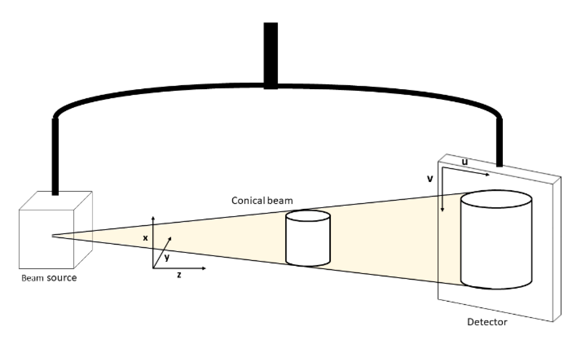
Figure 1. C-Arm configuration: patient reference frame and projected image reference frame.
Modelling 01 00002 g001
Figure 2. Detailed description of the different steps of our methodology.
Modelling 01 00002 g002
Figure 3. Box plots comparing global registration precisions of non-rigid (NR) and R2D 2D/2D registration methods and R3D 3D/3D registration methods as gold standard.
Modelling 01 00002 g003
Figure 4. Comparison of the performance of NR and R2D 2D/3D registration methods and R3D 3D/3D registration method as gold standard, with the mean and std precision error for each ostium.
Modelling 01 00002 g004
Figure 5. Visual comparison of non-rigid registration. Targets in blue, NR aorta in yellow, front and side views for each patient.
Modelling 01 00002 g005
Figure 6. Visual comparison of non-rigid registration. Targets in blue, NR aorta in yellow, front and side views for each patient; a. before registration; b. after registration.
Modelling 01 00002 g006
Table 1. Patients’ sex, age and CT scans intervals.
PatientSexAge at CT Scan 1CT Scans Intervals (Months)
1Female598
2Male786
3Male669
4Male684
5Male773
6Male545
7Male591