Abstract
The Volume Bragg Grating (VBG) imaging technique provides a novel approach to gaze-type hyperspectral imaging. However, collimation constraints of the incident beam during narrow-band filtering and high-spatial-resolution imaging introduce system complexity, hindering miniaturization and modularization of the optical system. To address these limitations, this paper proposes a convex transmissive VBG structure with tunable design parameters to enhance the field of view (FOV), relax collimation requirements, improve imaging quality, narrow filter spectral bandwidth, and simplify the optical system design. For the precise analysis and optimization of convex VBG performance, we established a physical model for filtered imaging using a convex transmissive VBG with polychromatic extended sources. An evaluation metric termed the “Maximal Splitting Angle (MSA)” was introduced to quantify the dispersion extent of image spots. This approach was employed to investigate the intrinsic correlations between structural parameters (such as the radius of curvature, vector tilt angle, grating period, and thickness) and key system performance indicators (spatial resolution and spectral resolution). The necessity of optimizing these parameters was rigorously demonstrated. Theoretical analysis confirms that convex transmissive VBG achieves superior spatial and spectral resolution over planar VBG under reduced collimation constraints. The experimental results show a 58.5% enhancement in spatial resolution and a 63.6% improvement in spectral bandwidth for the convex transmissive VBG system. Crucially, while planar transmissive VBG suffers from stray fringe interference during wavelength tuning, its convex counterpart remains unaffected. This study proposes a novel device structure, offering new perspectives for optimizing VBG-filtered spectral imaging systems.
1. Introduction
Spectral imaging technology is an organic integration of optical imaging and spectroscopic analysis techniques. Unlike the finite-thickness negative-index slabs [1], it enables the simultaneous acquisition of two-dimensional spatial information and spectral-dimensional information of targets. It has a wide range of applications in remote sensing and telemetry [2,3,4,5,6], environmental surveying [7], agriculture [8,9], and medicine [10,11]. Among the various technical approaches to spectral imaging, surface array imaging can capture monochrome images across the entire image planar and construct two-dimensional spatial and spectral information about the target through wavelength scanning. This approach effectively increases the amount of information obtained through optical detection and avoids issues associated with image splicing and fusion, offering superior imaging capabilities.
As the core spectral separation component in focal planar array spectral imaging systems, the optical filter functions to separate incident polychromatic light by wavelength, thereby acquiring target image information across different spectral bands, directly impacting the performance of focal planar array spectral imaging. Among the various filters applicable to focal planar array imaging, aside from traditional filter wheels, mainstream technological approaches include diffraction gratings, acousto-optic tunable filters (AOTFs), liquid crystal tunable filters (LCTFs), and volume Bragg grating (VBG).
Diffraction gratings typically employ a push-broom imaging mechanism, where the sensor is moved along the spatial dimension to collect target spectral information line by line, followed by post-processing to reconstruct the complete spatial–spectral data cube through image stitching methods. Both AOTF and LCTF utilize electrically tunable filtering mechanisms, enabling wavelength selection without the need for mechanical movement. Thus, compared to filter wheel methods that rely on motor-driven rotation to switch filters, they significantly increase the number of available spectral channels and enhance system flexibility. However, they face challenges such as difficulty in narrowing the filter spectral bandwidth and a substantial decrease in transmittance as the filter spectral bandwidth narrows [12,13,14,15].
VBG-based surface-array spectral imaging leverages the superior wavelength-selective properties of Bragg gratings to achieve narrowband filtering for area-array detectors [16]. This approach attains filter bandwidths at nanometer or sub-nanometer scales, enabling high-spectral-resolution (/100) and even hyperspectral (/1000) imaging [17,18]. The technique delivers critical advantages, including high spectral resolution, exceptional spectral transmittance, and rapid data acquisition capability.
A prevalent approach for achieving high spatial and spectral resolution employs a grating-pair complementary method [19,20]. This technique partially mitigates image planar blurring and significantly enhances spatial resolution [21]. However, it introduces additional diffraction stages that cause substantial energy loss and reduced transmittance [22]. Critically, prior studies lack theoretical analysis correlating VBG structural parameters with dispersion characteristics. To address this gap, the MSA metric [23] was adopted to establish parametric relationships between VBG configurations and image-point dispersion magnitude. This framework quantifies the impacts of chromatic blurring, diffractive aberration, and central wavelength deviation on spatial resolution. Nevertheless, optimization demands ultra-narrow dispersion angles (milliradian-range), while practical applications such as remote sensing typically involve wide-angle incident illumination—fundamentally constraining the scheme’s implementability.
However, attaining high spatial and spectral resolution in VBG systems imposes stringent specifications on front-end optical components. The conventional approach—enhancing collimation—constrains the FOV. Spatial–spectral dimensional scanning [24] offers an alternative that acquires 2D spatial–spectral data while relaxing front-end collimation requirements. Nevertheless, this method introduces three critical limitations: increased post-processing complexity, diminished spectral calibration accuracy, and inevitable transmittance degradation.
To advance system performance, this paper proposes a convex transmissive VBG structure with tunable parameters that reduces the incident beam divergence angle from 179.6 mrad to 4.5 mrad (97.5% decrease), simultaneously enhancing filtering imaging performance and reducing spectral imaging system complexity. Through constructing a physical model of planar VBG spectral imaging, we elucidate how grating structural parameters govern filtered imaging characteristics, with parameter optimization guided by the maximum separation angle evaluation function. The theoretical and experimental results demonstrate the convex VBG’s dual capacity to enhance spatial resolution (58.5%↑) and spectral resolution (63.6%↑) while suppressing spurious interference fringes, all achieved with 40% reduced front-end collimation requirements—yielding significant advancements for performance-structure co-optimization in VBG spectral imaging systems.
2. Theoretical Analysis and Discussion
Broad-spectrum diffuse illumination represents a form of incoherent illumination. The diffractive imaging system formed by a complex-color extended light source passing through a convex transmissive VBG constitutes a linear space-invariant system. This extended light source can be decomposed into a series of point sources with varying spectral components and non-uniform intensities, where the resultant diffraction pattern emerges from the incoherent superposition of their individual images. This paper analyzes a high-pressure xenon lamp with a wavelength range covering the visible spectrum. By establishing a right-handed coordinate system under the assumption of grating fringes being uniformly distributed along the y-direction, the diffraction characteristics of the VBG can be investigated through analyzing the light-field diffraction process within the meridional planar (-planar). The fundamental physical model simplifies to the diffraction of a monochromatic point source (wavelength ) located at spatial coordinates (, ) by the convex transmissive VBG, as illustrated in Figure 1. (Note that the incident light is white light).
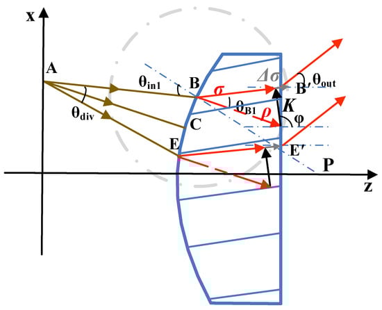
Figure 1.
Schematic of convex transmissive VBG structure and k-vector relationship. is the divergence angle, is the Bragg angle, is the vector tilt angle. Point A represents the point source; Point B is the incident point of the upper boundary ray of the light beam on the convex surface; Point B’ is the exit point of the upper boundary ray of the light beam on the planar surface; The center of the circular arc of the convex surface is located at point P.
First, the beam propagation process from polychromatic point sources at arbitrary spatial locations incident upon a VBG is investigated. Consider a point source A positioned at the focal point of a convex lens with focal length f and radius R, where an illumination spot of diameter D forms on the lens surface centered at point C. The distance L from A to C equals the lens focal length f and satisfies f = R/(− 1). The divergence angle of the beam incident on the convex transmissive VBG adheres to tan(/2) = (D/2)/L, yielding
When the beam propagates to the front surface of the convex transmissive VBG, it is assumed that the incident direction of the central ray aligns with the local radius of curvature of the VBG surface, while the central wavelength satisfies the Bragg condition given by Equation (2):
is the Bragg angle, is the vector tilt angle of VBG, is the average refractive index of VBG, and is the period of VBG.
For the upper marginal ray incident at point B on the convex surface (taking ray AB as representative case), denotes the angle between the incident ray at B and the z-axis, while represents the angular deviation from the central ray. During beam scanning, varies dynamically and can be approximated as . The incidence angle at point B satisfies the geometric relationship given by Equation (3), where L (the distance from point source A to central ray incidence point C) adheres to .
Upon refraction through the convex surface, the refracted ray forms a Bragg angle with the z-axis, exhibiting a wavevector within the volume grating. According to Kogelnik’s coupled-wave theory [15], the diffraction process modulated by grating vector redirects the incident wavevector , yielding a diffracted wavevector that satisfies
Herein, designates the phase mismatch, while and exhibit identical magnitudes of . The grating vector possesses a modulus . Although Equation (2) determines the central wavelength at the Bragg angle, the inherent spectral selectivity bandwidth of the volume grating—quantified as , where d denotes grating thickness—must be incorporated. Consequently, the maximum incident wavelength at point B is derived as , and the resultant longest output wavelength post-VBG diffraction becomes , ultimately yielding Equation (5):
Substituting Equation (5) into the vector relation Equation (4) yields diffraction angles for polychromatic components. Applying Snell’s law then determines the output angle . Similarly, for the marginal ray incident at point E, the minimum incident wavelength derivation must incorporate the volume grating’s inherent spectral selectivity bandwidth—analogous to Equation (5). For convex transmissive VBG, the maximum angular separation maintains identical formulation to planar VBG, expressed as
where and denote the output angles after VBG diffraction for the shortest diffractable wavelength and longest diffractable wavelength at the beam margin, respectively (the exit angles of B′ and E′ in Figure 1). The derivation process above innovatively analyzes the diffraction relationships of light waves in the meridional planar of a convex VBG based on coupled-wave theory.
The degree of dispersion of image points is directly correlated with the MSA, meaning the MSA can be used to characterize the blurring extent of the image spot. As indicated by the expression for MSA, the convex surface radius of curvature, period, average refractive index of the grating medium, and thickness of the grating significantly influence the MSA. To analyze the impact of structural parameters of the convex volume grating on the MSA, a specific set of VBG parameters was selected, as detailed in Table 1 (where refractive index modulation Δn = 0.00028, and this is not reflected in the expression of MSA):

Table 1.
Parameters of convex transmissive VBG.
This study first investigates the influence of the radius of the convex VBG. Under incident conditions of a diffusely reflected light field with a large beam divergence angle, the divergence angle becomes the primary factor affecting the filtering spectral bandwidth due to central wavelength drift. Selecting an appropriate curvature radius can minimize the divergence angle after the beam is refracted into the VBG. As illustrated in Figure 2a, the MSA value decreases with the increase in the radius of curvature, and the results are in agreement with the anticipated model behavior. However, the rate of change slows down as the radius of curvature grows larger. Meanwhile, further analysis of the relationship between the FOV angle of the convex transmissive VBG and the radius of curvature, as shown in Figure 2b, reveals that the FOV angle decreases as the radius of curvature increases. When R is greater than 90 mm, the FOV angle is half that when R is 40 mm, which exacerbates the quasi-regime limitation of the spectral imaging system. Therefore, the curvature radius of curvature should be selected based on the MSA and FOV requirements.
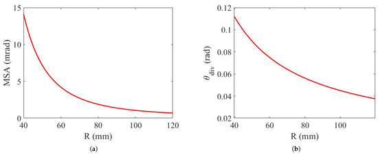
Figure 2.
Impact of curvature radius on MSA and FOV. (a) The relationship between R and MSA. (b) The relationship between R and .
To ensure minimal central wavelength shift of diffracted light from various incident directions after grating diffraction, the vector tilt angle of the convex VBG requires optimized design. As derived from the Bragg condition, theoretically distinct optimal tilt angles should correspond to different central wavelengths for VBG with identical periods and refractive indices, where the MSA reaches its minimum value. As shown in Figure 3, the influence of the vector tilt angle on MSA was investigated across different radii. It is observed that the vector tilt angle significantly affects MSA. For a given radius of curvature of the convex surface, there exists an optimal tilt angle that minimizes the MSA, whereas for different radii of curvature, distinct optimal vector tilt angles are obtained; larger radii correspond to larger optimal tilt angles, which approach 90°.
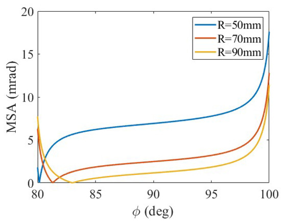
Figure 3.
The relationships between and MSA for different R.
Combined with the Bragg condition, changes in the period affect the spectral bandwidth derived from the Bragg condition. Furthermore, when correlated with Equation (5), the influence of period variations ultimately manifests in the filtering spectral bandwidth obtained after wavelength shift, thereby affecting the degree of dispersion of the spot on the image planar. Figure 4 illustrates the influence of the grating period on both MSA and spectral bandwidth. It is evident that reducing MSA requires the selection of a smaller period, which aligns with the need to decrease the filter bandwidth—specifically, a smaller period narrows the wavelength selectivity. This relationship underscores the critical role of period optimization in controlling grating dispersion. Smaller periods enable tighter spectral confinement, proving particularly valuable for applications demanding high-resolution discrimination between closely spaced wavelengths.
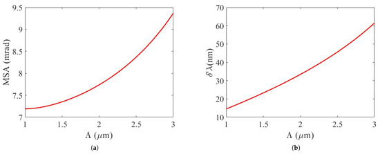
Figure 4.
Impact of period on MSA and filtering spectral bandwidth at a central wavelength of 550 nm. (a) The relationships between and MSA. (b) The relationships between and wavelength selective width.
Similarly, according to Equation (5), the influence of thickness variations ultimately manifests in the filtering spectral bandwidth obtained after wavelength shift, thereby affecting the degree of dispersion of the spot on the image planar. The influence of VBG thickness on MSA is shown in Figure 5a; thicker VBG exhibits narrower spectral width, according to Equation (5). An increase in thickness reduces the intrinsic wavelength-selective width of the VBG, as illustrated in Figure 5b, ultimately leading to a reduction in MSA.
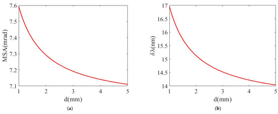
Figure 5.
Impact of Thickness on MSA and Filtering Spectral Bandwidth at a Central Wavelength of 550 nm. (a) The relationships between thickness d and MSA. (b) The relationships between thickness d and wavelength selective width.
To reduce the divergence angle of the incident beam and achieve a wider field of view, it is necessary to select an appropriate radius of curvature. Based on the Bragg condition and the inherent wavelength selectivity of VBG, this requires an optimal tilt angle, smaller period, and greater thickness.
Due to its wavelength-selective properties, a VBG diffracts light of different wavelengths at distinct incident angles that satisfy the Bragg condition. This results in varying propagation directions for different wavelengths after diffraction, causing dispersion that degrades spatial resolution. Common dispersion reduction methods include minimizing the incident light divergence angle [25], with an ideal target compression to the milliradian (mrad) level [20]. To validate the effectiveness of convex transmissive VBG in enhancing spatial resolution, we conducted a comparative analysis of the minimum spot area (MSA) between convex and planar transmissive VBG with identical structural parameters. In the optical path of the planar VBG, a convex lens matching the curvature radius of the convex VBG was employed. While the planar VBG receives diverging light transmitted through this lens, the convex VBG directly intercepts the beam originating from a pinhole aperture. Using specified grating parameters, the beam divergence angle incident on the planar VBG surface after passing through a 50 mm radius-of-curvature lens was measured at 6.6 mrad. In contrast, the external divergence angle for the convex transmissive VBG reached 179.6 mrad. The internal divergence angle within the convex VBG—a function correlated with the external divergence angle—exhibits minor variations due to deflection within the grating, with theoretical calculations estimating it at approximately 4.5 mrad. Meanwhile, the computed internal divergence angle for the planar VBG remained consistently between 4.17 and 4.20 mrad. Results demonstrate that the convex transmissive VBG reduces the beam divergence angle from 179.6 mrad to 4.5 mrad, effectively mitigating chromatic blur. Although the convex VBG exhibits a marginally larger internal divergence angle than its planar counterpart, resolution can be further enhanced by optimizing the vector tilt angle.
During diffraction-limited imaging with a fixed focal length f of the imaging lens, the Point Spread Function (PSF) was established to evaluate the imaging spatial resolution of the convex transmissive VBG.
As indicated by the blue curve in Figure 6a, the planar transmissive VBG achieves an average resolvable line pair density of 3.18 lps/mm. The red curve in Figure 6a shows that the convex transmissive VBG without vector tilt angle optimization yields 2.78 lps/mm. After optimizing the vector tilt angle to ϕ = 83° (light blue curve, Figure 6a), the convex VBG demonstrates significantly enhanced resolution at 3.80 lps/mm. These results confirm that the optimized convex VBG exhibits superior PSF performance across the visible spectrum compared to the planar VBG.
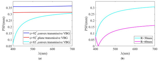
Figure 6.
Variation in the VBG’s PSF with incident wavelength. (a) Planar VBG vs. convex VBG with optimized vector tilt angle. (b) PSF before and after curvature radius compensation for vector tilt angle.
Figure 6b demonstrates that after varying the radius of curvature, the optimal value of the vector tilt angle can be determined from the position of the minimum MSA value, indicating a compensation effect between the curvature radius and optimal vector tilt angle. The pre-compensation PSF inflection point (light blue curve in Figure 6a/Figure 6b) initially occurs before 400 nm. Increasing the curvature radius shifts this inflection point to 413 nm while improving PSF performance throughout the visible band—consistent with the conclusions in Figure 2a.
Table 2 compares the average imaging resolution of transmissive VBG with different structural parameters. The results demonstrate that after optimizing solely the vector tilt angle, the convex transmissive VBG achieves a 16.31% higher average resolution than its planar counterpart. Through co-optimization of the vector tilt angle and curvature radius, spatial resolution is further enhanced by 61.31% compared to planar VBG.
Table 2.
Distinguishability of different transmissive VBG.
3. Experimental Results and Analysis
To validate the theoretical analysis in Table 2, an experimental setup (Figure 7 and Figure 8) was constructed using planar and convex transmissive VBG with identical pre-optimized structural parameters (Table 3) to compare theoretical and experimental spectral imaging performance. This verifies the convex VBG model’s accuracy while establishing an experimental foundation for investigating the vector tilt angle and curvature radius effects. The convex VBGs were fabricated via standard amplitude-splitting interferometry: coherent-beam-interference inscription in photosensitive media followed by convex surface machining and anti-reflection coating to complete tunable filter prototypes. System configuration included a commercial camera lens (with a large field of view to enhance alignment tolerance, 108 mm focal length), convex lens L1/convex VBG ( = 100 mm), and charge-coupled device (CCD)-front convex lens L2 ( = 50 mm). Object light formed a sharp real image at the camera’s rear focal planar; after divergence amplification, the focal-matched convex VBG collected and pre-collimated rays. Mounted on a 0.001°-precision rotation stage, the VBG enabled 0.1 nm spectral tuning through incident angle adjustment, diffracting Bragg-matched components to the CCD lens for imaging. Spectrometer substitution permitted direct filtering bandwidth measurement at the image planar.
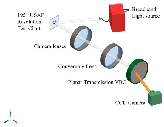
Figure 7.
Planar transmissive VBG based spectral imaging system. Converging lens: , ; CCD: .
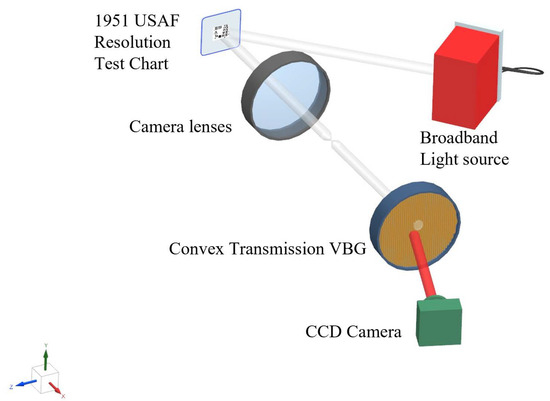
Figure 8.
Convex transmissive VBG based spectral imaging system. Convex transmissive VBG: ; CCD: .
Table 3.
Imaging resolution of planar vs. convex transmissive VBG on USAF-1951 reflective target at 624.8 nm.
The experiment employed a broad-spectrum halogen tungsten lamp to illuminate a USAF-1951 (which is come from Edmund Optics, Barrington, NJ, USA) resolution target, enabling calculation of the system’s line-pair resolution (inverse of the PSF) through identification of the finest resolvable element at the imaging planar. Spectral analysis and imaging of this diffuse-reflective target yielded empirically measured PSF values and full-width at half-maximum (FWHM) data for quantitative assessment of spatial resolution performance.
The USAF-1951 resolution target used in Figure 7 and Figure 8 is widely employed to evaluate the resolution capability of optical imaging systems (such as microscopes and cameras). Figure 9 presents the imaging results for both planar and convex transmissive VBG. Due to aberrations in the imaging system, the image quality at the edges is inferior to that at the center. The image of the resolution target obtained with the planar transmissive VBG (the red dashed box in Figure 9a) allows identification up to group (0), element (5), corresponding to a measured line pair density of 1.59 lps/mm. However, the imaging quality is significantly degraded across the wavelength tuning range due to pronounced stray interference fringes. In contrast, the image acquired with the convex transmissive VBG (the red dashed box in Figure 9b) resolves features up to group (1), element (3), corresponding to a measured line pair density of 2.52 lps/mm. This represents a mere 9% deviation from the theoretical value of 2.77 lps/mm.
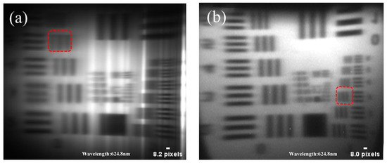
Figure 9.
Monochromatic images of USAF-1951 resolution target. (a) Planar transmissive VBG. (b) Convex transmissive VBG.
Compared to similar spectral imaging systems, the compressive sensing hyperspectral imaging system based on LCTF significantly improves spatial and spectral resolution; however, the system is relatively complex, suffers from light energy attenuation, and is susceptible to stray light. The CubeSat hyperspectral imager based on freeform optics suppresses stray light while maintaining high spatial resolution and achieves miniaturization of the imaging system, but its design and manufacturing present certain challenges. The four common optical schemes based on AOTF require trade-offs among different key parameters: for instance, T-coll and D-coll offer high spectral resolution but suffer severe light loss, whereas S-coll provides high spectral resolution but exhibits significant chromatic shift, and S-conf cannot simultaneously achieve both high spatial resolution and high spectral resolution [26,27,28]. Compared to the planar VBG, the convex VBG achieves a 37% improvement in the measured resolution. Furthermore, imaging with the convex transmissive VBG is free from stray interference fringes, resulting in significantly superior image quality over the planar structure.
To investigate the image quality issues associated with planar transmissive VBG, the focal length of lens L1 was adjusted to 50 mm in the experiment. The stray light patterns produced by planar transmissive VBGs with different structural parameters were then compared, as shown in Figure 10. The grating parameters in Figure 10a are identical to those in Figure 9a, while the parameters for Figure 10b are listed in Table 4. The experimental results demonstrate that stray interference fringes originating from the VBG itself are present in planar transmissive VBGs with both sets of structural parameters, indicating that the generation of such fringes is independent of the grating’s structural parameters. In contrast, no stray light phenomena were observed in the imaging results obtained with the convex transmissive VBG. This occurs because light reflected from the rear surface of the planar VBG interferes with light reflected from the front surface, generating unintended stray fringes.
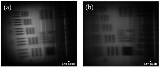
Table 4.
Parameters of planar VBG corresponding to Figure 10b.
At the central wavelength indicated in Figure 9, spectral measurements were performed on the image planar of the spectral imaging system. In Figure 11, the red curve represents the measured data, while the black curve denotes the fitted result. Experimental data reveal that the spectral tuning range of the planar VBG is approximately 598–663 nm, while that of the convex VBG is approximately 600–630 nm. The planar transmissive VBG exhibits a filter FWHM of 28.42 nm (Figure 11a). In contrast, the convex transmissive VBG achieves a significantly narrower FWHM of 17.37 nm (Figure 11b), representing a 63.6% reduction in spectral bandwidth. Furthermore, the spectral distribution of the convex VBG more closely approximates a Gaussian profile. (The fitting was performed over the 550–700 nm range, resulting in an increase in R2 from 0.90 to 0.93.) This observation further validates the performance advantage of the convex VBG structure in spectral selectivity.
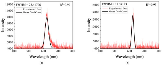
Figure 11.
The planar and convex FWHM of VBG. (a) Planar transmissive VBG: 28.42 nm. (b) Convex transmissive VBG: 17.37 nm.
As can be seen from Table 5, from a theoretical perspective, the convex VBG obtained by optimizing the curvature radius and vector tilt angle (In Figure 1, represents the vector tilt angle. After optimization, was adjusted from 92° to 83°), which demonstrates improvements in both spatial and spectral resolution compared to a planar VBG. From an experimental standpoint, optimizing only the curvature radius can also enhance the spatial and spectral resolution of the VBG. (The convex surface was achieved through front-surface machining of the VBG, with the physical prototype shown in Figure 12).
Table 5.
Summary table: spatial and spectral resolution comparison of planar vs. convex transmissive VBG (theoretical and experimental) with optimized curvature radius and vector tilt angle.
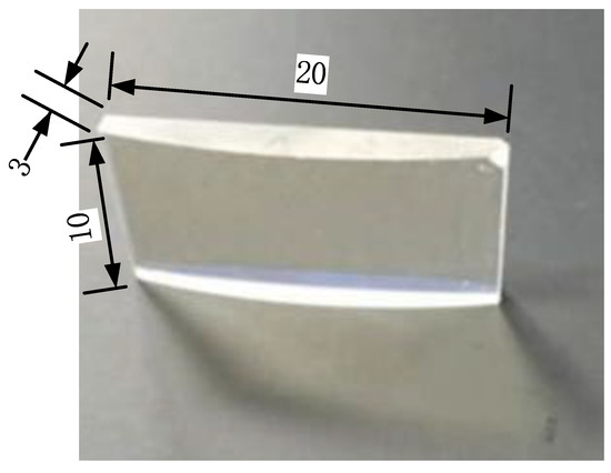
Figure 12.
Physical prototype of the convex VBG.
4. Conclusions
A new high-resolution spectral imaging component called convex transmissive VBG is designed in this paper. The filtered imaging model is established for describing the convex transmissive VBG. Two majority parameters, the curvature radius and vector tilt angle, are most important parameters affecting the resolution. Furthermore, a coupling relationship between curvature and the vector tilt angle is established, revealing that curvature affects the MSA by the divergence angle, while the vector tilt angle affects the MSA by the Bragg Condition.
The preferred method of the curvature radius and VTA was established and verified experimentally. The MSA was also introduced to characterize the degree of image planar dispersion, thereby optimizing and fabricating sample gratings with improved spatial and spectral resolution. The experimental results demonstrate that, with identical structural parameters, the imaging quality and spectral resolution of convex transmissive VBG surpass planar transmissive VBG by 58.5% and 63.6%, which closely matches theoretical predictions.
The method proposed in this paper can promote the development of miniaturized VBG spectral imaging systems, as increasing the radius of the curvature parameter can significantly reduce the complexity of the front-end optical system design. However, as this is a newly designed component, a phase difference exists in different optical axes. Due to factors such as manufacturing processes, the theoretical optimum value has not yet been achieved for the current sample. This must be accomplished in the next stage of the research.
Author Contributions
Conceptualization, Y.L. (Yueying Li) and J.D.; methodology, Y.L. (Yueying Li); software, Y.L. (Yueying Li); validation, X.Z. and Y.C.; formal analysis, Y.L. (Yueying Li); investigation, Y.L. (Yueying Li) and Y.P.; resources, Y.L. (Yueying Li), J.D. and D.Z.; data curation, Y.L. (Yueying Li); writing—original draft preparation, Y.L. (Yongquan Luo) and X.Z.; writing—review and editing, Y.L. (Yueying Li); visualization, Y.L. (Yueying Li); supervision, J.D.; project administration, Y.L. (Yongquan Luo) and D.Z.; funding acquisition, J.D. All authors have read and agreed to the published version of the manuscript.
Funding
This research was funded by National Natural Science Foundation grant number 61805224 and 61905229. This research was also funded by a certain innovative project with the number “C90202525”.
Institutional Review Board Statement
Not applicable.
Informed Consent Statement
Not applicable.
Data Availability Statement
The data presented in this study are available on request from the corresponding author.
Conflicts of Interest
The authors declare no conflicts of interest.
Abbreviations
The following abbreviations are used in this manuscript:
| VBG | Volume Bragg Grating |
| FOV | Field of View |
| AOTF | Acousto-Optic Tunable Filters |
| LCTF | Liquid Crystal Tunable Filters |
| MSA | Maximal Splitting Angle |
| PSF | Point Spread Function |
| CCD | Charge-Coupled Device |
| FWHM | Full-Width at Half-Maximum |
References
- Ahmadi, A.; Mosallaei, H. The image performance of a negative index slab and a layered slab using coupled surface modes. J. Appl. Phys. 2009, 106, 064502. [Google Scholar] [CrossRef]
- Fang, L.; Jiang, Y.; Yan, Y.; Yue, J.; Deng, Y. Hyperspectral Image Instance Segmentation Using Spectral–Spatial Feature Pyramid Network. IEEE Trans. Geosci. Remote Sens. 2023, 61, 1–13. [Google Scholar] [CrossRef]
- Wang, Z.; Zhou, J.; Liu, S.; Li, M.; Zhang, X.; Huang, Z.; Dong, W.; Ma, J.; Ai, L. A Land Surface Temperature Retrieval Method for UAV Broadband Thermal Imager Data. IEEE Geosci. Remote Sens. Lett. 2022, 19, 1–5. [Google Scholar] [CrossRef]
- Zhou, T.-D.; Liang, X.-B.; Li, C.; Huang, Z.-H.; Feng, J.-S.; Zhao, L.; Wang, J.-J.; Jing, F. 2.5 kW average power, two-channel spectral-beam-combined output based on transmitting volume Bragg grating. Acta Phys. Sincia 2017, 66, 084204. [Google Scholar] [CrossRef]
- Drachenberg, D.R.; Andrusyak, O.; Cohanoschi, I.; Divliansky, I.; Mokhun, O.; Podvyaznyy, A.; Smirnov, V.; Venus, G.B.; Glebov, L.B. Thermal tuning of volume Bragg gratings for high power spectral beam combining. In Proceedings of the Fiber Lasers VII: Technology, Systems, and Applications, San Francisco, CA, USA, 25–28 January 2010; Tankala, K., Ed.; International Society for Optics and Photonics, SPIE: Bellingham, WA, USA, 2010; Volume 7580, p. 75801U. [Google Scholar] [CrossRef]
- Song, J.H.; Kwon, Y.H. Hyperspectral push-broom imager using a volume Bragg grating as an angular filter. Opt. Express 2024, 32, 8736–8750. [Google Scholar] [CrossRef]
- Dumke, I.; Nornes, S.M.; Purser, A.; Marcon, Y.; Ludvigsen, M.; Ellefmo, S.L.; Johnsen, G.; Søreide, F. First hyperspectral imaging survey of the deep seafloor: High-resolution mapping of manganese nodules. Remote Sens. Environ. 2018, 209, 19–30. [Google Scholar] [CrossRef]
- Guerri, M.F.; Distante, C.; Spagnolo, P.; Bougourzi, F.; Taleb-Ahmed, A. Deep learning techniques for hyperspectral image analysis in agriculture: A review. ISPRS Open J. Photogramm. Remote Sens. 2024, 12, 100062. [Google Scholar] [CrossRef]
- Shitharth, S.; Manoharan, H.; Alshareef, A.M.; Yafoz, A.; Alkhiri, H.; Mirza, O.M. Hyper spectral image classifications for monitoring harvests in agriculture using fly optimization algorithm. Comput. Electr. Eng. 2022, 103, 108400. [Google Scholar] [CrossRef]
- Sandasi, M.; Vermaak, I.; Chen, W.; Viljoen, A.M. Hyperspectral Imaging and Chemometric Modeling of Echinacea—A Novel Approach in the Quality Control of Herbal Medicines. Molecules 2014, 19, 13104–13121. [Google Scholar] [CrossRef]
- Payne, G.; Langlois, N.; Lennard, C.; Roux, C. Applying visible hyperspectral (chemical) imaging to estimate the age of bruises. Med. Sci. Law 2007, 47, 225–232. [Google Scholar] [CrossRef]
- Arablouei, R.; Goan, E.; Gensemer, S.; Kusy, B. Fast and robust pushbroom hyperspectral imaging via DMD-based scanning. arXiv 2016, arXiv:1608.00361. [Google Scholar] [CrossRef]
- Zhang, C.; Wang, H.; Zhang, Z.; Yuan, J.; Shi, L.; Sheng, Z.; Zhang, X. Narrowband double-filtering hyperspectral imaging based on a single AOTF. Opt. Lett. 2018, 43, 2126–2129. [Google Scholar] [CrossRef]
- Yuan, J.; Fan, W.; Cheng, H.; Huang, D.; Du, T. Interference Spectral Imaging Based on Liquid Crystal Relaxation and Its Application in Optical Component Defect Detection. Appl. Sci. 2022, 12, 718. [Google Scholar] [CrossRef]
- Wang, Y.; Tong, G.; Li, B.; Guo, X.; Song, X.; Zhao, Y.; Karim, S.; Deng, C.; Zhou, J.; Zhang, W.; et al. Miniaturized customized filtering-wheel-based multispectral imaging system for target detection. Measurement 2023, 221, 113506. [Google Scholar] [CrossRef]
- Kogelnik, H. Coupled wave theory for thick hologram gratings. Bell Syst. Tech. J. 1969, 48, 2909–2947. [Google Scholar] [CrossRef]
- Ludman, J.; Riccobono, J.R.; Reinhand, N.O.; Korzinin, Y.L.; Semenova, I.; Shahriar, S.M. Nonspatial filter for laser beams. Quantum Electron. 1996, 26, 1093–1096. [Google Scholar] [CrossRef]
- Henrion, M.; Ludman, J.E.; Sobolev, G.A.; Shahriar, M.S.; Soboleva, S.B.; Hemmer, P.L. Two-dimensional holographic nonspatial filtering for laser beams. In Proceedings of the Photopolymer Device Physics, Chemistry, and Applications IV, Online, 15–16 July 1998. [Google Scholar] [CrossRef]
- Ott, D.; SeGall, M.; Divliansky, I.; Venus, G.; Glebov, L. High-contrast filtering by multipass diffraction between paired volume Bragg gratings. Appl. Opt. 2015, 54, 9065. [Google Scholar] [CrossRef]
- Blais-Ouellette, S.; Daigle, O.; Taylor, K. The imaging Bragg tunable filter: A new path to integral field spectroscopy and narrow band imaging. In Proceedings of the Ground-based and Airborne Instrumentation for Astronomy, Orlando, FL, USA, 25–29 May 2006. [Google Scholar] [CrossRef]
- Duan, J.; Zhao, X.; Hu, Q.; Wu, F.; Luo, Y.; Zhang, D. Volume Bragg grating filters and its spectral imaging application. High Power Laser Part. Beams 2018, 30, 079001-1. [Google Scholar] [CrossRef]
- Havermeyer, F.; Liu, W.; Moser, C.; Psaltis, D.; Steckman, G.J. Volume holographic grating-based continuously tunable optical filter. Opt. Eng. 2004, 43, 2017–2021. [Google Scholar] [CrossRef][Green Version]
- Duan, J.; Zhao, X.; Luo, Y.; Zhang, D. Improving the spatial resolution of volume Bragg grating two-dimensional monochromatic images. Appl. Opt. 2018, 57, 3159. [Google Scholar] [CrossRef] [PubMed]
- Eckhard, J.; Eckhard, T.; Valero, E.M.; Nieves, J.L.; Contreras, E.G. Outdoor scene reflectance measurements using a Bragg-grating-based hyperspectral imager. Appl. Opt. 2015, 54, D15–D24. [Google Scholar] [CrossRef]
- Chakraborty, D.; Georgiev, R.; Aspell, S.; Toal, V.; Naydenova, I.; Cody, D.; Martin, S. Modelling and Design of Holographic Optical Elements for Beam-Coupling Applications for a Range of Incident Beam Angles. Photonics 2022, 9, 936. [Google Scholar] [CrossRef]
- Xi, W.; Zhang, Y.; Ma, X.; Xu, T.; Arce, G. Compressive spectral imaging system based on liquid crystal tunable filter. Opt. Express 2018, 26, 25226–25243. [Google Scholar] [CrossRef] [PubMed]
- Liu, Y.; Bauer, A.; Viard, T.; Rolland, J. Freeform hyperspectral imager design in a CubeSat format. Opt. Express 2021, 29, 35915–35928. [Google Scholar] [CrossRef]
- Batshev, V.; Machikhin, A.; Gorevoy, A.; Martynov, G.; Khokhlov, D.; Boritko, S.; Pozhar, V.; Lomonov, V. Spectral Imaging Experiments with Various Optical Schemes Based on the Same AOTF. Materials 2021, 14, 2984. [Google Scholar] [CrossRef]


Disclaimer/Publisher’s Note: The statements, opinions and data contained in all publications are solely those of the individual author(s) and contributor(s) and not of MDPI and/or the editor(s). MDPI and/or the editor(s) disclaim responsibility for any injury to people or property resulting from any ideas, methods, instructions or products referred to in the content. |
© 2025 by the authors. Licensee MDPI, Basel, Switzerland. This article is an open access article distributed under the terms and conditions of the Creative Commons Attribution (CC BY) license (https://creativecommons.org/licenses/by/4.0/).