2. Basic Theoretical Formulae
Let us consider the situation presented in
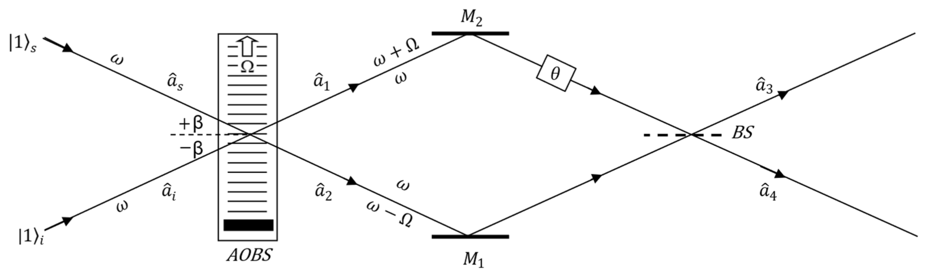
Figure 1 when two coherent light beams are incident symmetrically on a plane sinusoidal ultrasonic wave at positive and negative Bragg angle β. The problem of the interaction of two coherent light beams with ultrasonic wave was studied theoretically by Leroy and Blomme [
8] in 1984. The light beams were incident on an ultrasonic wave at positive and negative Bragg angle.
For the Bragg regime [
9], the light beams, after passing through the ultrasonic wave, create only two diffraction orders: plus and minus the first diffraction order [
8]. A positive first diffraction order is formed when light is incident at a positive Bragg angle β on the ultrasonic wave. However, when light is incident at a negative Bragg angle β on an ultrasonic wave, we obtain a negative first diffraction order. When light is simultaneously incident at positive and negative Bragg angles, the direction of the zero-diffraction order originating from the beam incident at the negative Bragg angle coincides with the direction plus the first diffraction order of the beam incident at the positive Bragg angle onto the ultrasonic wave. Similarly, the direction of the negative first diffraction order coincides with the direction of the zero diffraction order of the beam of light incident at a positive Bragg angle. Because of the overlapping directions of the diffraction orders, we observed only two diffraction orders instead of four. The directions of these two diffraction orders corresponded to the positive and negative directions of the first diffraction order, respectively. The theoretical predictions of Leroy and Blomme [
8] were experimentally confirmed in 2019 [
10] and extended to include the influence of the initial phase of the ultrasonic waves. From the solution of the Raman–Nath [
11] equations modified by Mertens [
12] with the initial phase of the ultrasonic wave, we obtain the following form of the amplitudes of light diffracted on the ultrasonic wave [
7,
10]:
where the amplitudes of the diffracted light
and
describe the zero order plus the first diffraction order (1a) coming from the light beam incident on the ultrasonic wave at the positive Bragg angle. The amplitudes of the diffracted light
and
describe the zero order and negative first diffraction order (1b) coming from the light beam incident on the ultrasonic wave at the negative Bragg angle.
The amplitude of the diffracted light on the ultrasonic wave depends on the Raman–Nath parameter
, which is proportional to the amplitude of the changes in the refractive index
caused by the ultrasonic wave, and is expressed by the following formula:
where
is the wavelength of light, and
l is the width of the ultrasonic wave.
Further analysis of the interaction of two coherent light beams with ultrasonic wave requires consideration of the fact that the frequency of light diffracted to the +1-st diffraction order is increased by the frequency of the ultrasonic wave owing to the Doppler effect, that is, ω + Ω. In contrast, the light diffracted to −1-st order has a decreased frequency by the frequency of the ultrasonic wave ω − Ω. However, the frequency of light in the zero diffraction order is unchanged and equal to the frequency of light incident at the positive and negative Bragg angles on the ultrasonic wave. The diffraction orders, amplitudes, and frequencies are shown in
Figure 1.
When two coherent light beams are simultaneously incident on the ultrasonic wave at positive and negative Bragg angles, the presence of light with both changed and unchanged frequencies in a specific diffraction order results in the modulation of light intensity over time due to interference. This phenomenon of beats was predicted theoretically [
8] and recently confirmed experimentally [
10].
where
is the phase shift between incident light beams on the ultrasonic wave.
The last formulas shows that the intensity of light in the ±1-st diffraction order is modulated in time with the angular frequency Ω of the ultrasonic wave. Modulation in the positive first diffraction order is always 180° out of phase relative to the light intensity modulation in the negative first diffraction order regardless of the phase difference between the incident light waves Φ on the ultrasonic beam and the initial phase of the ultrasonic wave δ.
A completely different result is obtained when instead of two coherent light beams falling at positive and negative Bragg angles on the ultrasonic wave, two indistinguishable single photons are incident on the ultrasonic wave. In this case, the ultrasonic wave acts as an acousto-optical beam splitter (
AOBS), which can be, as mentioned earlier, classified as an active beam splitter [
6]. In the rest of the text, we refer to an ultrasonic wave as either an ultrasonic beam or an acousto-optical beam splitter (
AOBS).
Considering that the Doppler effect changes the frequency of photons that are diffracted on an ultrasonic beam to the ±1-st diffraction order and the previously determined probability amplitudes (1a) and (1b) of photon diffraction on an acousto-optical beam splitter (
AOBS), the following relations exist between the operators at the output and input of the acousto-optical beam splitter:
where
and
denote the photon annihilation operators at the input ports of the acousto-optical beam splitter (
AOBS) and
and
represent the photon annihilation operators at the outputs of the acousto-optical beam splitter. Formulas (4a) and (4b) were found earlier in a study of the interaction of the two-photon NOON state with ultrasonic wave [
7]. These formulas differ fundamentally from the formulas given by Zilinger’s group [
5] because Equation (4a) and (4b) consider the Doppler shift on the ultrasonic wave.
Using the above relations between operators, we can calculate the probability of detecting a photon in the 0-th and +1-st diffraction order when a single photon is incident on an ultrasonic wave at a positive Bragg angle and the second input is in a vacuum state. In this case, the state at the input of the acousto-optical beam splitter can be written in the form
and we can calculate the probabilities of photon detection in the 0-th and +1-st diffraction order in the following form:
where
and
denote photon creation operators.
However, for case
, when a single photon falls on the ultrasonic wave at a negative Bragg angle and the second input is in a vacuum state, the probabilities of photon detection in 0-th and −1-st diffraction order are expressed by (6).
The above results (5) and (6) are identical to the classical solutions [
9] for a single light wave incident at positive and negative Bragg angle on an ultrasonic wave.
When single photons are simultaneously injected into the two input ports of the acousto-optical beam splitter (
AOBS), the incident state is
and the probability of detecting photons in the plus first and minus first diffraction orders is determined by the following formula:
The last formula shows that the probability of detecting a photon in the ±1-st diffraction order does not depend on time, the Raman–Nath parameter, or the initial phase δ of the ultrasonic wave. Therefore, in this case, we do not observe modulation in the time of the number of photons in the ±1-st diffraction order, as it was for two coherent light beams falling on the acousto-optical beam splitter at positive and negative Bragg angles (3a) and (3b).
However, when single photons are injected simultaneously into the two input ports of the acousto-optical beam splitter (
AOBS), the probability of detecting coincidences of photons between the plus first and minus first diffraction orders is described by (8).
It should be emphasized that the same formula for the coincidence of photons between the +1-st and −1-st diffraction orders was obtained by the Zeilinger group [
5], despite neglecting the influence of the Doppler effect introduced by the ultrasonic wave. Although the Doppler effect does not affect the coincidence of photons between diffraction orders, it changes the frequency of two-photon states, as shown below.
For the value of the Raman–Nath parameter
the probability of detecting coincidences of photons between the plus first and minus first diffraction orders decreases to zero, and the dependencies between the operators at the output and input of the acousto-optical beam splitter (4a) and (4b) take the following form:
From the above Formulas (9a) and (9b), it follows that for the Raman–Nath parameter v = π/2 the acousto-optical beam splitter behaves like a lossless 50:50 beam splitter.
Again, let us consider a situation in which single photons are simultaneously injected into the two input ports of the 50:50 acousto-optical beam splitter. Then, the incident state is
which can be written as:
For the acousto-optical beam splitter (
AOBS) described by (9a) and (9b), we obtain the photon creation operators
and
in the following form:
Using the creation operators
and
we can examine the state of photons at the output of the acousto-optical beam splitter.
The result obtained in formula (11) is very similar to the result describing the Hong–Ou–Mandel interferometer, with the difference that the frequency of the two-photon state in the positive diffraction order is increased by the frequency of the ultrasonic wave, and in the negative diffraction order, it is reduced by the frequency of the ultrasonic wave. It is easy to verify that the sum of the photon energies at the input of the acousto-optical beam splitter is equal to the sum of the photon energies at the output of the acousto-optical beam splitter. It should be emphasized that there are no states
in the output, which disappear as a result of Hong–Ou–Mandel interference; consequently, the probability of detecting coincidences of photons between the +1-st and −1-st diffraction orders is zero, as it occurs in the Hong–Ou–Mandel interferometer. The confirmation of the frequency difference in the two-photon states at the outputs of the acousto-optical beam splitter is only possible in the interference process because of their small frequency difference, which is equal to twice the frequency of the ultrasonic wave. The interference process can be realized by introducing an additional optical beam splitter to the measuring system. A schematic of the measuring system that enables detection of the frequency difference in the two-photon states between the outputs of the acousto-optical beam splitter is shown in
Figure 2. The experimental setup resembles a Mach–Zehnder interferometer, where the input beam splitter is replaced by an ultrasonic wave. Thirty-five years ago, Ou, Zou, Wang, and Mandel [
13] discovered fourth-order interference in a Mach–Zehnder interferometer and compared it with classical second-order interference. The examination of second- and fourth-order interference in a Mach–Zehnder interferometer, in which the input beam splitter was replaced by an ultrasonic wave, will allow us to examine the influence of the Doppler shift on two-photon states arising from the interference of Hong–Ou–Mandel on an acousto-optical beam splitter.
Let us assume that the output beam splitter (
BS) from the interferometer is a lossless 50:50 optical beam splitter with the reflected beam suffering a
phase shift. For such an optical beam splitter, the output and input modes [
14] are related by the following relationships.
where
and
are the photon annihilation operators at the inputs of the beam splitter (
BS); while
and
are at the outputs of the beam splitter; and
is the relative phase shift between the interferometer arms. After substituting
and
in the form of (4a) and (4b) into the last Formulas (12a) and (12b), we obtain the following expressions:
The above equations allow the calculation of the probability of photon detection at the outputs from the optical beam splitter (BS), or the probability of detecting coincidences of photons between the outputs of the optical beam splitter (BS), that is, at the interferometer outputs, depending on the state of the photons at the interferometer inputs.
First, we examine the case of second-order interference, which occurs when single photons are incident on only one of the inputs of the acousto-optical beam splitter (
AOBS) and the other input is in a vacuum state. In this case, the single-photon input state can be written in the form
. Using formulas (13a) and (13b), we can calculate the probabilities of photon detection at the outputs from the optical beam splitter (
BS) in the following form:
The last formulas show that the probability of detecting photons at the outputs of an optical beam splitter (BS) changes periodically with the angular frequency Ω of the ultrasonic wave, and the amplitude of these changes depends on the Raman–Nath parameter. For the Raman–Nath parameter v = π/2, the modulation depth reaches a value 100 percent and the acousto-optical beam splitter behaves like a 50:50 beam splitter as can be deduced from formulas (9a) and (9b).
For the case when the Raman–Nath parameter
v =
π/2 and single photons are injected simultaneously into the two input ports of the acousto-optical beam splitter (
AOBS), we can calculate using formulas (13a) and (13b) the probabilities of detecting photons at the outputs from the optical beam splitter (
BS). For the input state in the form
, the second-order interference disappears and from formulas (13a) and (13b), we obtain the following expressions:
It is clear from the last formulas that the probabilities of detecting a photon at the outputs from the optical beam splitter (
BS), which are also the outputs from the interferometer, are equal to one and do not depend on the time, phase shift θ, or initial phase δ of the ultrasonic wave. Such dependencies appear only for the coincidence of photons between the outputs of an optical beam splitter (
BS). Using formulas (13a) and (13b) for the input state in the form
we can calculate the coincidence of photons between the interferometer outputs.
For the fourth-order interference described by Equation (16), the number of coincidence counts changes periodically in time with a frequency equal to twice the frequency of the ultrasonic wave, that is, twice the frequency of that in the case of second-order interference (14a) and (14b). In addition, the dependence on phases θ and δ changes twice as quickly as for the second-order interference (14a) and (14b). It should be emphasized that the modulation depth, unlike second-order interference, does not depend on the Raman–Nath parameter and is always 100 percent. The Raman–Nath parameter influences only the modulation amplitude, which achieves its first maximum at
v =
π/2. At this value of
v =
π/2, the acousto-optical beam splitter functions as a 50:50 beam splitter, as demonstrated by formulas (9a) and (9b). The two-photon beat phenomenon, which has a frequency twice that of the ultrasonic wave, results from the Doppler effect. When we neglect the Doppler effect (Ω = 0) and the initial phase of the ultrasonic wave (δ = 0) in formula (16), for the Raman–Nath parameter
v =
π/2, we obtain the well-known formulas for fourth-order interference discovered by Ou, Zou, Wang and Mandel [
13] in the Mach–Zehnder interferometer:
together with the previously derived formulas (15a) and (15b).
Equations (14)–(16) for the Mach–Zehnder interferometer in which the input beam splitter was replaced by an ultrasonic wave (
Figure 2) were identical to those for the Mach–Zehnder interferometer in which the output beam splitter was replaced by an ultrasonic wave [
7].
3. Experimental Setup
Figure 3 shows a scheme of the experimental arrangement developed for the investigation of Hong–Ou–Mandel interference on the acousto-optical beam splitter, together with a scheme of a system for measuring the phenomenon of single- and two-photon beats caused by the Doppler effect on the ultrasonic wave.
The optical part of the measuring system is based on fiber-optic technology, which significantly facilitates adjustment and calibration of the measuring system. The system is based on single-mode fibers and single-mode polarization-maintaining fibers, which ensure a constant photon polarization direction. An optical beam splitter was also fabricated using the single-mode polarization-maintaining fiber technique.
The optical fibers were finished using adjustable collimators mounted on a high-quality kinematic optical mount (7 mrad/rev). These high-quality kinematic optical mounts ensured the precise positioning of the collimators at Bragg angles (7 mrad) and diffraction angles.
An important element in facilitating the initial adjustment and calibration of the measurement system is the use of an additional laser diode that generates infrared light with a wavelength (810 nm), which is equal to the wavelength of the photon pairs. Light from the laser was observed under night vision. Therefore, it was possible to quickly perform an initial adjustment and calibration of the measuring system and detect imperfections in the optical system. Moreover, when the laser diode was below the threshold value, it allowed the quick determination of the position of the (C
4) or (C
7) collimator, for which the optical paths of the light beams falling on the ultrasonic wave or beam splitter were equal. The concept of using a laser operating below the threshold value to test the optical path difference was described in [
7]. The light beam from the infrared laser (810 nm) was directed through the single-mode optical fiber (SM1) and collimators (C
1) and (C
2) to the single-mode polarization-maintaining optical fiber (PM1), whose task was to direct the light to the ultrasonic wave at a positive Bragg angle. The output of the polarization-maintaining fiber ended with a collimator of light (C
5), which ensured a homogeneous distribution of the intensity of the light beam originating from the collimator and a constant direction of light polarization. The laser beam created in this manner was directed through the prism (P
1) and fell exactly at a positive Bragg angle on an acousto-optical beam splitter (
AOBS) based on a progressive ultrasonic wave propagating in a water tank. Water as an acousto-optical medium excludes the appearance of polarization effects in an acousto-optical beam splitter. An ultrasonic wave of 32,370 MHz was radiated by a circular transducer (T) of 22.4 mm diameter made of a lithium niobate crystal (LiNbO
3). Additional information regarding the transducer and water tank has been provided in previous studies [
7,
15]. The light from the laser generating the infrared beam was directed to the ultrasonic wave at a negative Bragg angle using collimators (C
3) and (C
4), an optical fiber (PM2), and a prism (P
2). (In the scheme of the measuring system, the optical fiber with the collimator directing the infrared light beam to the collimator (C
3) has been omitted to simplify the drawing). The beams of light diffracted by the ultrasonic wave were directed to collimators (C
6) and (C
7) and from them to single-mode optical fibers (SM2) and (SM3) using prisms (P
3) and (P
4). The light from the optical fibers was measured using a fiber-optic power meter (model PM20 from Thorlabs; Newton, NJ, USA). By measuring the light power at the output of the optical fibers (SM2) and (SM3), the measurement system could be pre-adjusted, and the Raman–Nath parameter was pre-determined. Fine adjustment and calibration of the Raman–Nath parameter were performed on pairs of photons. A beta barium borate (BBO) crystal was used to generate photon pairs via type-1 parametric down-conversion [
14]. The source of the photon pairs was pumped using an InGaN laser diode (model LBX-405-100 from Oxxius; F-22300 Lannion, France). The wavelength of light from the laser was 405 nm and its power was 66 mW. A detailed description of the source of the photon pairs and the role of the individual elements of the source (G
1, G
2 and L) are described in [
7]. It should be mentioned that by placing the (C
1) collimator in the precise translation stage, it is possible to choose light from an infrared laser or photons from the source of the photon pairs. An analogous system with a collimator on a precise translating stage (in the measurement system) allows photons to be directed to the (C
3) collimator either from the infrared laser or from the source of the photon pairs. After diffraction on the ultrasonic wave and passing through the set of two filters (F), the photon pairs were directed by single-mode optical fibers (SM2) and (SM3) to single-photon counting modules (SPCM model AQ4C from Perkin-Elmer; Shelton, CT, USA). For this model, we have the following parameters: the maximum dark count rate is no more than 500 counts per second, dead time is 50 ns and pulse width is 30 ns. The set of two filters (F), long-pass and band-pass, passes only photons of 810 nm wavelength with a 10 nm bandwidth (FWHM). Photons detected by (SPCMs) were converted into electrical pulses, which after passing through a coincidence unit with a coincidence window of 22 ns, were registered by a dual-channel photon counter (SR 400) or by the Pico Quant PC-board model Time Harp 100; Berlin, Germany. The PC-board using the time-correlated single-photon counting (TCSPC) method recorded changes in time with 640 ps time resolution, number of photons, and number of their coincidences. The amplifier (model 325LA from ENI; Rochester, NY, USA) supplying the ultrasonic transducer (T) and the PC board were controlled by the same generator (model PM 5193 from Philips; 5611 Eindhoven, The Netherlands), which ensured a constant phase shift between the electrical signals supplying the ultrasonic transducer and the electrical pulses that synchronized the (TCSPC) electronics [
7]. It should be emphasized that the time-correlated single-photon counting method [
16] allows for the examination of light intensity changes using light detectors whose dead time or pulse width is greater than the period of the phenomenon being examined.
4. Experimental Investigation and Results
The diffraction of light on the ultrasonic wave is fully determined by two parameters: the Raman–Nath parameter, the Klein–Cook parameter, and the angle of incidence of the light beam on the ultrasonic wave. The Raman–Nath parameter is given by Equation (2), and the Klein–Cook parameter Q is defined by the following formula:
where Λ is the ultrasonic wavelength,
is the wavelength of the light wave in a vacuum,
is the refractive index of the acousto-optic medium,
l is the width of the ultrasonic beam. Experimental studies were carried out for the following parameters: ultrasonic wave length
, light wave length
, refractive index
, width of the ultrasonic beam
. For these values, the calculated Klein–Cook Q parameter was approximately 42; that is, when light falls on the ultrasonic wave at the Bragg angle, the Bragg regime condition is fulfilled. For this regime, the light intensity or the number of photons in the diffraction orders are described by classic Formulas (5) and (6). It allows the calibration of the Raman–Nath parameter by fitting theoretical curves to experimental curves. Experimental curves were obtained by measuring the number of photons in the diffraction order as a function of the voltage supplied to the ultrasonic wave transducer (the Raman–Nath parameter is proportional to the voltage supplying the ultrasonic wave transducer). When the angle of incidence of photons on the ultrasonic wave is exactly equal to the Bragg angle, the zero order intersects with the first order in the middle of the maximum value of the number of photons in the zero order and the intersection of the diffraction orders occurs exactly for the Raman–Nath parameter
v =
π/2.
Figure 4a shows the results of the calibration of the Raman–Nath parameter for zero and minus the first diffraction order. When single photons are incident simultaneously on two input ports of an acousto-optical beam splitter (
AOBS), then the input state can be written as
. The probability of detecting coincidences of photons between the plus first and minus first diffraction orders is described by (8).
Figure 4b shows the coincidence of photons between the plus first and minus first diffraction orders as a function of the Raman–Nath parameter.
Experimental data were corrected for the number of accidental coincidence counts measured previously. Remembering that for the Poisson statistic the uncertainty
in the number of photon counts depends on the square root (
) of the number of photon counts
, we can easily calculate the error at any measurement point. At the point of intersection of the curves in
Figure 4a, the number of photon counts is 16,100, which gives a measurement error of about 0.8%. It should be emphasized that the further measurement results depend significantly on the calibration of the Raman–Nath parameter. The data were corrected for accidental coincidences
, which we can estimate from the following relationship:
where
and
represent the counts of uncorrelated single events at the first and second inputs of the coincidence unit, respectively, and
denotes the width of the coincidence window. The numbers
and
also contain dark counts. The second option is the precise measurement of accidental counts. In this work, the number of accidental counts was experimentally determined, which is a better solution than calculating from formula (19).
The acousto-optic beam splitter behaves as a 50:50 beam splitter for the Raman–Nath parameter v = π/2, as shown by Equation (9a) and (9b). For this parameter, the Hong–Ou–Mandel (11) interference on the ultrasonic beam could be observed.
Figure 5 illustrates the Hong–Ou–Mandel effect observed when varying the optical path differences between the incident photons (
−
) on the ultrasonic beam, achieved by moving the collimator (C
4) along the optical path. The theoretical curve [
14] of coincident detections,
, has the form
where ∆ω represents the bandwidth of the light, and
and
denote the distances traveled by the signal and idler photons, respectively, from the down-converter crystal to the acousto-optical beam splitter (
AOBS). As shown in the experimental data in
Figure 5, the number of coincidence counts did not reach zero. Theoretically, the number of coincidence counts drops to zero, but in practice it is close to zero. Hence, a value called the visibility of the Hong–Ou–Mandel dip is introduced, which in this case is 95% (for zero coincidences, visibility is 100%).
In the theoretical part of this study, it was shown (11) that the frequency of the two-photon state in the positive diffraction order is increased by the frequency of the ultrasonic wave, whereas in the negative diffraction order, it is reduced by the frequency of the ultrasonic wave. The confirmation of the frequency difference between the two-photon states at the outputs of the acousto-optical beam splitter requires the use of an additional optical beam splitter. As shown in the scheme of the experimental setup (
Figure 3), the output fibers (SM2 and SM3) from the acousto-optical beam splitter were replaced with a single-mode polarization-maintaining fiber optical beam splitter (
BS), indicated by a dashed line. As soon as photons fall on one of the inputs of the acousto-optical beam splitter, the output of the beam splitter (
BS) produces one-photon beats (14a) and (14b) at the ultrasonic wave frequency. The number of registered single photons in one of the outputs from the optical beam splitter (
BS) as a function of time is shown in
Figure 6. The time-correlated single-photon counting (TCSPC) method was used to count single photons or their coincidences as a function of time. The PC board for (TCSPC) and the ultrasonic wave transducer was synchronized with pulses from the control generator. The (TCSPC) method allowed measurements with a time resolution of 640 ps and included two periods of the ultrasonic wave (approximately 62 ns) [
7].
The modulation in the time of the number of counts at one of the outputs from the optical beam splitter (
BS) shown in
Figure 6 was normalized to the number of counts of photons passing through the water tank in the absence of an ultrasonic wave. The modulation phase was numerically aligned with the phase of the experimental curve. The good agreement between the theoretical predictions and experimental results also confirms the correct operation of the measurement system based on the (TCSPC) method.
When two single photons are incident simultaneously on two input ports of the 50:50 acousto-optical beam splitter (
AOBS), then the input state can be written as
. The coincidence of photons at the outputs of the optical beam splitter (
BS) can be detected, as illustrated in
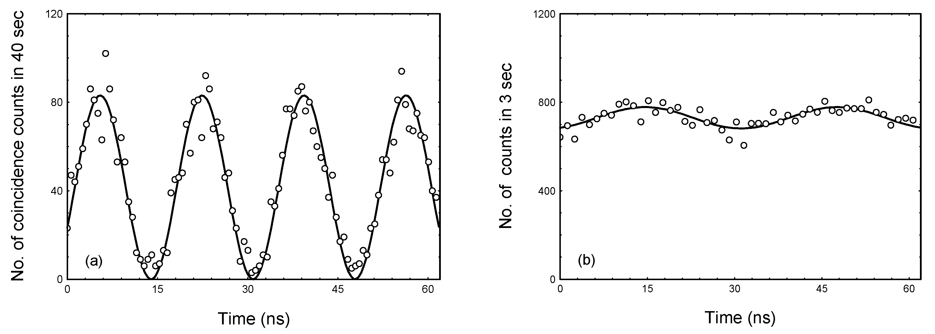
Figure 7a. The photon coincidence rate between the outputs of the optical beam splitter (BS) varies periodically over time, with a frequency twice that of the ultrasonic wave and nearly 100% modulation depth.
The obtained coincidence result, shown in
Figure 7a, is in agreement with Equation (16), which describes the two-photon beat phenomenon. In the maximum modulation of the number of coincidences, we have only 80 coincidences, which gives a measurement error of about 11%. Extending the measurement time does not yield any benefit because it increases the influence of θ and δ phase fluctuations, which in turn reduce the modulation depth. These fluctuations are caused by fluctuations in the temperature of the acousto-optical medium (water at a temperature of 21 degrees Celsius).
According to Formulas (15a) and (15b), the number of single photons at the output of the optical beam splitter (
BS) does not depend on time. In this case, the second-order interference disappeared. As shown in
Figure 7b, the slight modulation of the number of single photons is 6.6% with the frequency of the ultrasonic wave, due to the slight difference in the number of photons at the inputs of the 50:50 acousto-optical beam splitter (
AOBS) and the imperfect overlap of photons incident on the ultrasonic beam.

