1. Introduction
Raman assays for low-concentration biological solutions have garnered significant attention in the biomedical field. This is primarily due to the potential for rapid in vivo detection in humans, which allows for early diagnosis and monitoring. Currently, chromatography, electrochemistry, enzyme-linked immunosorbent assay (ELISA), and fluorescence analysis are the main methods used in Analytical Chemistry to detect specific substances in low-concentration biological solutions. Although many teams are currently conducting experiments to decrease solution concentrations to the detection limit, reference analysis still faces several challenges, including low sensitivity, the need for specialized analytical expertise, and time-consuming processes [
1,
2,
3,
4]. By contrast, surface-enhanced Raman scattering (SERS) is gaining popularity in microfluidic sensing applications due to its high sensitivity, precise selectivity, and rapid data acquisition. Numerous studies have investigated the application of surface-enhanced Raman spectroscopy for biomarker detection [
5,
6,
7]. However, most research on SERS detection faces substantial challenges in the development of plasmonic nanostructures [
8]. These challenges typically include time-consuming processes, complex fabrication, special chemical labeling, poor reproducibility, and the generation of random hotspots. Therefore, there is a clear need for simple and rapid nanostructure development in SERS [
9,
10]. SERS possesses the remarkable capability to achieve ultra-high sensitivity, even enabling the detection of single molecules in laboratory settings [
11]. However, its practical application still faces several challenges, such as the difficulty of effectively concentrating trace molecules within the enhancement region, particularly in complex liquids. Moreover, the technique demands significant processing time and a high level of expertise. Consequently, there is a pressing need to develop more convenient nanostructuring methods and faster detection processes. Depending on the SERS enhancement principle and the practical application environment, SERS sensitivity enhancement can be optimized according to the sample to be detected (detector enrichment, selective capture, etc.).
Therefore, we developed and optimized a ringless hydrophobic material for the Raman detection of low-concentration solutions in interdisciplinary biological research. We successfully enriched gold nanoparticles using an Interdigitated Transducer (IDT) enrichment microchip [
12,
13,
14,
15]. IDT stands for “Interdigitated Transducer,” an interdigital converter used in various applications, including the enrichment of gold nanoparticles. Structural analysis of the enriched gold particles at different power levels was conducted to facilitate SERS. Raman detection spectroscopy was performed on the enriched gold nanoparticles. Based on the designed enrichment microfluidic chip with Raman detection, we carried out a large number of theoretical analyses, simulations, and experimental analyses and proved that the SAW control has a significant effect on the aggregation of nanoparticles to form SERS hotspots. The surface acoustic waves (SAW) propagate inside the microdroplets resulting in kinetic and thermal impacts [
16]. This study highlights the potential of the developed surface acoustic wave (SAW) device. This technology could pave the way for innovative advancements in the development of microfluidic chips. These advancements are particularly relevant in interdisciplinary fields such as low-concentration drug detection, disease mechanism analysis, and life sciences.
2. Device Principle and Simulation Analysis
IDTs are deposited on a piezoelectric substrate, which generates surface acoustic waves (SAWs) on piezoelectric material due to the inverse piezoelectric effect when energized [
13]. The structural parameters of an IDT, such as the finger width, determine the frequency of the SAWs. The alternating strains within the piezoelectric material produce SAWs that propagate both longitudinally and transversely along the substrate’s surface. As these waves interact with a solid–liquid interface, energy attenuation occurs. This property makes Rayleigh waves ideal for transferring attenuation energy from solids to liquids, which makes Rayleigh waves commonly used in microfluidic applications [
17].
In order to determine the time-averaged acoustic radiation force on a spherical particle, which results in a net displacement of the particle other than localized oscillations, first-order acoustic pressure and velocity need to be obtained. According to the Navier–Stokes equations, the governing equations describing the conservation of momentum and the continuity of the fluid flow are as follows:
where
is the fluid density,
is the fluid velocity vector,
is the fluid pressure, and η is the shear viscosity. There is no regular flow of fluid until the SAW is operating. Therefore, the mass density and pressure of the fluid are measured. Equation (1) is sufficient for solving for the propagation of sound waves the through a medium and is suitable for conventional acoustics. However, for the acoustic radiation force, the acoustic field under first-order acoustic approximation has zero mean over a period of time, so the acoustic field has zero mean over a considerable time scale and does not produce an acoustic radiation force. Therefore, the derivation of the acoustic radiation force equation needs to take into account the second-order term of the acoustic field.
For acoustic vibrations with sinusoidal excitation, the acoustic pressure, velocity, and density perturbations in the medium average to zero over one vibration cycle. Consequently, the acoustic radiation force on the particles in the medium also averages to zero over time. This is due to the fact that we neglect the vibrational terms above the second order when deriving the acoustic wave equation.
where
c0 is equal to the value of the velocity of sound in the fluid as a constant, first-order sound pressure is
, and velocity is
. The second-order term is negligible relative to the first-order term. However, it is assumed that the time-averaged results of the higher order terms are not zero. In this case, the second-order terms need to be considered. Calculating their time averaging over a period of time indicates the time-averaged effect of the acoustic wave on the particles. The average over a period of time can be derived as follows:
where the time function ⟨
X ⟩ can be defined by the average value of the physical quantity
X. We numerically simulate the acoustic pressure and flow velocity flow shape of the microfluidic chip droplet flow field by using COMSOL 6.1 software and also analyze the mechanism of the action of acoustic surface wave propagation radiation coupled with the fluid. After neglecting higher order terms, the boundary conditions at these interfaces are as follows:
where Z
0 is the acoustic impedance of the droplet boundary, and
l is Channel cross section width. The water–lithium niobate interface is characterized by impedance or lossy wall boundary conditions, where the energy of the acoustic wave is partially absorbed by the solid wall.
3. Experimental Materials and Devices
To ensure precise control over the experiment, we first set up the system by enriching the lower layer where the RF amplifier (Pulin Electronics, Hefei, China) was placed. To protect the system from potential overload caused by instantaneous high signals, a 20 dB attenuator (AD8318, R&D Electronics, Guilin, China) was installed at the front end of the RF amplifier. The RF signal source (RIGOL DG4102, Suzhou, China) signal was attenuated and then fed into the RF amplifier. The output from the RF amplifier was then connected to an RF coupler (ZFBDC20-62HP-S+, Mini circuits, New York, NY, USA). The two detection ports of the RF coupler were connected to a power meter (AD8318, R&D Electronics, Guilin, China) to separately detect the input and reflected power. Additionally, four power meters were placed on the upper level of the system to monitor the inputs and outputs.
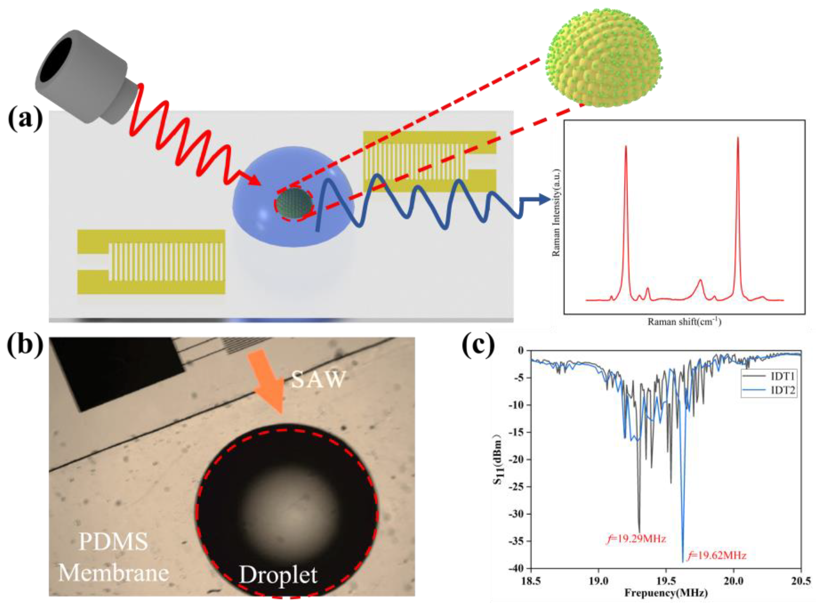
In
Figure 1, the experimental setup and key results for surface acoustic wave (SAW)-based enrichment and Raman sensing of gold nanoparticles (AuNPs) are presented.
Figure 1a shows a schematic diagram of the setup, where SAWs are utilized to manipulate a droplet containing AuNPs, thereby enhancing the Raman signal for subsequent detection.
Figure 1b provides an optical image of the PDMS membrane with a sessile droplet, demonstrating the role of SAWs in concentrating nanoparticles within the enhancement region. The arrow indicates the direction of SAW propagation, and the red circular wave represents the droplet. The polydimethylsiloxane (PDMS) membrane is a silicone-based organic polymer known for its flexibility and biocompatibility.
Figure 1c illustrates the reflection coefficient (S
11) as a function of frequency for dual IDT, with emphasis on the critical operating frequencies (19.29 MHz and 19.62 MHz) that achieve optimal SAW coupling, which is crucial for effective nanoparticle aggregation and improved Raman sensing performance.
Lithium niobate (LiNbO3) was selected as the piezoelectric substrate for generating highly efficient surface acoustic waves (SAWs) due to its low energy loss at MHz frequencies, which is ideal for electromechanical interaction wavelengths. We used 128° YX-cut 4-inch LiNbO3 (500 μm thick, SAW-grade, polished on both sides) as the substrate. The fabrication of the SAW chips involved using chemicals such as anhydrous ethanol (C2H6O, 99.9%, Sigma-Aldrich, Burlington, MA, USA), trichloro(1H, 1H, 2H, 2H-perfluorooctyl)silane (PFTS, C8H4Cl3F13Si, ≥97%, Sigma-Aldrich), and PDMS material. The LiNbO3 chip was thoroughly cleaned in a plasma cleaner at 100 W for 10 min. Following this, the chip underwent hydrophobization to facilitate the bonding of the PDMS membrane to the chip and to minimize the loss of acoustic wave pairs.
The reagents used in the experiments included 50 nm gold nanoparticles (AuNPs) at a concentration of 1.67 × 10¹¹ particles/mL in a stabilized suspension with citrate buffer, deionized water (H2O) produced domestically, magnesium chloride (MgCl2) for solution preparation, and methanol (CH3OH) for cleaning processes. The gold precursor solution was prepared by first dissolving polyvinylpyrrolidone (PVP) in deionized water, followed by dissolving high-purity chloroauric acid (HAuCl4) in deionized water. The PVP solution was then rapidly added to the chloroauric acid solution under heating and stirring conditions. The reducing effect of PVP generated gold nanoparticles, which were subsequently adsorbed onto the particle surfaces through physical adsorption, forming a protective layer. The resulting 50 nm gold nanoparticles were obtained through filtration and washing.
To confirm the operating frequency of the dual IDT, its reflection coefficient S11 was measured using a vector network analyzer, allowing us to optimize the coupling power and prevent device damage due to excessive power reflection. The measured difference between input and reflected power was about 20 dBm, aligning with the experimental parameters. Device testing showed that it took over 7 min for surface acoustic waves to induce micron particle enrichment. Evaporation’s impact on the enrichment process was minimal, with less than a 5% reduction in droplet volume over 7 min. However, after 12 min, the droplet volume decreased by over 30%, along with a decrease in contact angle and contour contraction.
The concentration of 4-MBA used in the experiments ranged from 10−4 to 10−8 mol/L. To functionalize the AuNPs, 3 μL of 4-MBA solution at varying concentrations was added to the enriched and dried gold nanoparticles. The samples were left to dry completely before being used for Raman detection. The SERS measurements were conducted with a wavelength of 785 nm, 50 mW laser power, and acquisition time of 2 s.
4. Results and Discussion
4.1. Simulation Analysis of Acoustic Surface Waves and SERS of Gold Nanoparticles
In this section, we focus on the influence of the driving frequency of the acoustic surface wave and the vertical height of the droplet on the effect of the acoustic field action. According to the resonant modal analysis of the SAW device in the previous section, we know that Rayleigh waves can be generated only in a specific frequency range, so we select three input frequencies near the intrinsic frequency of the SAW device, which has a finger spacing of 50 μm based on the previous calculations, with a range of 15 MHz to 25 MHz. The SAW sound field generated by the dual IDT with 50 μm finger spacing is simulated using COMSOL; at the same time, the physical field of the circuit is input with a certain value of voltage. An AC source with a frequency, f0, is applied, and a parameter scan for f0 is conducted using the frequency domain calculation interface. For this scan, three frequencies were selected: 15 MHz, 19.581 MHz, and 25 MHz. Among these, the frequency of 19.581 MHz proved to be the most effective for achieving optimal results in the acoustic field.
Thus, by re-substituting these specific frequencies into the steady-state calculation at 19.581 MHz and focusing on the 200 μm droplet height, we were able to achieve superior control over the acoustic pressure and sound velocity fields, leading to enhanced device performance and more effective droplet manipulation. The final simulation results for the acoustic-fluid-coupled field are presented in
Figure 2.
The above results indicate that for the acoustic field, the wavelength of the acoustic field as it propagates in the vertical direction starts to become smaller as the frequency increases and starts to form more pressure nodes in the vertical direction gradually. On the other hand, for the flow field, from the white streamline trajectory, it can be found that the closer to the resonant frequency set by the IDT, the more ordered the vortex field generated. A thorough analysis of the acoustic and flow field simulation maps reveals that the most efficient vortex flow occurs near the IDT’s resonance frequency. This optimal vortex flow is crucial for effectively concentrating particles within the droplet, as it enhances the enrichment process by directing particles towards the center of the droplet with greater precision and consistency.
We focus on the effect of droplet height on the vortex motion, mainly discussing the effect of droplet height on the acoustic flow in the vertical direction; a certain droplet height is required to generate vortex acoustic flow in the droplet [
18,
19]. The droplet height parameter is parametrically scanned, and three heights are set up for comparison—180 μm, 200 μm, and 220 μm—corresponding to the low, medium, and high droplet heights, respectively. The white streamlines in the second-order flow field (the white arrows represent the direction of the streamlines) show that, at a droplet height of 200 μm, the particles inside the sessile droplet follow the vortex field and rotate towards the center. On the contrary, a droplet height of 180 μm does not allow for the formation of vortex lines inside the droplet, as shown in
Figure 2b. Therefore, the enrichment effect at a height of 200 μm meets the experimental requirements. On the basis of the above, the bias of droplets is analyzed with single and dual IDT for sound pressure simulation.
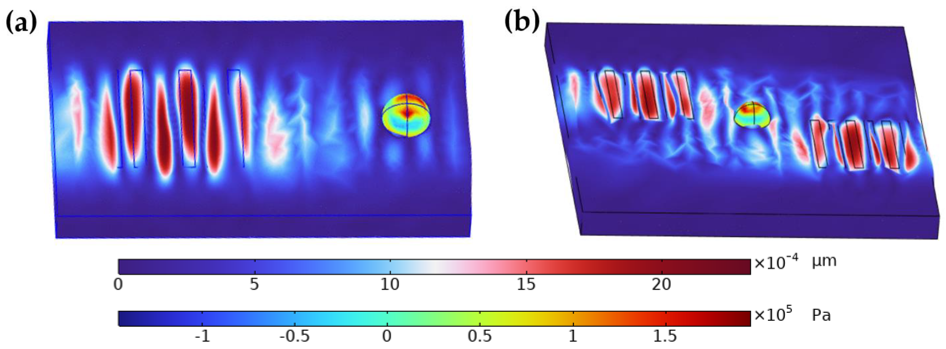
In the study, both single and dual IDT were employed to evaluate their effectiveness in droplet enrichment. The results are visually represented in
Figure 3, which compares the sound pressure fields generated by single IDT (
Figure 3a) and dual IDT (
Figure 3b) configurations. The images illustrate that the dual IDT setup produces a more uniform and concentrated acoustic field around the droplet, enhancing the nanoparticle enrichment process.
Specifically,
Figure 3b shows that the dual IDT configuration creates multiple high-intensity regions that better trap and concentrate nanoparticles within the droplet, compared to the single IDT configuration shown in
Figure 3a. This leads to more efficient and consistent enrichment, which is critical for improving the sensitivity and uniformity of SERS detection. Therefore, the conclusion that “the dual IDT is more effective for droplet enrichment” is well supported by the simulation data presented in these figures and aligns with the observed experimental outcomes.
Raman scattering is a phenomenon of inelastic scattering of photons, where the frequency of the scattered light differs from the frequency of the incident light. The modeling of this nonlinear Raman scattering process is extremely challenging, similar to other nonlinear optical processes. In most studies, finite-difference time-domain (FDTD) methods are used to measure the scattering enhancement effect.
To simplify the computational process, this is usually achieved by linear simulation, which makes the simulation setup and the analysis of the results more convenient. The enhancement factor (EF) is usually defined ((E/E
0)
4), where E is the local maximum electric field strength, and E
0 is the electric field amplitude of the input source in a linear simulation. The measurement of local enhancement factors is conducted in the vicinity of smooth gold nanoparticles [
20]. This study demonstrates the use of surface acoustic waves (SAWs) to enhance surface-enhanced Raman spectroscopy (SERS) detection by optimizing nanoparticle enrichment within droplets, using FDTD simulations with a 50 nm sphere positioned at (x = −55 nm, y = 0 nm, z = 41 nm), a mesh accuracy of 2, a minimum mesh step of 0.4 nm, and boundary conditions configured with 32-layer Perfectly Matched Layers (PMLs) to minimize reflections. The interaction between the particles and the surface will result in a strong local enhancement of the field, as shown in
Figure 4.
4.2. Morphological Characterization of Micro Droplets
To verify the operating frequency of the dual IDT, its reflection coefficient (S
11) was measured using a vector network analyzer (Libre VNA, Shanghai, China). A vector network analyzer is an instrument used to measure and analyze high-frequency circuits and devices, and it measures the S-parameter (scattering parameter) of a circuit or device, which includes amplitude and phase information, as well as attenuation, reflection loss, and phase delay. By monitoring the changes in S
11 in real time, it is possible to maximize the coupling power of the dual IDT to emulate power reflection leading to device damage [
21]. The measured difference between input power and reflected power for the acoustic tweezer device is approximately 20 dBm, meeting the necessary experimental parameters. Otherwise, the reflected power is too large, the surface device does not efficiently couple the signal power, in which case the risk of device damage increases if too much time passes.
We tested the device to determine the time required to induce micron particle enrichment using surface acoustic waves. The findings revealed that the process takes over 7 min. However, during the manipulation of sessile droplets, evaporation could potentially impact the effectiveness of enrichment [
22]. Therefore, experiments were carried out to analyze the change in droplet state with time under specific temperature and humidity conditions.
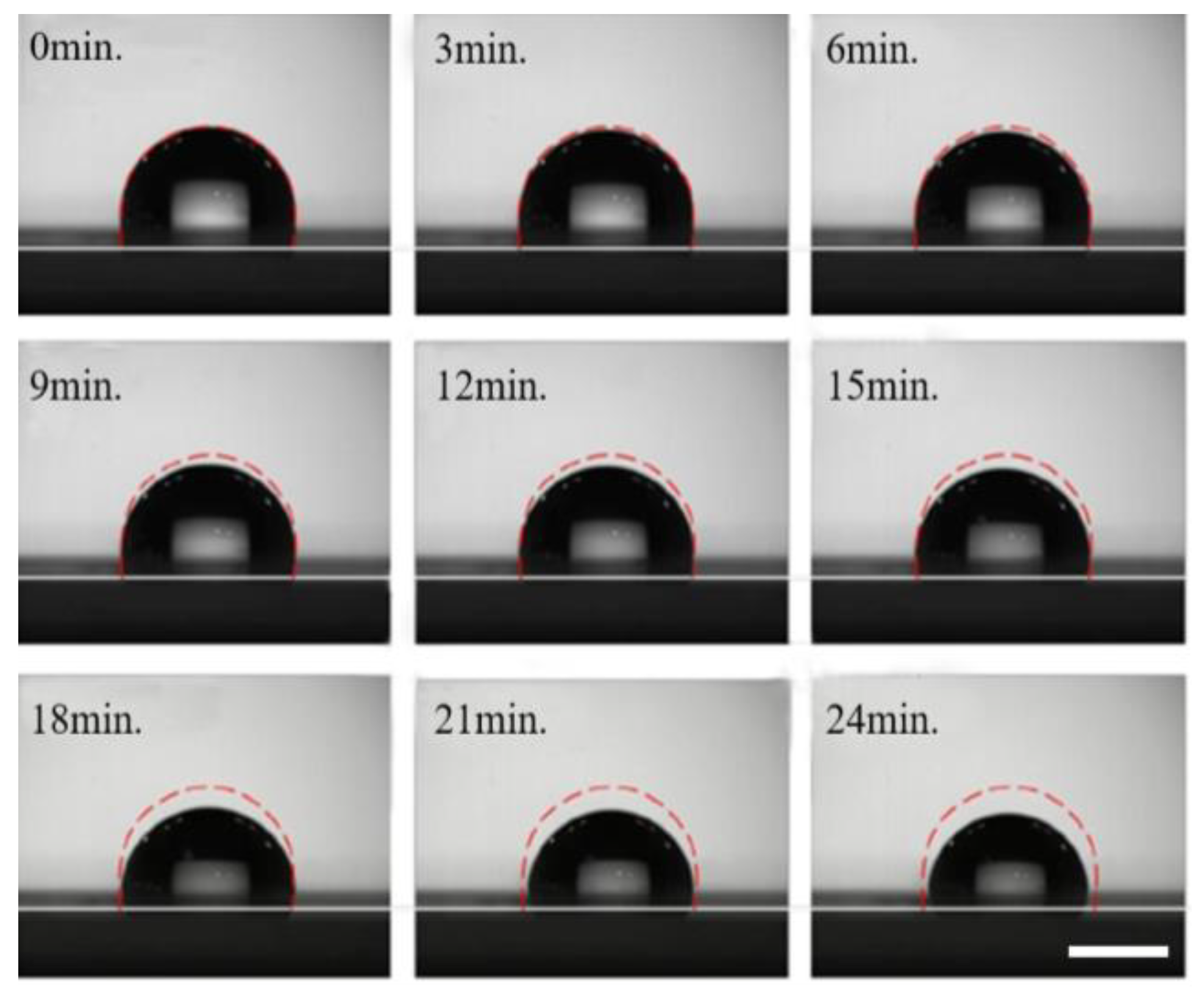
The specific operation process is as follows: we placed the prepared chip in the observation area of the contact angle measuring instrument. A pipette was used to deposit a 5 μL sample of gold nanoparticle solution onto the surface of the PDMS film. The changes in the contour of the droplets at different moments were recorded using a high-speed CCD camera. As shown in
Figure 5, the droplet volume decreased by less than 5% over 7 min. The changes in the droplet’s volume and shape were almost negligible, indicating minimal environmental influence during the enrichment process. At 12 min, the droplet profile changes significantly, with a significant reduction in volume from the initial state. The droplet volume continues to decrease over time, and by 22 min, it has decreased by more than 30%. Additionally, the contact angle decreases, and the contour line contracts inward. These results suggest that droplet evaporation significantly impacts the enrichment process when the duration exceeds 10 min. Therefore, without controlling ambient temperature and humidity, droplet manipulation using the acoustic tweezer chip should not be performed for more than 10 min.
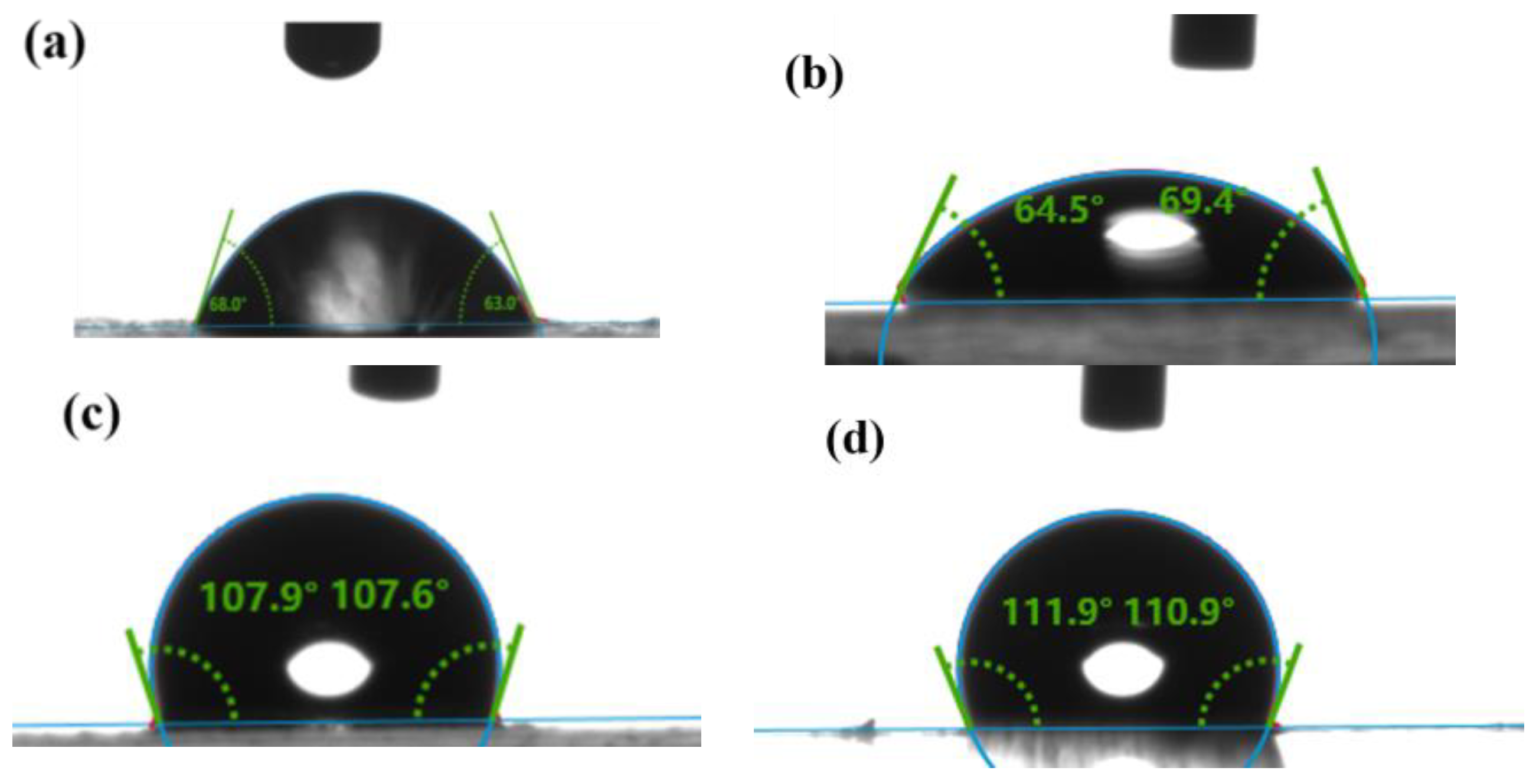
We analyzed the enrichment experiments; the acoustic wave was excited by the IDT and then propagated along the substrate and coupled into the droplet through the PDMS film. Given the substantial impact of droplet height on enrichment, a clear correlation between the contact angle and droplet height was observed. Consequently, our investigation focused on examining the hydrophobic angles presented by various materials. The contact angle measurements of the droplets on the PDMS film, the glass surface, the lithium niobate surface, and the hydrophobic layer of the PFTS reagent are shown in
Figure 6. The results show that the contact angle of the PDMS film is approximately 110°, which is smaller than the rolling contact angle of the droplet and therefore prevents the droplet from rolling. Compared with the droplets placed directly on the glass substrate surface, higher volume droplets can be driven on the PDMS film with the same contact area, while the larger contact angle helps the droplets maintain a stable state and profile.
The research describes how, during the drying process, gold nanoparticles become enriched and aggregate at the center of the droplet, forming a concentrated platform onto which the 4-MBA molecules adsorb. There is no interaction or aggregation between the 4-MBA molecules themselves. The enhanced Raman signal arises from the reduced distance between the 4-MBA molecules and the aggregated nanoparticles, rather than from any aggregation of the 4-MBA molecules.
The macroscopic observation of the SAW-driven droplet enrichment drying process is shown in
Figure 6. On the PDMS film, the contact angle of the droplets is approximately 100°, and significant deformation of the droplets occurs under the influence of surface acoustic waves compared to their stationary state. It has been demonstrated that when the acoustic frequency is between 19 MHz and 20 MHz, the droplets can be efficiently enriched and dried within just 7 min. When observed through a high-speed microscopic camera, the PDMS film reveals the captivating phenomenon of droplets undergoing rapid rotational motion, driven by the acoustic waves [
23]. Acoustic waves penetrate the substrate along the propagation path and couple with the fluid to drive the particles in the droplets. Under the microscope, it is obvious that a gray spot is formed in the center region of the droplet. This indicates that 50 nm of gold particles were successfully aggregated in the center region of the droplet [
24]. The in-depth analysis of the enrichment effect was performed using scanning electron microscopy (SEM). The SEM images taken from enriched regions showed the morphologies of the nanoclusters. Under the effect of hydrophobicity and SAW, the nanoclusters are more distinctly characterized in the profile image, which significantly increases the intensity of the surface-enriched Raman signal. This enhanced signal performance allows the detection of low concentration targets to reach the boundaries of high sensitivity.
The examination of the simulation data reveals a positive correlation between the amplitude of acoustic waves and the intensity of acoustic flow. During the experiment, it was observed that increasing the input power led to a greater amplitude of surface acoustic waves, which in turn amplified the intensity of the acoustic flow. This enhanced acoustic flow significantly improved the efficiency of particle enrichment within droplets [
25]. Based on this, the previous chapter describes the use of experiments to study 50 nm gold nanoparticles in droplets under different input powers. The best enrichment effect was obtained at 200 mW. Based on the experimental results, as shown in
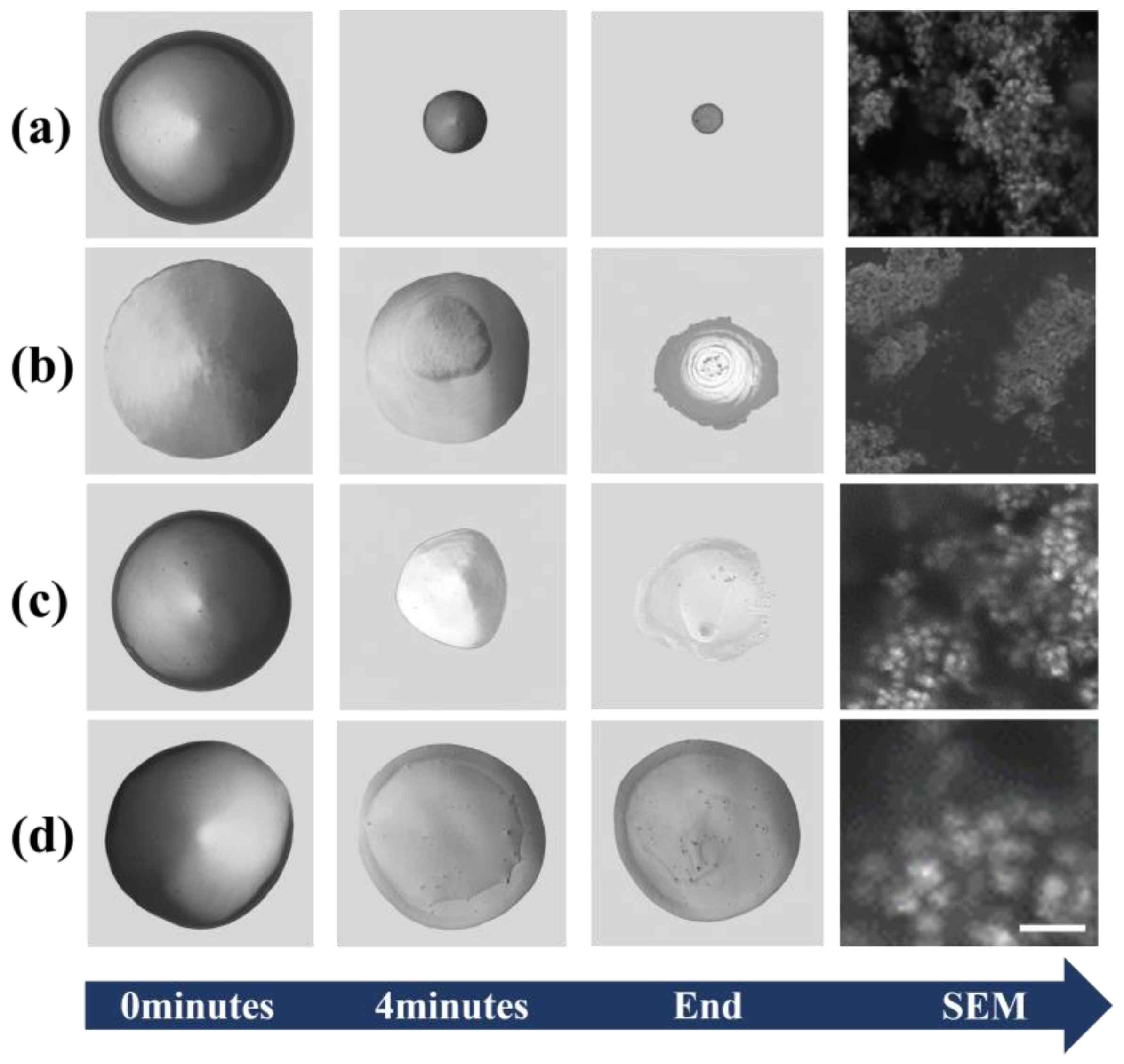
Supplementary Figure S4, the center of the chip observed under the particle enrichment microscope revealed that 5 μL droplets, quantitatively measured with a pipette, were placed on the propagation path of the surface acoustic wave. The droplet was rotated through by a high-speed camera and microscope shot. The evaporation process of the droplets containing 4-MBA and AuNPs on the SAW chip was studied under varying input powers to determine the optimal conditions for nanoparticle enrichment. The Raman spectra were recorded using 4-MBA (4-mercaptobenzoic acid) as the analyte. The presence of SAW and hydrophobic coating created a favorable environment for the particles to aggregate into a single point during the evaporation of the droplets. The results are shown in
Figure 7.
We carefully observed the enrichment process of 50 nm particles over time, when the input power of the external signal was set in the range of 11 to 12 V. The results show the significant enrichment of 50 nm within the droplet at 120 s. Through a comparative analysis of four different models, we verified the effect of the SAW with hydrophobic layer treatment. In the experiments, 5 μL of a colloidal solution of gold nanoparticles (AuNPs), was added dropwise onto a lithium niobate chip [
26].
Figure 7 above depicts the time sequence of colloidal solution evaporation under different surface conditions. In
Figure 7a, the AuNPs show a point-like distribution that overcomes the deposition of coffee rings due to acoustic flow with hydrophobic corners. In
Figure 7b, the AuNPs display a faceted arrangement over a relatively large area due to their hydrophilic nature. In
Figure 7c,d, due to the unopened SAW, there was a rather noticeable coffee ring phenomenon. We were able to clearly observe that different surface properties and the presence or absence of acoustic waves had a direct and positive effect on the aggregation behavior of AuNPs.
4.3. Validation of the Detection Capability for Analyzing SERS Substrates
We optimized our SAW-activated SERS platform by applying hydrophobic treatment and regulating the working power. To investigate the SERS detection rate of our optimized platform, 4-MBA was used as a pre-tested probe analyte. The spectral analysis of 4-MBA was conducted using gold nanoparticle clusters under uniform experimental conditions at concentrations ranging from 10
−4 to 10
−7 mol/L. Each spectral pattern was obtained using these gold nanoparticle clusters [
27,
28].
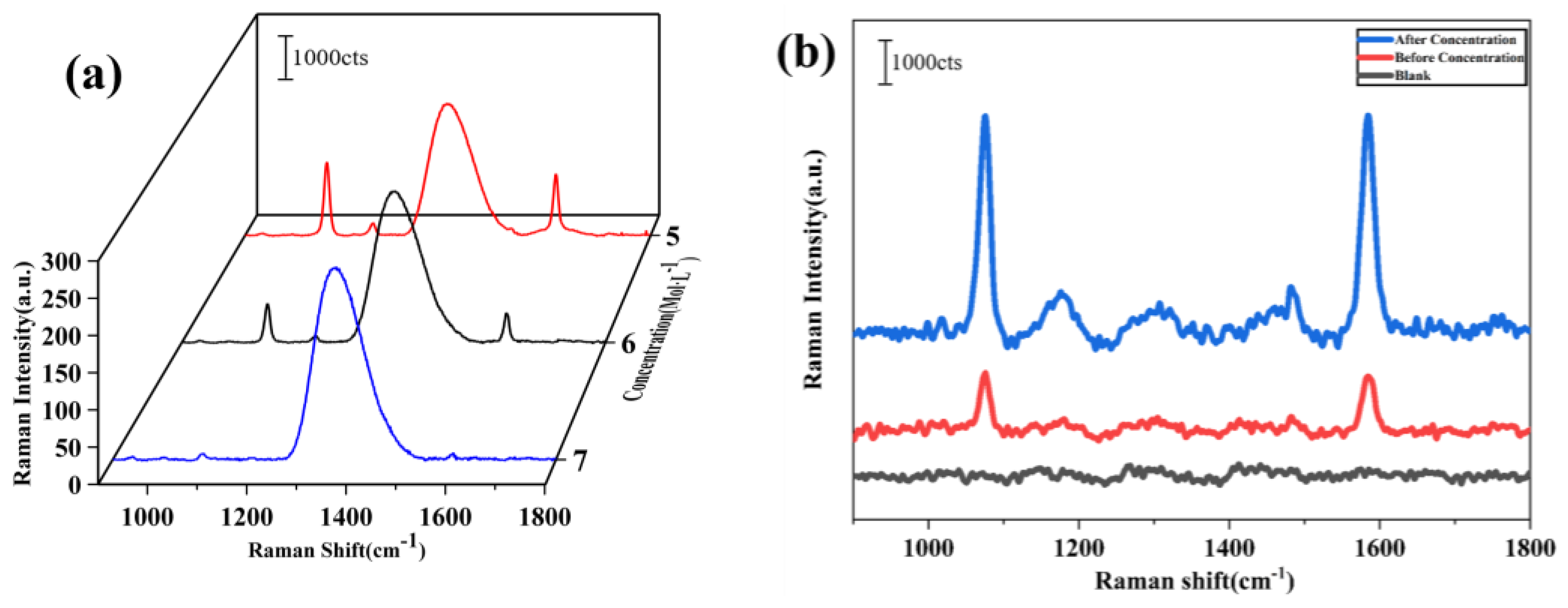
Differences in the characteristic peaks were observed at wave numbers 1074, 1180, 1410, and 1583 cm
−1 as the concentration of 4-MBA varied. In particular, the intensity of the peak at 1583 cm
−1 diminished as the concentration decreased to the 10
−8 mol/L. In addition, the detected intensities of the Raman peaks before and after enrichment, as well as without enrichment, were compared, and the discrepancies are visualized in
Figure 8b. These results indicate that the detection sensitivity of Raman signals can be significantly enhanced by the enrichment process, particularly when using surface acoustic waves (SAWs). The enhanced sensitivity is attributed to the more uniform and controlled aggregation of nanoparticles facilitated by the SAWs, which contrasts with the less consistent results often seen with drying methods. Unlike the drying process, which can lead to uneven nanoparticle distribution and reduced hotspot formation, the acoustic wave concentration method ensures a more homogeneous distribution of nanoparticles. These results indicate that the detection sensitivity of Raman signals can be significantly enhanced by the enrichment process. The detailed results of the optimized enrichment effect and its facilitation of Raman detection are demonstrated in
Figure 8.
With Raman spectra obtained from data processing, the broad peak observed in the 1350–1400 cm−1 range can be attributed to fluorescence. Fluorescence typically manifests as a broad, less-defined peak, resulting from the re-emission of absorbed light by the sample. In this case, the 4-MBA molecules, or their interactions with the substrate, are responsible for this fluorescence, which overlaps with and broadens the Raman signal. This phenomenon is common in Raman spectroscopy, particularly when specific excitation wavelengths cause the sample or its environment to emit light that obscures or broadens the characteristic Raman peaks.
The aggregation of AuNPs into closely packed nanoclusters under enrichment conditions significantly amplified the Raman scattering signals, a phenomenon particularly evident at very low concentrations of 10−8 mol/L. Even at such trace concentrations, the clarity and detectability of the Raman peaks were not impaired, demonstrating excellent analytical performance. To confirm the amplification effect, a comparison with spectra obtained without the enrichment factor was performed.
In our study, the surface-enhanced Raman scattering spectra of 4-MBA were analyzed in depth. The changing law of Raman peak intensity under different concentration gradients was explored in detail [
29]. The experimental results showed that as the concentration of 4-MBA decreased, the intensity gradually declined, down to 10
−8 mol/L. This phenomenon reveals the nature of the linear regression between the logarithm of molecular concentration and the SERS intensity. The results are shown in
Figure 9.
In summary, compared to the non-concentrated state, the concentrated sample exhibited a 100-fold enhancement in Raman peak intensity, with the detection concentration reaching 10−8 mol/L. The 100-fold improvement in the detection limit is based on the comparison between the Raman spectra of the concentrated and non-concentrated samples. While the total concentration of AuNPs and 4-MBA in the droplet remains unchanged, the concentration process effectively increases the local electromagnetic field, thereby enhancing the Raman signal. The significant difference in signal intensity between these two states directly supports the claim of a 100-fold improvement in detection limit. This significant improvement in Raman signal was attributed to the localized electromagnetic field enhancement induced by the metal nanoclusters, which greatly increased the sensitivity of the SERS detection. Although the overall concentration of AuNPs and 4-MBA in the droplet remained unchanged, the concentration process led to a substantial increase in the local electromagnetic field, thereby amplifying the Raman signal intensity. This strategy not only bolsters the effectiveness of SERS technology in detecting low-concentration molecules but also paves the way for innovative applications in biomolecule detection, environmental monitoring, and materials science. This work underscores the essential role of Raman spectroscopy in advancing analytical chemistry and bio-detection technologies.
