1. Introduction
Multi-pass laser amplification systems constructed with large-aperture Nd:glass are the main part in high-power laser facilities [
1] such as the National Ingition Facility (NIF) [
2], OMEGA [
3], and XG-III [
4]. The reflection of laser light occurs when, for example, stimulated Brillouin scattering (SBS) and stimulated Raman scattering (SRS) occur in the propagation of a laser beam, or when laser radiation is focused on a solid target in the target chamber.
As the fluorescent lifetime of Nd:glass is more than 300 μs, the retro-reflected pulses may be amplified when they travel back through the Nd:glass. If these pulses are not suppressed, they may cause damage to the optical components.
In order to reject pulses that may be retro-reflected from the target chamber, large-aperture polarizers in conjunction with a plasma-electrode Pockels cell (PEPC) are used in most high-power facilities [
5]. High-quality, large-aperture polarizer coatings are greatly challenging due to the beam aperture, desired incident fluence, and the need for the spectral bandwidth of the incident pulses [
6].
Here we propose an approach of optical isolation without large-aperture polarizers. Instead, an ordinary, small-aperture polarizer and a small-aperture plasma-electrode Pockels cell are added. Theory analyses based on Jones matrix and applications in the XG-III PW beamline were carried out to validate this approach.
2. Scheme of Optical Isolation
The XG-III laser facility [
7] is constructed for intense laser-matter interaction research. One beamline of this facility delivers 300~500 J, 650 fs~10 ps, width-adjustable, pettawatt-class laser pulse to the target. In this short-pulse system, the OPA seed is amplified by two-stage OPCPAs, boosted to hundreds of joules by the main beamline amplifier, and then compressed back to a short pulse.
The main beamline amplifier is shown in
Figure 1. A
p-polarized pulse from the front end is directed into the main beamline amplifier through an injection mirror IM0 near the pinhole array PA2. It expands to a beam size of 150 mm × 150 mm and passes through a 6-disk amplifier and 8-disk amplifier successively in the first amplification pass, reflects off of a cavity mirror CM, and then goes through the two amplifiers again for the second amplification pass. The amplified pulse reflects from the pick-off mirror BM1, and enters the beam reverser with a beam-size contraction to 60 mm × 60 mm. The beam reverser serves as a switch: it can control the transmission of laser beams.
In the beam reverser, the main pulse goes through a reversal lens group composed of BM3, BM4, and BM5, with the beam polarization rotated by 90°. Then, a small aperture PEPC working at a half-wave voltage rotates the beam polarization back to p-polarization. The residual, s-polarized beams are removed by a polarizer. Finally, the main pulse returns to the 6-disk amplifier and the 8-disk amplifier by BM7 for the third and fourth amplification passes. After the fourth-pass amplification, the main pulse goes through a large-aperture PEPC which has been fired to rotate the beam polarization by 90°, delivering an s-polarized pulse to a compressor.
When the laser pulse reflection from the target chamber occurs, the retro-reflected pulse travels back through the optical path and is enhanced by amplifiers. The optical isolation is designed as shown in
Figure 2. The large-aperture PEPC is switched off when the retro-reflected pulse travels back, delivering an
s-polarized pulse to the amplifiers. The Nd:glass slabs in the amplifiers, placed at the Brewster′s angle, and the polarizer in the beam reverser can remove some of the
s-polarized pulse. The retro-reflected pulse travels through the small-aperture PEPC, which is switched off, and then through the reversal lens group, transforming the pulse to p-polarization. Finally, the retro-reflected pulse is delivered into the front end after two passes of amplification.
3. Theoretical Analyses of the Optical Isolation
The pick-off mirrorBM7 and the front end may take over higher-energy laser pulses than other components due to the beam-size contraction. It is essential to analyze the energy densities on the two components.
The retro-reflected pulse travels forward and backward through the compressor, which consists of two of the same optical gratings [
8,
9]. The diffraction efficiencies for the
p- and
s-polarized beams of the optical grating are 25% and 92%, respectively. Therefore, the Jones matrix of the compressor is:
The two PEPCs have been switched off when the retro-reflected pulse travels back. The transmittance and the static contrast ratio of the PEPC are 93% and 400:1, respectively. Therefore, the Jones matrix of the PEPC is:
There are 14 (6 + 8) pieces of Nd:glass slabs in single-pass amplification. Each glass operates at the Brewster′s angle. The power magnifications for the
p- and
s-polarized pulses of a single Nd:glass are 1.14 and 0.83, respectively. The Jones matrix for a single-pass amplification with 14 pieces of Nd:glass slabs is:
The
p- and
s-polarized transmittances of the polarizer are 98% and 0.5%, respectively. Therefore, the Jones matrix of the polarizer is:
The reversal lens group can transform 99.6% of the p-polarization to s-polarization and vice versa. Therefore, the Jones matrix of the reversal lens group is:
From
Figure 2, we can see that the retro-reflected pulse on the BM7 traveled through the compressor, the large-aperture PEPC, and the amplifier for two passes. Therefore, the transmission matrix for the retro-reflected pulse from the compressor to the BM7 is:
The retro-reflected pulse on the front end traveled through the compressor, the large-aperture PEPC, the amplifier for two passes, the polarizer, the small-aperture PEPC, the reversal lens group, and the amplifier for two passes. Therefore, the transmission matrix for the retro-reflected pulse from the compressor to the front end is:
The energies of the retro-reflected pulse on the BM7 and on the front end are:
where
EP0 and
ES0 are the initial retroreflected energies for
p- and
s-polarized laser pulses, respectively; and
α1 = 0.85 and
α2 = 0.77 are the transmission rates of all the optical elements, from the compressor to the BM7 and to the front end. The optical isolation rates for
p- and
s-polarized pulses on the BM7 are 0.121 and 0.059, respectively. The optical isolation rates for
p- and
s-polarized pulses on the front end are 0.026 and 0.012, respectively.
After the compressor, the output energy of the main pulse can reach 300 J in the XG-III PW beamline [
10]. Assuming that the retro-reflectivity is
γ and the depolarization ratio is
β, the initial retroreflected energies for
p- and
s-polarized laser pulses are:
Substituting Equation (10) in Equations (8) and (9) with the values of
γ and
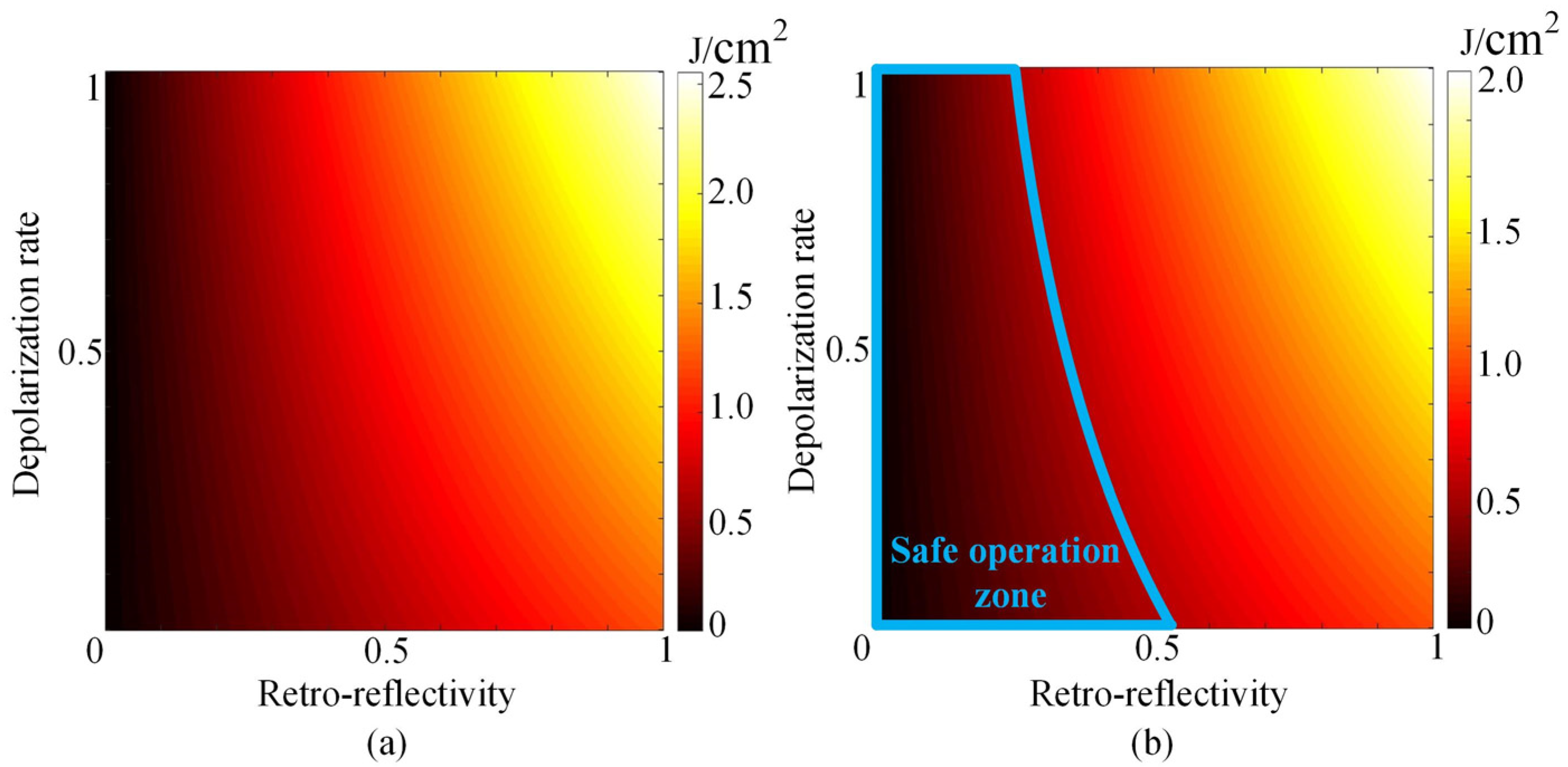
β ranging from 0 to 1, the beam sizes on the BM7 and on the front end are 3.2 cm × 4.5 cm and 2 cm × 2 cm, respectively. The energy densities of the retro-reflected pulse on the BM7 and on the front end are shown in
Figure 3.
It is noted that, from
Figure 3a, the maximum energy density on the BM7 is 2.6 J/cm
2, which is lower than its damage threshold of 26 J/cm
2. That is to say, the BM7 is still safe when the worst circumstances, with 100% reflection and 100% depolarization, occur.
For safe operation, the energy density on the front end is lower than 0.5 J/cm
2, which is the threshold of a Faraday isolator at the end of the front end. The safe operation zone is shown inside the blue lines in
Figure 3b. The figure shows that the operation is safe when the retro-reflectivity is lower than 25%, regardless of the value of the depolarization rate. If the retro-reflectivity is lower than 53%, the operation is safe as well. The conditions beyond the blue lines in
Figure 3b exceed the design of XG-III and rarely occur, so it is almost totally safe for the front end in operation.
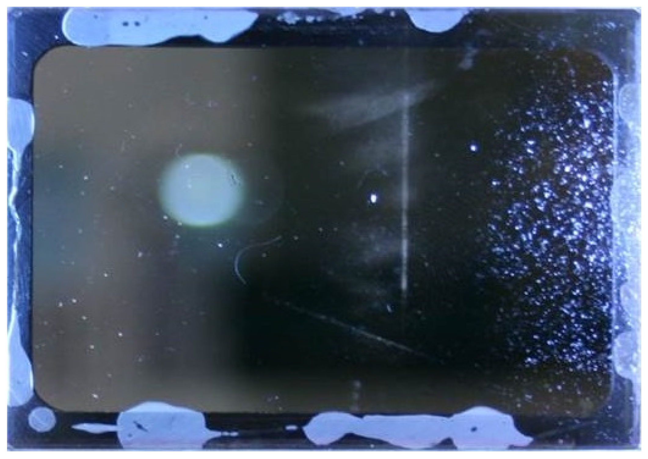
Figure 4 is a damaged pick-off mirror BM7 before the optical isolation is applied to the XG-III PW beamline. There are many damaged points on the mirror, in which case it usually needs to be replaced. Since we applied this optical isolation to the XG-III PW beamline, the damage has not happened.
4. Conclusions
In summary, we have proposed an approach of optical isolation without large-aperture polarizers in an XG-III beamline. The Nd:glass slabs in the main beamline amplifier are placed at the Brewster′s angle to remove some of the s-polarized pulse. A large aperture PEPC after the main beamline amplifier and a small-aperture PEPC in the beam reverser are designed to not only rotate the polarization of the main pulse by 90° when it is switched on but also to reject retro-reflected pulses (in conjunction with the Nd:glass slabs placed at the Brewster′s angle) when it is switched off.
The optical isolation rates for the p- and s-polarized pulses on the pick-off mirror can be achieved at 0.121 and 0.059, respectively. As is the case on the front end, the optical isolation rates for the p- and s-polarized pulses are 0.026 and 0.012, respectively. The theorical analysis shows that the optical isolation can well protect the laser system, and it indeed does so in the XG-III PW beamline.


