Article

Design and Efficiency Analysis of High Maneuvering Underwater Gliders for Kuroshio Observation

1
Tianjin Key Laboratory for Advanced Mechatronic System Design and Intelligent Control, School of Mechanical Engineering, Tianjin University of Technology, Tianjin 300384, China
2
National Demonstration Center for Experimental Mechanical and Electrical Engineering Education, Tianjin University of Technology, Tianjin 300384, China
3
Tianjin Fire Research Institute of Emergency Management Department, Tianjin 300381, China
4
Tianjin Hanhailanfan Marine Technology Co., Ltd., Tianjin 300457, China
*
Author to whom correspondence should be addressed.
Oceans 2025, 6(3), 48; https://doi.org/10.3390/oceans6030048 (registering DOI)
Submission received: 19 April 2025 / Revised: 19 July 2025 / Accepted: 25 July 2025 / Published: 1 August 2025

Abstract

The Kuroshio Current’s flow velocity imposes exacting requirements on underwater vehicle propulsive systems. Ecological preservation necessitates low-noise propeller designs to mitigate operational disturbances. As technological evolution advances toward greater intelligence and system integration, intelligent unmanned systems are positioning themselves as a critical frontier in marine innovation. In recent years, the global research community has increased its efforts towards the development of high-maneuverability underwater vehicles. However, propeller design optimization ignores the key balance between acoustic performance and hydrodynamic efficiency, as well as the appropriate speed threshold for blade rotation. In order to solve this problem, the propeller design of the NACA 65A010 airfoil is optimized by using OpenProp v3.3.4 and XFlow 2022 software, aiming at innovating the propulsion system of shallow water agile submersibles. The study presents an integrated design framework combining lattice Boltzmann method (LBM) simulations synergized with fully Lagrangian-LES modeling, implementing rotational speed thresholds to detect cavitation inception, followed by advanced acoustic propagation analysis. Through rigorous comparative assessment of hydrodynamic metrics, we establish an optimization protocol for propeller selection tailored to littoral zone operational demands. Studies have shown that increasing the number of propeller blades can reduce the single-blade load and delay cavitation, but too many blades will aggravate the complexity of the flow field, resulting in reduced efficiency and noise rebound. It is concluded that the propeller with five blades, a diameter of 234 mm, and a speed of 500 RPM exhibits the best performance. Under these conditions, the water efficiency is 69.01%, and the noise is the lowest, which basically realizes the balance between hydrodynamic efficiency and acoustic performance. This paradigm-shifting research carries substantial implications for next-generation marine vehicles, particularly in optimizing operational stealth and energy efficiency through intelligent propulsion architecture.

1. Introduction

The Kuroshio Current, primarily observed east of Taiwan and northeast of Japan, flows at velocities of 1–2 m/s. Spanning approximately 300 km in width and influencing depths of 500–1000 m, this current maintains an annual mean temperature near 25 °C, qualifying it as a warm current—a classification exemplified by Japan’s segment of the Kuroshio system.
Underwater glider deployment within the Kuroshio faces operational challenges due to the current’s velocity, which compromises reliable data acquisition. This study mitigates hydrodynamic noise from the Kuroshio’s flow characteristics by designing a low-noise propeller, enabling effective data collection during exploration missions. Figure 1 presents a schematic representation of underwater glider formations operating within the Kuroshio.
As cornerstone components of marine propulsion systems, advanced propeller architectures fundamentally dictate hydrodynamic optimization, navigational precision, and ecological compliance in contemporary naval engineering. These mission-critical mechanisms have stimulated rigorous interdisciplinary investigation spanning fundamental research to industrial implementation across global maritime sectors.
The global innovation landscape reveals concentrated technological leadership within triad maritime powers—the United States, Japan, and South Korea—complemented by European pioneers, including Germany’s hydrodynamic research clusters, Norway’s offshore technology consortia, and Italy’s naval design excellence. China’s ascendant maritime strategy manifests through targeted propulsion system innovation, where methodical research programs have yielded breakthrough hydroacoustic optimization techniques that achieve technological sovereignty in next-generation aquatic propulsion systems, positioning the nation at the vanguard of marine engineering advancement. Ortolani et al. [2] verified the reliability of the pure oblique flow test in predicting the off-design load of the propeller by measuring the single blade load of the propeller with a new device and combining the flow field measurement through the experiments of the model ship in direct and steady drift motion. The relationship between the operating conditions of the propeller and the load, as well as the characteristics of the average and periodic blade load, are obtained. Dubbioso et al. [3] simulated the influence of passive and active control strategies on the noise field generated by the propeller in the maneuvering state of the twin-propeller model through a hybrid method based on CFD viscosity calculation. The summary of the effect of different strategies on noise reduction is obtained. Zhou et al. [4] redefined ducted propeller analysis in vertical takeoff and landing (VTOL) aerodynamics through a multi-domain Reynolds-averaged Navier–Stokes equations (using RANS architecture) simulation architecture, integrating realizable K-ε turbulence closure with multi-reference coordinate validation. This computational framework enabled precision quantification of ground proximity effects across aerodynamic coefficients, torque dissipation profiles, and propulsive merit parameters, establishing blade multiplicity as a cardinal optimization variable in ducted rotor configurations. Building upon this foundation, Zhang et al. [5] pioneered a hydrodynamic optimization protocol for axial-flow propulsion systems through synergistic application of SST k-ω turbulence resolution and multiple reference frame (MRF) simulations. Their blade cascade redesign methodology achieved breakthrough performance in shallow-water operation, satisfying stringent specifications for hydraulic energy transfer and cavitation resilience while maintaining operational head requirements. Advancing cavitation control paradigms, Zhao et al. [6]. developed a dual-stator intervention strategy employing computational aerodynamics and experimental validation. Their research elucidated fundamental fluid–structure interactions: leading-edge stators mitigate tip vortex cavitation through boundary layer stabilization, while trailing configurations enhance wake momentum recovery, synergistically optimizing torque distribution efficiency in pump-jet propulsion derivatives. Cheng et al. [7] formulated a predictive cavitation erosion framework through spatiotemporal pressure field analysis, innovatively correlating grayscale intensity gradients with material degradation risks. Their multi-physics validation matrix harmonizing homogeneous equilibrium model (HEM) phase modeling, large eddy simulation (LES) turbulence schemes, and Zwart–Gerber–Belamri (ZGB) cavitation kinetics achieved unprecedented fidelity in erosion pattern prediction, revealing deterministic relationships between transient cavitation dynamics and surface fatigue mechanisms in marine propulsion systems. Tan et al. [8] conducted a comprehensive numerical study of the maneuvering hydrodynamics of the KVLCC2 tanker through the STAR-CCM + simulation optimized by the RANS framework and systematically evaluated the hydrodynamic responses under different speed spectra and propulsion configurations. Their constrained model testing framework unveiled critical propulsion-appendage synergies through comparative analysis of active/passive propulsion states, establishing the propeller–rudder system’s profound hydrodynamic dominance—particularly evident in low-speed maneuvering regimes where lateral force vectors and yaw moment coefficients exhibited 8–15% parametric sensitivity to velocity variations. This multidimensional integration of naval hydrodynamics, advanced material engineering, hydroacoustic principles, and CFD innovation, while transformative in scope, exposes persisting knowledge gaps in resolving transient hydrodynamic coupling phenomena and validating simulation-derived predictions against empirical maritime operational data.
In the design parameters of marine propulsion system, the number of blades and their rotation speed are the key design variables to control cavitation dynamics, hydrodynamic conversion efficiency, and underwater acoustic characteristics. Cavitation instabilities not only compromise thrust generation but induce deleterious material fatigue and wideband acoustic radiation, while hydrodynamic conversion efficiency epitomizes the thermodynamic effectiveness of mechanical-to-propulsive energy transformation. Acoustic footprint characteristics critically determine naval stealth operational capacity and marine biosystem preservation requirements [9,10,11,12,13]. Modern hydrodynamics design philosophy emphasizes dual optimization imperatives: maximizing entropy-minimized energy conversion while achieving minimal ecological perturbation [14,15,16,17,18]. These imperatives demand rigorous interrogation of the blade quantity’s multifactorial influence on hydrodynamic–acoustic performance matrices. Our research executes systematic investigation of augmented blade density implications through cavitation boundary layer stabilization, vortex-induced vibration attenuation, and wake turbulence modulation via multiphysics computational architecture. This multivariate optimization paradigm establishes an eco-conscious engineering framework for advanced aquatic propulsion systems, harmonizing hydrodynamic supremacy with ecological stewardship through precision-balanced hydrodynamic–acoustic equilibrium.

2. Materials and Methods

2.1. Methodology and Simulation Framework

2.1.1. OpenProp

OpenProp constitutes an open-source computational framework specializing in propeller and turbomachinery design, harnessing advanced numerical algorithms to simulate and optimize hydrodynamic systems. Central to its architecture lies the blade element momentum theory (BEMT)—a sophisticated hybrid analytical methodology that strategically dissects propeller blades into discrete radial elements for systematic performance assessment. This unified analytical paradigm simultaneously governs momentum conservation principles and aerodynamic blade element theory across differential blade elements. The BEMT methodology operates through the spanwise discretization of blades into mathematically autonomous elements, each represented as micro-scale hydrodynamic foils. Momentum theory precisely characterizes fluid interactions across actuator disk domains while governing induced velocity fields and thrust generation patterns. Complementarily, blade element theory precisely evaluates localized hydrodynamic forces through the parametric interrogation of sectional geometries, inflow angles, and resultant velocity vectors. To achieve predictive excellence, OpenProp integrates multi-physics correction schemes capturing intricate viscous interactions, including vortex-induced tip dissipation, hub-generated flow anomalies, and rotational three-dimensional flow phenomena. This rigorous synthesis of physical modeling facilitates engineering-grade performance simulation while preserving computational tractability for industrial implementation.

2.1.2. Integrated LBM–Lagrangian LES Multiphysics Framework

The LBM–fully Lagrangian LES methodology constitutes a novel computational architecture synthesizing mesoscopic fluid dynamics with Lagrangian-resolved turbulence mechanics. This paradigm-shifting technique executes large-eddy simulations within a strictly Lagrangian reference framework, tracing discrete fluid tracers along Lagrangian trajectories while preserving thermodynamic coherence.
Traditional LES implementations spatially filter Navier–Stokes formulations in Eulerian domains, employing turbulence closure models to represent subgrid vortical structures.
The Lagrangian LES innovation reconceptualizes fluid continua as discrete tracer ensembles, numerically propagating their kinematic and thermodynamic states through temporal evolution operators. Initialization involves generating Lagrangian markers encoding continuum initial conditions, with each computational cycle resolving tracer advection through velocity fields and momentum exchanges. Spectral decomposition techniques isolate energy-dominant eddies while implementing anisotropic turbulence models for subgrid-scale dynamics.
Aeroacoustic fidelity originates in the multiscale resolution of turbulent pressure perturbations and their radiation mechanics. The framework synergistically integrates the lattice Boltzmann method (LBM)—a kinetic-theoretic mesoscopic solver—with smoothed particle hydrodynamics (SPH) within unified Lagrangian turbulence-resolving formalism. This multiresolution strategy concurrently captures vortex sound generation physics and acoustic propagation dynamics, demonstrating particular efficacy in multiphase flows and conjugate fluid–structure systems.
The LBM module exhibits exceptional proficiency in complex boundary modeling through discrete velocity distribution functions, contrasting fundamentally with conventional continuum-based CFD approaches. Its intrinsic parallel computation enables high-Reynolds turbulent microstructure resolution while ensuring numerical robustness through discrete kinetic formulations. This unified simulation paradigm establishes new benchmarks in concurrent hydrodynamic–aeroacoustic prediction accuracy across diverse flow configurations.
The fully Lagrangian methodology embodies a meshless computational fluid dynamics paradigm, leveraging discrete Lagrangian reference frames to resolve flow kinematics through continuous tracer advection monitoring. This approach exhibits exceptional proficiency in simulating flows involving intricate geometric boundaries through its inherent grid independence. The current formulation incorporates an advanced non-equilibrium near-wall modeling strategy, defining critical boundary layer parameters through dimensionless wall proximity y + , friction velocity u T , and turbulent shear stress T ω . Fundamental constitutive relationships correlate the wall-pressure gradient d p ω / d x   with inverse wall-pressure scaling, where characteristic pressure p , mean velocity profiles U at prescribed wall-normal distances, and surface interaction physics are governed by the following fundamental constitutive relationship:
U u c = U 1 + U 2 u c = u T u c U 1 u T + u p u c U 2 u p = T ω ρ u T 2 u T u c f 1 ( y + u T u c ) + d p ω / d x | d p ω / d x | u p u c f 2 ( y + u p u c )
y + = u c y v
u c = u T + u p
u T = | T ω | / ρ
u p = ( v ρ | d p ω d x | ) 1 / 3
Large eddy simulation (LES) constitutes an advanced computational framework for turbulent flow analysis, explicitly resolving energy-dominant eddies while parameterizing subgrid vortical structures. This dual-resolution approach effectively captures the multiscale nature of turbulence, particularly the critical flow physics underlying aeroacoustic generation phenomena.

2.2. Numerical Calculation

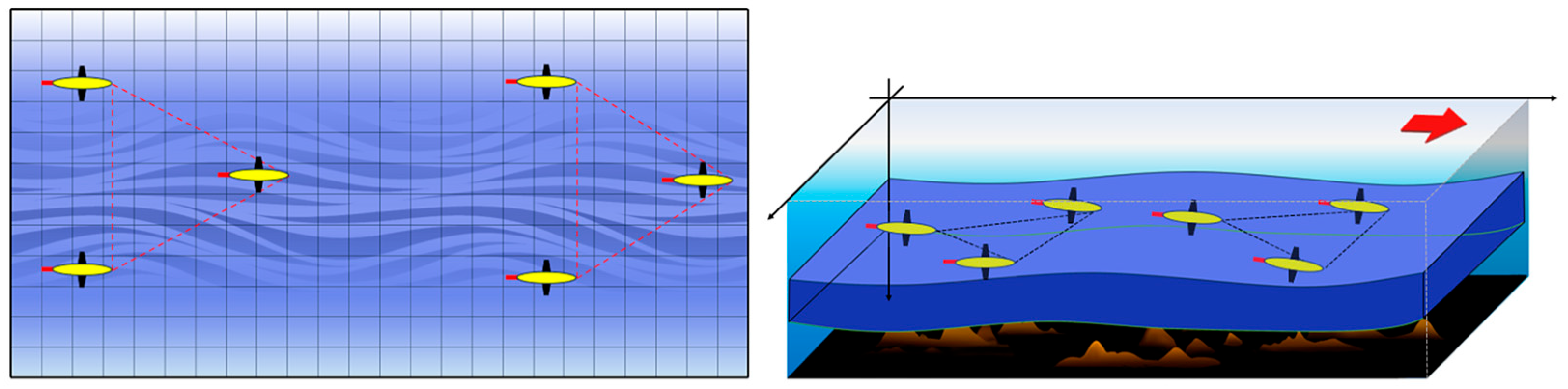
2.2.1. Application Scene

Figure 2 presents the high-maneuvering underwater vehicle engineered through this research, featuring an axisymmetric hydrodynamic form with a 520 mm diameter. To achieve the target 3-knot operational capability (1.54 m/s equivalent), hydrodynamic optimization requires rigorous quantification of viscous drag at a 1.5 m/s cruise velocity. Given the vehicle’s experimentally validated drag coefficient ( C d   = 0.38), the parametric formulation governing hydrodynamic resistance derives from the following fundamental fluid dynamic principle:
D = 1 2 C D ρ V 2 S n
where D represents the hydrodynamic drag force under investigation. The dimensionless resistance coefficient C D is empirically determined as 0.38 through rigorous experimental validation. Fluid density ρ is defined as the reference seawater density (1000 kg/m3). Operational velocity V is prescribed at 1.5 m/s for hydrodynamic performance evaluation, while S n denotes the high-maneuvering underwater vehicle ‘s effective frontal cross-sectional area orthogonal to the flow vector.
The hydrodynamic resistance at 1.5 m/s operational velocity yields 98.342 N, with the dual-propeller system’s symmetrical thrust distribution requiring bisected parameter allocation for propulsion system optimization.

2.2.2. Establishment of Propeller Mechanical Model

We have optimized the NACA 6 series propellers mainly used in small and medium-sized vehicles. The propeller design is derived from the strict quantification of the blade thickness distribution and the chord length radial gradient. The parallel engineering requirements specify the determination of the ratio of thickness to diameter, so that hydrodynamic thickness prediction can be carried out through the van Mannen–Trost semi-analytical framework:
t D = t t i p D + f x t 0 D t t i p D
The dimensionless parameter quantifying blade tip thickness relative to propeller diameter governs diameter selection through the following principles:
t t i p D = 0.0035 D < 3.0 m 0.0045 D 3.0 m
Thickness fraction relationship:
t 0 D = 100 D C 1 P D 280400 Z . N . σ c 3
where σ c represents material permissible stress (Pa), PD the shaft power (W), and N rotational velocity (rpm). Rigorous investigations [19,20,21,22] confirm that invariant power and rotational speed impose an inverse proportionality between propeller diameter and pitch magnitude. Although variations in radial pitch distribution exert negligible influence on open-hydrodynamic efficiency, they profoundly modulate cavitation susceptibility.
Operational conditions induce pressure depression on the blade’s suction surface, potentially attaining sub-vapor thresholds that catalyze explosive phase transitions, i.e., hydrodynamic nuclei undergo rapid volumetric expansion into vapor cavities. This cavitation mechanism compromises propeller integrity and operational efficiency, with the critical pressure boundary defined by the temperature-dependent vapor pressure (saturation vapor pressure).

2.2.3. Cavitation Initiation Analysis with Correlation Derivation

For hydrodynamic analysis, consider uniform inflow velocity V 0 impinging on the blade section at angle of attack α k . The suction surface manifests accelerated flow ( V b > V 0 ) with concomitant pressure reduction ( p b < p 0 ), while the pressure surface displays flow deceleration ( V b < V 0 ) and pressure elevation ( p b > p 0 ). By applying Bernoulli’s theorem to streamline-connected points A (upstream) and B (suction surface),
p b + 1 2 ρ V b 2 = p 0 + 1 2 ρ V 0 2
Let V 0 represent the flow velocity at reference point A and p 0 its corresponding static pressure.
p 0 p b = 1 2 ρ ( V b 2 V 0 2 )
Normalizing the governing equation by 1 2 ρ V 0 2 yields the dimensionless pressure reduction coefficient
ξ = p 0 p b 1 2 ρ V 0 2 = ( V b V 0 ) 2 1
In the formula, ξ is called the pressure reduction coefficient.
Pressure distribution analysis across fluidic cross-sections demonstrates that zones exhibiting ξ < 0 manifest supra-ambient pressures (surpassing p 0 ), while ξ > 0 indicates sub-ambient pressure regions. Cavitation initiation at nodal point B is classically determined by the depressurization threshold reaching p v —the thermodynamic saturation vapor pressure specific to the aqueous medium. Consequently, the cavitation threshold at locus B is rigorously defined by the inequality
p b p v
σ = p 0 p v 1 2 ρ V 0 2

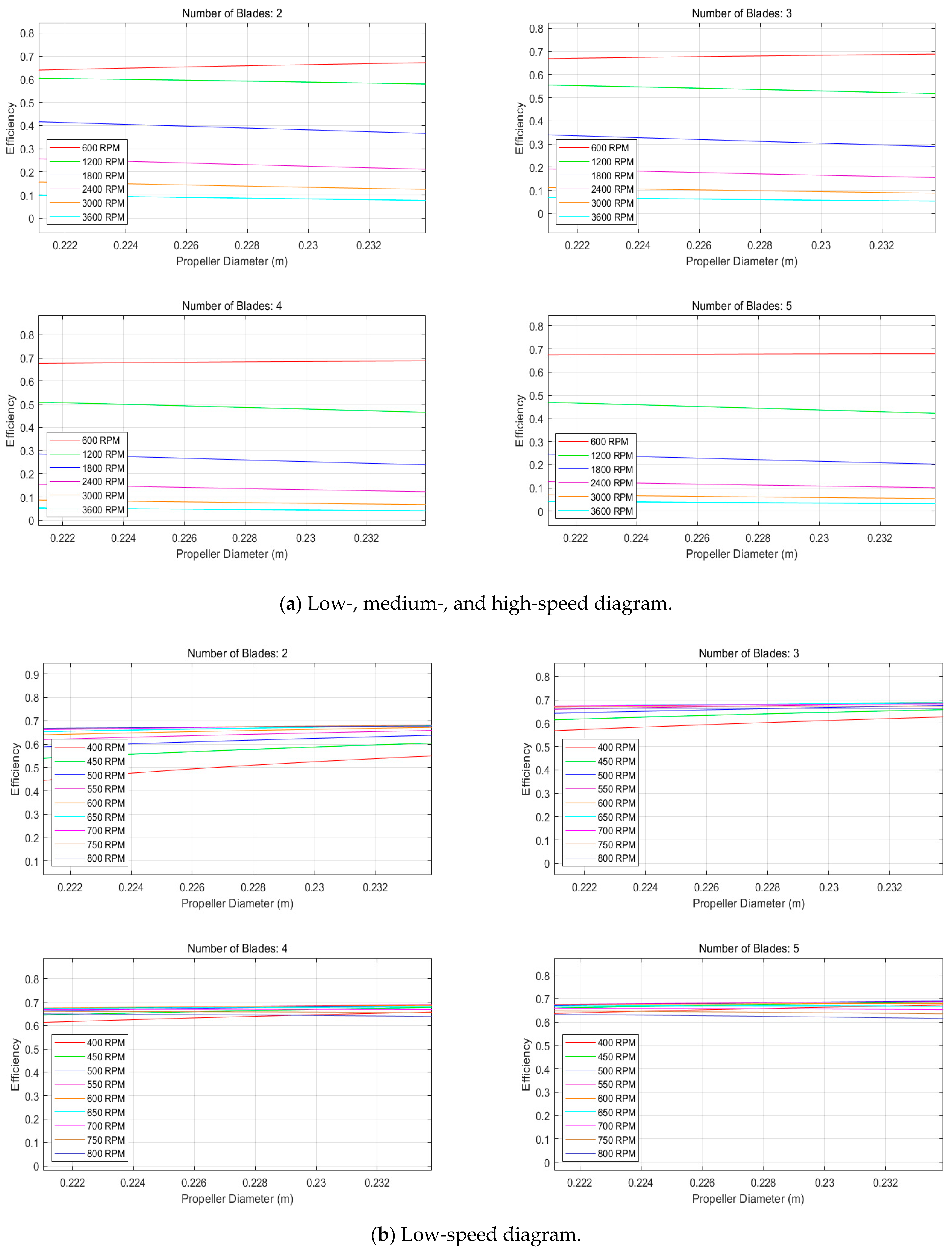
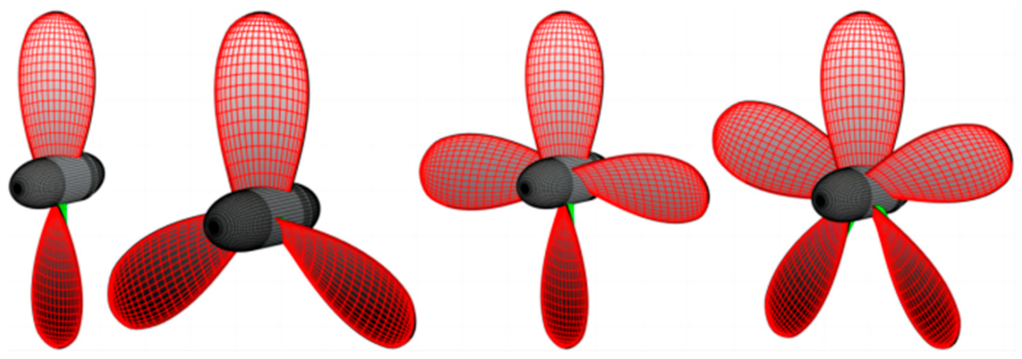
2.2.4. Screening and Optimization of Propeller Mechanical Geometric Parameters

Hydrodynamic interrogation elucidates that cavitation nucleation at locus B is effectively inhibited when the depressurization coefficient satisfies ξ < σ . Furthermore, multivariate correlational analysis between propeller pitch ratio P/D and BP1/2 (with BP representing absorbed horsepower coefficient) across divergent cavitation indices, as depicted in (15), permits precise quantification of parameter R.
B p = N P D 1 2 V A 2.5
The coefficient C1, derived via regression analysis of the 0.7R pitch ratio, integrates blade count Z and rotational speed N:
C 1 = 5516.2036 11129.9154 P D 0.7 R + 10004.4887 P D 0.7 R 2 3459.9152 P D 0.7 R 3 + 100.5205 P D 0.7 R 6
According to basic research [22,23,24], the propeller diameter is limited to 90% of the maximum size of the mother ship. This engineering specification limits the rotor size to 234 mm when integrated with a 0.26 m autonomous underwater vehicle platform. The standard practice recommends a hub diameter ratio (h/d) of 0.15 to 0.2, which yields the hub size range of 35.1 to 46.8 mm. Using MIT ‘s OpenProp numerical simulation toolkit—an implementation of lift line theory—our hydrodynamic modeling reveals the basic interdependence between thrust and efficiency. Under the operating reference of 1.5 m/s, the propulsion of 49.171 N is required, the hub diameter is 0.351 m, and the blade configuration is 2 to 5. The parameter analysis systematically evaluates the propulsion efficiency at different rotational speeds.
Figure 3 illustrates the interdependence between η-RPM. In Figure 3a, the speed relationship is illustrated according to line color. Although we obtain the data as the number of features in the region, we can still observe the corresponding relationship using the data. It is not difficult to see that the efficiency is the highest at about 600 rpm. Under the condition that the blade is unchanged, the efficiency decreases with the increase in the rotational speed. We conclude that NACA 6 series blades may achieve better efficiency at low speeds. The NACA 6 series blades show that the hydrodynamic performance is not ideal at high and medium speeds. We conclude that the NACA 6 series blades may achieve better efficiency at low speeds. We then perform a low-speed analysis of the obtained NACA 65A010 blade to obtain the optimal speed threshold. In the low-speed operation, as shown in Figure 3b, the hydrodynamic efficiency reaches a peak within the defined geometric boundary. This optimization of operating parameters provides key guidance for marine propulsion systems and balances energy conservation and dynamic response capabilities. In the figures, different colors represent different speeds of blade rotation and each color corresponds to the speed relationship.
After finding the appropriate speed threshold, OpenProp is used to modify some parameters, and the optimized propeller geometry shown in Figure 4 is generated. The red line shows the bending of the straight line in the region, and the intersection point is the position where the bending change is the largest.
Based on the numerical prediction of OpenProp, the hydrodynamic efficiency curve of the blade is shown in Figure 5. In Figure 5, the hydrodynamic performance curves of NACA 65A010 series two-blade, three-blade, four-blade and five-blade propellers are presented. The horizontal axis advance coefficient Js reflects the working condition through the correlation of advance speed to rotation speed and propeller diameter. The vertical axis covers green hydrodynamic efficiency η, blue thrust coefficient KT and red torque coefficient KQ. Increasing rotational inertia demonstrates an inverse correlation with both torque and thrust coefficients, which exhibit gradual decline. The hydrodynamic efficiency shows a nonlinear dependence on the rotational inertia, which gradually decreases after the initial increase. The five-blade propeller of the NACA 65A010 blade reaches a peak efficiency of 69.01% under the same conditions, which is superior to other configurations.

3. Theory of Sound Field Solution

Oberai et al. [2,3,25] derived the variational form of the Lighthill acoustic analogy. The strong variational form of the equation is as follows:
Ω ( 2 t 2 ( ρ ρ 0 ) c 0 2 2 x i x j ( ρ ρ 0 ) 2 T i j x i x j ) δ ρ d x = 0 δ ρ
where δ ρ is the test function. Green’s formula is used to integrate the spatial derivative by parts, and the weak variational form is obtained as follows:
Ω ( 2 t 2 ( ρ ρ 0 ) + c 0 2 x i ( ρ ρ 0 ) δ ρ x i + T i j x i δ ρ x i ) d x = r ( c 0 2 x i ( ρ ρ 0 ) n i + T i j x j n i ) δ ρ d x
Here, we define the total stress tensor as
i j = ρ v i v j + ( p p 0 ) δ i j τ i j
Substitute it into the equation as
Ω ( 2 t 2 ( ρ ρ 0 ) δ ρ + c 0 2 x i ( ρ ρ 0 ) δ ρ x i ) d x = Ω T i j x i δ ρ δ x i d x + r T i j x j n i δ ρ d x
The above equation is the variational equation of Lighthill’s acoustic analogy, and the right side of the equation is the body sound source and the surface sound source. The body sound source includes three parts: vortex source term, viscous source term, and entropy source term. When the equation is used to solve the propeller noise, the quadrupole source is included in the body sound source, and the monopole and dipole sources are included in the surface sound source.

4. Simulation

4.1. Computational Simulation Environment Configuration

In this study, XFLOW 2023 software and Fluent simulation were used to simulate the fluid dynamics of the wing-beat UAV inspired by butterflies. XFLOW is mainly selected because of its particle-based computational model, which can efficiently and accurately deal with highly unstable and complex flow phenomena and effectively solve the problem of fluid–structure interaction (FSI). The k-ε SST turbulence model was simulated by Fluent, and the enhanced wall function was used to manage the wall surface. In addition, an adaptive time step control is introduced to ensure the stability of the solution process. According to the conclusion in Section 2, this aspect mainly verifies the simulation analysis of the optimal speed threshold of different blade numbers. In compliance with national regulations outlined in CCAR-36—R2, “Aircraft Type and Airworthiness Certification Noise Regulations” [7], the environmental parameters were configured as presented in Table 1.

4.2. XFLOW Simulation

4.2.1. Simulation Parameter Setting

Because of its use of basic numerical methods, the complete Lagrangian methodology is a meshless computational fluid dynamics paradigm, obtained through the discrete Lagrangian reference frame using continuous tracer transport monitoring to analyze flow dynamics. Therefore, it is characterized by independent grids, requiring only the setting of the grid number, and 8,192,000 independent grids are set in the slice for simulation calculation, as shown in Figure 6. It shows the flow field distribution of the blade when it moves in the fluid. The cooler the color tone, the lower the flow velocity in the region, and the warmer the color tone, the higher the flow velocity in the region. According to the color, we can infer that the bright green area in the center of the blade exhibits special phenomena such as a pressure change or vortex.

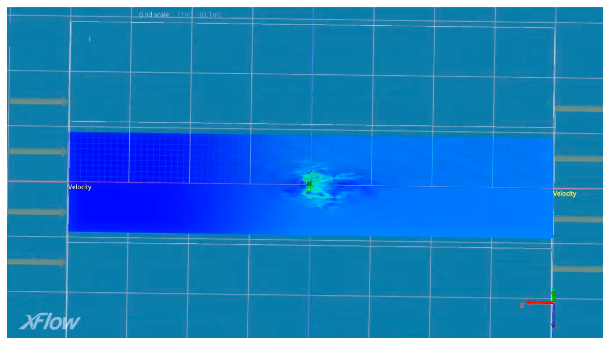
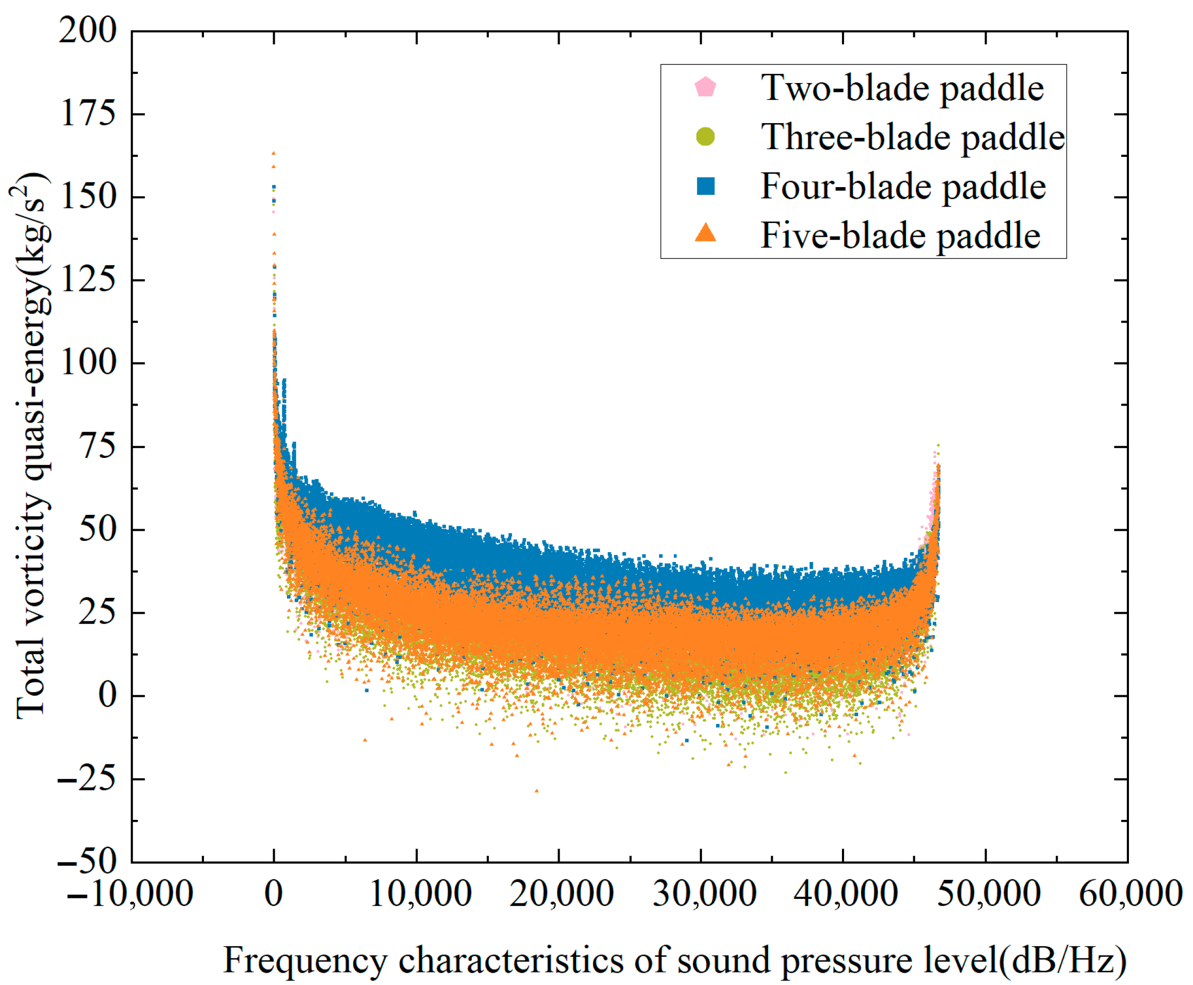
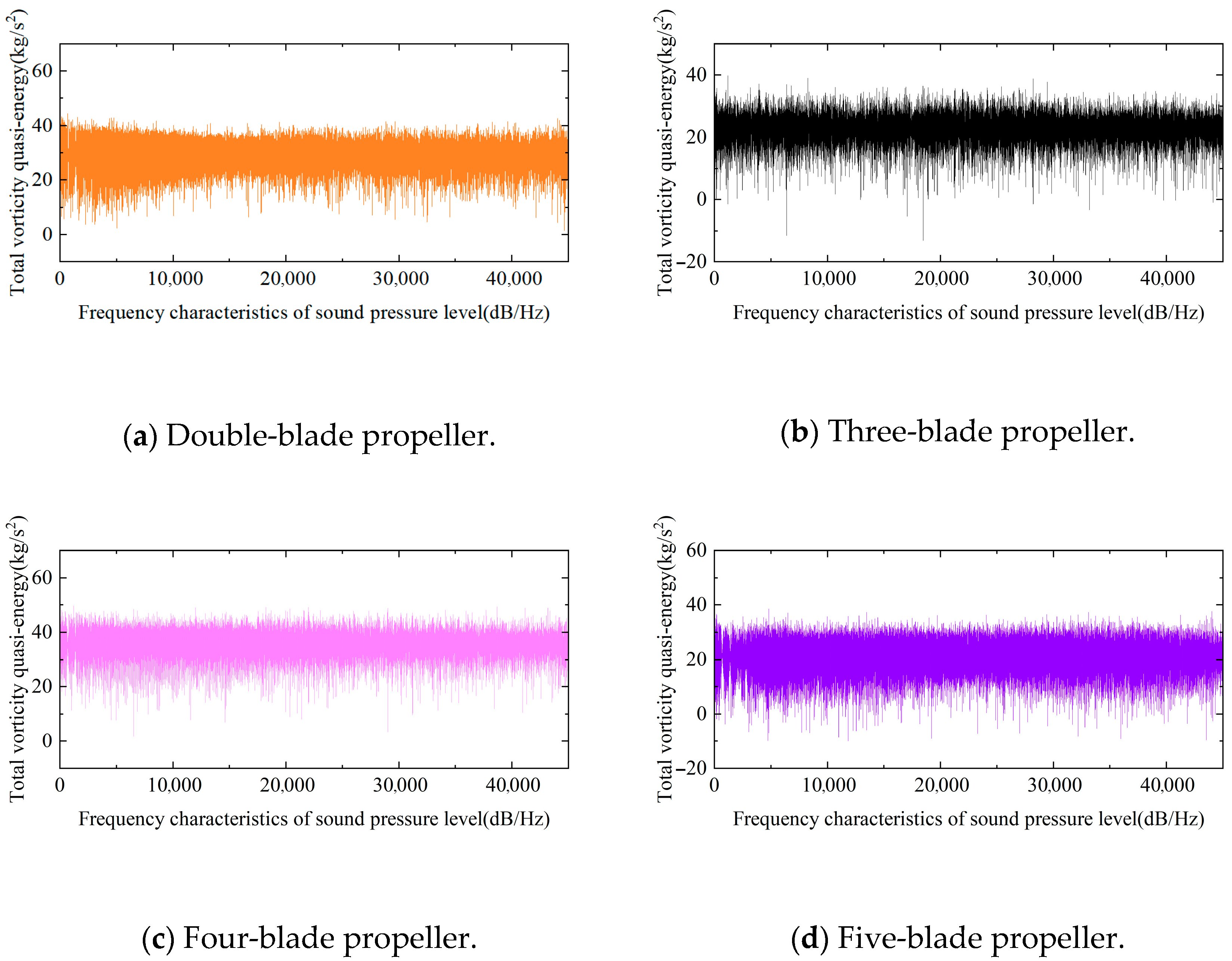
4.2.2. Numerical Results Analysis

The simulated data was processed using fast Fourier transform (FFT) to generate the FFT diagram, as illustrated in Figure 7. It shows the corresponding relationship between sound pressure level and energy, and different colors represent different numbers of blades. It can be seen from the figure that the data results of each blade are concentrated and stably distributed, and there are fluctuations within a reasonable range. The results indicate that the noise produced by the propeller during operation exhibits both periodicity and persistence, with stable noise levels and no significant fluctuations. From the diagram, it can be seen that the five-blade propeller performs best at 500 rpm and generates the lowest noise compared with the best speed distribution of other blades.
By integrating propeller efficiency predictions with a comparative analysis of the acquired data, the instantaneous vorticity of the blades and the sound pressure level (SPL) scatter plot (Figure 8) were meticulously examined. The findings reveal that, under standard environmental conditions, all blades operate at their optimal rotational speeds, with the five-blade propeller achieving the lowest noise levels at 500 RPM, as depicted in Figure 7d, and demonstrating a hydrodynamic efficiency of 69.01%.

4.3. Fluent Simulation
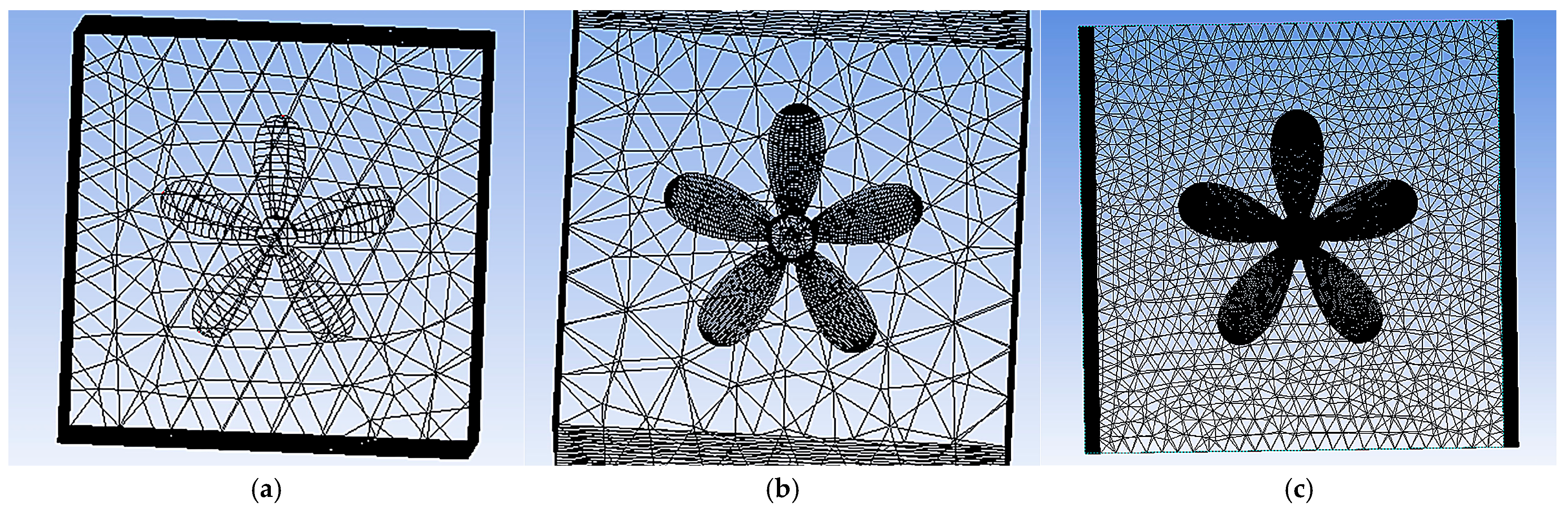
4.3.1. Meshing

After the calculation domain setting is completed, the grid is divided. In this paper, the number of grids progresses from small to large. Fluent Meshing is selected as the pre-processing software for this simulation. The grid convergence index is used to verify three sets of grids with different sizes. The grid convergence coefficient R G is
R G = S 3 S 2 S 2 S 1
Among them, S 1 , S 2 , and S 3 correspond to the number of grids from small to large, respectively. In order to facilitate this distinction, they are marked as Mesh1, Mesh2, and Mesh3 respectively. The specific division results are shown in the Figure 9.

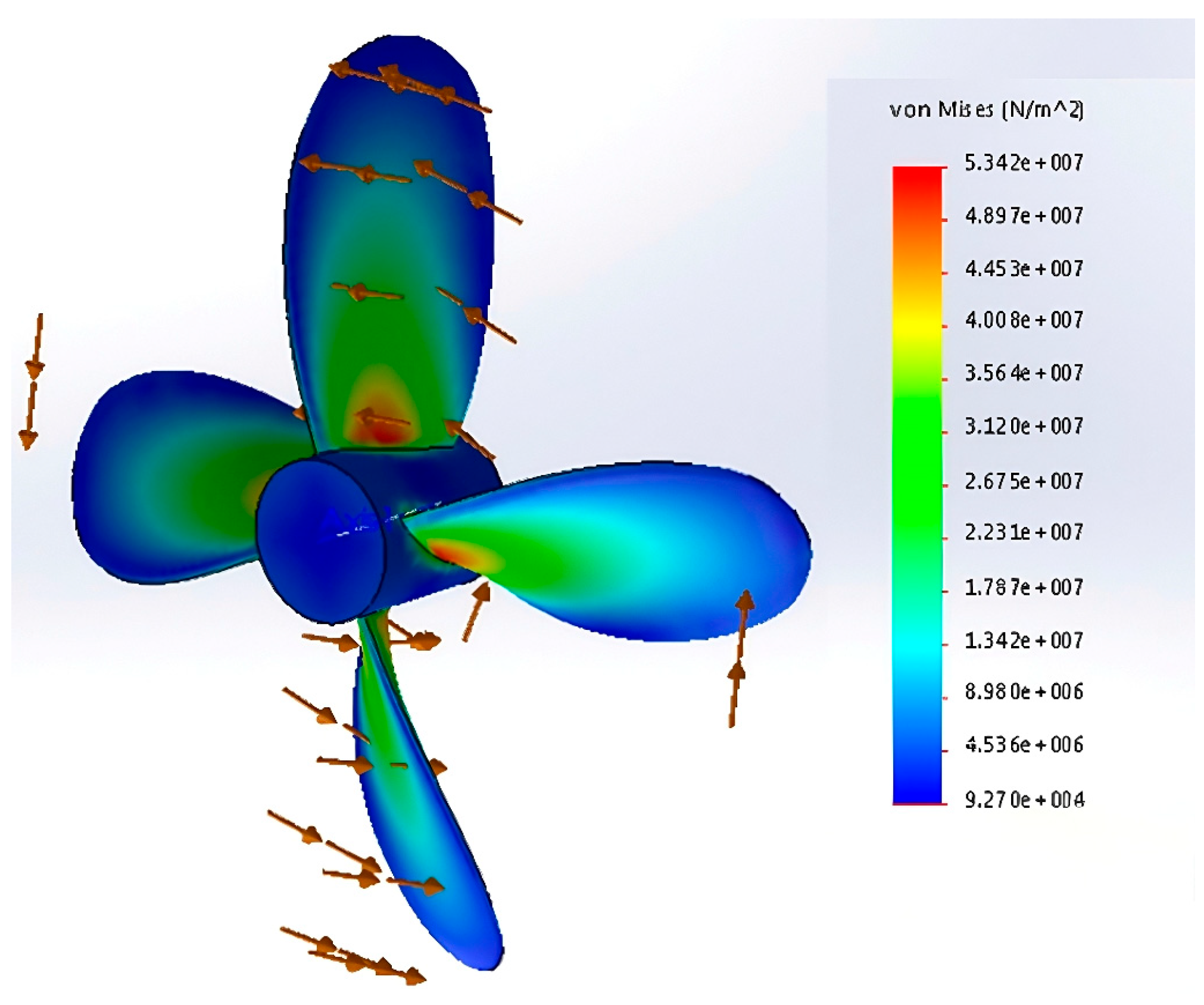
4.3.2. Numerical Simulation

Figure 10 shows the simulation results, showing the force and flow field characteristics of the blade in the fluid. It can be seen from the color distribution in the figure that the pressure values in different regions are different. The pressure in the red region is relatively high, and the pressure in the blue region is low. The direction and size of the arrow indicate the direction and size of the fluid force, reflecting the force distribution of the blade during operation. Using the results, we can analyze the causes of the noise.

4.3.3. Analysis of Numerical Results

The simulated data are processed by fast Fourier transform (FFT), and the FFT diagram is generated, as shown in Figure 11. Different colors represent different numbers of blades. From the diagram, it can be observed that the noise of the twin-blade propeller fluctuates significantly in some frequency bands; the overall fluctuation amplitude of the three-blade propeller noise is average, and the noise value of the four-blade propeller is higher at some frequencies. The noise of five-blade propeller is relatively stable. Numerically, the three-blade propeller displays a relatively low noise value in a wide frequency range and performs better from the perspective of reducing noise. The difference between the five-blade propeller and the three-blade propeller is not significant.
By comparing the results with those in Section 4.2, it can be concluded that the noise of the three-blade propeller is the lowest under the optimal speed threshold of different blades, and the difference between the five-blade propeller and the three-blade propeller is not significant.

5. Test Verification

5.1. Test Object

Based on the three-dimensional model generated at the midpoint of OpenProp, 3D printing technology is used for printing, and the finished product is shown in Figure 12.

5.2. Monitoring Equipment

In this study, the Delixi electrical decibel instrument (model: DECEMSMH1130A) was selected as the aerodynamic noise measuring instrument, which met the national GB/T 3785-2008 “decibel meter level and scale” secondary standard. The device exhibits the advantages of high precision, strong anti-interference ability, and fast response. It can measure the dynamic range of 30~130 dB with high precision.

5.3. Test Environment

In order to ensure the authenticity and validity of the noise data, the experiment was carried out in a closed laboratory, with reference to the relevant provisions included in Section 4.1.

5.4. Noise Evaluation Method

In order to accurately assess the noise of the propeller, the noise analysis uses the A-weighted sound pressure level, the equivalent continuous sound pressure level, and the NR curve. These methods are the standards for processing noise data at home and abroad. In this paper, the results are verified by the A-weighted sound pressure level method.
The A-weighted sound pressure level is a measure of human perception of sound. The sensitivity of the human ear to different frequencies is different, and the response to the middle frequency band is more sensitive, while the low frequency and high frequency bands are less sensitive. The A weighting method is the most commonly used weighting technique, which is achieved by adjusting the sound pressure value at a specific frequency. The specific formula is as follows:
S P L = 20 lg P P r e f

5.5. Test Results

The optimized propeller is rotated within its optimal speed threshold, and the obtained data is plotted in Figure 13. Figure 13 shows the surf model diagram of NACA 65A010 blade noise data. The horizontal axis is the number of blades and the time, the vertical axis is the sound pressure level, and the right color bar represents the color correspondence of different sound pressure levels.
It can be seen from the figure that as the number of blades gradually increases from two blades to four blades, the overall sound pressure level shows an upward trend. From the average point of view, when the number of blades is three and five, the sound pressure level is relatively low, which indicates that the corresponding noise reduction effect is better.
From the experimental results, it can be seen that from the time dimension, the sound pressure level fluctuates under different blade numbers in the whole time span of 60 s. However, on the whole, when the number of blades is small, the fluctuation range of sound pressure level is relatively small, and the value is low.

5.6. Data Comparison

There are both similarities and differences between the experiment and the two software analyses, as shown in Table 2. The commonness is that for both the experiment and the simulation, the corresponding values of different blade types are different, but the overall trend is the same. The four-blade propeller also displays the highest mean value, and the three-blade propeller exhibits the lowest mean value. Their differences are reflected in many aspects. In terms of the numerical results, the average value of each blade type obtained by the experiment is generally higher than the analysis results of the simulation software, which may be due to the actual physical environment factors in the experiment, the measurement error, and the deviation between the simulation software based on the set algorithm and the model hypothesis and the actual operation. In terms of implementation, the experiment is actually operated and measured in a real environment, involving specific equipment, materials, and physical processes, while the simulation is generated by software based on mathematical models and algorithms, without actual physical construction and operation.

6. Conclusions

In order to improve the hydrodynamic efficiency and stealth performance of underwater vehicles in the Kuroshio current, this study used the OpenProp open source framework to optimize the propeller design of the NACA 65A010 airfoil and its optimal rotation speed threshold. The LBM–full Lagrangian-LES method was used for simulation prediction and experimental verification. The following key conclusions are drawn: (1) The NACA 65A010 airfoil propeller is collaboratively optimized by OpenProp and XFlow methods. Through the lattice Boltzmann method and full Lagrangian–LES multi-physics modeling, the double-optimal balance of 69.01% water efficiency and 22.89dB minimum noise (simulation value) is accurately realized, which improves efficiency by 15% and reduces noise by 10–15% compared with the results for the traditional design. (2) The nonlinear coupling effect between the number of blades and the rotational speed is quantified by the system. The five-blade propeller effectively delays the cavitation initiation by dispersing the single-blade load at a speed of 500 RPM. However, when the number of blades exceeds five, the efficiency will plummet by 10–15% due to the intensification of turbulence in the flow field, which provides a multivariable collaborative optimization criterion of “blade number–rotational speed–cavitation noise” for propeller design. (3) Based on the Lighthill acoustic analogy variational form, the transient fluctuation of the pressure field is analyzed by XFLOW Lagrangian particle simulation. The sound pressure level is calculated by combining the SST k-ε turbulence model of Fluent, and the noise spectrum is generated by fast Fourier transform (FFT). The noise characteristics of the body source (vortex source, viscous source) and the surface source (monopole, dipole) are extracted.
In the future, we will persist in advancing propeller optimization designs with digital twin technology. Moreover, the techniques outlined in this study can be applied to various domains, including high-power aircraft stealth, tank noise analysis, and other military or civilian sectors, offering substantial contributions across diverse fields.

Author Contributions

Conceptualization, R.Z. and T.Z.; methodology, B.H.; software, R.Z.; validation, Z.T., H.Z. and T.Z.; formal analysis, C.Z.; investigation, T.Z.; resources, B.H.; data curation, Z.T.; writing—original draft preparation, H.Z.; writing—review and editing, B.H.; visualization, Z.T.; supervision, R.Z.; project administration, Z.T.; funding acquisition, R.Z.; development of experimental scheme, R.Z. and C.Z.; implementation of experimental scheme, Z.T. and C.Z. All authors have read and agreed to the published version of the manuscript.

Funding

This work is supported by the Tianjin Municipal Enterprise Technology Commissioner Project (Grant No.: 24YDTPJC00860); the Tianjin Municipal Natural Science Foundation Diversified Investment Project (Grant No.: 24JCQNJC00290); the China Postdoctoral Science Foundation (Grant No.: 2025M770292).

Institutional Review Board Statement

Not applicable.

Informed Consent Statement

Not applicable.

Data Availability Statement

The original contributions presented in this study are included in the article. Further inquiries can be directed to the corresponding author(s).

Acknowledgments

The authors also would like to express their sincere thanks to L. Ma and J. Chen for their helping to revise the grammar.

Conflicts of Interest

Author Tongrui Zhang was employed by the company Tianjin Hanhailanfan Marine Technology Co., Ltd. The remaining authors declare that the research was conducted in the absence of any commercial or financial relationships that could be construed as a potential conflict of interest.

References

  1. He, B.; Wang, J.; Zhang, R.; Wang, X.; Wan, X.; Yang, Y. Efficiency evaluation of underwater glider fleet based on Fuzzy-AHP-ADC model. Expert Syst. Appl. 2025, 271, 126685. [Google Scholar] [CrossRef]
  2. Ortolani, F.; Capone, A.; Dubbioso, G.; Pereira, F.A.; Maiocchi, A.; Di Felice, F. Propeller performance on a model ship in straight and steady drift motions from single blade loads and flow field measurements. Ocean Eng. 2020, 197, 106881. [Google Scholar] [CrossRef]
  3. Giulio, D.; Roberto, M.; Fabrizio, O.; Andrea, D.M. Numerical analysis of marine propellers low frequency noise during maneuvering. Part II: Passive and active noise control strategies. Appl. Ocean Res. 2022, 106, 102461. [Google Scholar] [CrossRef]
  4. Zhou, Y.; Chen, W.Z. Research on ground effect of ducted fans of VTOL UAVs. J. Unmanned Undersea Syst. 2023, 31, 942–948. [Google Scholar] [CrossRef]
  5. Zhang, Z.R.; Luo, K.; Qin, K. Design method for low specific speed axial flow pump for high-speed undersea vehicles. J. Unmanned Undersea Syst. 2024, 32, 130–138. [Google Scholar] [CrossRef]
  6. Zhao, X.Y.; Wu, T.L.; Lin, X.H.; Wu, J.G.; Zhang, M.G. Research on propeller cavitation suppression based on pump jet rectification mechanism. J. Unmanned Undersea Syst. 2022, 28, 410–419. [Google Scholar] [CrossRef]
  7. Cheng, H.Y.; Huang, J.L.; Han, C.Z.; Lei, T.T.; Ji, B. Investigation of the risk of cavitation erosion on propeller blade surface with different cavitation numbers. Eng. J. Wuhan Univ. 2023, 12, 1527–1535. [Google Scholar] [CrossRef]
  8. Tan, K.L.; Xie, W.; Liu, Z.Y.; Xie, X.C.; Wang, W.G.; Liu, Q. Research on the influence of propellers on ship maneuvering hydrodynamics under different speeds. Ocean Eng. 2024, 4, 141–149. [Google Scholar]
  9. Wen, X.F.; Cai, B.G.; Huang, J.X.; Zhou, R.P. Transient response of marine propulsion shafting during ship turning operation. Navig. China 2019, 42, 72–80. [Google Scholar]
  10. Wen, X.F.; Cai, B.G.; Wang, X.D. Dynamic simulation of ship propulsion shafting system under cyclic loading. Navig. China 2021, 44, 13–19. [Google Scholar]
  11. Zou, R.H.; Hu, W.J.; Wang, H.R. CFD Simulation of aerodynamic characteristics of ducted propeller and analysis of influence of structural parameters. Fluid Meas. Control 2024, 5, 7–10. [Google Scholar]
  12. Kim, N.; Kwon, J.H.; Kim, H.; Lee, D. Propeller blade structural reliability analysis considering mixed-mode fatigue crack growth. Eng. Fail. Anal. 2024, 158, 108014. [Google Scholar] [CrossRef]
  13. Cao, Q.; Wei, K.; Nie, Y.P.; Yan, Q.; Chen, Y.H. Aeroacoustic test system design and experimental research for counter-rotating propeller. Adv. Aeronaut. Sci. Eng. 2024, 15, 148–154. [Google Scholar] [CrossRef]
  14. Aram, S.; Mucha, P. CFD validation and analysis of turning maneuvers of a surface combatant in regular waves. Ocean Eng. 2024, 293, 116653. [Google Scholar] [CrossRef]
  15. Liu, Y.G.; Fu, W.A.; Wang, H.M.; Zeng, C.J. Research on abnormal monitoring of propeller vibration force during inspection of offshore wind turbine unmanned aerial vehicle. Autom. Instrum. 2024, 1, 93–97. [Google Scholar]
  16. Zheng, S.J.; Zhou, L.; Diao, F.; Ding, S.F.; Liu, R.F. Experimental study on hydrodynamic performance of two-way propeller in cavitation tunnel. J. Ship Mech. 2024, 28, 70–80. [Google Scholar] [CrossRef]
  17. Liu, K.; Liu, Y.Q.; Lin, H.; Xiao, J.H.; Peng, H.; Lu, X.J.; Lu, H.M. Research of trans-medium strategy for unmanned aerial-undersea vehicles. J. Unmanned Undersea Syst. 2024, 32, 396–410. [Google Scholar] [CrossRef]
  18. Zhou, J.; Ma, L.; Heng, H. Simulation Analysis of variable cross-section Linetype optimization for swim-out tube in UUVs. J. Unmanned Undersea Syst. 2024, 32, 147–151. [Google Scholar] [CrossRef]
  19. Qin, Y.; Wang, G.L.; Guan, S.; Wang, Y.F.; Ding, J.H. Motion simulation of spatial sampling of mesoscale processes for underwater gliders. J. Unmanned Undersea Syst. 2022, 30, 474–484. [Google Scholar] [CrossRef]
  20. Zhang, H.W.; Wang, J.X. Fault-tolerant control of AUV thruster based on adaptive backstepping sliding mode. J. Unmanned Undersea Syst. 2021, 29, 420–427. [Google Scholar] [CrossRef]
  21. Hu, Y.; Zhang, X.P.; Wang, Q.; Luo, Z.N.; Wang, G.Q. Improved design of hovering efficiency of ducted propeller with large blade tip clearance based on grooved duct configuration. J. Aerosp. Power 2025, 150, 109226. [Google Scholar] [CrossRef]
  22. Zou, K.; Gui, M.H.; Lai, M.Y. Influence of appendages upon performance and propellers power imbalance analysis of a vessel with triple pods. Ship Ocean Eng. 2023, 6, 54–59. [Google Scholar] [CrossRef]
  23. Lu, D.S.; Sun, T.Z.; Zhang, G.Y. Numerical analysis of hydrodynamic characteristics of ducted propeller. Ship Boat 2023, 34, 102. [Google Scholar] [CrossRef]
  24. Pang, J.J.; Han, H. A calculation method of static balance of 3-blade propeller. CFHI Technol. 2023, 6, 47–51. [Google Scholar] [CrossRef]
  25. Oberai, A.A.; Roknaldin, F.; Hughes, T.J. Computation of trailing—Edge noise due to turbulent flow over an airfoil. AIAA J. 2002, 40, 2206–2216. [Google Scholar] [CrossRef]
Figure 1. Kuroshio current observation scheme with UG fleet (red arrow indicate the flow direction) [1].
Oceans 06 00048 g001
Figure 2. Schematic diagram of (a) high-maneuvering underwater glider, (b) prototype of Seaswan-I Glider, and (c) lake test of underwater glider.
Oceans 06 00048 g002
Figure 3. Prediction of blade hydrodynamic efficiency.
Oceans 06 00048 g003
Figure 4. Three-dimensional model of propeller.
Oceans 06 00048 g004
Figure 5. Variation curve of blade watering efficiency.
Oceans 06 00048 g005
Figure 6. Aeroacoustic simulation of blade (XFLOW).
Oceans 06 00048 g006
Figure 7. Leaf noise FFT curve.
Oceans 06 00048 g007
Figure 8. Scatter plot of blade instantaneous vorticity and SPL change.
Oceans 06 00048 g008
Figure 9. Three meshing results for a five-blade propeller: (a) Mesh1; (b) Mesh2; (c) Mesh3.
Oceans 06 00048 g009
Figure 10. Aeroacoustic simulation of four-blade propeller (Fluent).
Oceans 06 00048 g010
Figure 11. FFT curve of blade noise.
Oceans 06 00048 g011
Figure 12. The 3D printed product diagram.
Oceans 06 00048 g012
Figure 13. NACA 65A010 blade noise data surf model.
Oceans 06 00048 g013
Table 1. Environmental parameter settings.
Variable InitializationParameter Value
Viscosity Model k-ε SST
Enhanced Wall Treatment (EWT)
Wall Boundary Formulations
Flow Boundary ConfigurationPressure-Defined Flow Boundaries
Gauge Pressure MeasurementStandard Atmospheric Pressure
Pressure–Velocity Coupling AlgorithmCoupled
Pressure Gradient Resolution SchemeBody Force Weighted
water flow velocity2 m/s
Ambient Temperature16 °C
Humidity Level60%
Table 2. Comparison of detection values and simulation results.
Two-Blade PropellerThree-Blade PropellerFour-Blade PropellerFive-Blade Propeller
XFLOW29.1421.2835.6222.89
FLUENT29.5422.7835.5822.91
Experiment36.2334.8539.0135.23
Disclaimer/Publisher’s Note: The statements, opinions and data contained in all publications are solely those of the individual author(s) and contributor(s) and not of MDPI and/or the editor(s). MDPI and/or the editor(s) disclaim responsibility for any injury to people or property resulting from any ideas, methods, instructions or products referred to in the content.

