Article

Development of a Powered Four-Bar Prosthetic Hip Joint Prototype

1
Department of Mechanical Engineering, University of Ottawa, 800 King Edward Ave., Ottawa, ON K1N 6N5, Canada
2
Össur, Grjothals 1–5, 110 Reykjavik, Iceland
3
Faculty of Medicine, University of Ottawa, 451 Smyth Road, Ottawa, ON K1H 8M5, Canada
*
Authors to whom correspondence should be addressed.
Prosthesis 2025, 7(5), 105; https://doi.org/10.3390/prosthesis7050105
Submission received: 4 July 2025 / Revised: 11 August 2025 / Accepted: 14 August 2025 / Published: 22 August 2025

Abstract

Background/Objectives: Hip-level amputees face ambulatory challenges due to the lack of a lower limb and prosthetic hip power. Some hip-level amputees restore mobility by using a prosthesis with hip, knee, and ankle joints. Powered prosthetic joints contain an actuator that provides external flexion-extension moments to assist with movement. Powered knee and powered ankle-foot units are on the market, but no viable powered hip unit is commercially available. This research details the development of a novel powered four-bar prosthetic hip joint that can be integrated into a full-leg prosthesis. Methods: The hip joint design consisted of a four-bar linkage with a harmonic drive DC motor placed in the inferior link and an additional linkage to transfer torque from the motor to the hip center of rotation. Link lengths were determined through engineering optimization. Device strength was demonstrated with force and finite element analysis and with ISO 15032:2000 A100 static compression tests. Walking tests with a wearable hip-knee-ankle-foot prosthesis simulator, containing the novel powered hip, were conducted with three able-bodied participants. Each participant walked back and forth on a level 10 m walkway. Custom hardware and software captured joint angles. Spatiotemporal parameters were determined from video clips processed in the Kinovea software (ver. 0.9.5). Results: The powered hip passed all force and finite element checks and ISO 15032:2000 A100 static compression tests. The participants, weighing 96 ± 2 kg, achieved steady gait at 0.45 ± 0.11 m/s with the powered hip. Participant kinematic gait profiles resembled those seen in transfemoral amputee gait. Some gait asymmetries occurred between the sound and prosthetic legs. No signs of mechanical failure were seen. Most design requirements were met. Areas for powered hip improvement include hip flexion range, mechanical advantage at high hip flexion, and device mass. Conclusions: The novel powered four-bar hip provides safe level-ground walking with a full-leg prosthesis simulator and is viable for future testing with hip-level amputees.

1. Introduction

A hip-knee-ankle-foot prosthesis (HKAFP) is a wearable assistive device that contains mechanical hip, knee, and ankle joints to restore an amputee’s lost leg [1]. The current state-of-the-art passive HKAFP uses a four-bar linkage hip joint (Helix3D 7E10 from Otto Bock (Duderstadt, Germany) [2]), a microprocessor knee (e.g., C-Leg from Otto Bock [3], Rheo Knee from Össur (Reykjavik, Iceland) [4]), and an energy return ankle-foot. Some hip disarticulation (HD) or hemipelvectomy (HP) amputees may opt for a powered knee (e.g., Power Knee from Össur [5], Intuy Knee from Reboocon Bionics (Pijnacker, The Netherlands) [6], BioLeg from BionicM (Bunkyo City, Japan) [7]) and/or a powered ankle-foot (e.g., Empower from Otto Bock [8]). These four prosthetic joints are the only powered joints on the market.
HD and HP amputees lack the musculature to directly move their prosthetic leg [9]. Therefore, HD and HP amputees use their trunk and pelvis to generate prosthetic leg momentum [9,10]. Sagittal pelvic tilt is a tiresome gait compensation that reduces gait efficiency. HD and HP amputees using a prosthesis require more than double the metabolic cost [11,12,13,14,15,16,17,18] and walk at approximately half the speed compared to able-bodied people [12,13,18,19].
Current prosthetic hip joints on the market are passive. Most joints are single-axis (e.g., 7E series hips from Otto Bock [20,21,22,23,24]), and several use four-bar linkages (e.g., 7E6 from Wonderful Rehabilitation Device Technology (Shijiazhuang, China) [25], Helix3D from Otto Bock [26]). HD and HP amputees, fitted with passive prostheses, exhibit slow gait with low hip and knee flexion-extension ranges and lower limb instability because they lack the joint moments normally provided by intact limb musculature [9,27,28].
In lower limb prostheses, four-bar linkages are employed to enhance stance phase stability and to achieve good prosthetic cosmesis [2,26,29,30,31,32,33,34,35,36]. Four-bar joints can change lengths within their range of motion (ROM) and therefore provide limb-shortening in the swing phase to increase toe clearance [19,30,33,35,36,37]. Single-axis joints do not possess these advantages.
An actuator coupled with a prosthetic hip joint (i.e., a powered hip) would provide augmenting hip flexion-extension moments to overcome energy-consuming gait compensation and increase lower limb stability. Compared to passive lower limb prostheses, powered lower limb prostheses facilitate gait and increase gait symmetry [38,39,40,41,42,43,44,45,46,47,48,49,50,51].
Currently, there is no viable power hip on the market. Six powered hip prostheses are reported in the literature; however, they are still undergoing prototyping or benchmark testing and have not yet reached the clinical trial stage [12,51,52,53,54,55]. Four of these powered hip prototypes demonstrated poor cosmesis and difficulties in sitting [12,51,52,53]. Two of these powered hip prototypes were developed in parallel with the powered four-bar hip presented in this paper [54,55]. These prototypes consisted of a two-pulley system driving a single-axis joint with the motor placed at the bottom pulley [54,55]. They showed robustness with mechanical testing at 100 kg body weight and successful walking with able-bodied participants using an HKAFP simulator [54,55].
Since four-bar linkage joints have advantages over single-axis joints, research should investigate combining a motor with a four-bar linkage to power the prosthetic leg. Such a joint would have varying output torques due to the four-bar linkage’s varying mechanical advantage. Therefore, the four-bar linkage mechanical advantage curve could be configured over the joint’s motion range to provide high torques at joint angles most prone to limb instability.
This paper details the mechanical design, prototyping, and testing of a novel powered four-bar prosthetic hip joint that can be integrated into an HKAFP. The powered four-bar hip demonstrated body weight support and a steady gait pattern with able-bodied participants using a wearable HKAFP simulator. Furthermore, the device successfully met size, cosmesis, and prosthetic shortening design requirements. Therefore, the powered four-bar hip advances HKAFP technology, which contributes to HD and HP amputee quality of life.

2. Materials and Methods

This section lists powered four-bar hip design requirements and presents the design and its operation. Then, this section describes the methodology used for device development: linkage geometry optimization, force and finite element analyses, prototype construction, static compression testing, and walk testing.

2.1. Design Requirements

The following design requirements guided hip joint development:
  • The powered hip must provide at least 20° extension and 130° flexion. Hip flexion-extension angles seen in unilateral transfemoral lower limb amputee walking and sitting are within this ROM [27,41,56,57,58,59,60,61,62,63].
  • The powered hip must withstand a 100 kg body weight (75th percentile male in the United States from the years 2007–2010 [64]). The 100 kg benchmark corresponds to the ISO 15032:2000 standard for HD and HP prosthesis design [65].
  • Ideally, the powered hip allows a hip-level amputee to walk with similar kinematics and kinetics as a transfemoral amputee. The Össur Power Knee 2 DC motor provides up to a 96 N-m torque, 300°/s angular velocity, and 503 W power. These motor specifications can achieve transfemoral amputee gait performance [27,56,66].
  • Device mass should not exceed 3.2 kg with the motor and battery included. The Össur Power Knee 2 (the prosthetic knee containing the actuator used in the novel powered hip) has a mass of 3.2 kg [17].
  • Device length, width, and height must each be less than 17 cm in neutral position. The 75th percentile American male, in the year 2000, had a 17 cm thigh diameter [67].
  • For optimal cosmesis, the powered hip prosthesis must fit inside the user’s clothing. There must also be no protrusion below the bottom surface of the pelvic socket in the sitting position (comfortable sitting).
  • To assist with ground clearance, the powered hip must shorten at mid-swing. Increased ground clearance reduces fall risk.

2.2. Prosthetic Hip Joint Design

SolidWorks (Dassault Systèmes SolidWorks Corporation, Waltham, MA, USA) [68] was used for all computer-aided design (CAD) design and simulations. Figure 1 presents the novel powered hip prosthesis (HKAFP thigh portion). The thigh contains the powertrain, chassis, battery, and electronics. The scope of this paper covers the powertrain only (motor and components). Bader et al. [69] previously reported on powered hip chassis development.
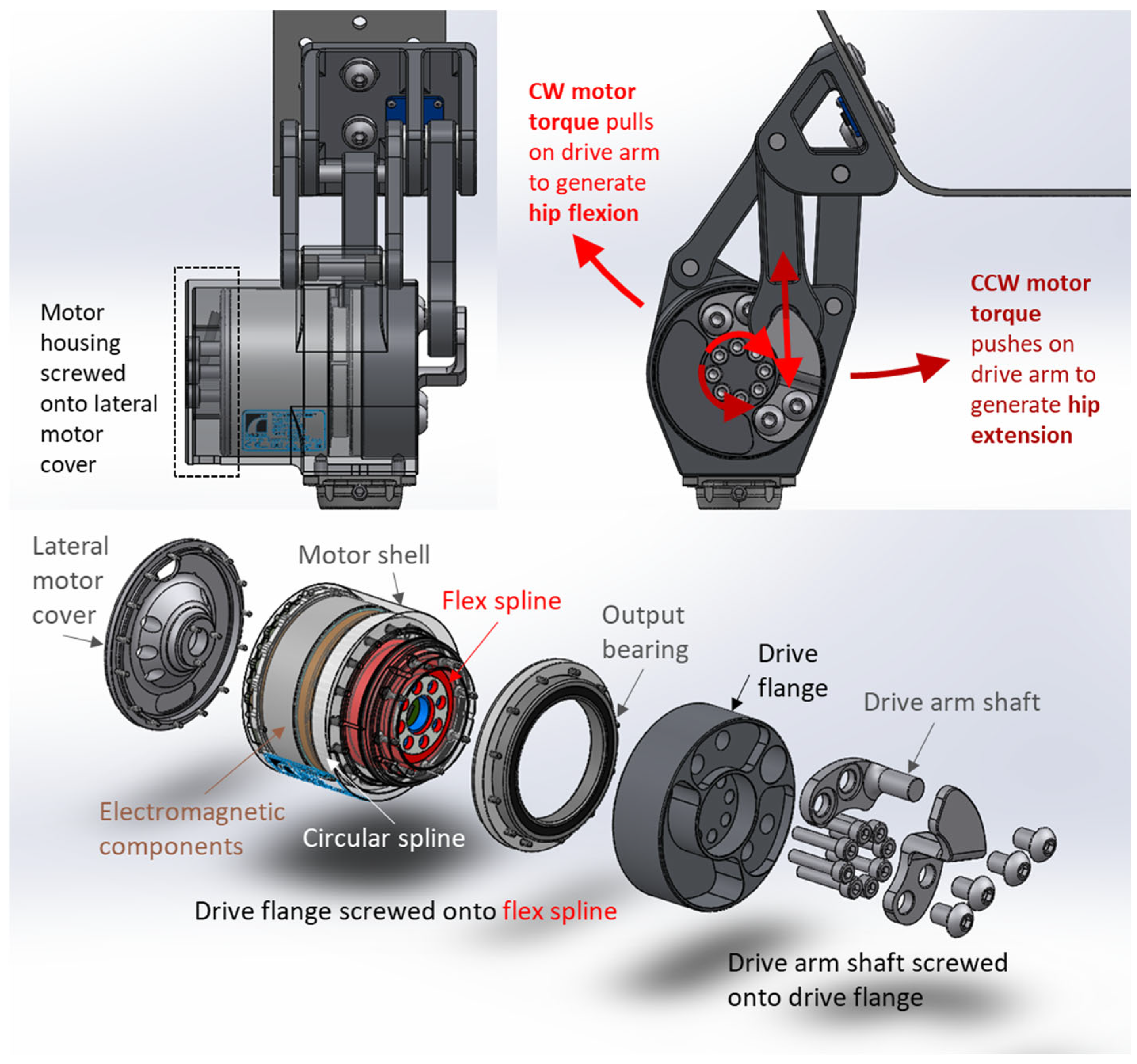
Figure 2 illustrates hip joint powertrain components and operation. The motor is placed between the two inferior revolute joints. The motor housing serves as the inferior link in a closed-loop kinematic chain. The motor lateral end is fixed to the motor housing with screws that fasten into the threaded holes of the lateral motor cover. The motor applies clockwise or counterclockwise torque to rotate the medial drive flange and provide both hip flexion and extension. A double-supported drive arm shaft is screwed onto the drive flange, and a drive arm is mounted onto the shaft. When the drive flange rotates, the shaft pushes or pulls on the drive arm, which pushes or pulls on the superior link. An upward push of the drive arm on the superior link (due to counterclockwise motor torque when viewing from the medial perspective) results in a downward push on the inferior link to generate hip extension. Similarly, a downward pull of the drive arm on the superior link (due to clockwise motor torque when viewing from the medial perspective) results in an upward pull on the inferior link to generate hip flexion.

2.3. Four-Bar Linkage Optimization

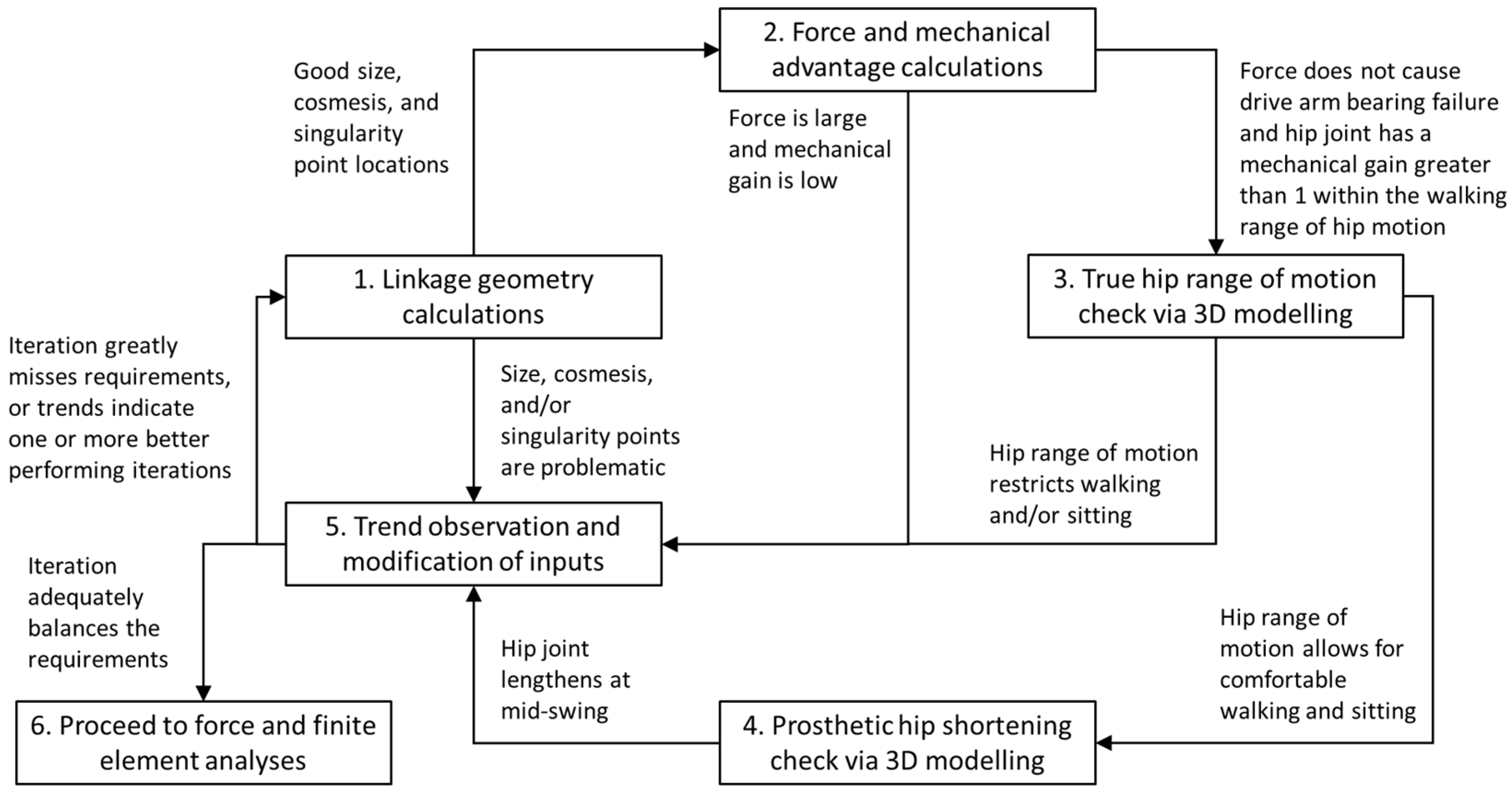
Linkage optimization determined appropriate powertrain link lengths. The optimization process consisted of repeated iterations, each of which was evaluated in up to five steps as demonstrated in Figure 3. Step 1 consisted of solving trigonometric relationships at ROM extremities with some estimates for input linkage dimensions (i.e., design variables). Appendix A.1 describes the equations used to solve for output linkage dimensions using input linkage dimensions. Step 1 was repeated if ROM, size, and cosmesis improvements could be made. Steps 2–4 involved drive arm force, mechanical advantage, and CAD model checks. Appendix A.2 details the equations used to calculate drive arm force and mechanical advantage for a fully dimensioned linkage. Steps 2–4 were carried out only if step 1 yielded satisfactory outputs. The goals of steps 1–4 were to minimize drive arm force, maximize mechanical advantage, and minimize protrusions. Completion of a few iterations allowed for step 5, trend observation, and the modification of inputs. If any of these steps yielded results that were too distant from design requirements, the iteration was ended and the next iteration restarted at step 1. When the optimal iteration (an iteration adequately balancing design requirements) was reached, the optimization process was ended, and the powertrain design process moved on to force and finite element analyses (step 6).
Figure 4 illustrates the optimized powertrain dimensions and joint motion. The optimized link lengths were 6.12 cm for the posterior link, 6.88 cm for the inferior link (distance between the two pivots on the motor housing), 7.09 cm for the anterior link, and 3.30 cm for the superior link (distance between the two pivots on the superior link). Drive arm length was 8.23 cm, and the distance from motor center to drive arm shaft center was 3.27 cm. From full hip extension to full hip flexion, the joint rotated 120°, and the actuator rotated 114°.
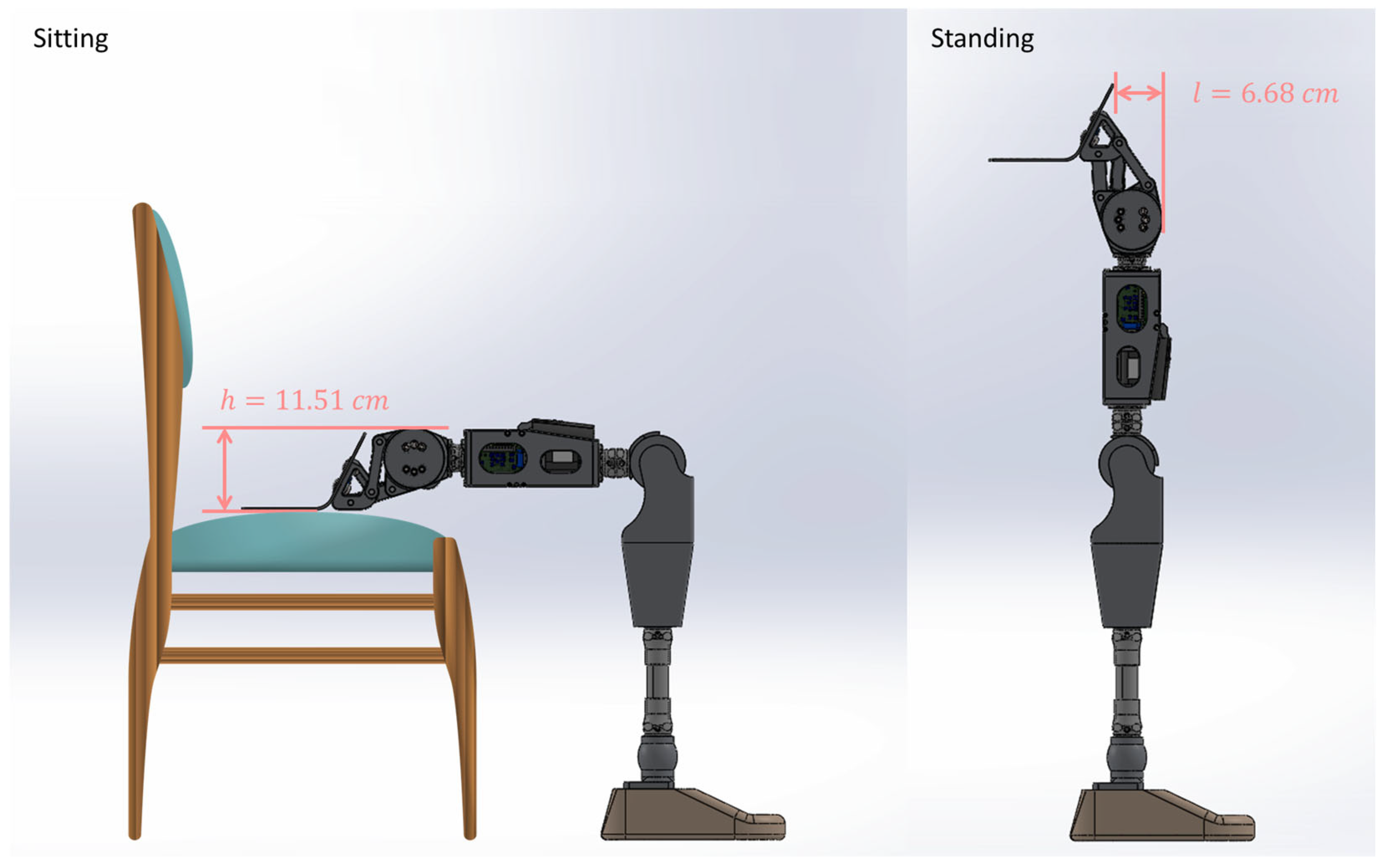
Figure 5 illustrates sitting and standing positions for a full prosthetic leg with the optimized powered four-bar hip. The device had an 11.51 cm superior protrusion in the sitting position and a 6.68 cm anterior protrusion in the standing position.
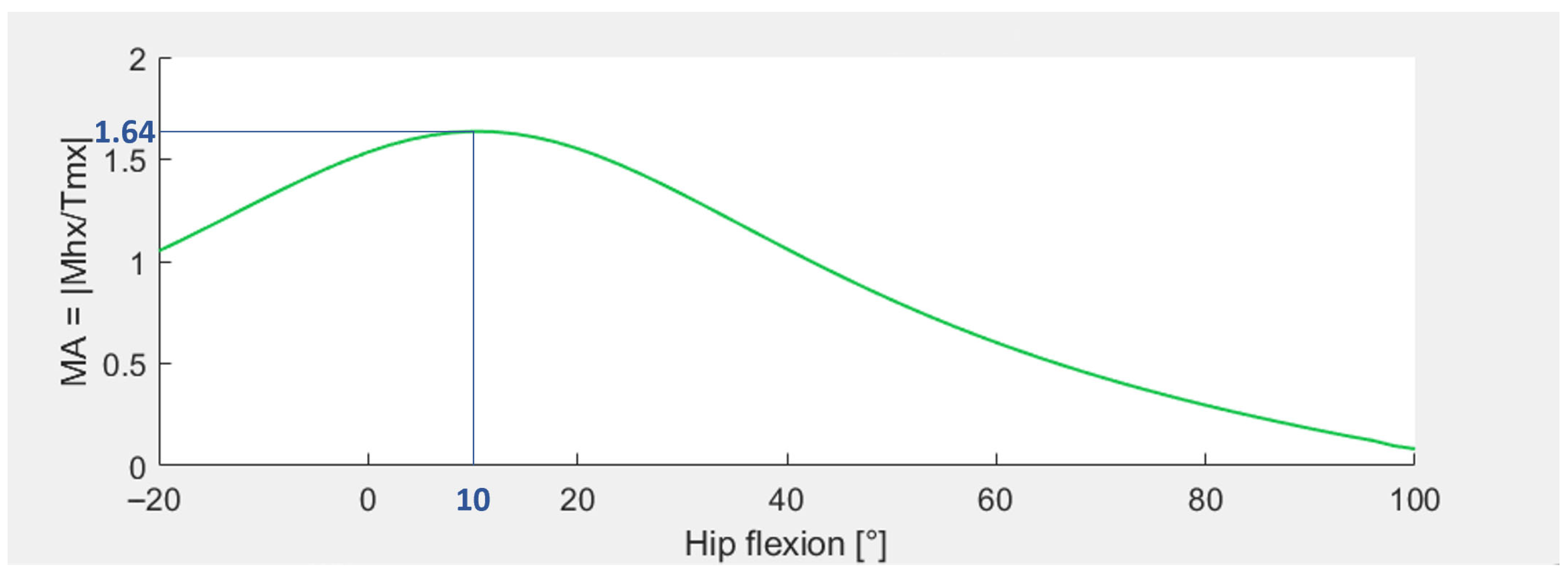
Figure 6 shows the mechanical advantage profile over the powered four-bar hip ROM, selected from the linkage optimization process. Higher mechanical advantages occur at instances where hip moments were largest. This mechanical profile ensures that the motor does not exceed its maximum 96 N-m torque when supporting a 100 kg user. For the first powered four-bar hip prototype, a higher priority was placed on level-ground walking than stair climbing and walking on a slope.

2.4. Force and Finite Element Analyses

Following linkage optimization, powertrain component materials and thicknesses were determined by performing force and finite element analyses on the powertrain in three static loading scenarios: compression based on the ISO 15032:2000 standard for a 100 kg user, maximum actuator torque alone (96 N-m) at various instances throughout hip ROM, and combined 100 kg body weight and torque for stable walking (peak torques examined throughout the gait cycle). Finite element analysis was completed on a SolidWorks model with almost all component materials set to Aluminum 2024-T351. A few component materials were set to 17-4 Precipitation Hardened Stainless Steel Heat Treated to 1025 °F (17-4 PH SS H1025). Force and finite element analyses showed that no component would yield in any of the loading scenarios.

2.5. Prototype

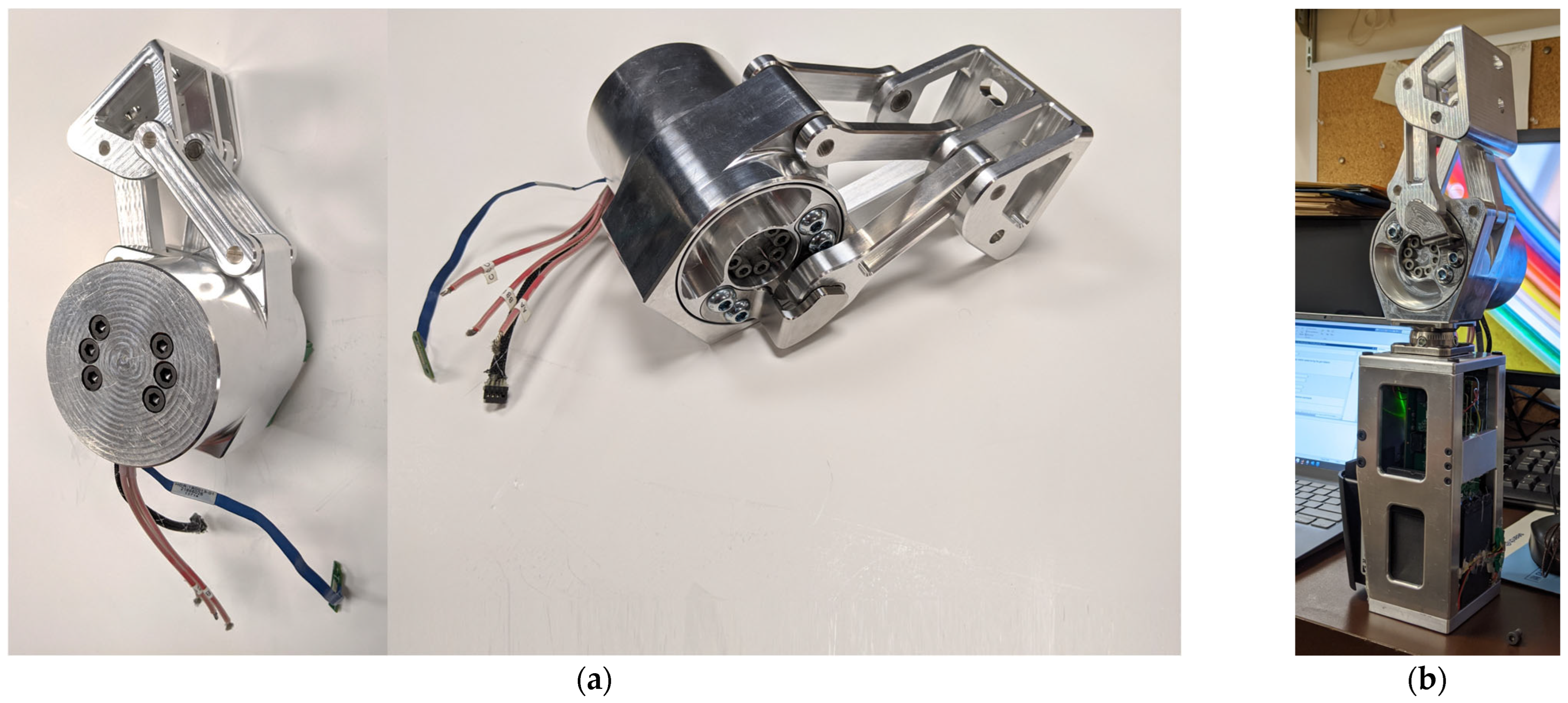
The first powered four-bar hip prototype (Figure 7a) contains machined powertrain components, an Össur actuator, and off-the-shelf components (needle bearings, shafts, class 10.9 screws, and washers). Aluminum 2024-T351 was selected for the motor housing and powertrain links due to its high strength-to-weight ratio. Shafts are prone to higher stress and greater wear; therefore, the shafts were manufactured from 17-4 PH SS H900 or M2 High Speed Steel (both materials are strong and wear resistant).
The four-bar hip joint powertrain (Figure 7a) has a mass of 2.676 kg. The powered four-bar hip, including the chassis (Figure 7b), has a mass of 4.337 kg, 1.137 kg above the 3.2 kg design requirement for device mass.

2.6. Structural Tests

ISO 15032:2000 is the only engineering standard for prosthetic hip joint structural testing [65]. The powered hip static compression test procedure was a simplification of the static failure test procedure outlined in ISO 15032:2000 and consisted of the following:
  • Install the prosthetic thigh in the uniaxial mechanical loading machine with appropriate lever arms,
  • Compress the hip to the 50 N stabilizing force,
  • Compress the hip joint to the 1024 N settling force and hold the force for 30 s before off-loading to the 50 N stabilizing force,
  • Compress the hip joint to the ductile failure ultimate test force of 3360 N and, when this peak force is reached, off-load the hip to the 50 N stabilizing force.
Loading and off-loading were at 200 N/s, within the loading rate range of 100 N/s to 250 N/s recommended by the standard [65].
A uniaxial mechanical test machine applied compression to the prosthetic thigh by keeping the lower attachment fixed and pushing downward on the upper attachment. Force and displacement were measured with sensors integrated into the test machine.
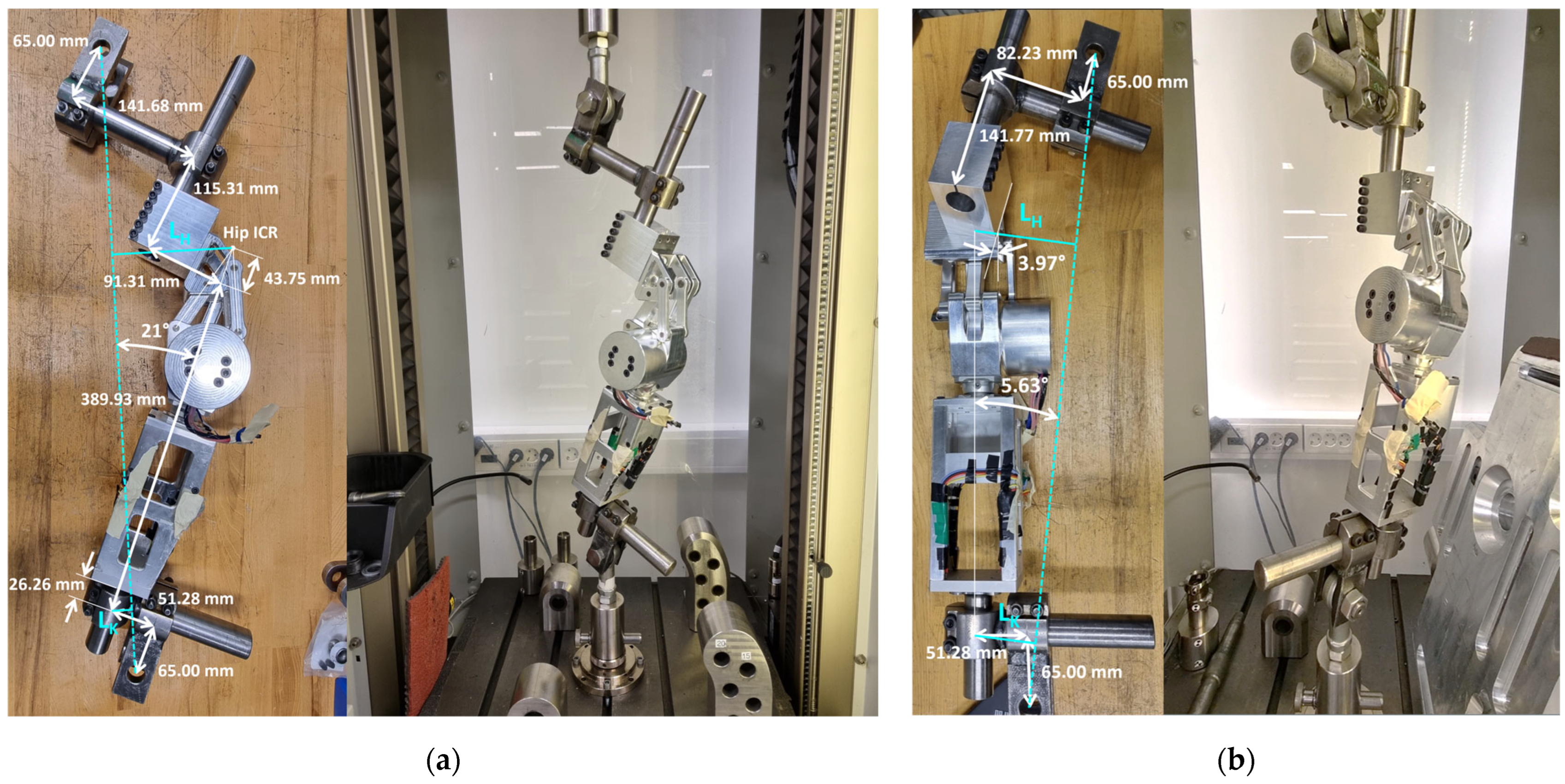
Two configurations were tested: the anterior-posterior (A-P) extension configuration with the hip fully extended and medial-lateral force alignment with the hip and knee (Figure 8a) and the medial-lateral (M-L) configuration with the hip fully extended but with a medial-lateral force offset relative to the hip and knee (Figure 8b). Appropriate hip and knee moment arms L H and L K were achieved with end attachments, each consisting of two perpendicular cylindrical poles. Due to the prosthetic thigh being longer than 400 mm, L H and L K were different than recommended in the standard but resulted in loading scenarios that were slightly more aggressive (i.e., passing these scenarios meant passing the scenarios outlined in the standard). The cylindrical poles were tightened at distances specified in Figure 8a,b. No battery was included in the chassis because no motor power was required for static compression testing.
The chassis, by itself, had previously passed separate static compression tests (chassis design and evaluation were carried out by Bader et al. [69]). The research presented in this paper covers the structural tests performed on the prosthetic thigh unit (the powered hip and chassis combined). Structural tests showed that the hip joint powertrain can support 100 kg at full extension without motor power.

2.7. Walking Tests

Structural tests showed that the powered hip could withstand typical loads from a 100 kg person. Walking tests determined if the powered hip could enable level walking, ideally for people weighing up to 100 kg.
Able-bodied participant testing with the prototype was approved by the University of Ottawa ethics board (H-08-21-7062). All participants signed an informed consent prior to testing. Walking tests were completed by able-bodied participants wearing an HKAFP simulator [70], placing the HKAFP lateral to the person’s right leg (Figure 9). The HKAFP simulator consisted of an Orthomerica Newport 3 hip abduction orthosis [71], powered four-bar hip, Rheo Knee XC3 [4], and Pro-Flex ST foot [72]. An adapter connected the HKAFP to the hip abduction orthosis, and straps held the body to the orthosis. A holster held a smartphone to collect pelvic motion data. A shoe with a thicker sole was worn on the sound side, and the HKAFP was configured to be slightly longer than the biological leg so that the biological leg on the prosthetic side was 4 cm above the ground. This setup allowed for an able-bodied person to walk like a hip-level amputee while achieving prosthetic side single-limb support. A cane was optionally used to aid with balance.
A convenient sample of three able-bodied male participants completed walking trials with the powered four-bar hip (Table 1). These participants represented the upper body weight limits that the prototype was designed to bear. In addition, their heights were appropriate for the length of the full-leg prosthesis used in the HKAFP simulator.

2.7.1. Control System

Prior to data collection, participants learned to walk with the HD prosthesis simulator with an early control system implemented into the powered hip. This control system provided high impedance to the motor so that the joint could move in a preconfigured trajectory while resisting external moments. The powered hip chassis was instrumented with load cells to detect foot-strike and foot-off instances, which allowed the control system to match the participant’s pace. At the start of walking, the control system flexed the hip to the maximum hip flexion angle preconfigured relative to each participant’s comfort. When the participant touched the ground with the prosthetic leg, the control system continually performed hip extension at a fixed speed until the maximum preconfigured hip extension was achieved. When the participant removed their body weight from the prosthesis at the end of extension, the control system flexed the hip to initiate swing phase. At the end of the swing phase, the hip returned to its fully flexed position in preparation for the next stride. During gait training, load cell sensitivities were adjusted to achieve toe-off timing and hip flexion-extension velocities that were comfortable for each participant.
Prosthetic shank control was achieved with the Össur Rheo Knee XC3 [4], a microprocessor knee with its own adaptive control system for real-time control. The Pro-Flex ST foot [72] is a purely mechanical energy-return foot.

2.7.2. Testing Protocol and Data Collection

Each participant completed one walking trial that consisted of walking back and forth on a 10-m walkway (i.e., walking 20 m in total). All three participants successfully completed at least 20 strides. Ten steady-state strides from each participant were selected for data analysis.
On average, each participant completed ten hours of gait training on the HKAFP prosthesis simulator before data collection with the powered four-bar hip. Two of the ten hours were spent learning to walk with the powered four-bar hip. The other eight hours were spent walking with other hip joints, including the 7E7, Helix3D, and two other powered hip joints developed by the research group (Brannen et al. [54], Mroz et al. [55]).
Pelvic motion was captured with the Data Logger smartphone application (developed by The Ottawa Hospital Rehabilitation Centre), with a smartphone attached to the posterior of the pelvis. The data logger sampled accelerometer, gyroscope, and magnetometer sensors at 60 Hz. For each walking trial, the powered hip angle sensor measured hip motor angle and the Össur Rheo Knee angle sensor measured knee flexion-extension angle. Össur’s custom data logger hardware and software recorded the data collected from both angle sensors. Through mapping, hip motor angle data were converted to hip flexion-extension data. Each walking trial was captured on smartphone video, using a separate phone. The video clips were imported into the Kinovea software (version 0.9.5) [73] to extract spatiotemporal parameters.

3. Results

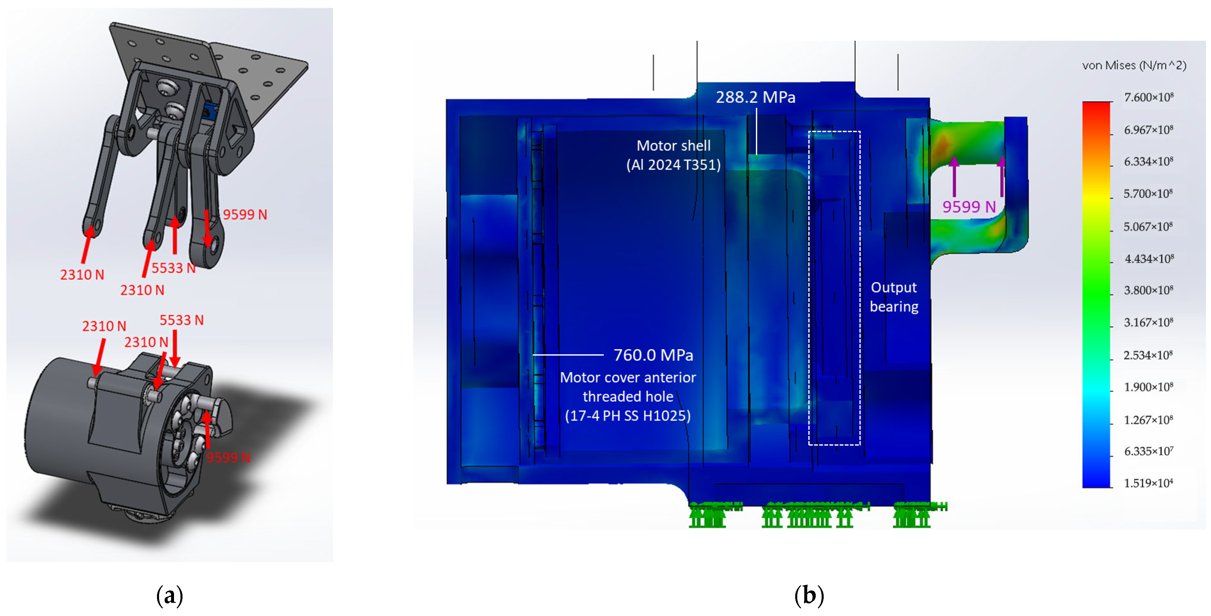
Force analysis showed that maximum actuator torque alone (96 N-m) at full hip extension resulted in the largest link forces [74]. Figure 10a presents link forces acting in this scenario. Finite element analysis was performed by applying forces to the upper and lower units separately while keeping the posterior surface of the superior link and the inferior surface of the motor housing fixed. Figure 10b shows a von Mises stress color map, in the largest force scenario, on a medial-lateral cross-section cut through the middle of the lower unit. Von Mises stresses on the lower unit were larger than on the upper unit.
Posterior link force was 5533 N, anterior link force was 2310 N, and drive arm force was 9599 N. Under these forces, the maximum von Mises stress on an Aluminum 2024-T351 component was 280 MPa on the motor shell, well below the 310 MPa yield strength of Aluminum 2024-T351 [75]. The maximum von Mises stress on a stainless-steel component was 760 MPa on the motor cover, well below the 1000 MPa yield strength of 17-4 PH SS H1025 [76]. These results showed that the device will not yield when the motor operates at maximum torque.
Fatigue analysis on powertrain structural components showed that the structure most susceptible to fatigue was the motor shell at 364,863 load cycles [74]. However, bearing analysis revealed that the fatigue life of the hip joint powertrain was governed by the output bearing at 82,382 load cycles (i.e., 82,382 steps with the HKAFP) [74]. A fatigue life of 2 million load cycles corresponds to two to three years of prosthetic hip joint use by an HD/HP amputee (approximately 3650–5500 steps walked per day) [34,77,78,79,80]. The powered four-bar hip’s 82,382-cycle fatigue life therefore correlates to approximately 30–45 days of continued use by an HD/HP amputee. Participants took approximately 50 steps per walking trial, projecting a fatigue life of about 1647 walking trials before any damage occurs, which was sufficient at this stage.
ISO 15032:2000 static compression force-displacement profiles for A-P extension compression (Figure 11a) and M-L compression (Figure 11b) display the rising portion of compressive force from the 50 N stabilizing force to the 3360 N ultimate test force.
The prosthetic thigh is mainly composed of Al 2024 T351 and 17-4 PH SS H900, both of which are linear elastic and ductile materials. Figure 11a,b show that the compressive force-displacement profiles remained approximately linear for both A-P extension and M-L tests. Both force-displacement profiles did not contain a sharply decreasing rate of change that would correspond to a stress-strain curve beyond the yield point. After each test, the prosthetic thigh was thoroughly inspected for distorted geometry, newly formed gaps, and cracks, but none were found. These observations demonstrated that the prosthetic thigh did not yield during static compression testing, thereby satisfying the ISO 15032:2000 strength requirements for supporting a 100 kg user.
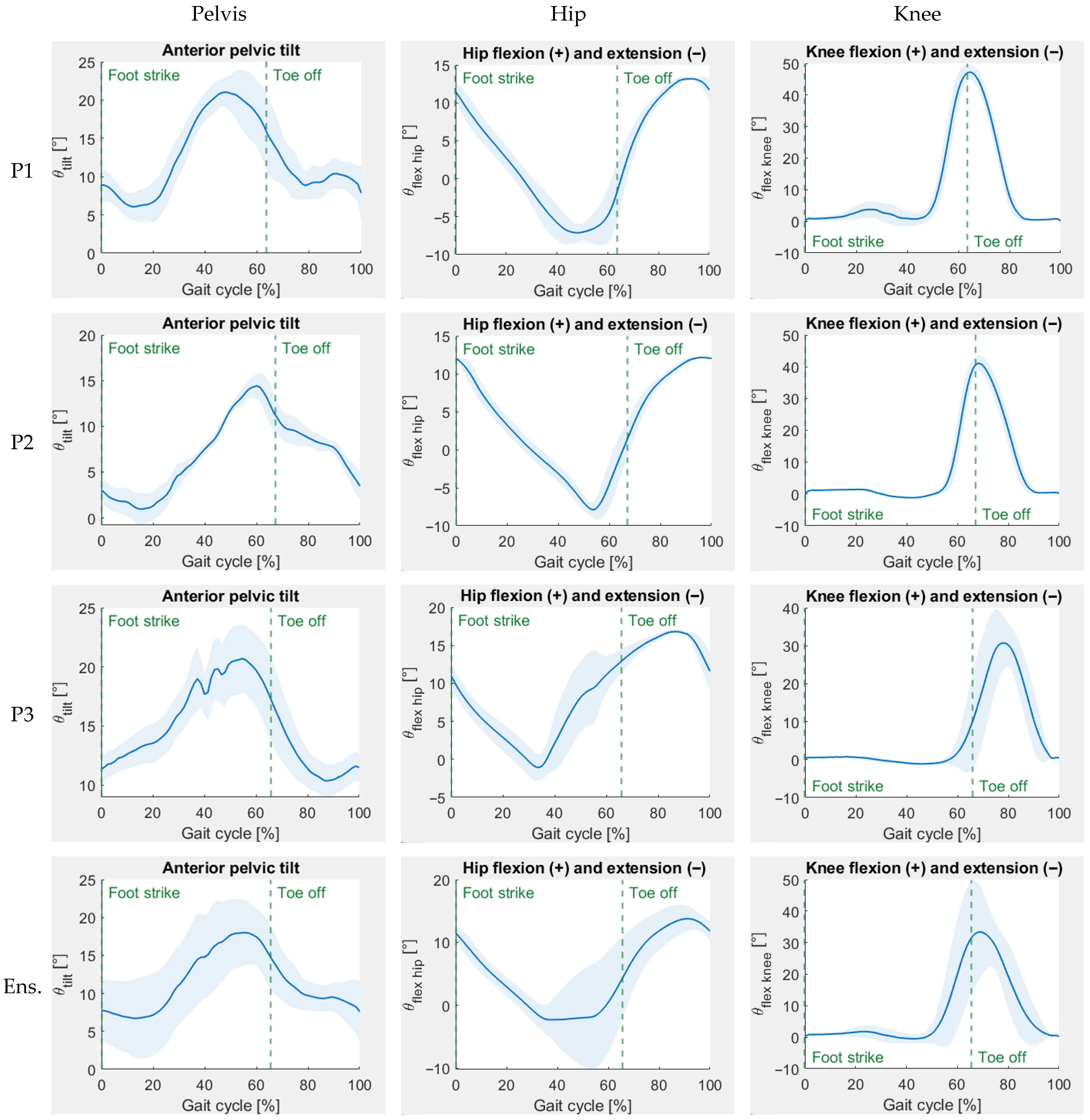
Figure 12 shows prosthetic side kinematic results for the straight-line walking. Prosthetic lower limb ranges of motion and extreme values are listed in Table 2, and spatiotemporal results are listed in Table 3. All results are presented for each participant and the ensemble.
The shapes of the HKAFP kinematic gait profiles (Figure 9) resembled those seen in transfemoral amputee gait [27,56,57,59,60,62,63]. At the beginning and end of each stride, anterior pelvic tilt was at its minimum, the hip was fully flexed, and the knee was fully extended. In between late stance and early swing, anterior pelvic tilt was at its maximum, the hip was fully extended, and the knee was fully flexed. This transfemoral-like gait pattern was visually observed during participant walking trials (Figure 13), indicating that successful walking can be achieved with the powered four-bar hip.
Higher levels of gait performance are indicated by maintaining constant spatiotemporal parameters and joint angles between steps and being symmetric or almost symmetric between sound and prosthetic limbs. Of the three participants, participant 2 had the best gait performance due to the smallest standard deviations in support times, cadence, and step length, and the smallest difference between sound and prosthetic side single-limb support times and step lengths. Furthermore, participant 2 had the lowest standard deviation for prosthetic side joint angle profiles (Figure 9) (i.e., consistent gait between steps) and the fastest average walking speed (tied with participant 1).
Participant gait asymmetries included a shorter average prosthetic step length than average intact limb step length and a shorter average prosthetic side single-support time than average sound side single-support time. The average early-stance double-support time was slightly greater than the average late-stance double-support time. The average sound leg step length was slightly greater than the average prosthetic leg step length, showing some degree of spatial step symmetry, despite the lack of temporal step symmetry.
On average, participants walked at 0.45 m/s, approximately one-third the normal walking speed of 1.39 m/s [81]. Participants were observed to be more comfortable walking with smaller steps (0.4 m on average, 56% the length of a normal 0.72 m step [81]). In addition, the average 69 steps/min cadence was slower than the normal 100 steps/min cadence for moderate-intensity walking [82].
After level-ground walking trials were completed, the powered hip was inspected for signs of mechanical failure (i.e., cracks and geometric distortion). None were found; hence, the powered hip successfully supported a 98 kg person (the heaviest participant) during level-ground walking.

4. Discussion

This research described and evaluated a novel four-bar powered hip joint that enabled safe walking, in addition to being structurally viable. In relation to other research, the powered four-bar hip was a complete unit with battery and electronics that would fit under clothing, in comparison to the prototype by Ueyama et al. [12]. The four-bar linkage provided greater foot clearance than the single-axis powered hips developed by others in our research group [54,55].
Force and finite element analyses showed that the device will not yield if the motor were to operate at its full 96 N-m torque. The prototype contained 17-4 PH SS H900 as opposed to the 17-4 PH SS H1025 used in finite element analysis. The H900 variant was more easily obtainable and resulted in a higher yield strength with some sacrifice in ductility and fatigue life. The loss in fatigue life did not affect design performance because the output bearing would fail in fatigue far earlier than both Aluminum 2024-T351 and 17-4 PH SS H1025. Future prototypes could contain a supplementary bearing within the drive flange to offload or replace the output bearing and better balance fatigue loading throughout the device, increasing overall fatigue life.
ISO 15032:2000 static compression tests verified structural strength for a 100 kg body weight. While some populations are heavier [83], the 100 kg target is the maximum test weight in ISO 15032:2000. As the powered hip design process continues, different versions for heavier users could be considered.
Despite both the A-P and M-L compression tests being in the elastic stress-strain region, greater vertical displacement and non-linearity were observed during the M-L test because there was slight frontal plane rotation between the upper attachment and the superior link, and between the powered hip and chassis. This rotation occurred due to insufficient friction between components for them to be held perfectly still during the tests. This extra displacement in the M-L test did not greatly affect hip and knee moment arms, and thus, the M-L test results were still valid for interpretation.
Walking tests demonstrated that an appropriate gait pattern is possible with the four-bar hip and that the device is robust when subjected to both body weight and motor torque simultaneously. Able-bodied people, with limited experience walking with an HKAFP, were able to consistently achieve steady walking trials without stumbling or damaging the device.
The powered four-bar hip control system allowed participants to walk with a typical cyclic gait pattern, which was sufficient to demonstrate that the mechanical design is appropriate for walking. While successful walking was achieved, gait asymmetry and slower walking speeds were observed. Future research will incorporate a more robust control system that accommodates starting/stopping and variations in walking speed and terrain. A more advanced control system and greater confidence in a participant’s ability to walk with the prosthesis could help improve walking speed. Since this paper focused on mechanical design, a full control system was not required at this stage of development.
Smaller step lengths corresponded to smaller changes in joint angles during each stride. The ensemble hip ROM was 20.65 ± 0.69°, and the ensemble knee ROM was 42.10 ± 6.88°. These joint ROM values were smaller than those reported in the literature for able-bodied people, transfemoral amputees, and HD/HP amputees [9,26,27,28,41,56,57,58,59,60,61,62,63,84,85].
Participant 2 showed the least variation in their hip and knee flexion profiles (Figure 9). Standard deviation regions showed that all participants had some variation on the timing of stance phase hip flexion, with participant 2 having the least variation. These variations were caused by inconsistencies in sound versus prosthetic single-support times. The gait cycles of participants 1 and 3 terminated considerably past the peak in the hip flexion curve, indicating that the prosthesis swung further than necessary to achieve a comfortable stride. This excessive prosthetic swing was not prevalent for participant 2. Pre-swing knee flexion timing was consistent for participants 1 and 2, but not for participant 3.
Participants showed increased anterior pelvic tilt relative to able-bodied people [28,84,85]. The ensemble range of anterior pelvic tilt was 14.48 ± 3.13°. Participant 2 experienced the least variation in their pelvic ROM. Participants 1 and 3 walked in a more leaned forward manner than participant 2.
Anterior pelvic tilt was a gait compensation mechanism to increase lower limb ROM during early stance. The preliminary control system may have set the hip extension resistance to be higher than what it should have been for ideal gait performance. Hip extension resistance was increased to give each participant a greater sense of stability during mid-to-late stance. However, the HKAFP was not rotating backward as far as it could have during late stance. Therefore, participants may have tilted their pelvis forward (with the 19.65 ± 4.07° peak occurring during late stance) to continue backward motion of the prosthetic leg. Appropriate hip extension resistance during stance (e.g., a control system that provides both high and low joint resistance) would likely reduce the anterior pelvic tilt magnitude because more of the prosthetic leg’s backward motion would be coming from the powered hip.
Kinematic and spatiotemporal results showed that participant 2 was able to best adapt to the control system and develop a steady gait. This observation shows the need for a more adaptive control system to accommodate different load-bearing habits. Of note, this study was to evaluate the mechanical aspect of the power hip, not to develop the final control system.
These results came from participants who completed only ten hours of walking sessions with the HKAFP simulator, with sporadic bouts of walking within the sessions. With more gait training, the participants could have exhibited gait closer to normal gait patterns. Different people require different lengths and types of gait training to achieve a certain gait performance level.
Transfemoral amputee gait is distinct from HD amputee gait with a passive hip because transfemoral amputees have a more controlled and steady hip extension during the stance phase than HD amputees [9,26,27,56,57,59,60,62,63]. Participants 1 and 2 had prosthetic hip extension at an approximately constant angular velocity until full extension occurred at 50–55% of the gait cycle. This hip extension pattern resembled transfemoral amputee behavior [27,56,57,59,60,62,63]. Participant 3 was the least comfortable with the HKAFP simulator and therefore, was not as controlled in their hip extension, with full extension occurring at about 35% of the gait cycle. None of the participants had an HD amputee-like hip extension curve, one that reaches full or near-full extension in the early stance phase (i.e., 10–15% gait cycle) and then plateaus for the remainder of the stance phase [9,26]. These results showed that the powered hip’s actuator provides a means of slowing down hip extension during weight bearing, thereby being more effective than passive damping elements.
Able-bodied walking with the HD prosthesis simulator provided a good indication of mechanical performance during walking but should differ from HD amputee gait. When a person uses the HD prosthesis simulator, their prosthetic leg is further away from the body’s natural COM location than their sound leg. Consequently, the moment arm between the prosthetic leg and the COM is larger in able-bodied walking than in HD amputee walking. This increased moment arm causes a medial-lateral asymmetry between prosthetic and sound legs that increases the difficulty of maintaining medial-lateral balance during prosthetic side single-limb support.
When transitioning from able-bodied to HD/HP amputee testing, powered hip performance is anticipated to improve because the amputee will wear a socket to which the device is directly attached in the appropriate alignment for standing and prosthetic leg propulsion. Furthermore, this prosthetic leg placement on the amputee would also place sensors directly on the pelvis. As a result, the amputee will walk with more steady control and medial-lateral symmetry.
The powered hip addressed most of the design requirements:
  • The powered hip was required to provide up to 20° extension and 130° flexion. The prototype met the extension criterion but was 30° short of meeting the flexion criterion. As an early prototype, 100° flexion would permit sitting, but further refinement could increase the flexion range.
  • The powered hip met the 100 kg user criterion by passing the mechanical tests and successfully supporting walking for the 98 kg participant.
  • The powered hip and chassis combined weight exceeded the 3.2 kg device criterion, with the prototype weighing 4.337 kg. However, participants mentioned that the powered hip did not feel heavy during walking due to the hip flexion-extension assistance the actuator provided. Although a lighter prosthetic mass would be ideal, the extra prototype mass did not greatly affect gait due to the powerful actuator implemented in the four-bar hip.
  • The Össur Power Knee 2 DC motor provides a torque of up to 96 N-m, an angular velocity of up to 300°/s, and a power of up to 503 W, easily meeting the actuator criteria.
  • The powered hip, from the posterosuperior pin and below but not including the chassis, needed to have a length, width, and height of less than 17 cm in neutral position. The respective powered hip neutral position dimensions are 11.61 cm, 13.48 cm, and 15.51 cm, which meet the size criteria.
  • Cosmetic criteria were mostly met. The powered hip is anteriorly mounted, within the acceptable thigh dimensions, and does not protrude from the bottom in the sitting position. The slight anterior bulge of the powered hip can be reduced in future prototypes.
  • During mid-swing, the powered hip was required to shorten to enhance toe clearance and reduce tripping risk. The powered hip shortens by 23.8 mm.
Prosthetic hip flexion was limited at 100° by contact between the motor housing and socket. Hip flexion range could be increased by modifying powertrain geometry. For example, socket contact would occur at greater hip flexion if anterior and posterior link lengths were increased and superior and inferior link lengths kept the same. The challenge is making this modification while maintaining design performance.
Future prototype mass could be reduced by redesigning electronic components to take up less volume, resulting in a smaller chassis. Reducing chassis length would result in a shorter prosthetic thigh that better accommodates end users of shorter heights. Replacing the current actuator with a new Össur motor that is smaller and lighter but still has a sufficient torque output would also reduce device mass. Powered hip materials could also be reassessed for lighter alternatives.
Future walking tests should measure additional quantities such as sound leg kinematics and both prosthetic and sound leg kinetics (hip motor torque and lower limb forces). The additional measurements would better assess gait symmetry and structural integrity during gait.
The powered hip was mechanically optimized to provide the largest mechanical advantages within the walking ROM (20° extension and 40° flexion). However, due to a reduced moment arm between the drive arm and hip ICR at high hip flexion, mechanical advantage at high hip flexion was reduced, thereby reducing maximum torque output at high hip flexion. For this reason, the powered hip would not perform as well in high hip flexion activities. In ramp ascent, the affected stance subphases would be loading response and terminal stance since the motor would need to prevent prosthetic buckling, and the affected swing subphases would be mid-swing and terminal swing since the motor would need to maintain appropriate forward velocity. Future powered hip designs could place the mechanical advantage peak further into hip flexion to better assist ramp ascent and provide balance assistance in other high hip flexion activities. The control system would ensure an increase in motor power where mechanical advantage is low.
Future evaluation of powered hip performance should be completed with hip-level amputees. Hip-level amputee gait data would better represent powered hip performance than gait data from able-bodied participants using an HKAFP simulator and would inform further improvements to the powered four-bar hip prototype.

5. Conclusions

A powered four-bar hip joint was developed to assist people with HD or HP amputations. The powered hip passed static compression testing adapted from the ISO 15032:2000 standard and successfully enabled level-ground walking with an HKAFP simulator. Areas for powered hip improvement are ROM, device mass, and mechanical advantage at high hip flexion. Device geometry modifications could improve hip ROM and mechanical advantage at high hip flexion angles. Device mass could be reduced by redesigning the chassis to be smaller and using the newest Össur Power Knee motor that is smaller and lighter. Since people successfully walked with the powered hip, this research demonstrated that the powered four-bar hip is safe for use and viable for further testing with HD and HP amputees.

Author Contributions

Conceptualization, M.B., E.D.L., N.B., F.G., D.L. and H.G.; methodology, M.B., E.D.L. and N.B.; software, M.B. and F.G.; validation, M.B.; formal analysis, M.B.; investigation, M.B.; resources, E.D.L., N.B. and D.L.; data curation, M.B.; writing—original draft preparation, M.B.; writing—review and editing, M.B., E.D.L. and N.B.; visualization, M.B.; supervision, E.D.L., N.B. and D.L.; project administration, E.D.L. and N.B.; funding acquisition, E.D.L. and N.B. All authors have read and agreed to the published version of the manuscript.

Funding

This research was funded by Mitacs (grant number IT17303), NSERC Create-READi, and Össur.

Institutional Review Board Statement

The study was conducted in accordance with the Declaration of Helsinki and approved by the Research Ethics Board of the University of Ottawa (protocol code: H-08-21-7062 and date of approval: 18 October 2021).

Informed Consent Statement

All study participants gave informed consent.

Data Availability Statement

Data sharing is not applicable to this article.

Acknowledgments

The authors would like to thank The Ottawa Hospital Rehabilitation Centre, the University of Ottawa, and Össur for providing resources for development and testing.

Conflicts of Interest

Author David Langlois was employed by the company Össur. The remaining authors declare that the research was conducted in the absence of any commercial or financial relationship that could be construed as a potential conflict of interest.

Appendix A

Appendix A.1. Equations for Step 1 of Each Iteration to Optimize Powertrain Linkages
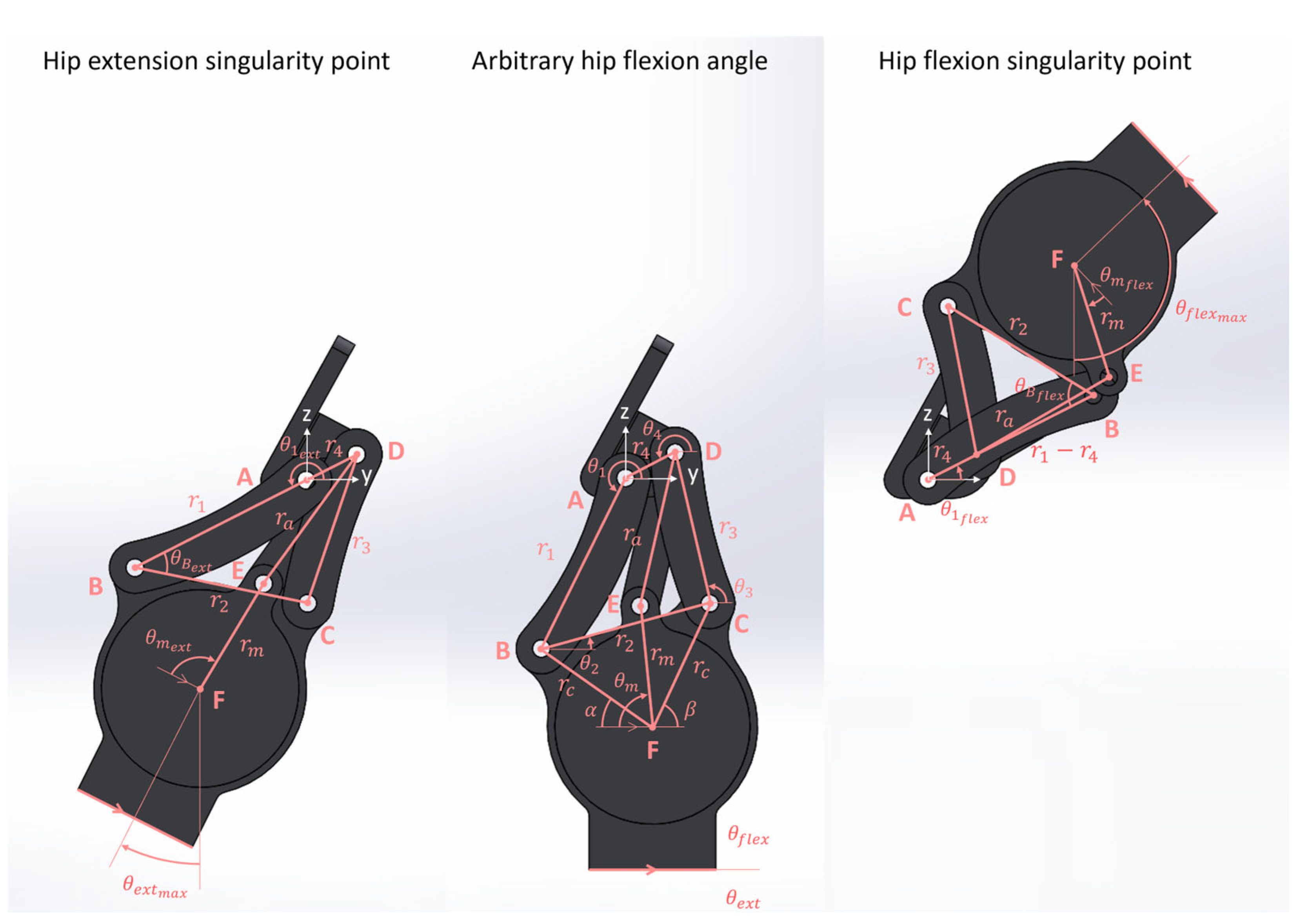
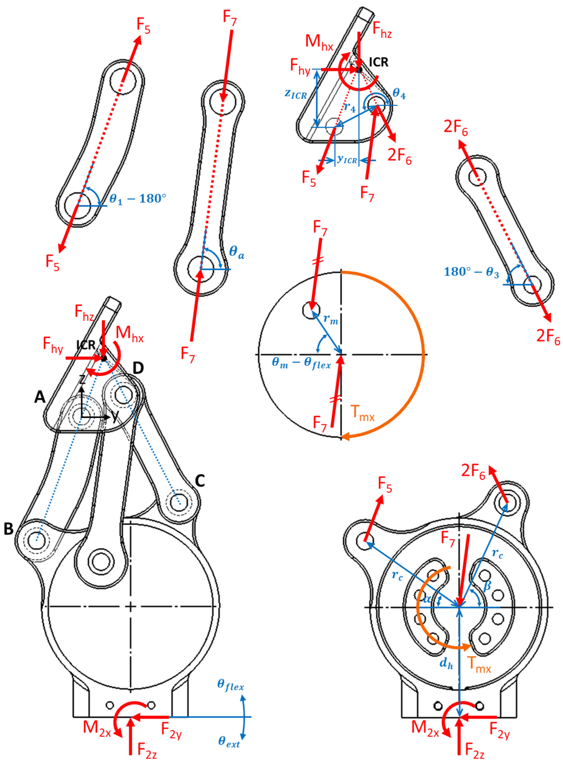
Figure A1 illustrates the dimensions that define powertrain linkages at the extremities of hip ROM (i.e., singularity points) and at an arbitrary hip flexion angle. Singularity points occur when the posterior (AB) and superior (AD) links are collinear, and therefore, the powered hip cannot flex or extend any further.
Figure A1. Powered hip sagittal plane dimensions at arbitrary and singularity hip flexion-extension positions. Positive y is anterior and positive z is superior. Earlier powered hip model shown.
Prosthesis 07 00105 g0a1
Dimensions r c , r 4 , α , β, θ 4 , θ e x t m a x , θ f l e x m a x , θ m e x t , and θ m f l e x were the design variables. Values for these dimensions were selected as inputs for step 1 of each linkage optimization iteration. Difference θ f l e x m a x θ e x t m a x represents overall hip ROM. Difference θ m e x t θ m f l e x represents actuator ROM. During step 1, dimensions r 1 , r 3 , r a , and r m (output linkage dimensions) were calculated using the following trigonometric relationships (all variables defined in Figure A1):
r 1 = r 2 r 4 cos θ B f l e x + cos θ B e x t 2 r 4 + r 2 cos θ B f l e x cos θ B e x t   ,
where
r 2 = 2 r c 2 1 cos 180 ° α β ,
θ B f l e x = θ 4 θ f l e x m a x 1 2 β α ,
and
θ B e x t = θ 4 + θ e x t m a x 1 2 β α 180 ° .
Next,
r 3 = r 1 r 4 2 + r 2 2 2 r 1 r 4 r 2 cos θ B f l e x .
Also,
r m = r D F f l e x 2 r D F e x t 2 2 r D F f l e x cos θ F f l e x θ m f l e x + α r D F e x t cos θ F e x t θ m e x t + α   ,
where
r D F f l e x = r 1 r 4 2 + r c 2 2 r c r 1 r 4 cos θ B f l e x + α + β 2 ,
r D F e x t = r 1 + r 4 2 + r c 2 2 r c r 1 + r 4 cos θ B e x t + α + β 2 ,
θ F f l e x = sin 1 r 1 r 4 sin θ B f l e x + α + β 2 r D F f l e x ,
and
θ F e x t = sin 1 r 1 + r 4 sin θ B e x t + α + β 2 r D F e x t .
Furthermore,
r a = r m 2 + r D F f l e x 2 2 r m r D F e x t cos θ F f l e x θ m f l e x + α .
Figure A2 presents powertrain protrusion dimensions in the standing and sitting positions. These dimensions quantified how well the hip joint satisfied cosmesis and comfort requirements.
Figure A2. Powered hip sagittal plane protrusion dimensions in the standing and sitting positions. Positive y is anterior and positive z is superior. Earlier powered hip model shown.
Prosthesis 07 00105 g0a2
Dimension l defined the anterior protrusion of the hip joint in the standing position and was calculated by the following equations:
l = m a x ( l 1 , l 2 ) ,
l 1 = r 1 cos θ 1 s t a n d + r 2 cos 1 2 β α + r c u r v e y p l a t e ,
and
l 2 = r 1 cos θ 1 s t a n d + r c cos α + r m o t o r + t h y p l a t e .
Dimension h defined the superior protrusion of the hip joint in the sitting position and was calculated by the following equations:
h = m a x ( h 1 , h 2 ) ,
h 1 = r 1 sin θ 1 s i t + r 2 sin 1 2 β α + r c u r v e z b o t t o m ,
and
h 2 = r 1 sin θ 1 s i t + r c cos α + r m o t o r + t h z b o t t o m .
Dimension Δ z defined the inferior protrusion of the hip joint in the sitting position and was determined as follows:
z = r 1 sin θ 1 s i t r c u r v e z b o t t o m
All parameters required for Equations (A12)–(A18) are defined in Figure A2. The equations used to determine θ 1 s t a n d and θ 1 s i t (posterior link angles in the standing and sitting positions) are presented in the thesis entitled “Design and Evaluation of a Powered Four-Bar Prosthetic Hip Joint” [74].
Table A1 lists input and output constraints for step 1 of a hypothetical iteration that satisfies all design requirements simultaneously. Step 1 consisted of making guesses for appropriate r c , r 4 , α , β , and θ 4 values, choosing angle boundary values for hip and motor ranges of motion that satisfy the input constraints, calculating the output dimensions with Equations (A1)–(A18), and then checking if the calculated output values fall within the output constraints.
Table A1. Geometric constraints for an ideal linkage optimization iteration.
Inputs (°) 1Outputs (cm)
θ e x t m a x θ f l e x m a x θ m e x t θ m f l e x r 1 r 3 r a r m l h z
>21.0>131.0>152.0<9.30<9.30<9.30>2.15 and <3.37<2.00<17.00≥0.00
1  r c , r 4 , α , β , and θ 4 were set to any value so long as input and output constraints were satisfied.
Nearly 200 iterations revealed that compromises needed to be made to ensure design robustness and adequate mechanical advantage without mechanical interference [74]. As a result, the iteration presented in Table A2 was selected. This iteration resulted in the hip joint providing steady walking for a 98 kg user, despite not meeting ROM and cosmesis requirements.
Table A2. Step 1 parameters of linkage optimization iteration chosen for powered four-bar hip joint.
Inputs (°) 1Outputs (cm)
θ e x t m a x θ f l e x m a x θ m e x t θ m f l e x r 1 r 3 r a r m l h z
36.5109.589.1−39.06.12247.08548.22853.27396.066711.52401.9915
1 Additional inputs were r c = 5.35 cm , r 4 = 3.30 cm , α = 35.0 ° , β = 65.0 ° , and θ 4 = 207.0 ° .

Appendix A.2. Equations for Step 2 of Each Iteration to Optimize Powertrain Linkages
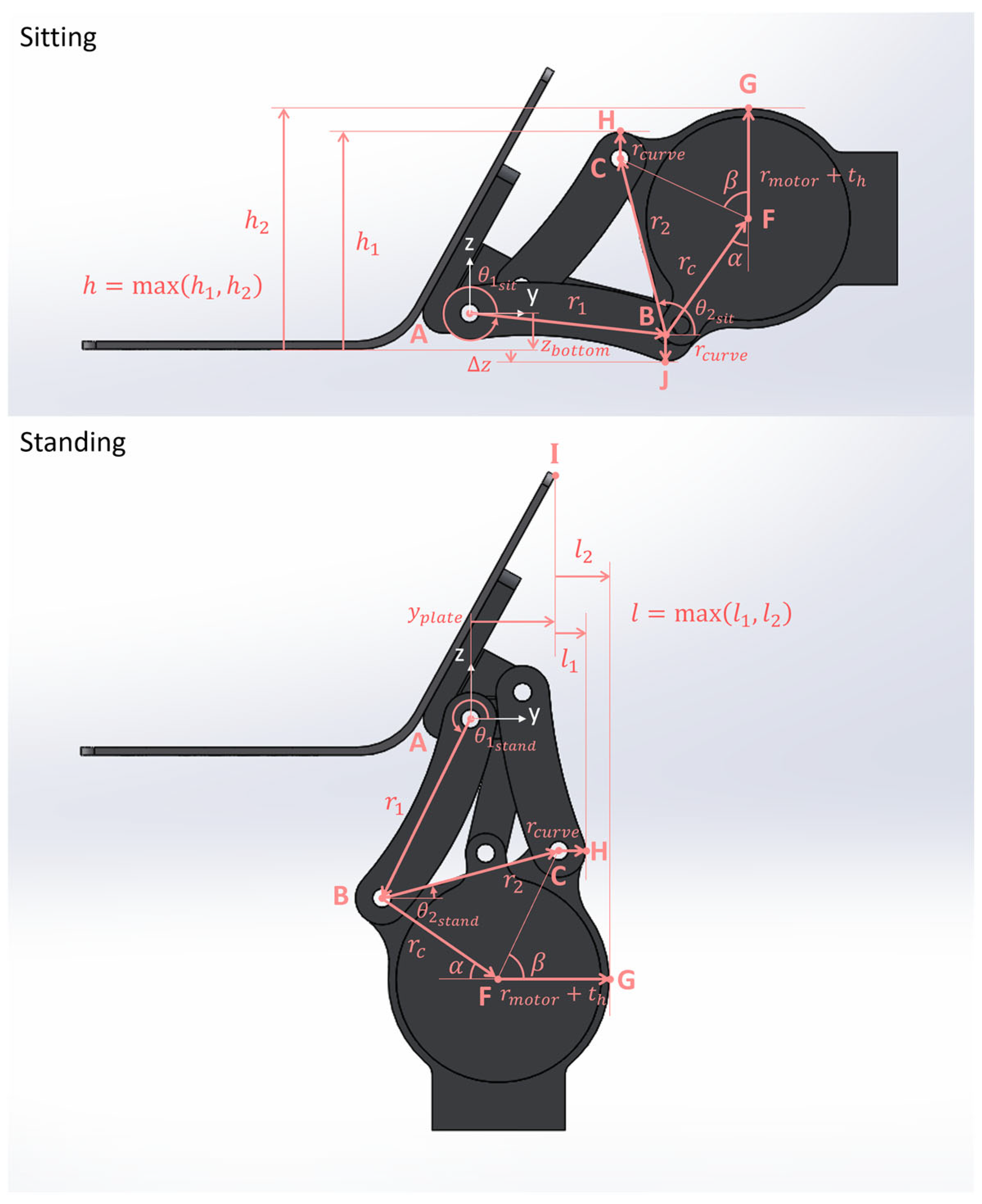
Figure A3 shows the powered hip at an arbitrary hip flexion angle and dismembers the powered hip into individual free bodies.
Figure A3. Powered hip free body diagrams at an instance of the gait cycle. Earlier powered hip model shown at an arbitrary hip flexion angle.
Prosthesis 07 00105 g0a3
For simplification, the following assumptions were made during the force analysis performed in step 2 of each linkage optimization iteration:
  • Starting from full extension, the hip moved through its ROM to full flexion, while maintaining static equilibrium.
  • There was no pelvic tilt, pelvic obliquity, or pelvic rotation at any instance within hip ROM.
  • Forces acted in the sagittal plane only.
  • Motor torque T m x was constant at its maximum 96 N-m (torque direction did not affect force and moment magnitudes (only their signs) so long as free body diagram conventions were respected).
  • All motor torque was transmitted through the drive arm with force F 7 .
  • Body weight was not acting on the joint. Force analysis showed that the single 96 N-m torque at full hip extension was a greater load than the greatest combined body weight and motor torque expected during walking [74].
  • Individual component weights and inertial loads were neglected because they were much smaller compared to body weight and motor torque.
Applying the sum of moments on the motor in static equilibrium gave an expression for drive arm force F 7 :
F 7 = T m x r m cos θ a sin θ m θ f l e x + sin θ a cos θ m θ f l e x .
Taking the sum of moments on the superior link in static equilibrium at the hip ICR gave an expression for hip moment M h x :
M h x = F 7 cos θ a z I C R r 4 sin θ 4 180 ° + sin θ a r 4 cos θ 4 180 ° y I C R .
Mechanical advantage (MA) for the powered hip was defined as the ratio of output load to input load:
M A = M h x T m x .
Combining Equations (A19)–(A21) gave an expression for mechanical advantage in terms of known link lengths, link angles, and joint angles:
M A = cos θ a z I C R r 4 sin θ 4 180 ° + sin θ a r 4 cos θ 4 180 ° y I C R r m cos θ a sin θ m θ f l e x + sin θ a cos θ m θ f l e x .
All parameters used in Equations (A19)–(A22) are defined in Figure A3. The equations used to determine drive arm angle θ a and motor angle θ m , and the hip ICR coordinates ( y I C R , z I C R ) are presented in the thesis entitled “Design and Evaluation of a Powered Four-Bar Prosthetic Hip Joint” [74].
Step 2 of a linkage optimization iteration, a continuation of step 1, consisted of applying Equations (A19) and (A22) to 51 equally spaced instances from full hip extension to full hip flexion (i.e., plugging in 51 distinct θ f l e x values), and checking the drive arm force and MA values against their respective thresholds. For motor component integrity, the drive arm force could not exceed 10077 N. For optimal walking assistance, MA needed to be greater than 1 within walking ROM (20° hip extension to 40° hip flexion). The linkage optimization iteration chosen for the powered four-bar hip resulted in a 9599 N maximum drive arm force and MA values above 1 within walking ROM (with the peak MA being 1.64 at 10° hip flexion). Thus, both structural and performance metrics were met.

References

  1. Fite, K.B. Overview of the Components Used in Active and Passive Lower-Limb Prosthetic Devices. In Full Stride: Advancing the State of the Art in Lower Extremity Gait Systems; Tepe, V., Peterson, C.M., Eds.; Springer: New York, NY, USA, 2017; pp. 55–74. ISBN 978-1-4939-7247-0. [Google Scholar]
  2. Helix3D Hip Joint, Right | Hips | Lower Limb Prosthetics | Prosthetics | Ottobock CA Shop. Available online: https://shop.ottobock.ca/en/Prosthetics/Lower-Limb-Prosthetics/Hips/Helix3D-Hip-Joint%2C-right/p/7E10~5R#product-specification-section (accessed on 7 December 2022).
  3. C-Leg 4. Available online: https://www.ottobock.com/en-us/product/3C88-3~23C98-3 (accessed on 7 December 2022).
  4. Rheo Knee®. Available online: https://www.ossur.com/en-ca/prosthetics/knees/rheo-knee (accessed on 7 December 2022).
  5. Power KneeTM. Available online: https://www.ossur.com/en-ca/prosthetics/knees/power-knee (accessed on 7 December 2022).
  6. INTUY® Knee: Motorized, Lightweight, Intuitive, Safe. Available online: https://www.rbionics.com/products/prosthetic-knee/ (accessed on 2 June 2025).
  7. Product | BionicM. Available online: https://bionicm.com/product (accessed on 2 June 2025).
  8. Empower. Available online: https://shop.ottobock.us/Prosthetics/Lower-Limb-Prosthetics/Feet---Microprocessor/Empower/p/1A1-2#product-documents-section (accessed on 7 December 2022).
  9. Ludwigs, E.; Bellmann, M.; Schmalz, T.; Blumentritt, S. Biomechanical Differences Between Two Exoprosthetic Hip Joint Systems during Level Walking. Prosthet. Orthot. Int. 2010, 34, 449–460. [Google Scholar] [CrossRef]
  10. Kawaguchi, T.; Yamada, T.; Iwashita, K. Biomechanical Gait Analysis for a Hip Disarticulation Prosthesis: Power Source for the Swing Phase of a Hip Disarticulation Prosthetic Limb. J. Phys. Ther. Sci. 2023, 35, 361–365. [Google Scholar] [CrossRef]
  11. Gholizadeh, H.; Baddour, N.; Botros, M.; Brannen, K.; Golshan, F.; Lemaire, E.D. Hip Disarticulation and Hemipelvectomy Prostheses: A Review of the Literature. Prosthet. Orthot. Int. 2021, 45, 434–439. [Google Scholar] [CrossRef]
  12. Ueyama, Y.; Kubo, T.; Shibata, M. Robotic Hip-Disarticulation Prosthesis: Evaluation of Prosthetic Gaits in a Non-Amputee Individual. Adv. Robot. 2020, 34, 37–44. [Google Scholar] [CrossRef]
  13. Bowker, H.; Michael, J. (Eds.) Atlas of Limb Prosthetics: Surgical, Prosthetic, and Rehabilitation Principles, 2nd ed.; American Academy of Orthopedic Surgeons: Rosemont, IL, USA, 1992. [Google Scholar]
  14. Chin, T.; Sawamura, S.; Shiba, R.; Oyabu, H.; Nagakura, Y.; Nakagawa, A. Energy Expenditure During Walking in Amputees after Disarticulation of the Hip: A Microprocessor-Controlled Swing-Phase Control Knee Versus a Mechanical-Controlled Stance-Phase Control Knee. J. Bone Jt. Surgery. Br. Vol. 2005, 87, 117–119. [Google Scholar] [CrossRef]
  15. Chin, T.; Oyabu, H.; Maeda, Y.; Takase, I.; Machida, K. Energy Consumption During Prosthetic Walking and Wheelchair Locomotion by Elderly Hip Disarticulation Amputees. Am. J. Phys. Med. Rehabil. 2009, 88, 399–403. [Google Scholar] [CrossRef] [PubMed]
  16. Jeans, K.A.; Browne, R.H.; Karol, L.A. Effect of Amputation Level on Energy Expenditure During Overground Walking by Children with an Amputation. J. Bone Jt. Surg. Am. Vol. 2011, 93, 49–56. [Google Scholar] [CrossRef]
  17. Langlois, D. Powered Hip Joint Unexplored Clinical Opportunities of Powered Prosthetics 2015. In Proceedings of 2015 AOPA National Assembly Clinical Education Program, San Antonio, TX, USA, 7–10 October 2015. [Google Scholar]
  18. Nowroozi, F.; Salvanelli, M.L.; Gerber, L.H. Energy Expenditure in Hip Disarticulation and Hemipelvectomy Amputees. Arch. Phys. Med. Rehabil. 1983, 64, 300–303. [Google Scholar]
  19. Houdek, M.T.; Kralovec, M.E.; Andrews, K.L. Hemipelvectomy: High-Level Amputation Surgery and Prosthetic Rehabilitation. Am. J. Phys. Med. Rehabil. 2014, 93, 600–608. [Google Scholar] [CrossRef]
  20. Modular Hip Joint- Free Motion- | Hips | Lower Limb Prosthetics. Available online: https://shop.ottobock.us/Prosthetics/Lower-Limb-Prosthetics/Hips/Modular-Hip-Joint--Free-Motion-/p/7E4 (accessed on 20 February 2023).
  21. Modular Single Axis Hip Joint. Available online: https://shop.ottobock.us/Prosthetics/Lower-Limb-Prosthetics/Hips/Modular-Single-Axis-Hip-Joint/p/7E5~5R (accessed on 20 February 2023).
  22. Modular Hip Joint Free Mot. Titan | Hips | Lower Limb Prosthetics | Prosthetics | Ottobock CA Shop. Available online: https://shop.ottobock.ca/en/Prosthetics/Lower-Limb-Prosthetics/Hips/Modular-Hip-Joint-Free-Mot-Titan/p/7E7 (accessed on 18 January 2023).
  23. Modular Hip Joint-Child. Available online: https://shop.ottobock.us/Prosthetics/Lower-Limb-Prosthetics/Pediatric-Prosthetics/Pediatric-Hip-Joints/Modular-Hip-Joint-Child/p/7E8#product-documents-section (accessed on 20 February 2023).
  24. Hydraulic Hip Joint. Available online: https://shop.ottobock.us/Prosthetics/Lower-Limb-Prosthetics/Hips/Hydraulic-Hip-Joint/p/7E9 (accessed on 20 February 2023).
  25. Four Axis Hip Joint 7E6. Available online: https://www.wonderful-po.com/7e6-product/ (accessed on 26 February 2025).
  26. Blumentritt, S.; Ludwigs, E.; Bellmann, M.; Boiten, H. The New Helix3D Hip Joint. Orthopädie Tech. 2008, 59, 345–349. [Google Scholar]
  27. Segal, A.D.; Orendurff, M.S.; Klute, G.K.; McDowell, M.L.; Pecoraro, J.A.; Shofer, J.; Czerniecki, J.M. Kinematic and Kinetic Comparisons of Transfemoral Amputee Gait Using C-Leg and Mauch SNS Prosthetic Knees. J. Rehabil. Res. Dev. 2006, 43, 857–870. [Google Scholar] [CrossRef]
  28. Camargo, J.; Ramanathan, A.; Flanagan, W.; Young, A. A Comprehensive, Open-Source Dataset of Lower Limb Biomechanics in Multiple Conditions of Stairs, Ramps, and Level-Ground Ambulation and Transitions. J. Biomech. 2021, 119, 110320. [Google Scholar] [CrossRef] [PubMed]
  29. Radcliffe, C.W. Above-Knee Prosthetics. Prosthet. Orthot. Int. 1977, 1, 146–160. [Google Scholar] [CrossRef] [PubMed]
  30. Radcliffe, C.W. Four-Bar Linkage Prosthetic Knee Mechanisms: Kinematics, Alignment and Prescription Criteria. Prosthet. Orthot. Int. 1994, 18, 159–173. [Google Scholar] [CrossRef] [PubMed]
  31. Zarrugh, M.Y.; Radcliffe, C.W. Simulation of Swing Phase Dynamics in Above-Knee Prostheses. J. Biomech. 1976, 9, 283–292. [Google Scholar] [CrossRef]
  32. Radcliffe, C.W. Biomechanics of Knee Stability Control with Four-Bar Prosthetic Knees. In Proceedings of the ISPO Australia Annual Meeting, Melbourne, Australia, 27–29 November 2003. [Google Scholar]
  33. Chauhan, S.S.; Khare, A.K. Analysis of Four-Bar Linkages Suitable for Above-Knee Prosthesis. Evergreen 2022, 9, 737–744. [Google Scholar] [CrossRef]
  34. 7E10 Helix3D Instructions for Use 2022. Available online: https://shop.ottobock.ca/en/Prosthetics/Lower-Limb-Prosthetics/Hips/Helix3D-Hip-Joint%2C-right/p/7E10~5R#product-documents-section (accessed on 8 February 2023).
  35. Marisami, P.; Venkatachalam, R. Towards Optimal Toe-Clearance in Synthesizing Polycentric Prosthetic Knee Mechanism. Comput. Methods Biomech. Biomed. Eng. 2022, 25, 656–667. [Google Scholar] [CrossRef]
  36. Mohanty, R.K.; Mohanty, R.C.; Sabut, S.K. A Systematic Review on Design Technology and Application of Polycentric Prosthetic Knee in Amputee Rehabilitation. Phys. Eng. Sci. Med. 2020, 43, 781–798. [Google Scholar] [CrossRef]
  37. Nelson, L.M.; Carbone, N.T. Functional Outcome Measurements of a Veteran With a Hip Disarticulation Using a Helix 3D Hip Joint: A Case Report. JPO J. Prosthet. Orthot. 2011, 23, 21–26. [Google Scholar] [CrossRef]
  38. Pfeifer, S.; Riener, R.; Vallery, H. An Actuated Transfemoral Prosthesis with Optimized Polycentric Knee Joint. In Proceedings of the 2012 4th IEEE RAS & EMBS International Conference on Biomedical Robotics and Biomechatronics (BioRob), Rome, Italy, 24–27 June 2012; pp. 1807–1812. [Google Scholar] [CrossRef]
  39. Wolf, E.J.; Everding, V.Q.; Linberg, A.L.; Schnall, B.L.; Czerniecki, J.M.; Gambel, J.M. Assessment of Transfemoral Amputees Using C-Leg and Power Knee for Ascending and Descending Inclines and Steps. J. Rehabil. Res. Dev. 2012, 49, 831–842. [Google Scholar] [CrossRef]
  40. Wolf, E.J.; Everding, V.Q.; Linberg, A.A.; Czerniecki, J.M.; Gambel, C.J.M. Comparison of the Power Knee and C-Leg During Step-up and Sit-to-Stand Tasks. Gait Posture 2013, 38, 397–402. [Google Scholar] [CrossRef]
  41. Highsmith, M.J.; Kahle, J.T.; Carey, S.L.; Lura, D.J.; Dubey, R.V.; Quillen, W.S. Kinetic Differences Using a Power Knee and C-Leg While Sitting Down and Standing Up: A Case Report. JPO J. Prosthet. Orthot. 2010, 22, 237–243. [Google Scholar] [CrossRef]
  42. Laferrier, J.; Gailey, R. Advances in Lower-Limb Prosthetic Technology. Phys. Med. Rehabil. Clin. N. Am. 2010, 21, 87–110. [Google Scholar] [CrossRef]
  43. Chiriac, O.A.; Bucur, D. From Conventional Prosthetic Feet to Bionic Feet: A Review. In International Conference of Mechatronics and Cyber—MixMechatronics—2020; Gheorghe, G.I., Ed.; Springer International Publishing: Cham, Switzerland, 2020; pp. 130–138. [Google Scholar]
  44. Hitt, J.K.; Bellman, R.; Holgate, M.; Sugar, T.G.; Hollander, K.W. The Sparky (Spring Ankle with Regenerative Kinetics) Project: Design and Analysis of a Robotic Transtibial Prosthesis with Regenerative Kinetics. Am. Soc. Mech. Eng. 2008, 5, 1587–1596. [Google Scholar]
  45. Au, S.K.; Herr, H.; Weber, J.; Martinez-Villalpando, E.C. Powered Ankle-Foot Prosthesis for the Improvement of Amputee Ambulation. In Proceedings of the 2007 29th Annual International Conference of the IEEE Engineering in Medicine and Biology Society, Lyon, France, 23–26 August 2007; pp. 3020–3026. [Google Scholar]
  46. Novelli, G.L.; Andrade, R.M. Towards an Active Ankle-Foot Prosthesis Powered by Dielectric Elastomer Actuators in Antagonistic Pairs. In Proceedings of the 2021 International Symposium on Medical Robotics (ISMR), Atlanta, GA, USA, 17–19 November 2021; pp. 1–6. [Google Scholar]
  47. Huang, Q.; Li, B.; Jia, F.; Wang, P. A Novel Design of Electro-Hydraulic Driven Active Powered Ankle-Foot Prosthesis. In Lecture Notes in Computer Science (Including Subseries Lecture Notes in Artificial Intelligence and Lecture Notes in Bioinformatics); Springer: Heidelberg, Germany, 2021; Volume 13013, pp. 622–630. [Google Scholar] [CrossRef]
  48. Poliakov, A.; Ryzhkov, A.; Kolesova, M.; Shtanko, P.; Sopin, P.; Bugayov, P. Novel Design of an Active Transfemoral Prosthesis with Intellectual-Synergetic Control System. In Proceedings of the 2020 International Conference on Electrical, Communication, and Computer Engineering (ICECCE), Istanbul, Turkey, 12–13 June 2020; pp. 1–6. [Google Scholar]
  49. Jiang, Y.; An, H.; Liu, Y.; Huang, Y.; Ma, H.; Wei, Q. An Active-Passive Lightweight Prosthesis Simulating Normal Human Walking Gait. In Proceedings of the 2022 6th International Conference on Robotics and Automation Sciences (ICRAS), Virtual, 9–11 June 2022; pp. 157–161. [Google Scholar]
  50. Hafner, B.J.; Askew, R.L. Physical Performance and Self-Report Outcomes Associated with Use of Passive, Adaptive, and Active Prosthetic Knees in Persons with Unilateral, Transfemoral Amputation: Randomized Crossover Trial. J. Rehabil. Res. Dev. 2015, 52, 677–700. [Google Scholar] [CrossRef] [PubMed]
  51. Fan, M.; Chen, Y.; He, B.; Meng, Q.; Yu, H. Study on Adaptive Adjustment of Variable Joint Stiffness for a Semi-Active Hip Prosthesis. In Intelligent Robotics and Applications; Liu, H., Yin, Z., Liu, L., Jiang, L., Gu, G., Wu, X., Ren, W., Eds.; Springer International Publishing: Cham, Switzerland, 2022; pp. 13–23. [Google Scholar]
  52. Song, M.; Guo, S.; Wang, X.; Qu, H. Dynamic Analysis and Performance Verification of a Novel Hip Prosthetic Mechanism. Chin. J. Mech. Eng. Engl. Ed. 2020, 33, 17. [Google Scholar] [CrossRef]
  53. Langlois, D. Power Hip Proof-of-Concept Testing—Technical Brief, Version 1.0; Össur: Reykjavik, Iceland, 2012; pp. 1–6. [Google Scholar]
  54. Brannen, K.; Baddour, N.; Cho, L.; Langlois, D.; Dumond, P.; Lemaire, E. Development and Evaluation of an Anteriorly Mounted Microprocessor-Controlled Powered Hip Joint Prosthesis. Can. Prosthet. Orthot. J. 2024, 7, 44494. [Google Scholar] [CrossRef] [PubMed]
  55. Mroz, S.; Baddour, N.; Dumond, P.; Lemaire, E.D. Design and Prototype Validation of a Laterally Mounted Powered Hip Joint Prothesis. J. Rehabil. Assist. Technol. Eng. 2024, 11, 1–16. [Google Scholar] [CrossRef]
  56. Harandi, V.J.; Ackland, D.C.; Haddara, R.; Lizama, L.E.C.; Graf, M.; Galea, M.P.; Lee, P.V.S. Gait Compensatory Mechanisms in Unilateral Transfemoral Amputees. Med. Eng. Phys. 2020, 77, 95–106. [Google Scholar] [CrossRef]
  57. Hood, S.; Ishmael, M.K.; Gunnell, A.; Foreman, K.B.; Lenzi, T. A Kinematic and Kinetic Dataset of 18 Above-Knee Amputees Walking at Various Speeds. Sci. Data 2020, 7, 150. [Google Scholar] [CrossRef]
  58. Mulholland, S.J.; Wyss, U.P. Activities of Daily Living in Non-Western Cultures: Range of Motion Requirements for Hip and Knee Joint Implants. Int. J. Rehabil. Res. 2001, 24, 191–198. [Google Scholar] [CrossRef]
  59. Kaufman, K.R.; Frittoli, S.; Frigo, C.A. Gait Asymmetry of Transfemoral Amputees Using Mechanical and Microprocessor-Controlled Prosthetic Knees. Clin. Biomech. 2012, 27, 460–465. [Google Scholar] [CrossRef]
  60. Brandt, A.; Wen, Y.; Liu, M.; Stallings, J.; Huang, H.H. Interactions Between Transfemoral Amputees and a Powered Knee Prosthesis During Load Carriage. Sci. Rep. 2017, 7, 14480. [Google Scholar] [CrossRef]
  61. Pinheiro, C.; Lopes, J.M.; Moreira, L.; Sanz-Merodio, D.; Figueiredo, J.; Santos, C.P.; Garcia, E. Kinematic and Kinetic Study of Sit-to-Stand and Stand-to-Sit Movements towards a Human-like Skeletal Model. In Proceedings of the 2019 IEEE 6th Portuguese Meeting on Bioengineering (ENBENG), Lisbon, Portugal, 22–23 February 2019; pp. 1–4. [Google Scholar]
  62. De Pauw, K.; Serrien, B.; Baeyens, J.-P.; Cherelle, P.; De Bock, S.; Ghillebert, J.; Bailey, S.P.; Lefeber, D.; Roelands, B.; Vanderborght, B.; et al. Prosthetic Gait of Unilateral Lower-Limb Amputees with Current and Novel Prostheses: A Pilot Study. Clin. Biomech. 2020, 71, 59–67. [Google Scholar] [CrossRef] [PubMed]
  63. Kowal, M.; Winiarski, S.; Gieysztor, E.; Kołcz, A.; Walewicz, K.; Borowicz, W.; Rutkowska-Kucharska, A.; Paprocka-Borowicz, M. Symmetry Function in Gait Pattern Analysis in Patients after Unilateral Transfemoral Amputation Using a Mechanical or Microprocessor Prosthetic Knee. J. Neuroeng. Rehabil. 2021, 18, 9. [Google Scholar] [CrossRef] [PubMed]
  64. Fryar, C.D.; Gu, Q.; Ogden, C.L. Anthropometric Reference Data for Children and Adults: United States, 2007–2010. Vital Health Stat. 2012, 252, 1–48. [Google Scholar]
  65. ISO 15032; Prostheses. Structural Testing of Hip Joints. International Organization for Standardization: Geneva, Switzerland, 2000; ISBN 978-0-580-34965-2.
  66. Kobayashi, T.; Hisano, G.; Namiki, Y.; Hashizume, S.; Hobara, H. Walking Characteristics of Runners with a Transfemoral or Knee-Disarticulation Prosthesis. Clin. Biomech. 2020, 80, 105132. [Google Scholar] [CrossRef]
  67. National Aeronautics and Space Administration (NASA). Man-Systems Integration Standards—NASA STD 3000—Anthropometry and Biomechanics; NASA: Washington, DC, USA, 1995; Volume 1.
  68. The Solution for 3D CAD, Design and Product Development | SOLIDWORKS. Available online: https://www.solidworks.com/ (accessed on 28 April 2025).
  69. Bader, Y.; Langlois, D.; Baddour, N.; Lemaire, E.D. Development of an Integrated Powered Hip and Microprocessor-Controlled Knee for a Hip–Knee–Ankle–Foot Prosthesis. Bioengineering 2023, 10, 614. [Google Scholar] [CrossRef]
  70. Fanous, A. Hip Disarticulation Prosthesis Simulator; University of Ottawa: Ottawa, ON, Canada, 2021. [Google Scholar]
  71. Newport 3—Unique Patented Disk Technology Adjusts Easily for Hip Development. Available online: https://www.orthomerica.com/products/newport/newport-3/ (accessed on 23 October 2023).
  72. Pro-Flex® ST Waterproof Prosthetic Foot. Available online: https://www.ossur.com/en-ca/prosthetics/feet/pro-flex-st (accessed on 23 October 2023).
  73. Kinovea. Available online: https://www.kinovea.org/ (accessed on 26 February 2025).
  74. Botros, M. Design and Evaluation of a Powered Four-Bar Prosthetic Hip Joint; University of Ottawa: Ottawa, ON, Canada, 2024. [Google Scholar]
  75. MatWeb Aluminum 2024-T4; 2024-T351. Available online: http://www.matweb.com/search/datasheet_print.aspx?matguid=67d8cd7c00a04ba29b618484f7ff7524 (accessed on 8 March 2021).
  76. 17-4 PH Stainless Steel Bar—17-4 ASTM A564 Supplier | Best Stainless. Available online: https://www.beststainless.com/17-4-ph-stainless-steel.html (accessed on 20 February 2023).
  77. 7E4, 7E5 Modular Hip Joints—Instructions for Use; Otto Bock: Duderstadt, Germany, 2022; p. 11.
  78. 7E7 Hip—Instructions for Use 2021. Available online: https://shop.ottobock.us/Prosthetics/Lower-Limb-Prosthetics/Hips/Modular-Hip-Joint-Free-Mot-Titan/p/7E7#product-documents-section (accessed on 20 February 2023).
  79. 7E8 Pediatric Modular Hip Joint—Instructions for Use; Otto Bock: Duderstadt, Germany, 2022; p. 20.
  80. 7E9 Hip Joint—Instructions for Use 2022. Available online: https://shop.ottobock.us/Prosthetics/Lower-Limb-Prosthetics/Hips/Hydraulic-Hip-Joint/p/7E9#product-documents-section (accessed on 20 February 2023).
  81. Vezočnik, M.; Juric, M.B. Average Step Length Estimation Models’ Evaluation Using Inertial Sensors: A Review. IEEE Sens. J. 2019, 19, 396–403. [Google Scholar] [CrossRef]
  82. Tudor-Locke, C.; Aguiar, E.J.; Han, H.; Ducharme, S.W.; Schuna, J.M.; Barreira, T.V.; Moore, C.C.; Busa, M.A.; Lim, J.; Sirard, J.R.; et al. Walking Cadence (Steps/Min) and Intensity in 21–40 Year Olds: CADENCE-Adults. Int. J. Behav. Nutr. Phys. Act. 2019, 16, 8. [Google Scholar] [CrossRef]
  83. Fryar, C.; Gu, Q.; Afful, J.; Carroll, M.; Ogden, C. Anthropometric Reference Data for Children and Adults: United States, August 2021–August 2023; National Center for Health Statistics (U.S.): Hyattsville, MD, USA, 2025.
  84. Fakoorian, S.; Roshanineshat, A.; Khalaf, P.; Azimi, V.; Simon, D.; Hardin, E. An Extensive Set of Kinematic and Kinetic Data for Individuals with Intact Limbs and Transfemoral Prosthesis Users. Appl. Bionics Biomech. 2020, 2020, e8864854. [Google Scholar] [CrossRef] [PubMed]
  85. Kim, M.; Hargrove, L.J. Deep-Learning to Map a Benchmark Dataset of Non-Amputee Ambulation for Controlling an Open Source Bionic Leg. IEEE Robot. Autom. Lett. 2022, 7, 10597–10604. [Google Scholar] [CrossRef] [PubMed]
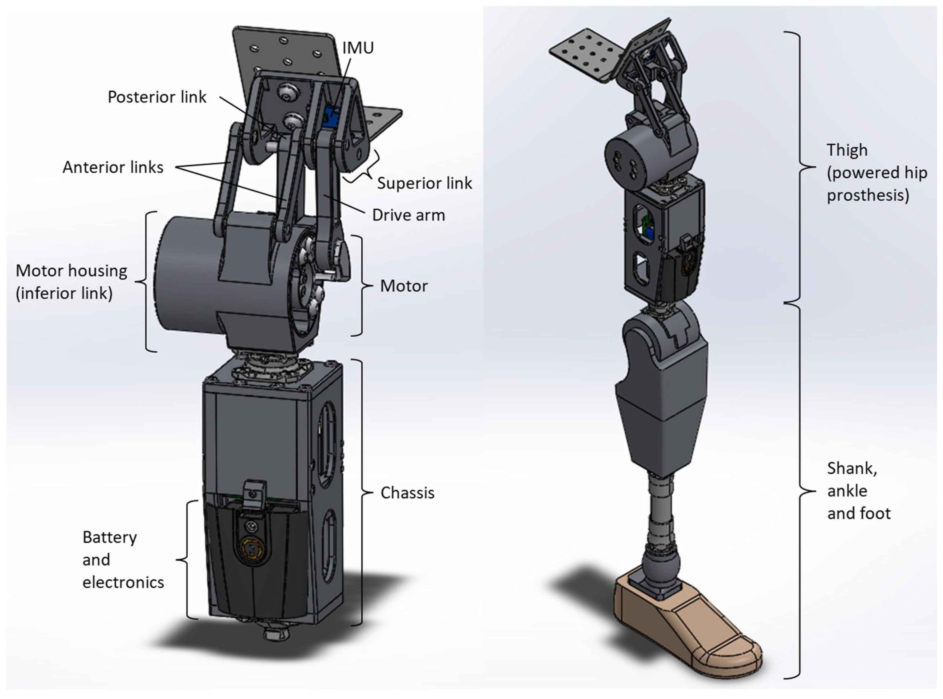
Figure 1. Powered four-bar hip components and integration into a right-side HKAFP.
Prosthesis 07 00105 g001
Figure 2. Powered four-bar hip joint operation and motor components. CW = clockwise, CCW = counterclockwise.
Prosthesis 07 00105 g002
Figure 3. Powertrain linkage optimization process.
Prosthesis 07 00105 g003
Figure 4. Powered four-bar hip motion. Hip flexion angle from the vertical is in blue, motor angle from the motor housing bottom edge is in red, and link dimensions (center to center) are in green. Tin (input torque) and Tout (output torque) are in orange.
Prosthesis 07 00105 g004
Figure 5. Sitting and standing positions of the full-leg prosthesis with the powered four-bar hip.
Prosthesis 07 00105 g005
Figure 6. Powered four-bar hip mechanical advantage (MA) versus hip flexion angle. Mhx is the moment at the hip instantaneous center of rotation (ICR) and Tmx is motor torque. Mhx and Tmx are each a function of hip flexion angle.
Prosthesis 07 00105 g006
Figure 7. Powered four-bar hip prototype: (a) powertrain only, (b) powertrain and chassis.
Prosthesis 07 00105 g007
Figure 8. ISO 15032:2000 static compression tests: (a) A-P extension condition with LH = 134.79 mm and LK = 23.93 mm; (b) M-L condition with LH = 99.96 mm and LK = 57.41 mm.
Prosthesis 07 00105 g008
Figure 9. HKAFP simulator used to reproduce hip amputee gait with able-bodied individuals.
Prosthesis 07 00105 g009
Figure 10. Force and finite element analyses: (a) static equilibrium setup with separated upper and lower units using calculated forces caused by a 96 N-m motor torque; (b) von Mises stress color map of the lower unit medial-lateral cross-section showing maximal stresses on different materials.
Prosthesis 07 00105 g010
Figure 11. ISO 15032:2000 static compression force versus displacement profiles: (a) anterior-posterior (A-P) extension configuration; (b) medial-lateral (M-L) configuration in full hip extension.
Prosthesis 07 00105 g011
Figure 12. Prosthetic pelvic, hip, and knee kinematic data (mean plus-minus one standard deviation for 10 steady-state strides) from participants P1, P2, P3, and the ensemble average.
Prosthesis 07 00105 g012
Figure 13. One prosthetic stride of participant 2 wearing the HKAFP simulator with the powered four-bar hip joint. Gait phase instances from loading response to terminal swing are shown.
Prosthesis 07 00105 g013
Table 1. Anthropometric and demographic information for powered hip walking trial participants.
ParticipantHeight (cm)Weight (kg)Age (Years)
11809529
21789545
31759826
Ensemble178 ± 396 ± 233 ± 10
Table 2. Prosthetic pelvic, hip, and knee ranges of motions and extrema. Mean plus-minus one standard deviation for 10 steady-state strides of each participant and the ensemble average.
ParticipantMin Ant.
Pelvic Tilt (°)
Max Ant.
Pelvic Tilt (°)
Pelvic Range of Motion (°)Max Hip
Extension (°)
Max Hip
Flexion (°)
Hip Range of Motion (°)Max Knee
Extension (°)
Max Knee Flexion (°)Knee Range of Motion (°)
15.19 ± 1.7722.14 ± 2.3416.95 ± 3.327.98 ± 0.1413.28 ± 0.0421.26 ± 0.170.61 ± 0.4347.73 ± 2.4448.34 ± 2.53
20.43 ± 1.6814.70 ± 1.2214.27 ± 2.298.76 ± 0.0612.21 ± 0.0420.97 ± 0.091.23 ± 0.1041.83 ± 2.1343.06 ± 2.19
39.90 ± 1.2322.12 ± 2.3612.22 ± 1.632.71 ± 0.0417.00 ± 0.0819.71 ± 0.071.31 ± 0.1033.58 ± 6.2134.89 ± 6.26
Ensemble5.17 ± 4.2219.65 ± 4.0714.48 ± 3.136.48 ± 2.7414. 17 ± 2.0920.65 ± 0.691.05 ± 0.4141.05 ± 7.0842.10 ± 6.88
Table 3. Mean and plus-minus one standard deviation spatiotemporal parameters for 10 steady-state strides of each participant and the ensemble average.
ParticipantEarly-Stance Double-Support Time (s)Prosthetic Side Single-Support Time (s)Late-Stance
Double-Support Time (s)
Sound Side
Single-Support Time (s)
Sound Step Length (m)Prosthetic Step Length (m)Cadence (steps/min)Walking Speed (m/s)
10.42 ± 0.060.23 ± 0.030.38 ± 0.050.60 ± 0.060.43 ± 0.080.42 ± 0.0477 ± 170.52 ± 0.05
20.46 ± 0.030.25 ± 0.030.42 ± 0.040.56 ± 0.040.45 ± 0.070.43 ± 0.0473 ± 120.52 ± 0.07
30.63 ± 0.130.24 ± 0.040.56 ± 0.090.74 ± 0.070.41 ± 0.060.28 ± 0.0559 ± 150.32 ± 0.06
Ensemble0.50 ± 0.120.24 ± 0.030.46 ± 0.100.63 ± 0.100.43 ± 0.070.38 ± 0.0869 ± 170.45 ± 0.11
Disclaimer/Publisher’s Note: The statements, opinions and data contained in all publications are solely those of the individual author(s) and contributor(s) and not of MDPI and/or the editor(s). MDPI and/or the editor(s) disclaim responsibility for any injury to people or property resulting from any ideas, methods, instructions or products referred to in the content.