
Subgingival Zone Detection via Reverse Subgingival Scan

 ,
,  and
and 
Abstract
:1. Introduction
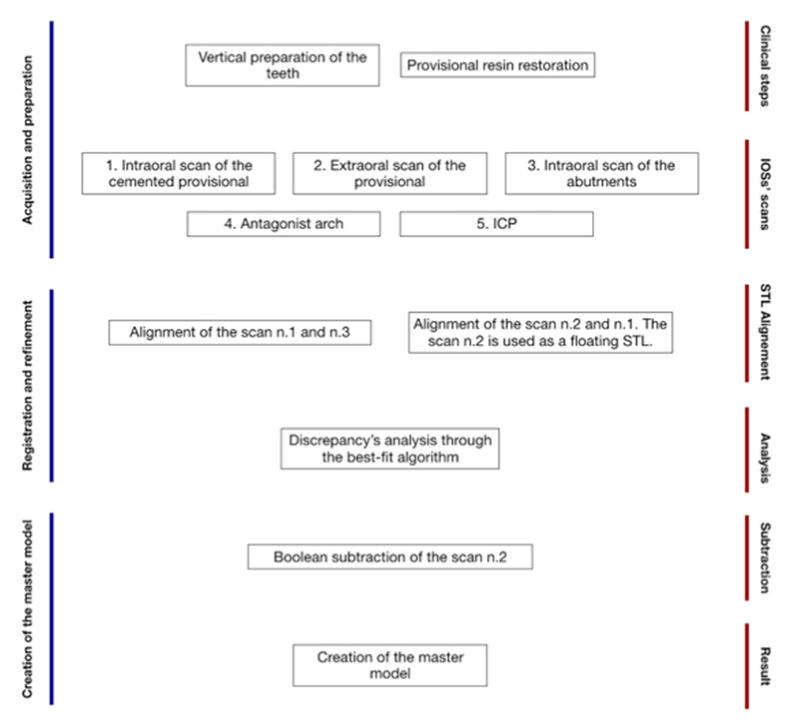
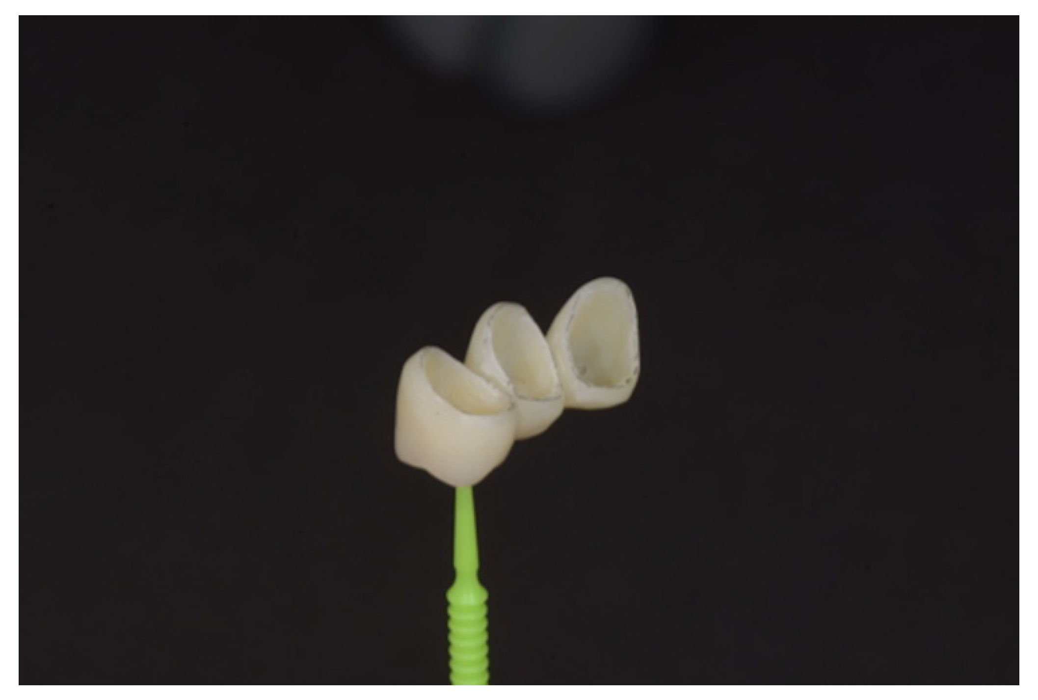
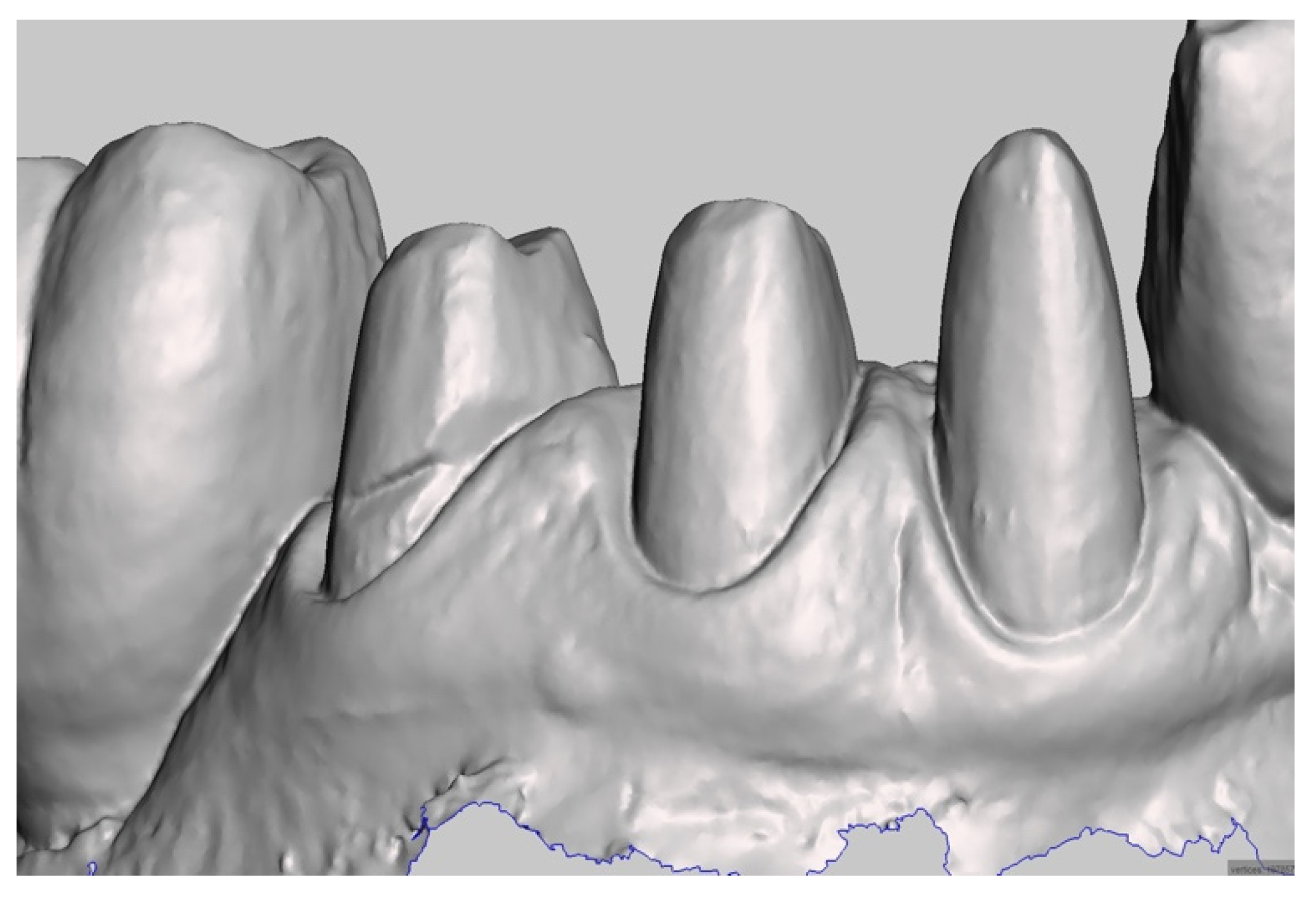
2. Technique
Software Workflow
- Step A: Cleaning STL Files
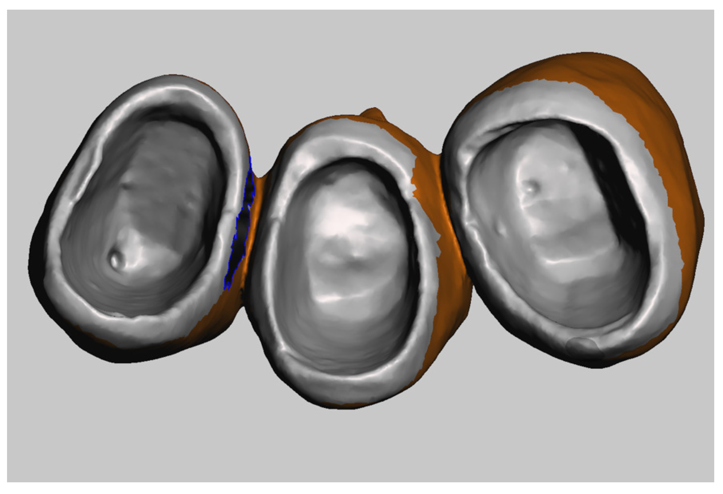
- Step B: Registration of the Scans
- Step C: Creation of the Master Model
3. Discussion
4. Conclusions
Author Contributions
Funding
Institutional Review Board Statement
Informed Consent Statement
Data Availability Statement
Acknowledgments
Conflicts of Interest
References
- Braian, M.; Wennerberg, A. Trueness and precision of 5 intraoral scanners for scanning edentulous and dentate complete-arch mandibular casts: A comparative in vitro study. J. Prosthet. Dent. 2019, 122, 129–136. [Google Scholar] [CrossRef] [PubMed] [Green Version]
- Winkler, J.; Gkantidis, N. Trueness and precision of intraoral scanners in the maxillary dental arch: An in vivo analysis. Sci. Rep. 2020, 10, 1172. [Google Scholar] [CrossRef] [PubMed] [Green Version]
- Nedelcu, R.; Olsson, P.; Nyström, I.; Thor, A. Finish line distinctness and accuracy in 7 intraoral scanners versus conventional impression: An in vitro descriptive comparison. BMC Oral Health 2018, 21, 27. [Google Scholar] [CrossRef] [PubMed]
- Mangano, F.; Gandolfi, A.; Luongo, G.; Logozzo, S. Intraoral scanners in dentistry: A review of the current literature. BMC Oral Health 2017, 17, 149. [Google Scholar] [CrossRef] [PubMed] [Green Version]
- Li, J.; Chen, Z.; Wang, M.; Wang, H.L.; Yu, H. Dynamic changes of peri-implant soft tissue after interim restoration removal during a digital intraoral scan. J. Prosthet. Dent. 2019, 122, 288–294. [Google Scholar] [CrossRef] [PubMed]
- Monaco, C.; Evangelisti, E.; Scotti, R.; Mignani, G.; Zucchelli, G. A fully digital approach to replicate peri-implant soft tissue contours and emergence profile in the esthetic zone. Clin. Oral Implants Res. 2016, 12, 1511–1514. [Google Scholar] [CrossRef] [PubMed]
- Mandelli, F.; Ferrini, F.; Gastaldi, G.; Gherlone, E.; Ferrari, M. Improvement of a Digital Impression with Conventional Materials: Overcoming Intraoral Scanner Limitations. Int. J. Prosthodont. 2017, 4, 373–376. [Google Scholar] [CrossRef] [PubMed] [Green Version]
- Agustín-Panadero, R.; Loi, I.; Fernández-Estevan, L.; Chust, C.; Rech-Ortega, C.; Pérez-Barquero, J.A. Digital protocol for creating a virtual gingiva adjacent to teeth with subgingival dental preparations. J. Prosthodont. Res. 2020, 64, 506–514. [Google Scholar] [CrossRef] [PubMed]


Publisher’s Note: MDPI stays neutral with regard to jurisdictional claims in published maps and institutional affiliations. |
© 2022 by the authors. Licensee MDPI, Basel, Switzerland. This article is an open access article distributed under the terms and conditions of the Creative Commons Attribution (CC BY) license (https://creativecommons.org/licenses/by/4.0/).
Share and Cite
Zingari, F.; Meglioli, M.; Gallo, F.; Toffoli, A.; Macaluso, G.M. Subgingival Zone Detection via Reverse Subgingival Scan. Prosthesis 2022, 4, 234-243. https://doi.org/10.3390/prosthesis4020023
Zingari F, Meglioli M, Gallo F, Toffoli A, Macaluso GM. Subgingival Zone Detection via Reverse Subgingival Scan. Prosthesis. 2022; 4(2):234-243. https://doi.org/10.3390/prosthesis4020023
Chicago/Turabian StyleZingari, Francesco, Matteo Meglioli, Francesco Gallo, Andrea Toffoli, and Guido Maria Macaluso. 2022. "Subgingival Zone Detection via Reverse Subgingival Scan" Prosthesis 4, no. 2: 234-243. https://doi.org/10.3390/prosthesis4020023
APA StyleZingari, F., Meglioli, M., Gallo, F., Toffoli, A., & Macaluso, G. M. (2022). Subgingival Zone Detection via Reverse Subgingival Scan. Prosthesis, 4(2), 234-243. https://doi.org/10.3390/prosthesis4020023