Article

Optimization of the Manufacturing Process by Molding Cobalt-Chrome Alloys in Assembled Dental Frameworks

by
Willi Andrei Uriciuc
1,
Adina Bianca Boșca
2,*,
Anida Maria Babtan
1,
Claudia Nicoleta Feurden
1,
Anca Ionel
1,
Horațiu Vermeșan
3,
Cătălin Ovidiu Popa
3,† and
Aranka Ilea
1,†
1
Faculty of Dental Medicine, “Iuliu-Hațieganu” University of Medicine and Pharmacy, 400012 Cluj-Napoca, Romania
2
Faculty of Medicine, “Iuliu-Hațieganu” University of Medicine and Pharmacy, 400012 Cluj-Napoca, Romania
3
Faculty of Materials and Environmental Engineering, Technical University of Cluj-Napoca, 400641 Cluj-Napoca, Romania
*
Author to whom correspondence should be addressed.
Equal contribution in coordination and validation.
Prosthesis 2021, 3(3), 245-260; https://doi.org/10.3390/prosthesis3030024
Submission received: 29 July 2021 / Revised: 6 September 2021 / Accepted: 6 September 2021 / Published: 10 September 2021

Abstract

:
In oral rehabilitation, the treatment of partial edentulism (PEd) is performed by removable partial dentures (RPD) or assembled prosthetic works (APW) composed of several components, fixed to the prosthetic field (Pa) and a removable one (Pb), in order to facilitate the daily hygiene but also the damping of the occlusal forces applied in mastication. Cobalt-Chromium alloys are materials used to manufacture modern prosthetic assembles. In order for this study to be relevant, it was necessary to standardize the design of the framework (Pa) in terms of shape and volume so that the experiment could be reproducible for the five Co-Cr alloys: 0-A (Co-Cr-Mo), 5-A and 10-A (Co-Cr-Mo-W), 15-A and 16.4-A (Co-Cr-W-Fe) and for the three fabrication methods of dental assembled prosthetic frameworks: refractory duplicate method (RD) resulting removable framework (Pb), direct construction method (DC) resulting removable framework (Pb-) and casting over metal method (CoM) resulting removable framework (Pb+). The time allocated to the adaptation process (AP), mechanical processing and sandblasting, in order to assemble the two components was between 43–70 min, even though the assembly between the Pa-framework and the complementary framework (Pb+) was not necessary, CoM-method hs been provide the elimination of AP step. By applying the arithmetic simple rule of three, the percentages for each of the three methods used were calculated, the values of the difference were obtained. The CoM method improves the joining precision between the components of the removable assembly of prosthetic frameworks by 91.7% compared to the RD method and by 80.62% compared to the DC method. According to the efficiency of the methods used in the precision of joining between frameworks components, their order is: casting over metal, direct construction and refractory duplicate method.

1. Introduction

In oral rehabilitation, the treatment of partial edentulism (PEd) is performed by removable partial dentures (RPD) or assembled prosthetic works (APW) [1]. Most APWs are composed of a partially removable prosthesis that rests on dental crowns (DCs) [2] that are assembled in the oral cavity to compensate for the lost functions of patients with PEd [3].
Cobalt-Chromium alloys are materials used to manufacture modern prosthetic assembles. The attractive characteristics of these materials, as well as the cost price, recommend them as the material of choice for obtaining resistant, durable and innovative prosthetic works [4,5]. The increased hardness and elasticity of the Co-Cr-Mo and Co-Cr-W ternary alloys, called stellates (from “stella” in Latin), introduced in 1907 by Haynes, led to the contemporary version of Co-Cr alloys, used for orthopedic and dental prosthetics. Also, stellates are non-magnetic alloys with excellent biocompatibility and good mechanical and surface properties [6], but also increased resistance to wear and corrosion [7,8,9]. The processing of dental alloys for manufacturing prosthetic metal structures is defined by their technological properties [10].
The biocompatibility of dental alloys is a critical issue, because the alloys are, for a long time, in intimate contact with the tissues in the oral cavity [11].
In order to ensure biological safety [12], the most important property of alloys is the corrosion resistance in the oral cavity [13]. Systemic and local toxicity, allergies and carcinogenic potential are the result of metallic elements [14] that were released from the alloy into the oral cavity by corrosion. Experimental data showed that alloys can cause both systemic toxicity and local toxic effects, since the tissues adjacent to the alloy are exposed to a much higher concentration of metal ions [15]. The issue of biocompatibility is related to this study by the ability of cobalt-chromium alloys to generate a passive layer on the surface of the prosthetic structures. [16]. There are multiple alloys processing methods for manufacturing prosthetic structural components. Thus, we can mention the classic and established method of melting and casting alloy ingots in the refractory mold obtained by melting construction wax [5].
The accessibility of the melting and casting processing method makes these materials suitable for a wide range of uses. The durability of cast prosthetic structures represents the ability of the material to preserve its properties in the functional context, but also in the environment in which it was designed to be used [17,18,19].
The first report of Co-Cr alloys processing by refractory casting was in 1936, thirty years after William Taggart practically invented the method of casting inlays using gold. However, the casting method or the lost wax method is still popular in dental technique [5,20]. This method is time consuming and involves considerable variables related to the technological process [21]. Following the direct construction method (DC) as well as the refractory duplicate method (RD), results a structural component that requires mechanical adaptation to merge into a prosthetic assembly of structures. [5].
The method of casting over metal (CoM) is a method that wants to undermine the refractory duplicate and the mechanical adaptation in order to assemble the prosthetic frameworks components, increasing the joining precision between the assembled prosthetic works (APW) and reducing the working time that is usually llocated to obtain the joining precision between the prosthetics frameworks.

2. Materials and Methods
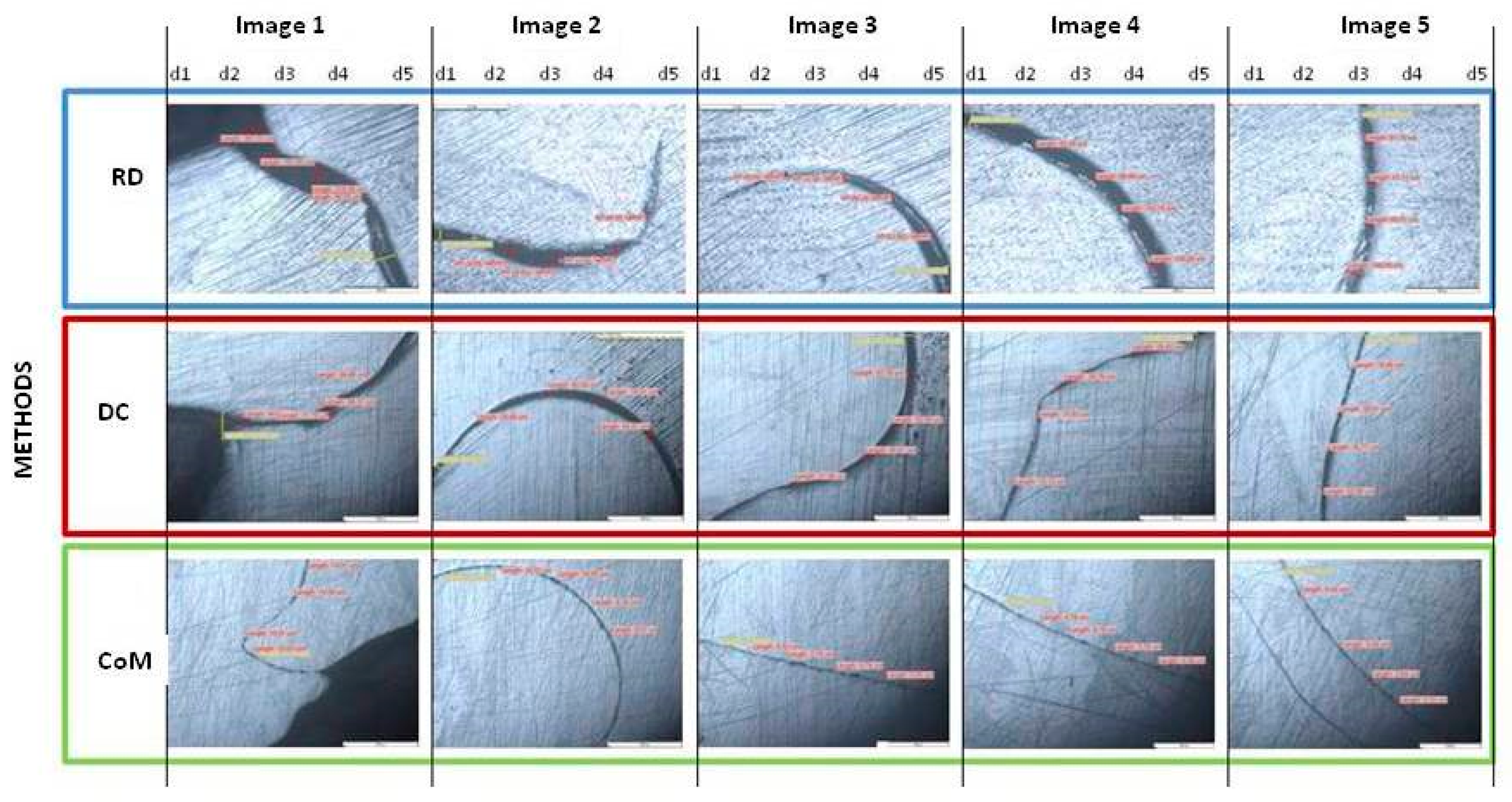
The materials used for analysis were dental frameworks fabricated from casting Co-Cr alloys. Dental alloys are delivered by industrial alloy manufacturers in the form of metal cylinders with a section diameter (d) of 0.5 cm2 and height (h) of 0.8 cm. These alloys are used as raw material in dental laboratories and will be used as starting samples in experimental activity.
The alloys that we used were different in terms of both the mass percentage of each main alloying element (Co, Cr) and the secondary alloying elements (Mo, W, Fe). These can be identified under the trade name: Super C alloy (Dental Alloy Products) called 0-A (Co-Cr-Mo), Wirobond C alloy (Bego Gmbh) called 5-A (Co-Cr-Mo-W), Heraenium P alloy (Heraeus Kulzer) called 10-A (Co-Cr-Mo-W), Heraenium Pw alloy (Heraeus Kulzer) called 15-A (Co-Cr-W-Fe) and Starloy Soft (Dentsply) alloy called 16.4-A (Co-Cr-W-Fe).
The components of the alloys and their percentages in the alloys is presented in Table 1.
The properties of each alloy are different, depending on the alloying elements and their mass percentage in the alloy (Table 2).
Prosthetic frameworks are unique elements, customized according to the particular features of each patient (Figure 1).
In order for this study to be relevant, it was necessary to standardize the design of the fixed framework (Pa) in terms of shape and volume so that the experiment could be reproducible for the all five alloys introduced in study and for three methods used to fabricate complementary frameworks (Pb).
The experimental activity on unique framework can only be relevant by constructing a standard framework and reproducing it in series mode to ensure experimental reproducibility.
P-type standard frameworks were mechanically prepared by guided milling of the assembly area, using a parallel milling machine (AF-350—Amann Girrbach-Austria) and mechanically polished.
During milling, the assembly surface of the P-type framework was rectified in order to obtain a non-retaining surface (≥0°).
The milling of the assembly surface of the cast framework was done in a single vertical axis using metal cutters mounted in the chuck of the AF350 machine micromotor.
The rectification protocol involved the entire assembly surface of the P framework, starting with the vertical wall and the lower sill, the bilateral wells and the upper shoulder.
The milling of the vertical wall was performed using a cylindrical milling cutter with an active hemispherical head. By milling, the semi-round threshold was profiled with the rectification of the wall surface (Figure 2).
Figure 2b shows the difference in surface texture between the cast framework and the milled ground surface (0°). The semi-round profiled sill was formed by inserting the drill into the P framework the depth of ½ of its thickness (Figure 2c). The P framework was positioned as parallel as possible to the vertical axis of the drill (Figure 2a).
The milling of the shoulder at an angle of 2–3° profiled a second vertical wall. The shoulder direction followed a contour in the shape of “Ω” in order to obtain a unique axis for coupling the complementary parts to the detachable assembly of prosthetic framework (Figure 3).
At the left and right extremities of the assembly surface, two vertical wells were ground by milling. Milling was done using a cylindrical milling cutter with a straight, inactive head (Figure 3).
After rectifying the assembly surface by milling, it was polished until the mirror texture was obtained (Figure 3d). The protocol was performed for both P cast frameworks.
For the shape design reproducibility of the framework included in the study, the P framework was imprinted in silicone for duplication.
The series production of the models for the P framework was done in a silicone mold, using polymethyl methacrylate (powder: monomer) (Figure 4).
Ma framework wax models were coated in refractory material (Bellavest SH, Bego Goldschlagerei Gmbh, Bremen, Germany) and heat treated to obtain the refractory mold. In the refractory mold, the Pa frameworks were casted in molten alloy in series mode for each of the 5 alloys under study (Figure 5).
For each Pa framework (0-Pa, 5-Pa, 10-Pa, 15-Pa and 16.4-Pa), a complementary frameworks was obtained, using three different methods:
-
refractory duplicate method (RD)
(0-Pb, 5-Pb, 10-Pb, 15-Pb, 16.4-Pb)
-
direct construction and framework detachment method (DC)
(0-Pb-, 5-Pb-, 10-Pb-, 15-Pb-, 16.4-Pb-)
-
direct casting over metal method (CoM)
(0-Pb+, 5-Pb+, 10-Pb+, 15-Pb+, 16.4-Pb+)

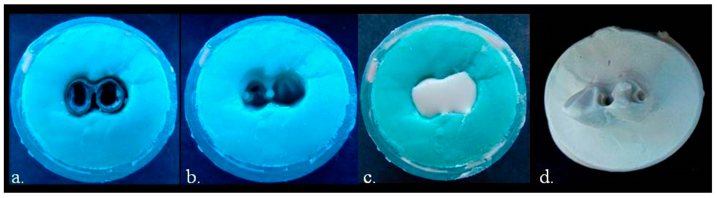
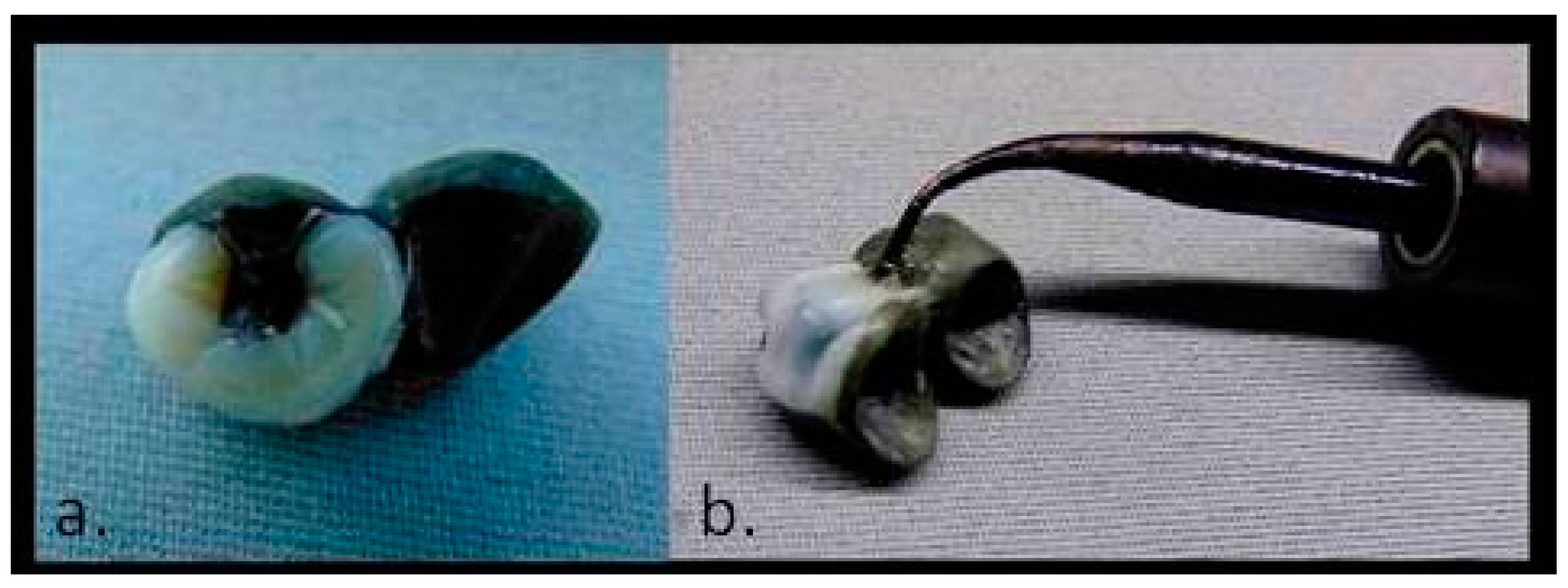
2.1. Refractory Duplicate Method-RD

The complementary framework was obtained by the refractory duplicate method, based on a duplicate composed of refractory material for the framework Pa.
The duplicating impression was made by putting silicone in a conformer, over the Pa framework that was positioned at the base of the conformer (Figure 6a). After the silicone had seting, the conformer was opened, and the Pa framework was removed by extraction from the silicone (Figure 6b).
These methods try to transpose a positive relief into a negative mold, from a metal part to another metal part by using a refractory duplicate.
The refractory duplicate was made by inserting the material into the duplicating impression (Figure 6c). After the material had set, it was extracted from the impression (Figure 6d).
The complementary framework wax model was built on the assembly surface of the refractory duplicate so that it retrieved the relief of the assembly surface in the negative shape (Figure 7).
The complementary framework wax model was coated together with the refractory duplicate, in order not to be deformed during handling or due to the heat, as it was made of wax. By heating, the coating was transformed into a refractory mold.

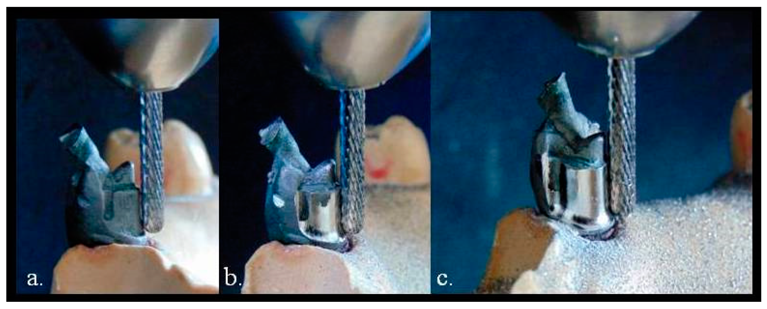
2.2. Direct Construction and Framework Detachment Method-DC

The hypothesis of the most accurate transposition of the relief of the assembly surface from the Pa framework to the complementary framework must involve a method as direct as possible. Therefore, the fabrication of born-out acrylic resins model, by direct construction on the assembly surface of Pa framework, will copy the positive relief on the internal surface of the Mb- framework resin model and transferred in a negative refractory mold.
The acrylic resin material was deposited on assembly surface of Pa framework (Figure 8a) using a metal tool (Figure 8b), and after the setting of the material (Figure 8c), the Mb- framework resin model was detached from the assembly surface of the Pa framework (Figure 8d). If the assembly surface is retentive, the Mb- resin model is damaged during the detachment from the Pa framework. Then is necessary to rectify the Pa framework assembly surface and to repeat the resin construction maneuver, in order to validate the nonretentive shape of the assembly surface.
The resin deposited on by construction the assembly surface has no exothermic reaction during the setting of the material, and thus, the deformation at the transition from plastic phase to solid phase is minimal (Figure 8e).
The geometry of the assembly surface was transferred to the refractory material using the Mb- resin model that was coated, in order to achieve the refractory mold. Similar to the refractory duplicate method, the material errors occur during the coating of the refractory material and cooling of the molten and cast alloy. The complementary cast framework Pb- requires mechanical processing by cutting in order to adjust the insertion and assembled with Pa framework.

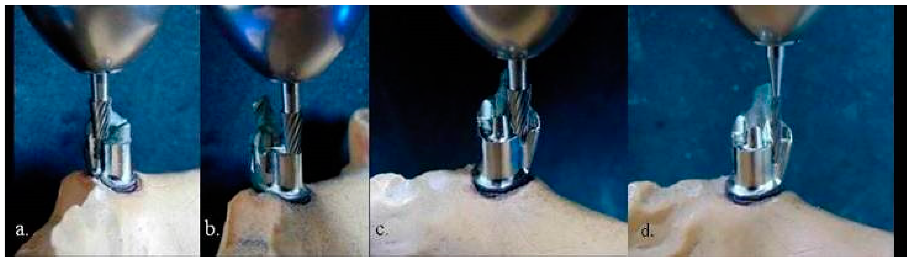
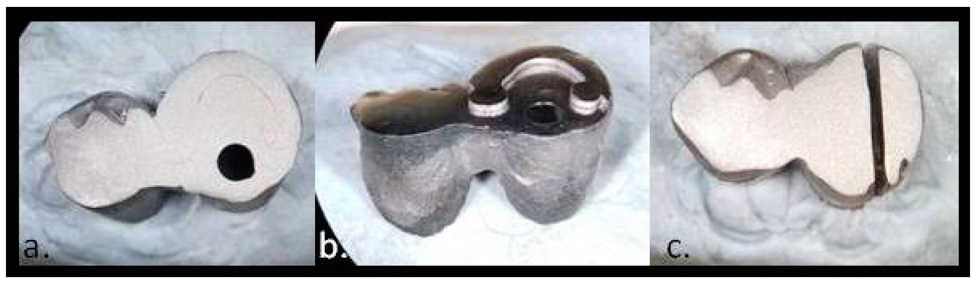
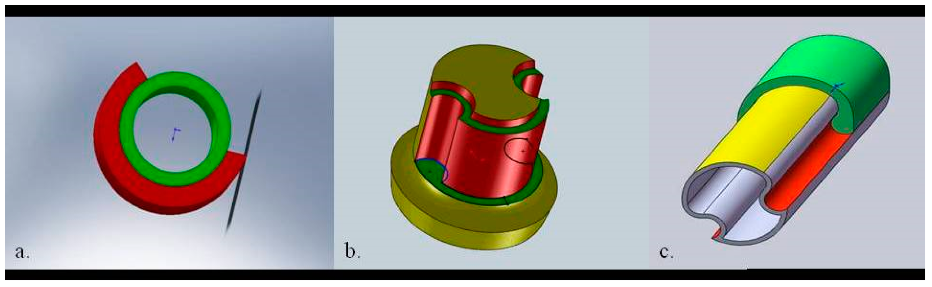
2.3. Casting over Metal Method—CoM

In the hypothesis of transferring the geometry of the assembly surface from the Pa framework to the complementary framework, the use of a method by which the molten alloy is cast in the mold directly over the assembly surface of the Pa framework was tested.
Thus, the direct wax construction of the Mb+ wax model was performed on the assembly surface of the Pa framework (Figure 9b).
The Mb+ wax model did not detach from the assembly surface of the Pa framework, after the completion of the framework (Figure 9a).
The framework was coated in refractory material together with the Pa framework in the assembled position with the Mb+ wax model.
The steps for obtaining the refractory mold by heat treatment of the coating were performed. The molten alloy was cast into the refractory mold which also contained the Pa insert framework.
The molten alloy came into contact with the assembly surface of the Pa framework and directly took its shape. The cooling of the complementary cast framework was made in contact with the Pa framework, thus resulting an assemble of frameworks.

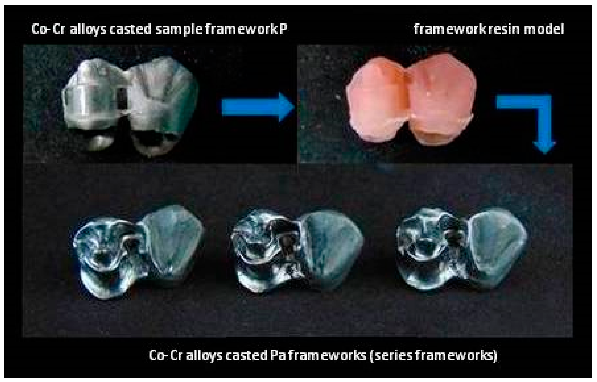
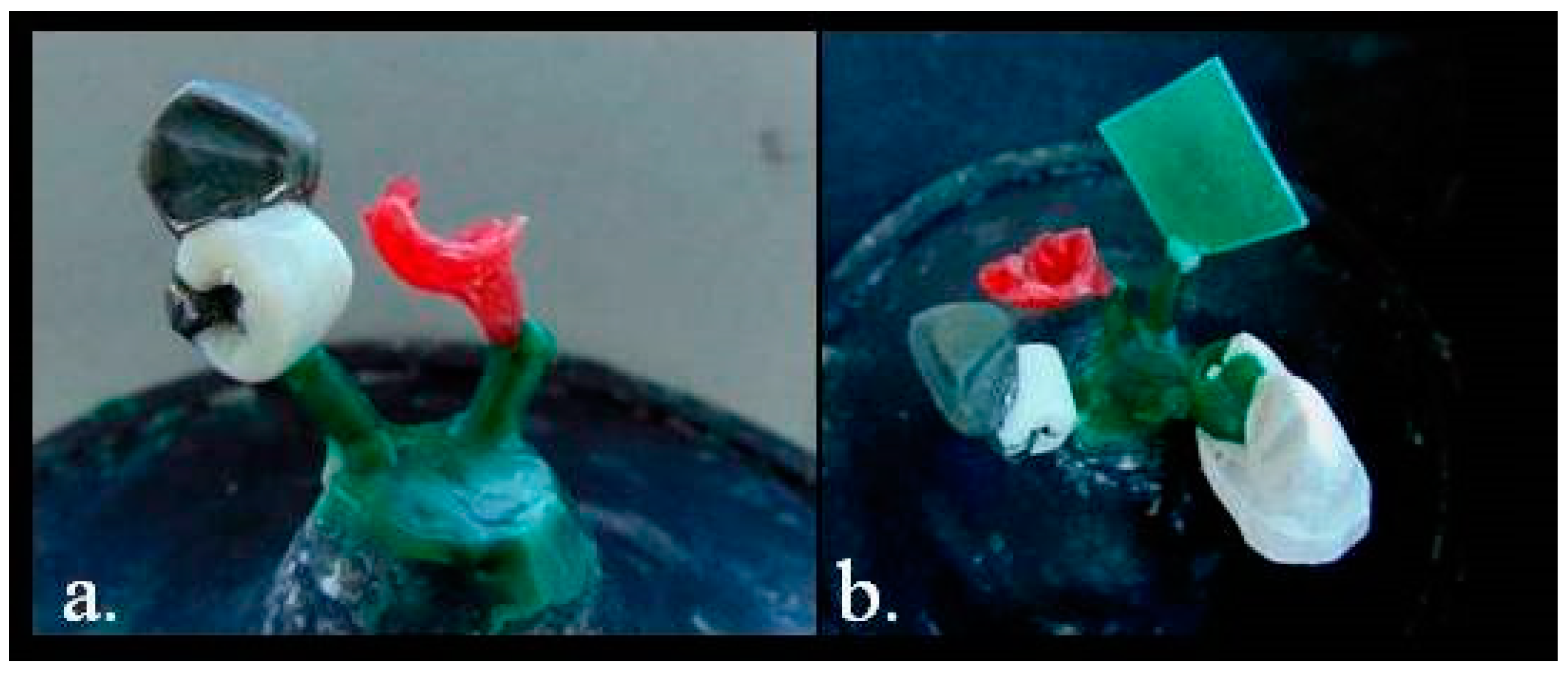
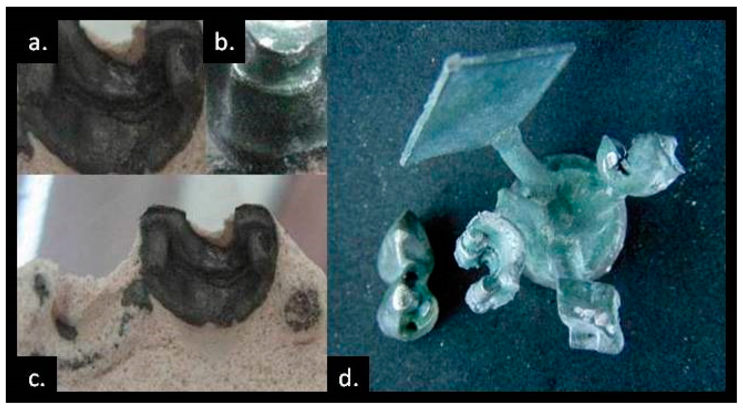
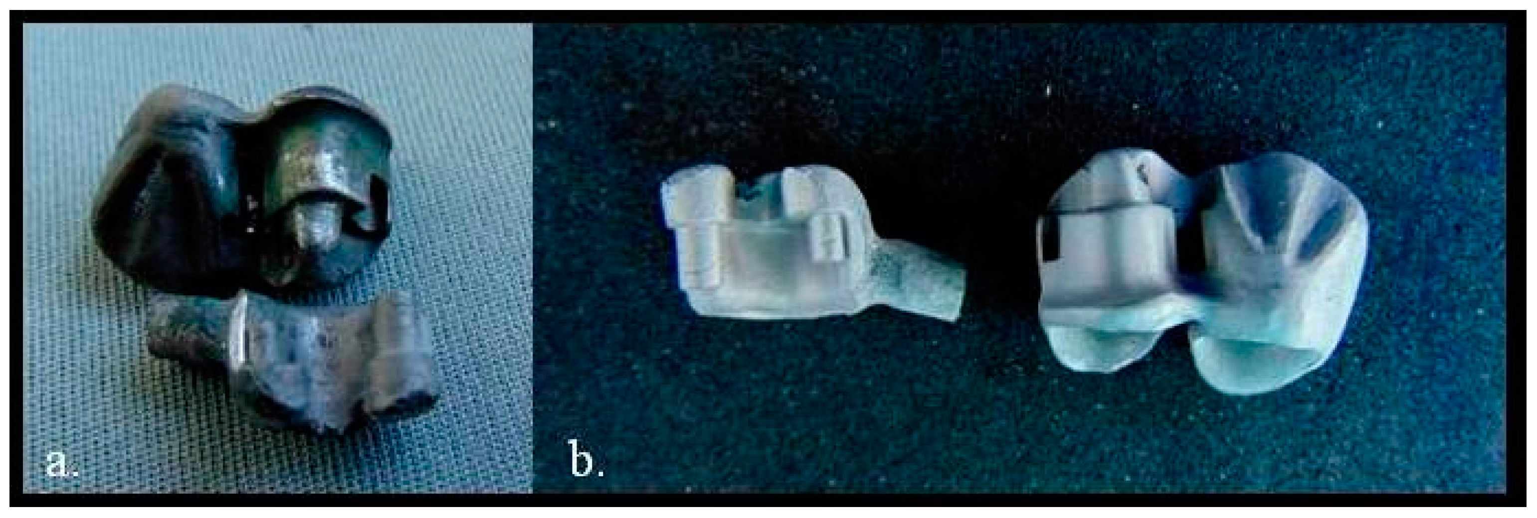
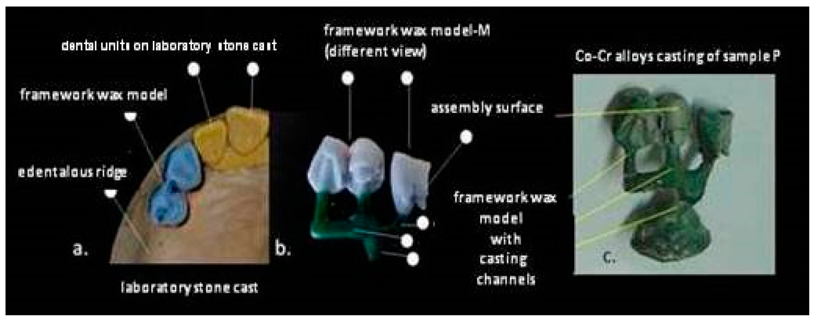
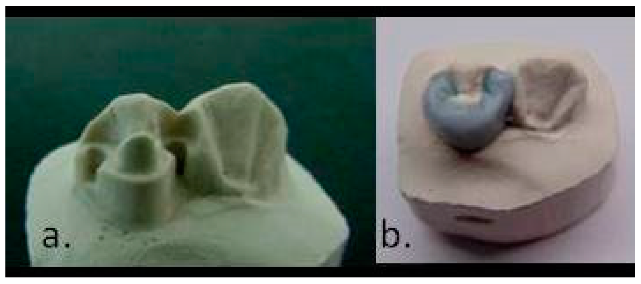
2.4. Fabrication of the Casting Mold Based on the Born-out Models Obtained by the 3 Proposed Methods

The born-out models of the complementary frameworks, made by the three construction methods, were coated together, in order to obtain five refractory molds, one for each of the five alloys under study.
Thus, the following born-out models were prepared for coating (Figure 10):
-
the wax model of the complementary framework modeled indirectly, on the refractory duplicate (Mb/dPa)
-
the resin model of the complementary framework modeled directly on the Pa framework and detached after layout (Mb-/Pa)
-
the wax model of the complementary framework modeled directly on the Pa framework and not detached after layout (Mb+ Pa)
After transforming the coating into a refractory mold using a furnace (Meditherm 100MP, Bego Goldschlagerei Gmbh, Bremen, Germany), all five alloys were melted and casted into the moulds using an induction melting dental casting machine (Fornax T, Bego Goldschlagerei Gmbh., Bremen, Germany).
After the alloy casting step, the molds with the alloy cast inside were allowed to cool slowly until the temperature equilibrated with ambient temperature.
Detachment of the casting pieces from the mold was done by damaging the mold by mechanical methods; then, the casting was cleaned by blasting with aluminum oxide (Al2O3) with a granulation size of 175 µm using a fine sandblasting unit (Basic classic, Renfert, Europe).
The following complementary frameworks were found attached to the casting cone (Figure 11):
-
dPb (complementary framework modeled on the refractory duplicate dPa);
-
Pb- (complementary framework modeled directly on the Pa framework and detached);
-
Pb+ (complementary framework modeled directly on the Pa framework and coated together with it);
-
Pa (insert framework Pa, which was part of the refractory mold in order to cast the Pb+ framework).
After detachment from the mold, the Pa framework remained included in the casted piece. The Pa framework was subjected to percussion blows in the vertical axis, in order to detach it from the complementary framework (Pb+) to which it was assembled (Figure 11).
For three Co-Cr alloys (5-A, 10-A and 15-A), the complementary frameworks (5-Pb+, 10-Pb+ and 15-Pb+) ws successfully detached from the assembly surface of the Pa frameworks (5-Pa, 10-Pa and 15-Pa) (Figure 12a) and fine sandblasted (Figure 12b).
Deformations of the complementary framework dPb and Pb- were identified (Figure 13a); therefore, the assembly surface had to be adjusted by mechanical processing in order to make possible the insertion and assembly of the frameworks(Figure 13).
For this purpose, a powder spray was used (Figure 13b-green). The deformed area was marked by spraying the assembly surface of the Pa framework followed by the insertion of the complementary framework (dPb or Pb-). By mechanical processing with metal cutters, rotatably driven on the chuck of a dental laboratory micromotor (Forte 200α, ShaeShin, Korea), the gradual and progressive assembly of the two structures was performed (Figure 13d,e).
Re-assembly of the complementary framework Pb+ with the Pa insert framework, in the cases of 3 alloys (5-A, 10-A and 15-A) did not require mechanical adjustments. By polishing the assembly surfaces at the level of both components of the removable assembly of prosthetic frameworks, the joint could be considered passive (Figure 14a,b).
For the 0-A and 16.4-A alloy castings, the detachment of the complementary frameworks (0-Pb+ and 16.4-Pb+) from the Pa insert frameworks (0-Pa and 16.4-Pa) was not possible (Figure 14c).
The two complementary frameworks were assembled non-detachably (Figure 14c) after direct casting of the alloy over the assembly surface of the Pa insert framework; although the retentivity test was negative, the Mb- resin model (0-Mb- and 16.4-Mb-) was successfully detached from the assembly surface (Figure 8e).
For the 0-A and 16.4-A alloys, it was not possible to perform the assembly tests for the frameworks made by the other two methods than CoM method, because the Pa insert frameworks (0-Pa and 16.4-Pa) remained captured in the casting complementary framework (Figure 14c).
Detachment of the Pa insert frameworks (5-Pa, 10-Pa and 15-Pa) from the casting enabled the testing of the assembly with the other complementary cast frameworks as dPb (5-dPb, 10-dPb, 15-dPb) and Pb- (5-Pb-, 10-Pb-, 15-Pb-) (Figure 14b).
The process of adjusting the insertion and assembling the components of the assembled prosthetic frameworks is still available for 3 from 5 alloys remined in the remaining in the study (5-A, 10-A and 15-A). The time of the process has been measured by a digital chronometer, providing the time consuming in the dental laboratory for those activities.
After all the prosthetic framework assembles has been in the position assembled stage, they were horizontally rotary cuting using a 0.5 mm rotary silicon carbide (SiC) disc at speed of 15,000 rpm and then finished using sandpaper (500, 1200), so that they could be analyzed at the assembled area between components.
Using the specific Software (Soft Imaging System, Olympus) attached to the stereo microscope (Olympus GX51), micrographic segments were captured and the gaps were measured. The measurements were made on micrographic segments at 200× magnification.

3. Results

The time allocated to the adjustment process (mechanical processing and sandblasting) in order to assemble the two components was between 43-70 min, even though the assembly between the Pa framework and the complementary framework Pb+ was not necessary (dPb and Pb-), CoM method (Pb+) facilitating the elimination of this step.
For the 0-A and 16.4-A alloys (Table 3-red) the adjustment could not be performed because the Pa framework remained captured in the casting of the complementary framework. The adjustment processes for the 15-A alloy cast framework obtained the best times 43 min true DC method and 51 min, through RD method. The adjustment process for the 10-A alloy cast frameworks required the longest times, 56 min for the framework fabricated through the DC method and 70 min for the framework fabricated through the RD method. The adjustment processes for the cast frameworks of 5-A alloy required average times, 54 min for the framework fabricated through DC method and 48 min for the framework fabricated through RD method.
The working times required for the adjustment of the complementary framework to the assembly surface of the Pa framework that are presented in Table 3.
Regardless of the 3 alloys (5-A, 10-A or 15-A), the complementary structure Pb+ did not require adaptation (green). The descending order of the time required for the adaptation process overlapped with the hardness of the alloys under study (Table 4).
For 3 assemblies of prosthetic framework made by 3 methods (RD, DC and CoM) were analyzed, five images that represent segments of sections (Image 1, Image 2, Image 3, Image 4 and Image 5) with 5 measurements (d1, d2, d3, d4 and d5) in (µm) (Figure 15) (Table 5, Table 6, Table 7 and Table 8) were analyzed.

4. Discussion

Regarding the limitations of this study, in terms of assembled prosthetic structures, their components are uniquely made for each individual patient.
The high precision of joining between the components of the set of prosthetic structures can be considered a major plus in the comfort of wearing the prosthetic work by the patient.
New research can be directed towards managing the precision of joining between prosthetic structures but also the degree of freedom between them so that its assembly can be a non-traumatic process for the tissues involved in the dental prosthetic field.
Another direction of development and application of CoM method can be the fabrication of articulated spherical assembly.
About the geometry of classical frameworks’ assemble, the shape of assembling surface is important and ensures the stability of the assembly of the two joined components (Figure 16).
In terms of electro-chemical stability of Co-Cr casted alloys, they remain materials of choice in the manufacture of prosthetic frameworks. The design of the alloy in terms of the proportion of alloying elements (Co, Cr, Mo, Fe, W), determines a high stability of the material in the oral cavity.
After processing the Co-Cr alloy by melting and casting, the properties of the material are preserved.

5. Conclusions

CoM method optimized the working times of the technological process, by eliminating the adaptation of complementary structures for assembly.
CoM method is valid only for three out of the five studied Co-Cr alloys, due to the mass percentage of Tungsten an element between 5–15%wt as alloying.
The hardness at the surface of the cast framework influenced the time required for the adjustment proces, in order to assemble the framework components.
DC method was more efficient than RD method, in terms of the required time.
CoM method improves the joining precision between the assembled components of the framework prosthetic by 91.7% compared to RD method and by 80.62% compared to DC method. The difference between the classic RD method and DC method is 57.56%.

Author Contributions

Conceptualization, W.A.U.; Formal analysis, A.M.B., C.N.F. and A.I. (Anca Ionel); Investigation, W.A.U., A.M.B. and H.V.; Methodology, W.A.U.; Project administration, W.A.U.; Software, C.N.F.; Visualization, A.B.B.; Writing—original draft, W.A.U.; Coordination and validation of Manuscript, C.O.P. and A.I. (Aranka Ilea) (equal contribution). All authors have read and agreed to the published version of the manuscript.

Funding

This study was supported partially by project CNCS-UEFISCDI, PN-III-P2-2.1-PED-2019-3664—“Personalized intelligent matrices for tissue regeneration and meta-inflammation control” (PRIM_TISS), No 348PED/03.08.2020.

Conflicts of Interest

The authors declare no conflict of interest.

References

  1. Davenport, J.; Basker, R.; Heath, J.; Ralph, J.; Glantz, O. Removable partial dentures: An introduction. Br. Dent. J. 2000, 189, 414–424. [Google Scholar] [CrossRef] [PubMed] [Green Version]
  2. Pellizzer, E.P.; Mazaro, J.V.Q.; Verri, F.R.; Antenucci, R.M.F.; Goiato, M.C. Removable Partial Denture in Combination with a Milled Fixed Partial Prosthesis as Interim Restorations in Long-Term Treatment. J. Prosthodont. 2010, 19, 77–80. [Google Scholar] [CrossRef] [PubMed]
  3. Franks, A.S.T. The concept of oral rehabilitation. J. Oral Rehabil. 1976, 3, 1–8. [Google Scholar] [CrossRef] [PubMed]
  4. Viennot, S.; Dalard, F.; Malquarti, G.; Grosgogeat, B. Combination fixed and removable prostheses using a CoCr alloy: A clinical report. J. Prosthet. Dent. 2006, 96, 100–103. [Google Scholar] [CrossRef] [PubMed]
  5. Uriciuc, W.A.; Vermesan, H.; Tiuc, A.E.; Ilea, A.; Bosca, A.B.; Popa, C.O. Casting over Metal Method Used in Manufacturing Hybrid Cobalt-Chromium Dental Prosthetic Frameworks Assembles. Materials 2021, 14, 539. [Google Scholar] [CrossRef] [PubMed]
  6. Uriciuc, W.A.; Vermeşan, H.; Botean, A.I.; Nistor, L.; Popa, C. Research on the surface of the dental alloys with cobalt-crom base. In Acta Technica Napocensis; Series: Applied Mathematics, Mechanics, and Engineering; Tehnical University of Cluj-Napoca: Cluj-Napoca, Romania, 2019; Volume 62, ISSN 2393-2988. Available online: https://atna-mam.utcluj.ro/index.php/Acta/article/view/1244 (accessed on 9 September 2021).
  7. Al Jabbari, Y.S. Physico-mechanical properties and prosthodontic applications of Co-Cr dental alloys: A review of the literature. J. Adv. Prosthodont. 2014, 6, 138. [Google Scholar] [CrossRef] [PubMed] [Green Version]
  8. Haynes, E. Metal Alloy; U.S.P. Office: Washington, DC, USA, 1907. [Google Scholar]
  9. Chiba, A.; Nomura, N.; Ono, Y. Microstructure and mechanical properties of biomedical Co–29CrMo alloy wire fabricated by a modified melt-spinning process. Acta Mater. 2007, 55, 2119–2128. [Google Scholar] [CrossRef]
  10. Chiba, A.; Kumagai, K.; Nomura, N.; Miyakawa, S. Pin-on-disk wear behavior in a like-on-like configuration in a biological environment of high carbon cast and low carbon forged Co–29Cr–6Mo alloys. Acta Mater. 2007, 55, 1309–1318. [Google Scholar] [CrossRef]
  11. Kajima, Y.; Takaichi, A.; Nakamoto, T.; Kimura, T.; Yogo, Y.; Ashida, M.; Doi, H.; Nomura, N.; Takahashi, H.; Hanawa, T.; et al. Fatigue strength of Co–Cr–Mo alloy clasps prepared by selective laser melting. J. Mech. Behav. Biomed. Mater. 2016, 59, 446–458. [Google Scholar] [CrossRef] [PubMed]
  12. Padrós, R.; Punset, M.; Molmeneu, M.; Velasco, A.B.; Herrero-Climent, M.; Rupérez, E.; Gil, F.J. Mechanical Properties of CoCr Dental-Prosthesis Restorations Made by Three Manufacturing Processes. Influence of the Microstructure and Topography. Metals 2020, 10, 788. [Google Scholar] [CrossRef]
  13. Wataha, J.C.; Schmalz, G. Dental Alloys. In Biocompatibility of Dental Materials; Springer: Berlin/Heidelberg, Germany, 2009; pp. 221–254. [Google Scholar] [CrossRef]
  14. Kassapidou, M.; Franke Stenport, V.; Hjalmarsson, L.; Johansson, C.B. Cobalt-chromium alloys in fixed prosthodontics in Sweden. Acta Biomater. Odontol. Scand. 2017, 3, 53–62. [Google Scholar] [CrossRef] [PubMed]
  15. Lucchetti, M.C.; Fratto, G.; Valeriani, F.; De Vittori, E.; Giampaoli, S.; Papetti, P.; Spica, V.R.; Manzon, L. Cobalt-chromium alloys in dentistry: An evaluation of metal ion release. J. Prosthet. Dent. 2015, 114, 602–608. [Google Scholar] [CrossRef] [PubMed]
  16. Uriciuc, W.A.; Vermeșan, H.; Boșca, A.B.; Ilea, A. Interaction of Saliva with Cobalt-Chromium-Based Dental Alloys in Casted Prosthetic Pieces. Curr. Trends Biomed. Eng. Biosci. 2018, 14, 555882. [Google Scholar] [CrossRef]
  17. Evans, E.J.; Thomas, I.T. The in vitro toxicity of cobalt-chrome-molybdenum alloy and its constituent metals. Biomaterials 1986, 7, 25–29. [Google Scholar] [CrossRef]
  18. Mercieca, S.; Caligari Conti, M.; Buhagiar, J.; Camilleri, J. Assessment of corrosion resistance of cast cobalt- and nickel-chromium dental alloys in acidic environments. J. Appl. Biomater. Funct. Mater. 2017, 16, 47–54. [Google Scholar] [CrossRef] [PubMed] [Green Version]
  19. Okazaki, Y.; Gotoh, E. Comparison of metal release from various metallic biomaterials in vitro. Biomaterials 2005, 26, 11–21. [Google Scholar] [CrossRef] [PubMed]
  20. Uriciuc, W.A. Research about Precision Casting of Removable-Fixed Ensemble Applied in Dental Prosthodontics. In Proceedings of the International Conference on Advancements of Medicine and Health Care through Technology, Cluj-Napoca, Romania, 23–26 September 2009; Vlad, S., Ciupa, R.V., Nicu, A.I., Eds.; Springer: Berlin/Heidelberg, Germany; Volume 26. [Google Scholar] [CrossRef]
  21. Van Noort, R. Introduction to Dental Materials; Elsevier: Amsterdam, The Netherlands, 2013. [Google Scholar]
  22. Dental Alloys Products, Property Chart. Available online: http://www.alloysonline.com/DAP/html/ENGLISH/daprodlookup/ro_productlookup.html (accessed on 14 June 2021).
  23. Bego Product Catalogue. Available online: https://www.bego.com/conventionalsolutions/alloys/product/Category/list/category/23/ (accessed on 13 June 2021).
  24. Kulzer: Co-Cr Base Alloy (Heraenium P). Available online: https://www.kulzer.com/int2/en/products/heraenium-p-for-cand-b.html (accessed on 13 June 2021).
  25. Kulzer: Co-Cr Base Alloy (Heraenium PW). Available online: https://www.kulzer.com/en/en/products/heraenium-pw-for-cand-b.html (accessed on 13 June 2021).
  26. Dentsply Sirona Prosthetics: Non Precious Metal Alloys. Available online: https://www.dentsplysirona.com/content/dam/dentsply/pim/manufacturer/Prosthetics/Fixed/Alloys/CoCr_Alloys/StarLoy_C/PR%20StarLoy_EN.pdf (accessed on 14 June 2021).
Figure 1. (a). Framework of structure P on the laboratory cast; (b). Preparation of the framework for coating and obtaining the refractory mold, by attaching the frameworks of the casting channels; (c). Sample P.
Prosthesis 03 00024 g001
Figure 2. (a). The casting of P structure before milling; (b). The P structure during milling; (c). The surface of the vertical wall rectified by milling.
Prosthesis 03 00024 g002
Figure 3. (ac). Milling of the shoulder m (different perspectives); (d). Bilateral milling of vertical wells.
Prosthesis 03 00024 g003
Figure 4. (a). Preparation of the P framework in the cylindrical shaper; (b). The silicone material into the conformer, over framework P; (c). Framework P from the duplicating mold; (d). Mold for the internal shape of the model; (e). Mold for the external shape of the model; (f). Preparation of the resin material in the plastic phase; (g). Material into the mold; (h). Mold mounting in a mechanical press system by screw; (i). Framework after the setting of the layout material; (j). Framework with press burrs.
Prosthesis 03 00024 g004
Figure 5. Diagram of the transition from framework P (individual framework) to the series production of Pa frameworks by using the Ma framework wax model.
Prosthesis 03 00024 g005
Figure 6. (a). Duplication of the Pa framework; (b). duplicating impression; (c). insertion of the refractory material in the duplicating impression; (d). refractory duplicate dPa.
Prosthesis 03 00024 g006
Figure 7. (a). The refractory duplicate of the Pa framework; (b). Making the model for the complementary framework Pb.
Prosthesis 03 00024 g007
Figure 8. (a). Pa framework; (b). Deposition of resin material on the assembly surface of the Pa framework; (c). Making the handle and setting of the material; (d). Detachment by traction of the resin model from the assembly surface; (e). Framework resin model of the detached Pb framework (indicating a non-retentive assembly surface).
Prosthesis 03 00024 g008
Figure 9. (a). Direct wax-based construction, without detachment of the framework (Mb +); (b). construction method of waxing up.
Prosthesis 03 00024 g009
Figure 10. (a). The Mb+ wax model and the Pa framework, Mb- resin model, prepared for coating by connecting the casting channels to the model; (b). The DMb wax model ready for coating together with the refractory duplicate.
Prosthesis 03 00024 g010
Figure 11. (a,c). The assembly surface of the Pb+ framework after detachment from the mold; (b). The assembly surface of the Pa framework after detachment from the mold; (d). Casting of Pb frameworks, made by different methods and Pa insert framework.
Prosthesis 03 00024 g011
Figure 12. (a) Separation of the Pb+ and Pa framework, after detachment from the mold; (b) assembly surfaces, after sandblasting.
Prosthesis 03 00024 g012
Figure 13. (a). Insertion of the Pb- framework on the surface of the Pa framework after uncoating; (b). The surface of the Pa framework sprayed with adaptation marker; (c). Printing the marker on the friction areas with the assembly surface of the complementary framework Pb-; (d). Vertical advancement of the joint between parts Pa and Pb-; (e). The distance between the parts during the adjustment process.
Prosthesis 03 00024 g013
Figure 14. Assembly of prosthetic frameworks made by CoM method. (a,b). Detachable prosthetic frameworks; (c). Non-detachable prosthetic frameworks.
Prosthesis 03 00024 g014
Figure 15. Images captured from microscope interface and measurements of the gaps between assembles framework components fabricated through 3 methods.
Prosthesis 03 00024 g015
Figure 16. The assembly design (Solidworks) (a). Non-retaining “C” shape; (b). The design in “Ω” of the main Pa structure; (c). Functional sliding of ADSP components.
Prosthesis 03 00024 g016
Table 1. The component elements of the analyzed alloys and the mass percentage of each element; (x, percentage less than 1; - element not present) (0-A [22], 5-A [23], 10-A [24], 15-A [25] and 16.4-A [26]).
Alloy ACoCrMoWFeSiCMnNCeNb
0-A59.531.55-x2-x- -
5-A6126650.510.02--0.50.9
10-A5925410-1-0.80.2--
15-A55.224-1541-0.8x--
16.4-A54.120-16.47.51.5-0.3--0.2
Table 2. Properties of the analyzed alloys as cast condition (hardness, thermal expansion coefficient, elasticity modulus, bending strength, elongation resistance) (0-A [22], 5-A [23], 10-A [24], 15-A [25] and 16.4-A [26]).
Alloy AHardness
(HV10)
TEC µm/mK
(25–500 °C; 25–600 °C)
Elasticity Modulus GPaBending Strength (0.2%)
MPa
Percentage Elongation %
028014.3–14.81604509
531514.318044016
1033013.82006508
1529014.32085308
16.428014.6–14.920055012
TEC thermal expansion coefficient.
Table 3. Time required for the adjustment of the complementary frameworks, in order to obtain the assembly with the surface of the Pa framework (S1, S2 and S3 are sandblasted time steps in minutes of process, S-total time of sandblasted process, MP1, MP2 and MP3 are the time steps in minutes of mechanical processing process, MP-total time for mechanical processing process, T-total time for adjustment).
AssemblesS1
min
MP1
min
S2
min
MP2
min
S3
min
MP3
min
S
min
MP
min
T
min
0-Pa/dPb
0-Pa/Pb-
0-Pa/Pb+
5-Pa/dPb12111711335154
5-Pa/Pb-11811611134548
5-Pa/Pb+000000000
10-Pa/dPb13511311936770
10-Pa/Pb-12211611535356
10-Pa/Pb+000000000
15-Pa/dPb11911411634951
15-Pa/Pb-11511411134043
15-Pa/Pb+000000000
16-Pa/dPb
16-Pa/Pb-
16-Pa/Pb+
Table 4. The correlation between the times required for mechanical processing and the hardness of the alloys (5-A [23], 10-A [24], 15-A [25]).
Alloy Average Time Assigned to the Process
Time/Minutes
Alloy Hardness
Vickers (HV10)
5-A51315
10-A63330
15-A47290
Table 5. Measurements of the gap (µm) present at the joint between the components of the assembly of prosthetic frameworks made by the refractory duplicate method-RD.
RDd1
(µm)
d2
(µm)
d3
(µm)
d4
(µm)
d5
(µm)
Mean
(µm)
Standard Deviation
(µm)
Image 1347.7181.92218.5636.53137.67184.48101.87
Image 268.3698.67119.6179.1120.4477.2433.35
Image 334.0456.7767.69120.12141.1983.9640.2
Image 485.9882.3588.96102.75108.0893.629.99
Image 544.8961.1957.1160.51109.366.622.14
Table 6. Measurements of the gap present at the joint between the components of the assembly (µm) of prosthetic frameworks made by direct construction and resin model detachment method-DC.
DCd1
(µm)
d2
(µm)
d3
(µm)
d4
(µm)
d5
(µm)
Mean
(µm)
Standard
Deviation
(µm)
Image 1191.6244.8917.7889.3739.9876.7361.97
Image 232.824.9850.374.5144.3745.3917.02
Image 360.4957.7633.5640.9131.0644.7612.2
Image 428.9129.4226.7815.6313.1222.776.96
Image 514.8418.4828.6130.7732.6825.087.08
Table 7. Measurements of the gap present at the joint between the components of the assembly (µm) of prosthetic frameworks made by the casting over metal method-CoM.
CoMd1
(µm)
d2
(µm)
d3
(µm)
d4
(µm)
d5
(µm)
Mean
(µm)
Standard
Deviation
(µm)
Image 117.1514.0110.0314.5914.0113.962.28
Image 216.6616.3118.559.249.0713.964
Image 33.444.323.783.785.54.160.72
Image 44.74.786.163.784.084.700.82
Image 57.594.324.592.645.024.831.6
Table 8. Values of the measurements (µm) between components.
MethodMedium Size
(µm)
Minimum Size
(µm)
Maximum Size
(µm)
RD101.1820.44347.7
DC42.9417.78191.62
CoM8.322.6418.55
Publisher’s Note: MDPI stays neutral with regard to jurisdictional claims in published maps and institutional affiliations.

