Article

A Parametric Study on a Dental Implant Geometry Influence on Bone Remodelling through a Numerical Algorithm

Department of Engineering, University of Messina, 98166 Messina, Italy
*
Author to whom correspondence should be addressed.
Prosthesis 2021, 3(2), 157-172; https://doi.org/10.3390/prosthesis3020016
Submission received: 30 April 2021 / Revised: 2 June 2021 / Accepted: 2 June 2021 / Published: 4 June 2021
(This article belongs to the Special Issue Tissue and Immunological Features of the Human/Prosthesis Interface)

Abstract

:
To ensure the long-term success of a dental implant, it is imperative to understand how chewing loads are transferred through the implant prosthetic components to the surrounding bone tissue. The stress distribution depends on several factors, such as load type, bone–implant interface, shape and materials of the fixture and quality and quantity of the bone. These aspects are of fundamental importance to ensure implant stability and to evaluate the remodelling capacity of the bone tissue to adapt to its biomechanical environment. A bone remodelling algorithm was formulated by the authors and implemented by means of finite element simulations on four different implants with several design characteristics. Internal bone microstructure and density, apposition/resorption of tissue and implant stability were evaluated over a period of 12 months, showing the influence of the geometry on bone tissue evolution over time. Bone remodelling algorithms may be a useful aid for clinicians to prevent possible implant failures and define an adequate implant prosthetic rehabilitation for each patient. In this work, for the first time, external bone remodelling was numerically predicted over time.

1. Introduction

To achieve successful osseointegration, a direct structural and functional connection between surrounding bone and implant surface is required [1]. After implant placement within the bone site, the following biological steps take place at the bone–implant interface: blood clotting, osteoprogenitor cell migration, formation of a collagen matrix and new blood vessels and bone matrix formation [2,3]. Implant stability is the clinical manifestation of the long-term clinical success of osseointegrated implants [4,5]. However, even clinically stable implants exhibit different degrees of displacement (or clinical mobility) due to several factors, such as cortical and trabecular bone density, surgical technique, implant design and quality of the bone–implant interface [6]. Poor bone quantity and quality can increase the risk of implant failure due to excessive bone resorption or impaired healing [7]. Typically, type IV bone with very thin cortical bone and low-density trabecular bone provides minimal primary stability and limited bone-to-implant contact, with a high risk of implant failure [8,9,10]. The application of masticatory loads is a key parameter for bone remodelling, affecting the success of osseointegration [11,12]. According to Wolff [13], the deposition of bone around an implant is the biological response to a mechanical stress below a certain threshold, whereas bone loss occurs when the stress is high. Moreover, excessive loads can induce bone overload due to the high concentrations of stress at the bone–implant interface, with consequent bone resorption. This biological phenomenon determines the production of bone microfractures, allowing the formation of fibrous tissues and the accumulation of bacteria and resulting in implant failure [14,15].
The macro-design of the fixture can also affect the long-term implant success [16,17,18]. In particular, the presence of threads determines a greater contact surface between bone and implant, allowing a better distribution of stresses in the peri-implant area [19,20]. In addition, neck design and prosthetic rehabilitation may play an important role in stress distribution in the peri-implant area. Nevertheless, the presence of threads at the neck area may increase the risk of implant fracture [21]. While osseointegration of a dental implant is generally evaluated at the interface between the fixture and the trabecular bone, marginal peri-implant bone loss is influenced by different factors such as the implant neck surface and the implant–abutment connection [22,23,24]. The finite element analysis allows us to explore the biomechanical response of different macro-designs of dental implants, displaying the regions where it is possible to observe a difference in density, distribution of stresses and deformations [25,26,27,28,29]. In addition, the development of mathematical models to study bone mechanoregulatory processes helps to predict changes in bone morphology and density based on various mechanical stimuli [30]. Numerical simulations were compared with in vivo studies to indirectly correlate the stress level with apposed/reabsorbed bone tissue [31,32,33]. Some researchers, moving from the peri-implant density distribution, made an estimation of the bone remodelled tissue [34,35] and, in a recent study, only of internal bone remodelling, i.e., the change in the microstructure and density was taken into account as a remodelling process [36]. As the authors of the present work are aware, no study has been developed to directly estimate external bone remodelling, which takes into account the apposition or resorption of bone tissue.
The aim of this paper was to predict the success of some dental implants by FEA integrated to a bone remodelling algorithm created by the authors. The algorithm was applied to a series of commercial prosthetic devices with different characteristics in order to assess the influence of the implant geometry on the biomechanical behaviour of the bone–implant system, especially on internal and external bone remodelling.

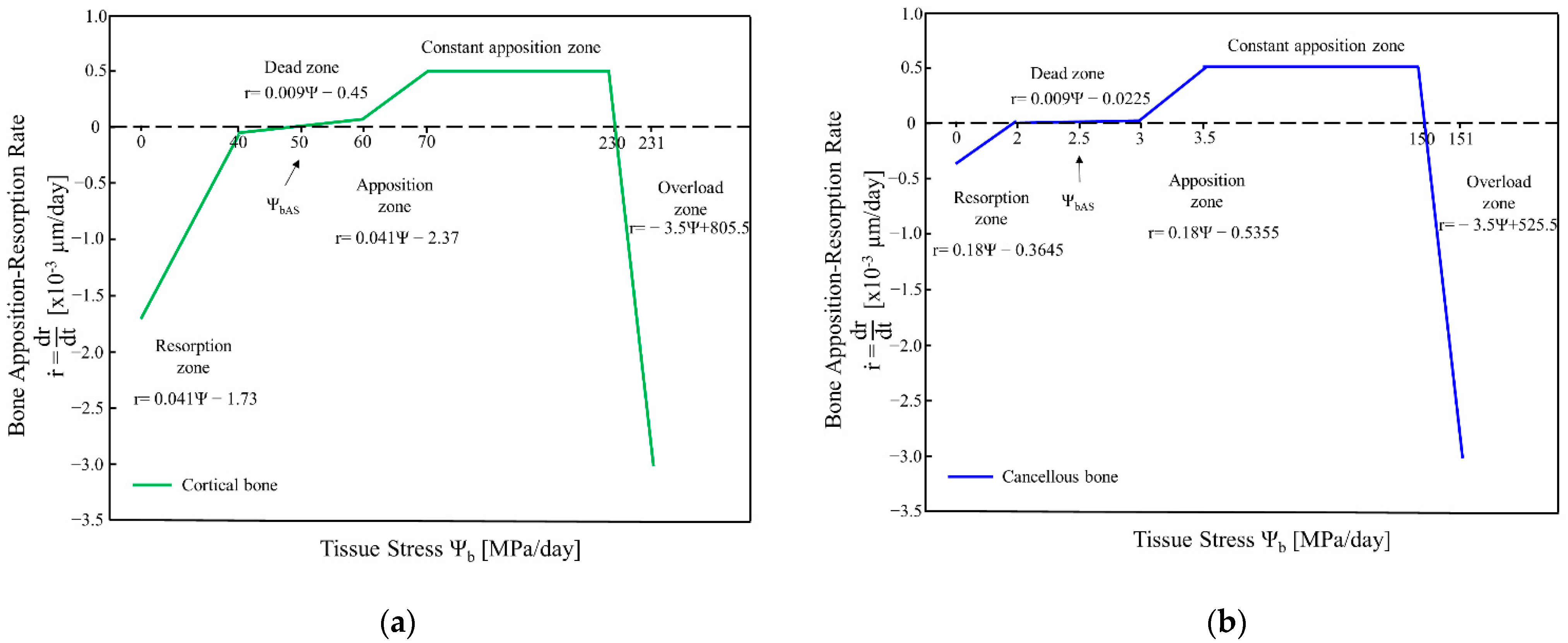
2. Bone Remodelling Algorithm

The algorithm created by the authors is based on a numerical procedure able to predict the external and internal bone remodelling process for bone tissues near an implanted prosthesis. The time-dependent bone remodelling theory of Beauprè et al. [37] is based on the concept that bone remodels itself as a response to daily loads. Bone presents a proper level of mechanical stress needed for its maintenance, called attractor state stress stimulus, ΨbAS. If the bone receives an excessive mechanical stimulation compared to the reference stimulus, new tissue will be deposited; on the other hand, if the mechanical stimulus is below the attractor state, the bone will reabsorb. According to Beauprè, the rate of bone apposition/resorption can be affected by a patient’s biological limit, such as genotype, adjacent tissue interaction, age, hormones, drugs and disease. In particular, for a decreasing stress stimulus, the resorption rate can be limited by the osteoclastic speed [38,39]. The stress stimulus for an elementary part of bone tissue can be expressed by Equation (1), where the applied load history could be decomposed in several N loads, each one characterized by a number of cycles ni of applications and a stress correlated with the strain energy density U.
Ψ b = ( ρ c ρ ) 2 [ i = 1 N n i ( 2 EU ) m ] 1 m
In this equation, ρc is the maximum cortical bone density, ρ is the apparent bone density, and E the average elastic modulus. The term m is the stress exponent, an empirical constant that can be assumed as a weighting factor for the possible differences in the relative importance of the stress magnitude and number of load cycles. The strain energy density U = ½ σε is evaluated considering a homogenized continuous media, regardless of the pores and vacuoles typical of bone structure, with σ and ε the mechanical stress and strain, respectively. In the present algorithm, only one load type is considered (N = 1), with a number of cycle per day n = 1800 [40], and the stress exponent m = 4 is adopted [41,42]. This value is the best estimate from a least-squares fit of experimental data that minimize the residual standard deviation of a bone under normal activity [43], regardless of the several eating habits of different population groups [44].
The apposition and reabsorption process of bone tissue could be expressed by a linear relation between the adaptation velocity r ˙ and an error function obtained as the difference of the actual stress stimulus and the attractor state stress stimulus for the bone (e = Ψb − ΨbAS). The attractor state stress stimulus may depend on local tissue interactions, genotype and metabolic status, but for sake of simplicity, here it is assumed to be independent of the previous effects. The error signal is followed by several tissue transducers which modify the recruitment rate and the activity of osteoblast and osteoclast, hence affecting the bone apposition or reabsorption process. Taking into account the literature data reported by Lin [44,45,46], the slope and the intercept, as well as the lower and upper bound for each stress stimulus area can be defined for cortical and cancellous bone (Figure 1). For low stress stimulus values, the bone is reabsorbed (resorption zone), while when the stress stimulus is approximately equal to the attractor state (50 MPa/day, as reported [41]), there is an equilibrium condition (dead zone), i.e., only a minimum amount of bone is deposited or removed. For high stress stimulus values (constant apposition zone), the bone is deposited as long as a limit value is reached, then the bone is reabsorbed (overload zone). Experimental analysis confirmed that this phenomenon takes place around an oral implant when the load is excessive [47,48,49]. The overload stress was evaluated by Crupi et al. [50] adopting the Taylor theory, as the stress value above which there is an unstable propagation of the crack under cyclic loading within the bone (35 MPa, with a corresponding mechanical stimulus of overload equal to 230 MPa/day) [51,52].
For internal bone remodelling, the change in density is described by a first-order linear differential equation (Equation (2)).
ρ ˙ = k r r ˙ S v ( ρ ) ρ t 0 ρ ρ c
with r ˙ being the bone apposition/resorption rate, ρt the fully mineralized tissue density, kr the active bone surface constant (assumed equal to 0.2 [53]), and Sv(ρ) the bone surface area density, defined as the amount of bone surface area in a given bone sample divided by the bulk volume (full and empty spaces). The relationship between the bone surface area density and porosity was experimentally retrieved by Martin [54], with porosity expressed as a function of the bone apparent density (Equation (3)).
S v ( ρ ) = 32.3 p 93.9 p 2 + 134 p 3 101 p 4 + 28.8 p 5   with   p = ρ t ρ ρ t
To solve the differential equation, the Euler method was implemented: the new density for each integration step was obtained as (Equation (4)).
ρ n = ρ n 1 + ρ t Δ t
The integration step adopted in the literature is of about 10–30 days [50]. In the presented model, a daily integration step was adopted to obtain more accurate results, considering that the finite element analysis was performed for every new set of material and geometrical properties. The new obtained density was compared with the minimum and maximum allowable values for the bone (cortical bone 1.74 ÷ 2 g/cm3, cancellous bone 0.9 ÷ 1.2 g/cm3 [46]) and assumed equal to the lower or upper bound if it was out of range. The bone elastic properties could be related to its apparent density, that could be deduced from CT scan [55]. In the literature, the mechanical behaviour of bone was characterized both in the axial and in the transverse direction, but it was not possible to assess a predominant orientation. For this reason, cortical bone could be assumed to follow an orthotropic behavior [56,57,58,59], while cancellous bone could be assumed to be isotropic [60,61,62]. The relationship between the elastic modulus (in MPa) and the apparent density (in g/cm3) of cancellous bone could be modelled with the power law of Equation (5), where a = 2349, and b = 2.15 for mesio-distal bone [63], while for cortical bone Equation (6) can be used [64]:
E = a ρ b
E 1 = 6.382 + 0.255 ( 23.93 + 24 ρ ) ; E 2 = 13.05 + 13 ρ ; E 3 = 23.93 + 24 ρ
In order to assess the relationship between the elastic properties of cortical bone and its apparent density, the work of Jacobs et al. [65] was considered. Mechanical stress on bone microstructure not only affects the apparent density, but also leads to a reorientation of the trabeculae, which macroscopically affects the bone stiffness tensor [C], composed of 21 independent elastic constants. For an orthotropic material, the apparent density could not be directly related to the elastic properties; therefore, Jacobs developed a theoretical model based on the optimization of the stiffness tensor. For each iteration, the stiffness tensor could be obtained as the sum of the previous value and an increment quantity ΔC (Equation (7)):
[ C ] n = [ C ] n 1 + [ Δ C ] [ Δ C ] = b ρ t σ 2 2 ρ | U |
with b being the exponent of the isotropic material model (Equation (5)), σ the average equivalent Von Mises stress, and U the strain energy density.
Once the stiffness tensors in known, the elastic properties (Young Modulus Eij and Poisson ratio νij) for cortical bone could be retrieved from Equation (7), solving the linear system:
c 11 = E 11 1 ν 12 ν 21
c 22 = E 22 1 ν 12 ν 21
c 12 = E 11 ν 12 1 ν 12 ν 21 = E 22 ν 21 1 ν 12 ν 21
c 66 = G 12
The presented algorithm can be implemented in an iterative way. For every time step, the bone stress state could be retrieved from a finite element model of the prosthetic system, evaluating the bone apposition–resorption rate from the remodelling curve (Figure 1); hence, new density values and elastic properties could be evaluated by means of Equations (3) and (4). The initial finite element model was updated considering the new calculated bone geometry due to external bone remodelling; the material properties were also updated due to internal bone remodelling.

3. Materials and Methods

Some simplifications regarding the applied loads, geometry, materials and boundary conditions of the prosthesis–bone system were adopted. A series of 2D elastic finite element analyses was conducted adopting Ansys® APDL, while Matlab® was adopted for the implementation of the bone remodelling algorithm. The prosthesis–bone system was modelled by adopting a square of D4 bone type, with external dimensions of 20 mm × 25 mm and cortical bone thickness of 1.4 mm (Figure 2). In order to simulate external bone remodelling, the upper line of the bone square was discretized with 16 segments, which were able to change their position during the simulation process to account for deposition or removal of bone tissue. This kind of solution works at the geometry level and is independent of the adopted mesh.
Internal bone remodelling was simulated by changing the material properties of each bone finite element. Table 1 reports the initial values of bone density and of the elastic constants (Young’s Moduli E, Shear Moduli G and Poisson’s ratios ν) for cortical bone, modelled as an orthotropic material [66], and for the cancellous bone, modelled as an isotropic material according to Equation (5). The prosthodontic devices were modelled assuming the material properties of titanium Grade IV.
The prosthodontic devices were meshed by adopting the 8-node plane element PLANE183, to better follow the geometric irregularities, with a free mesh and a maximum element size of 0.2 mm. The cortical and cancellous bones were meshed with a mapped mesh by adopting the 4-node plane element PLANE182 to reduce the calculation time. The finite element model considers that a sufficient amount of bone has been created around the fixture to make it stable (delayed loading condition). The bone–fixture interface was modelled as a “frictional” contact system, with a friction coefficient of 0.2, to simulate the osseointegration of the fixture allowing the transmission of a certain amount of shear stresses. Element type CONTA172 was adopted for the fixture, and TARGE169 element for the bone surface. The cortical–cancellous bone interface was modelled as a bonded contact. A chewing force of 100 N [67] was applied as a distributed load over the top surface of the abutment, acting on the occlusal plane. The bottom surface of the square bone system was fixed against all the possible movements (Figure 2b). The automatic execution of the finite element analysis and the bone remodelling estimation were performed several times, corresponding to the number of days. The estimation of the results was performed by averaging the daily results over a period of 1 month.
Four types of prosthetic devices from Sweden and Martina were adopted in this study (Figure 3). The Global implant consists of a conical fixture and a double octagonal internal connection. PRO-Link In-Link implant exhibits a cylindrical self-tapping geometry with an internal hexagon which prevents possible abutment rotations. This kind of implant is particularly indicated in non-parallel configurations thanks to its partial conical superior shape which can overcome the anatomical limits of insertion and removal of the abutment. The Kohno implant has a conical profile in the apical direction, convex in the coronal direction, with a superior cylindrical section. Its profile reduces bone trauma after load application, enhancing the primary stability and increasing the implant anti-rotation during the screwing procedures. The Premium implant exhibits is similar in structure to the Kohno implant but has a cylindrical shape, allowing, being equal the coronal diameter, a larger bone–implant contact surface along its body. In Table 2, the number of nodes and elements for each of the four FE models of the prosthesis–bone system are reported.

4. Results

The effects of a vertical daily load of 100 N were evaluated. All the simulations were carried out up to 18 months (540 days), and the following parameters were considered:
  • Internal remodelling through a change of density in cancellous and cortical bone;
  • External remodelling by moving the points on the external surface of cortical bone;
  • Stresses on the peri-implant and crestal areas;
  • Stability of the implants by vertical and horizontal micromovements.
In all simulations, the majority of the changes happened between the first 12 months [68]; hence, the results are presented for this period. Two regions were considered (Figure 2a): peri-implant cancellous bone, near the fixture, and crestal cortical bone, near the implant neck. The results were obtained per month, by averaging the daily results over that period.

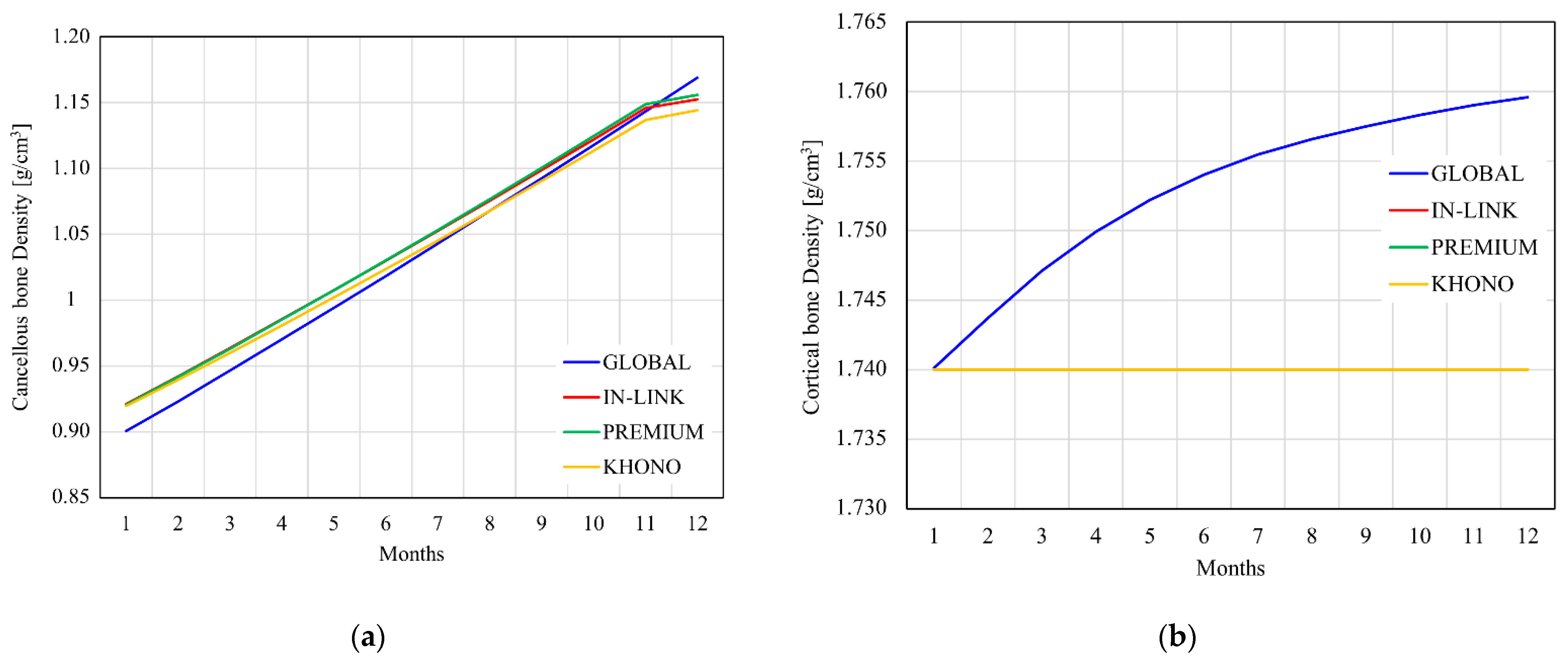
4.1. Internal Remodelling

It has been observed that the density increase is greater near the peri-implant regions compared to the regions far from the fixture, due to a higher stress concentration next to the threaded area of the fixture (Figure 4a). For all studied implant systems, a constant increment per month of 2.1% was estimated, while from the 12th month it was equal to 0.2 ÷ 0.1%. Cancellous bone density rapidly changed during the first 12 months under the action of a proper mechanical stimulus provided by the implant to the bone. As the density, and, hence the Young’s modulus, reached a certain value, the strain energy density in the peri-implant area diminished, leading to a smoother increase of the density value. Compared to cancellous tissue, the cortical bone of the crestal zone experienced a lower density increment of about 0.2% (Figure 4b). This behaviour was exhibited by all prosthetic devices, except for the Global one, which experienced a greater density increase. This can be attributed to the threaded neck of the Global implant, which was the only fixture able to stress the cortical bone of the crestal region. In fact, this region was subjected to a very low strain energy level, hence the apposition process was very slow.

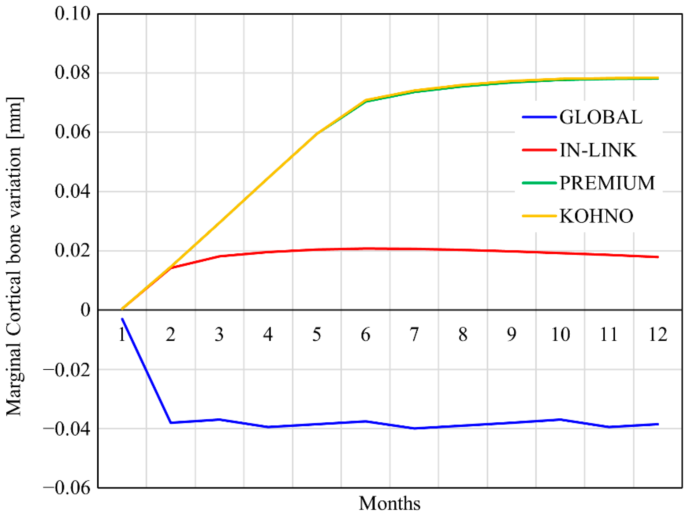
4.2. External Remodelling

The geometry of a dental implant may severely affect the apposition/resorption bone process; hence, it contributes to the clinical results and the duration over time of the prosthesis. In Figure 5, the marginal bone evolution during a period of 12 months is reported. Compared to the other implant systems, the Global system was the only one to promote a very fast bone reabsorption process during the first two months, which tended to stabilize near a value of about −0.038 mm.
This behaviour can be attributed to the presence of the threaded neck that may overstress the cortical bone, leading to the reabsorption process. On the other hand, the In-Link, Premium and Kohno implants led to the apposition of new cortical bone tissue. In particular, the In-Link implant showed a rapid stabilization from the fourth month, with an apposition of bone tissue equal to 0.019 mm. The Premium and Kohno devices showed a very similar behaviour, considering that the fixture neck region was equal for both of them. Compared to the other systems, they promoted a very high apposition process during the first six months, which led to a bone variation of about 0.078 mm in the 12th month.
Figure 6 reports the comparison between the initial crestal bone level (1st month) and the level after 12 months of simulation (12th month). It is evident that the Premium and Kohno implants determined an optimal adaptive bone remodelling near the fixture neck compared to In-Link, which only promoted peri-implant bone apposition, and to Global, which caused bone resorption both in the peri-implant region and far from the fixture.

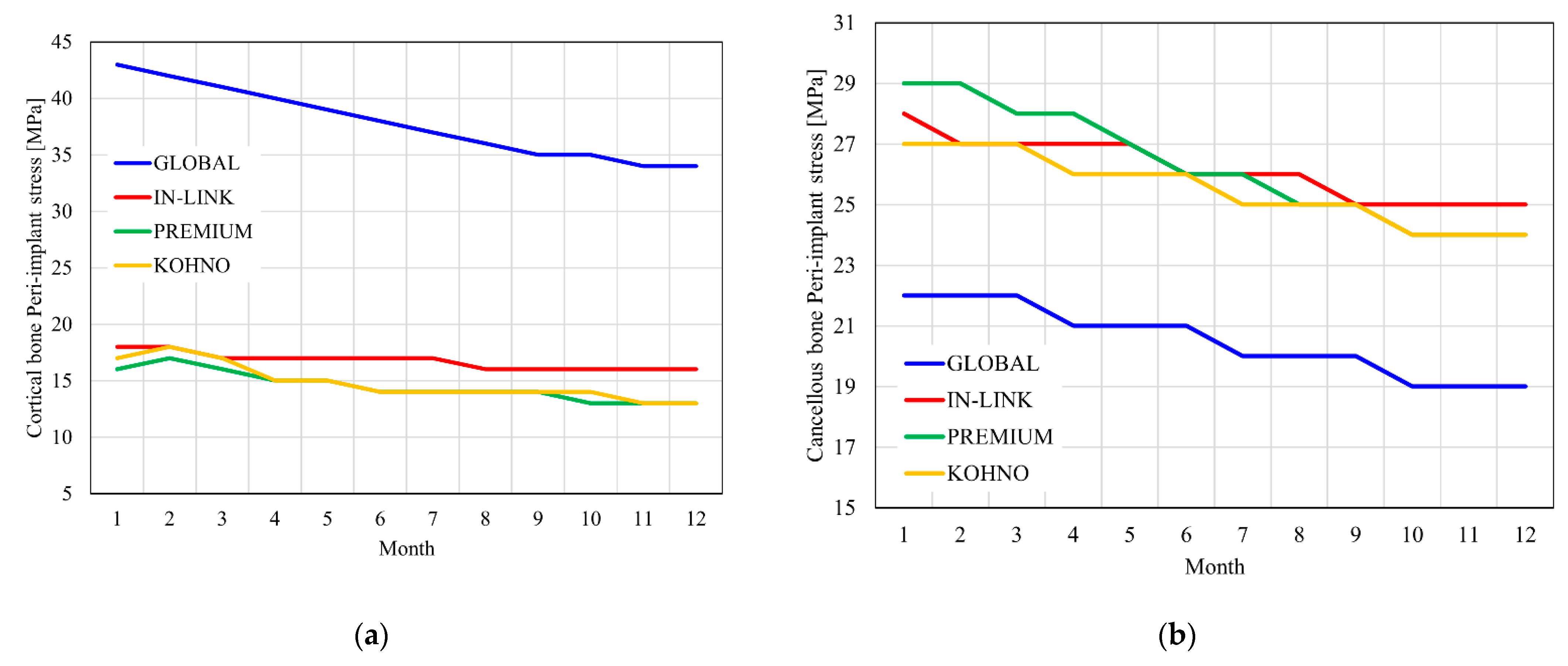
4.3. Stress on the Peri-Implant Area

The previous considerations regarding the crestal area were reflected by the stress induced in the bone by the fixtures. With regard to cortical bone (Figure 7a), the Global implant, due to its threaded neck, showed higher stress over time compared to the other implant systems, which could lead to an excessive stimulus, hence to bone reabsorption. The In-Link implant maintained a stress level over time that was slightly higher compared to that of the Premium and Kohno implants, which showed a practically equal stress trend. The cancellous bone of the peri-implant area (Figure 7b) exhibited higher stresses for the In-Link, Premium and Kohno implants, while the stress provided by the Global implant was considerably lower.
The Global implant, compared to the other ones, was not able to adequately distribute the stress in the cancellous tissue and, in addition, the excessive stress induced in the cortical bone of the crestal area led to bone reabsorption. On the other hand, the In-Link, Premium and Kohno implants stimulated in a proper way the bone tissue, ensuring internal remodelling.

4.4. Stability of the Implants

Stability was assessed by measuring the static displacement of the nodes on the upper end of the fixture after applying a vertical load. The micrometric displacements were due to the shape of the implant and the type of thread. Figure 8a reports the time evolution of the vertical displacements of the four devices. They tended to reduce over time, which indicates that, thanks to bone remodelling, the stability of the implant improved. The Global fixture showed the greater vertical displacement compared to the other fixtures, with a variation of the vertical displacement, with respect to the first moth, equal to 34.3%. On the contrary, the Premium fixture had the lowest vertical displacement, with a variation of 39.4% with respect to the first month. The In-Link and Kohno implants exhibited an intermediate behaviour, with a variation of the vertical displacement, with respect to the first month, equal to 31.9% and 34.4%, respectively. When observing the horizontal displacement trends (Figure 8b), the Global implant had the higher level of micromovements compared to the other implants that displayed a similar behaviour. The Premium implant showed the greater improvement with respect to the first month regarding horizontal micromovements (79.8%), followed by In-Link (53.1%), Kohno (22.6%) and Global (10.4%) implants. At the end of the 12 months period, considering both vertical and horizontal stability, the Global implant, despite its threaded neck, had the worst stability. On the other hand, the Premium fixture showed lower vertical and horizontal displacements, which is an index of a better stability, hence, of long-term success of the implant.

5. Discussion

The long-term durability of implant-supported prosthesis depends on a favourable osseous adaptation process to maintain osseointegration and preserve the supporting bone [69]. In this study, bone remodelling was described mathematically and was numerically simulated through a series of finite element analysis. The simulations were carried out daily for a period of 18 months on four types of dental implants, applying a load intensity of 100 N. The stresses on cancellous and cortical bone in the peri-implant areas, osseointegration in terms of density and stability and, finally, superficial bone deposition in the marginal cortical bone were evaluated. All simulations reported that the greatest changes at the bone–implant interface occurred in the first 12 months during remodelling [68]. The applied occlusal forces were discharged inside the prosthetic structure towards the fixture and were finally absorbed at the bone–implant interface [70,71,72]. The mechanical stimulus given by occlusal loads caused the release of cytokines and hormones that increased bone strength through the increase in apparent bone density, bone remodelling speed and organization of the more mineralized lamellar bone [71,73]. Predictions of internal remodelling based on the change in the initial apparent density can provide explanations for how bone responds to different dimensions and geometry of implants. The transfer of the masticatory load from the implant to the bone [27] increases bone stiffness, causing an increase in the apparent density of the peri-implant cancellous bone. However, the application of great masticatory forces is associated with lower bone densities, resulting in a higher risk of implant failure [74]. Moreover, the different thread designs in the fixtures are intended to optimize the initial contact in terms of primary stability by modifying the stress patterns in the peri-implant cancellous bone [75]. The Global implant promoted greater peri-implant bone density than all other implants, while the Kohno and Premium systems induced less similar bone growth. It is well known that the geometric properties of an implant can affect bone growth, contributing to implant duration and clinical results. Both the Global and the Kohno have a conical profile; therefore, the reason for the different final densities could be the threads design of the fixtures [24].
Several studies have underlined the influence of surface roughness or micro threads of the implant collar on the resorption of marginal bone, increasing bone resistance thanks to the presence of a greater force interlocking between the implant surface and the crestal bone [76,77]. Thus, it is reasonable to expect that no cortical bone growth occurred when using the In-Link implant due to the smooth neck. In confirmation of the scientific evidence, the Global implant with a micro-threaded neck seemed to stress the cortical bone correctly, significantly increasing its apparent density even with low-intensity loads, such as 100 N. However, the machined necks of the Premium and Kohno implants did not adequately stress the growth of cortical bone density.
Since In-Link, Premium and Kohno do not adequately stress cortical bone density, marginal bone loss and implant stability problems are expected [78]. Contrary to expectations, the machined necks of the Premium and Kohno implants induced excellent marginal cortical bone growth. The In-Link system also produced modest marginal bone apposition. Despite the excellent performances in terms of density, the Global implant was the only one causing marginal bone loss. The scientific literature reports few studies regarding the influence of different implant designs on marginal bone changes [79,80,81]. However, the results presented are difficult to interpret due to the lack of data regarding changes in bone level and the use of implants that differed in both shape and surface. Therefore, the cause is to be found in the different collar designs which could cause a different stress on cortical bone [82]. In fact, the analysis of the stresses on cortical bone showed that the Global implant resulted in higher maximum stress values than the other implants studied. Marginal bone resorption, with consequent loss of crestal height around the implant, presumably occurred thanks to cortical bone overload due to the overcoming of the physical limit of bone strength. However, it has been shown that cortical bone resorption from overload can be detected when the tensile stress exceeds 100–130 MPa [83].
It is essential to evaluate how this stress difference in cortical bone affects an implant stability. The Global system is the most unstable implant among all the implant systems studied. It is possible to state that the presence of an additional thread in the collar does not improve the mechanical behaviour of an implant, even causing crestal bone resorption. The Kohno and Premium implants differ only in the macro-geometry of the fixture, and this difference was clearly highlighted by a slight reduction in stress on the peri-implant cancellous bone, influencing internal remodelling, and by a low stability of the Kohno. Ultimately, the cylindrical geometry of the fixture and the presence of a machined collar significantly improves bone remodelling after osseointegration and the long-term probability of implant success [84,85].
Though the proposed bone remodelling algorithm is able to predict an implant performance over time, some limitations are present. The specific patient’s bone biological features were not taken into account, as they are neglected in the theory of Beauprè [37]: genotype, interaction with other surrounding tissues, patient’s age and drugs. The model could be only applied for delayed loading conditions due to the different mechanical characteristics of the collagen matrix [86]. In vivo and in vitro studies must be performed in order to have a direct correlation between the simulated and the real bone behaviour. Bone quality and patient’s chewing cycle may be, in future research, integrated into the proposed algorithm. From CT scans, it is possible to retrieve information about patients’ bone density in order to obtain a custom finite element model [87,88]. Chewing cycle and relative loads may be reconstructed from the analysis of patients’ videos [89]. In this way, it will be possible to describe in a better way the operative conditions of the implant. In particular, it will be possible to predict in a very accurate way fatigue loads (i.e., load changing over time) that may act on the implant. By analysing the stresses generated in the whole implant, it is possible to design a proper geometry able to resist against fatigue fracture [90].

6. Conclusions

A bone remodelling algorithm was created and applied to several implants in order to assess the influence of the fixture geometric parameters on the mechanical behaviour of the bone–fixture system.
Internal and, for the first time, external bone remodelling, as well as the stress field and the stability of the implants were iteratively assessed by evaluating the stress distribution near the fixture. During the first year of function, the greatest changes happened between 6 and 12 months. The apparent density of cancellous bone linearly increased during the considered period, while the cortical bone density showed an almost constant value, except for the threaded neck fixture. Bone apposition is promoted by an appropriate stimulus provided by the fixture, while reabsorption is promoted by an excessive stress field. The way by which the fixture transfers the stresses to the bone is strictly related to a proper design of the thread profile (i.e., thread pitch and implant shape), which in turn, also affects implant stability. A machined neck induced excellent marginal cortical bone growth.
Numerical algorithms, such the one adopted in the present work, to predict the bone–fixture system evolution over time, with internal and external bone remodelling, can be a useful aid to clinicians to assess the long-term success of dental implants and promote a custom prosthetic rehabilitation for each patient, based on individual bone and masticatory characteristics.

Author Contributions

Conceptualization, G.R.; methodology, D.S. and F.N.; software, D.S.; validation, G.R.; formal analysis, D.S. and F.N.; investigation, F.N.; data curation, D.S. and F.N.; writing—original draft preparation, D.S. and F.N.; writing—review and editing, D.S. and F.N.; supervision, G.R. All authors have read and agreed to the published version of the manuscript.

Funding

This research received no external funding.

Institutional Review Board Statement

Not applicable.

Informed Consent Statement

Not applicable.

Conflicts of Interest

The authors declare no conflict of interest.

References

  1. Schenk, R.K.; Buser, D. Osseointegration: A reality. Periodontology 2000 1998, 17, 22–35. [Google Scholar] [CrossRef] [PubMed]
  2. Hansson, H.-A.; Albrektsson, T.; Brȧnemark, P.-I. Structural aspects of the interface between tissue and titanium implants. J. Prosthet. Dent. 1983, 50, 108–113. [Google Scholar] [CrossRef]
  3. Aukhil, I. Biology of wound healing. Periodontology 2000 2000, 22, 44–50. [Google Scholar] [CrossRef]
  4. Albrektsson, T.; Zarb, G.; Worthington, P.; Eriksson, A.R. The long-term efficacy of currently used dental implants: A review and proposed criteria of success. Int. J. Oral Maxillofac. Implant. 1986, 1, 11–25. [Google Scholar]
  5. Albrektsson, T.; Zarb, G.A. Current interpretations of the osseointegrated response: Clinical significance. Int. J. Prosthodont. 1993, 6, 95–105. [Google Scholar]
  6. Albrektsson, T.; Chrcanovic, B.; Östman, P.-O.; Sennerby, L. Initial and long-term crestal bone responses to modern dental implants. Periodontology 2000 2016, 73, 41–50. [Google Scholar] [CrossRef] [PubMed]
  7. Herrmann, I.; Lekholm, U.; Holm, S.; Kultje, C. Evaluation of patient and implant characteristics as potential prognostic factors for oral implant failures. Int. J. Oral Maxillofac. Implant. 2005, 20, 220–230. [Google Scholar]
  8. Marquezan, M.; Osório, A.; Sant’Anna, E.; Souza, M.M.; Maia, L. Does bone mineral density influence the primary stability of dental implants? A systematic review. Clin. Oral Implant. Res. 2011, 23, 767–774. [Google Scholar] [CrossRef]
  9. Jeong, K.-I.; Kim, S.-G.; Oh, J.-S.; Jeong, M.-A. Consideration of Various Bone Quality Evaluation Methods. Implant. Dent. 2013, 22, 55–59. [Google Scholar] [CrossRef] [PubMed]
  10. Ribeiro-Rotta, R.F.; De Oliveira, R.C.G.; Dias, D.R.; Lindh, C.; Leles, C.R. Bone tissue microarchitectural characteristics at dental implant sites part 2: Correlation with bone classification and primary stability. Clin. Oral Implant. Res. 2012, 25, e47–e53. [Google Scholar] [CrossRef]
  11. Froum, S.J.; Rosen, P.S.; Clem, D.S., III. Response to ‘on crestal/marginal bone loss around dental implants’. Int. J. Periodontics Restor. Dent. 2013, 33, 407–409. [Google Scholar]
  12. Hof, M.; Pommer, B.; Zukic, N.; Vasak, C.; Lorenzoni, M.; Zechner, W. Influence of Prosthetic Parameters on Peri-Implant Bone Resorption in the First Year of Loading: A Multi-Factorial Analysis. Clin. Implant. Dent. Relat. Res. 2013, 17, e183–e191. [Google Scholar] [CrossRef] [PubMed]
  13. Wolf, J. The Law of Bone Remodeling; Springer: Berlin/Heidelberg, Germany; New York, NY, USA, 1986; pp. 63–65. [Google Scholar]
  14. Brunski, J.B. In Vivo Bone Response to Biomechanical Loading at the Bone/Dental-Implant Interface. Adv. Dent. Res. 1999, 13, 99–119. [Google Scholar] [CrossRef]
  15. Hansson, S.; Werke, M. The implant thread as a retention element in cortical bone: The effect of thread size and thread profile: A finite element study. J. Biomech. 2003, 36, 1247–1258. [Google Scholar] [CrossRef]
  16. Ormianer, Z.; Matalon, S.; Block, J.; Kohen, J. Dental Implant Thread Design and the Consequences on Long-Term Marginal Bone Loss. Implant. Dent. 2016, 25, 471–477. [Google Scholar] [CrossRef] [Green Version]
  17. Spies, B.C.; Bateli, M.; Ben Rahal, G.; Christmann, M.; Vach, K.; Kohal, R. Does Oral Implant Design Affect Marginal Bone Loss? Results of a Parallel-Group Randomized Controlled Equivalence Trial. BioMed Res. Int. 2018, 2018, 1–11. [Google Scholar] [CrossRef] [PubMed] [Green Version]
  18. De Andrade, C.L.; Carvalho, M.A.; Bordin, D.; da Silva, W.J.; Del Bel Cury, A.A.; Sotto-Maior, B.S. Biomechanical Behavior of the Dental Implant Macrodesign. Int. J. Oral Maxillofac. Implants 2017, 32, 264–270. [Google Scholar] [CrossRef] [PubMed] [Green Version]
  19. Desai, S.R.; Desai, M.S.; Katti, G.; Karthikeyan, I. Evaluation of design parameters of eight dental implant designs: A two-dimensional finite element analysis. Niger. J. Clin. Pract. 2012, 15, 176–181. [Google Scholar] [CrossRef]
  20. Aparna, I.N.; Dhanasekar, B.; Lingeshwar, D.; Gupta, L. Implant crest module: A review of biomechanical considerations. Indian J. Dent. Res. 2012, 23, 257. [Google Scholar]
  21. Lee, D.W.; Kim, N.H.; Lee, Y.; Oh, Y.A.; Lee, J.H.; You, H.K. Implant fracture failure rate and potential associated risk indicators: An up to 12-year retrospective study of implants in 5124 patients. Clin. Oral Implant. Res. 2019, 30, 206–221. [Google Scholar] [CrossRef]
  22. Peñarrocha, M.; Palomar, M.; Sanchis, J.M.; Guarinos, J.; Balaguer, J. Radiologic study of marginal bone loss around 108 dental implants and its relationship to smoking, implant location, and morphology. Int. J. Oral Maxillofac. Implant. 2004, 19, 861–867. [Google Scholar]
  23. Prosper, L.; Redaelli, S.; Pasi, M.; Zarone, F.; Radaelli, G.; Gherlone, E.F. A randomized prospective multicenter trial evaluating the platform-switching technique for the prevention of postrestorative crestal bone loss. Int. J. Oral Maxillofac. Implant. 2009, 24, 24. [Google Scholar]
  24. Cicciù, M.; Cervino, G.; Terranova, A.; Risitano, G.; Raffaele, M.; Cucinotta, F.; Santonocito, D.; Fiorillo, L. Prosthetic and Mechanical Parameters of the Facial Bone under the Load of Different Dental Implant Shapes: A Parametric Study. Prosthesis 2019, 1, 41–53. [Google Scholar] [CrossRef] [Green Version]
  25. Bozkaya, D.; Muftu, S.; Muftu, A. Evaluation of load transfer characteristics of five different implants in compact bone at different load levels by finite elements analysis. J. Prosthet. Dent. 2004, 92, 523–530. [Google Scholar] [CrossRef] [PubMed]
  26. Bramanti, E.; Cervino, G.; Lauritano, F.; Fiorillo, L.; D’Amico, C.; Sambataro, S.; Denaro, D.; Famà, F.; Ierardo, G.; Polimeni, A.; et al. FEM and Von Mises Analysis on Prosthetic Crowns Structural Elements: Evaluation of Different Applied Materials. Sci. World J. 2017, 2017, 1–7. [Google Scholar] [CrossRef] [Green Version]
  27. Cervino, G.; Romeo, U.; Lauritano, F.; Bramanti, E.; Fiorillo, L.; D’Amico, C.; Milone, D.; Laino, L.; Campolongo, F.; Rapisarda, S.; et al. Fem and Von Mises Analysis of OSSTEM® Dental Implant Structural Components: Evaluation of Different Direction Dynamic Loads. Open Dent. J. 2018, 12, 219–229. [Google Scholar] [CrossRef] [PubMed] [Green Version]
  28. Cicciù, M.; Cervino, G.; Milone, D.; Risitano, G. FEM Analysis of Dental Implant-Abutment Interface Overdenture Components and Parametric Evaluation of Equator® and Locator® Prosthodontics Attachments. Materials 2019, 12, 592. [Google Scholar] [CrossRef] [PubMed] [Green Version]
  29. Cicciu, M.; Bramanti, E.; Matacena, G.; Guglielmino, E.; Risitano, G. FEM evaluation of cemented-retained versus screw-retained dental implant single-tooth crown prosthesis. Int. J. Clin. Exp. Med. 2014, 7, 817–825. [Google Scholar]
  30. McNamara, L.; Prendergast, P.J. Bone remodelling algorithms incorporating both strain and microdamage stimuli. J. Biomech. 2007, 40, 1381–1391. [Google Scholar] [CrossRef]
  31. Dávila, E.; Ortiz-Hernández, M.; Perez, R.A.; Herrero-Climent, M.; Cerrolaza, M.; Gil, F.J. Crestal module design optimization of dental implants: Finite element analysis and in vivo studies. J. Mater. Sci. Mater. Med. 2019, 30, 90. [Google Scholar] [CrossRef]
  32. Matsuzaki, T.; Ayukawa, Y.; Matsushita, Y.; Sakai, N.; Matsuzaki, M.; Masuzaki, T.; Haraguchi, T.; Ogino, Y.; Koyano, K. Effect of post-osseointegration loading magnitude on the dynamics of peri-implant bone: A finite element analysis and in vivo study. J. Prosthodont. Res. 2019, 63, 453–459. [Google Scholar] [CrossRef]
  33. Han, J.; Sun, Y.; Wang, C. Effect of Integration Patterns Around Implant Neck on Stress Distribution in Peri-Implant Bone: A Finite Element Analysis. J. Prosthodont. 2016, 26, 549–558. [Google Scholar] [CrossRef]
  34. Wang, C.; Qing, L.; Colin, M.; Yubo, F. Numerical simulation of dental bone remodeling induced by implant-supported fixed partial denture with or without cantilever extension. Int. J. Numer. Methods Eng. 2013, 29, 1134–1147. [Google Scholar] [CrossRef]
  35. Sotto-Maior, B.S.; Mercuri, E.G.F.; Senna, P.M.; Assis, N.M.S.P.; Francischone, C.E.; Cury, A.A.D.B. Evaluation of bone remodeling around single dental implants of different lengths: A mechanobiological numerical simulation and validation using clinical data. Comput. Methods Biomech. Biomed. Eng. 2015, 19, 1–8. [Google Scholar] [CrossRef] [PubMed]
  36. Nuţu, E. Role of initial density distribution in simulations of bone remodeling around dental implants. Acta Bioeng. Biomech. 2018, 20, 23–31. [Google Scholar]
  37. Beaupre, G.S.; Orr, T.E.; Carter, D.R. An approach for time-dependent bone modeling and remodeling-theoretical development. J. Orthop. Res. 1990, 8, 651–661. [Google Scholar] [CrossRef] [PubMed]
  38. Ishijima, M.; Rittling, S.R.; Yamashita, T.; Tsuji, K.; Kurosawa, H.; Nifuji, A.; Denhardt, D.T.; Noda, M. Enhancement of osteoclastic bone resorption and suppression of osteoblastic bone formation in response to reduced mechanical stress do not occur in the absence of osteopontin. J. Exp. Med. 2001, 193, 399–404. [Google Scholar] [CrossRef] [PubMed] [Green Version]
  39. Bikle, D.D.; Halloran, B.P. The response of bone to unloading. J. Bone Miner. Metab. 1999, 17, 233–244. [Google Scholar] [CrossRef]
  40. Graf, H.; Zander, H.A. Tooth contact patterns in mastication. J. Prosthet. Dent. 1963, 13, 1055–1066. [Google Scholar] [CrossRef]
  41. Beaupre, G.S.; Orr, T.E. An approach for time-dependent bone modeling and remodeling—Application: A preliminary remodeling simulation. J. Orthop. Res. 1990, 8, 662–670. [Google Scholar] [CrossRef]
  42. Whalen, R.; Carter, D.; Steele, C. Influence of physical activity on the regulation of bone density. J. Biomech. 1988, 21, 825–837. [Google Scholar] [CrossRef]
  43. Williams, J.A.; Wagner, J.; Wasnich, R.; Heilbrun, L. The effect of long-distance running upon appendicular bone mineral content. Med. Sci. Sports Exerc. 1984, 16, 223–227. [Google Scholar] [CrossRef] [PubMed]
  44. Lin, D.; Li, Q.; Li, W.; Duckmanton, N.; Swain, M. Mandibular bone remodeling induced by dental implant. J. Biomech. 2010, 43, 287–293. [Google Scholar] [CrossRef] [PubMed]
  45. Lin, D.; Li, Q.; Li, W.; Swain, M. Bone remodeling induced by dental implants of functionally graded materials. J. Biomed. Mater. Res. Part B Appl. Biomater. 2009, 92, 430–438. [Google Scholar] [CrossRef]
  46. Lin, D.; Li, Q.; Li, W.; Swain, M. Dental implant induced bone remodeling and associated algorithms. J. Mech. Behav. Biomed. Mater. 2009, 2, 410–432. [Google Scholar] [CrossRef] [PubMed]
  47. Quirynen, M.; Naert, I.; Van Steenberghe, D.; Teerlinck, J.; DeKeyser, C.; Theuniers, G. Periodontal aspects of osseointegrated fixtures supporting an overdenture. A 4-year retrospective study. J. Clin. Periodontol. 1991, 18, 719–728. [Google Scholar] [CrossRef]
  48. Quirynen, M.; Naert, I.; Van Steenberghe, D. Fixture design and overload influence marginal bone loss and future success in the Brånemark® system. Clin. Oral Implant. Res. 1992, 3, 104–111. [Google Scholar] [CrossRef]
  49. Quirynen, M.; Naert, I.; van Steenberghe, D.; Dekeyser, C.; Callens, A. Periodontal aspects of osseointegrated fixtures supporting a partial bridge: An up to 6-years retrospective study. J. Clin. Periodontol. 1992, 19, 118–126. [Google Scholar] [CrossRef]
  50. Crupi, V.; Guglielmino, E.; La Rosa, G.; Sloten, J.V.; Van Oosterwyck, H. Numerical analysis of bone adaptation around an oral implant due to overload stress. Proc. Inst. Mech. Eng. Part H J. Eng. Med. 2004, 218, 407–415. [Google Scholar] [CrossRef]
  51. Taylor, D. Bone maintenance and remodeling: A control system based on fatigue damage. J. Orthop. Res. 1997, 15, 601–606. [Google Scholar] [CrossRef]
  52. Taylor, D.; Prendergast, P.J. A model for fatigue crack propagation and remodelling in compact bone. Proc. Inst. Mech. Eng. Part H J. Eng. Med. 1997, 211, 369–375. [Google Scholar] [CrossRef]
  53. Cowin, S.C.; Moss-Salentijn, L.; Moss, M.L. Candidates for the Mechanosensory System in Bone. J. Biomech. Eng. 1991, 113, 191–197. [Google Scholar] [CrossRef] [PubMed]
  54. Martin, R.B. Porosity and specific surface of bone. Crit. Rev. Biomed. Eng 1984, 10, 179–222. [Google Scholar] [PubMed]
  55. Park, H.-S.; Lee, Y.-J.; Jeong, S.-H.; Kwon, T.-G. Density of the alveolar and basal bones of the maxilla and the mandible. Am. J. Orthod. Dentofac. Orthop. 2008, 133, 30–37. [Google Scholar] [CrossRef]
  56. Katz, J.; Meunier, A. The elastic anisotropy of bone. J. Biomech. 1987, 20, 1063–1070. [Google Scholar] [CrossRef]
  57. Reilly, D.T.; Burstein, A.H. The elastic and ultimate properties of compact bone tissue. J. Biomech. 1975, 8, 393–405. [Google Scholar] [CrossRef]
  58. Huiskes, R. Adaptive bone-remodeling analysis. Chir. Organi Mov. 1992, 77, 121–133. [Google Scholar] [PubMed]
  59. Reilly, D.T.; Burstein, A.H.; Frankel, V.H. The elastic modulus for bone. J. Biomech. 1974, 7, 271–275. [Google Scholar] [CrossRef]
  60. Brown, T.D.; Ferguson, A.B. Mechanical Property Distributions in the Cancellous Bone of the Human Proximal Femur. Acta Orthop. Scand. 1980, 51, 429–437. [Google Scholar] [CrossRef]
  61. Martens, M.; Van Audekercke, R.; Delport, P.; De Meester, P.; Mulier, J. The mechanical characteristics of cancellous bone at the upper femoral region. J. Biomech. 1983, 16, 971–983. [Google Scholar] [CrossRef]
  62. Rohlmann, A.; Mößner, U.; Bergmann, G.; Hees, G.; Kölbel, R. Die Beanspruchung des Femur nach Hüftgelenkersatz. Z. Orthopädie Ihre Grenzgeb. 1983, 121, 47–57. [Google Scholar] [CrossRef]
  63. O’Mahony, A.M.; Williams, J.L.; Katz, J.O.; Spencer, P. Anisotropic elastic properties of cancellous bone from a human edentulous mandible. Clin. Oral Implant. Res. 2000, 11, 415–421. [Google Scholar] [CrossRef]
  64. Taber, L.A. Biomechanics of Growth, Remodeling, and Morphogenesis. Appl. Mech. Rev. 1995, 48, 487–545. [Google Scholar] [CrossRef]
  65. Jacobs, C.R.; Simo, J.C.; Beaupré, G.S.; Cartert, D.R. Adaptive bone remodeling incorporating simultaneous density and anisotropy considerations. J. Biomech. 1997, 30, 603–613. [Google Scholar] [CrossRef]
  66. Ashman, R.B.; Corint, J.D.; Turnerj, C.H. Elastic properties of cancellous bone: Measurement by an ultrasonic technique. J. Biomech. 1987, 20, 979–986. [Google Scholar] [CrossRef]
  67. Li, W.; Lin, D.; Chen, J.; Zhang, Z.; Liao, Z.; Swain, M.; Li, Q. Role of Mechanical Stimuli in Oral Implantation. J. Biosci. Med. 2014, 2, 63–68. [Google Scholar] [CrossRef] [Green Version]
  68. Isidor, F. Influence of forces on peri-implant bone. Clin. Oral Implant. Res. 2006, 17, 8–18. [Google Scholar] [CrossRef]
  69. Lee, S.-Y.; Koak, J.-Y.; Kim, S.-K.; Rhyu, I.-C.; Ku, Y.; Heo, S.-J.; Han, C.-H. A Long-Term Prospective Evaluation of Marginal Bone Level Change Around Different Implant Systems. Int. J. Oral Maxillofac. Implant. 2016, 31, 657–664. [Google Scholar] [CrossRef] [PubMed] [Green Version]
  70. Brunski, J.B.; Puleo, D.A.; Nanci, A. Biomaterials and biomechanics of oral and maxillofacial implants: Current status and future developments. Int. J. Oral Maxillofac. Implant. 2000, 15, 15. [Google Scholar]
  71. Joos, U.; Wiesmann, H.; Szuwart, T.; Meyer, U. Mineralization at the interface of implants. Int. J. Oral Maxillofac. Surg. 2006, 35, 783–790. [Google Scholar] [CrossRef] [PubMed]
  72. Michalakis, K.X.; Calvani, P.; Hirayama, H. Biomechanical considerations on tooth-implant supported fixed partial dentures. J. Dent. Biomech. 2012, 3, 1–16. [Google Scholar] [CrossRef] [PubMed]
  73. Roberts, W.E.; Turley, P.K.; Brezniak, N.; Fielder, P.J. Implants: Bone physiology and metabolism. CDA J. 1987, 15, 54–61. [Google Scholar] [PubMed]
  74. Norton, M.R.; Gamble, C. Bone classification: An objective scale of bone density using the computerized tomography scan. Clin. Oral Implant. Res. 2001, 12, 79–84. [Google Scholar] [CrossRef]
  75. Eraslan, O.; Inan, Ö. The effect of thread design on stress distribution in a solid screw implant: A 3D finite element analysis. Clin. Oral Investig. 2009, 14, 411–416. [Google Scholar] [CrossRef] [PubMed]
  76. Hansson, S. The implant neck: Smooth or provided with retention elements—A biomechanical approach. Clin. Oral Implant. Res. 1999, 10, 394–405. [Google Scholar] [CrossRef]
  77. Nickenig, H.-J.; Wichmann, M.; Schlegel, K.A.; Nkenke, E.; Eitner, S. Radiographic evaluation of marginal bone levels adjacent to parallel-screw cylinder machined-neck implants and rough-surfaced microthreaded implants using digitized panoramic radiographs. Clin. Oral Implant. Res. 2009, 20, 550–554. [Google Scholar] [CrossRef]
  78. Zhang, Q.; Yue, X. Marginal Bone Loss around Machined Smooth Neck Implants Compared to Rough Threaded Neck Implants: A Systematic Review and Meta-Analysis. J. Prosthodont. 2021, 1–11. [Google Scholar] [CrossRef]
  79. Davarpanah, M.; Martinez, H.; Tecucianu, J.F.; Alcoforado, G.; Etienne, D.; Celletti, R. The self-tapping and ICE 3i implants: A prospective 3-year multicenter evaluation. Int. J. Oral Maxillofac. Implant. 2001, 16, 52–60. [Google Scholar]
  80. Lee, D.-W.; Choi, Y.-S.; Park, K.-H.; Kim, C.-S.; Moon, I.-S. Effect of microthread on the maintenance of marginal bone level: A 3-year prospective study. Clin. Oral Implant. Res. 2007, 18, 465–470. [Google Scholar] [CrossRef]
  81. Montemezzi, P.; Ferrini, F.; Pantaleo, G.; Gherlone, E.; Capparè, P. Dental Implants with Different Neck Design: A Prospective Clinical Comparative Study with 2-Year Follow-Up. Materials 2020, 13, 1029. [Google Scholar] [CrossRef] [Green Version]
  82. Messias, A.; Nicolau, P.; Guerra, F. Titanium dental implants with different collar design and surface modifications: A systematic review on survival rates and marginal bone levels. Clin. Oral Implant. Res. 2019, 30, 20–48. [Google Scholar] [CrossRef] [Green Version]
  83. Baggi, L.; Cappelloni, I.; Di Girolamo, M.; Maceri, F.; Vairo, G. The influence of implant diameter and length on stress distribution of osseointegrated implants related to crestal bone geometry: A three-dimensional finite element analysis. J. Prosthet. Dent. 2008, 100, 422–431. [Google Scholar] [CrossRef] [Green Version]
  84. Comuzzi, L.; Tumedei, M.; Pontes, A.E.; Piattelli, A.; Iezzi, G. Primary Stability of Dental Implants in Low-Density (10 and 20 pcf) Polyurethane Foam Blocks: Conical vs Cylindrical Implants. Int. J. Environ. Res. Public Health 2020, 17, 2617. [Google Scholar] [CrossRef] [Green Version]
  85. Lovatto, S.T.; Bassani, R.; Sarkis-Onofre, R.; dos Santos, M.B.F. Influence of Different Implant Geometry in Clinical Longevity and Maintenance of Marginal Bone: A Systematic Review. J. Prosthodont. 2019, 28, e713–e721. [Google Scholar] [CrossRef] [PubMed]
  86. Cairo, F.; Barbato, L.; Tonelli, P.; Batalocco, G.; Pagavino, G.; Nieri, M. Xenogeneic collagen matrix versus connective tissue graft for buccal soft tissue augmentation at implant site. A randomized, controlled clinical trial. J. Clin. Periodontol. 2017, 44, 769–776. [Google Scholar] [CrossRef] [PubMed]
  87. Kufley, S.; Scott, J.E.; Ramirez-Yanez, G. The effect of the physical consistency of the diet on the bone quality of the mandibular condyle in rats. Arch. Oral Biol. 2017, 77, 23–26. [Google Scholar] [CrossRef] [PubMed]
  88. Ibrahim, N.; Parsa, A.; Hassan, B.; van der Stelt, P.; Rahmat, R.A.; Ismail, S.M.; Aartman, I.H.A. Comparison of anterior and posterior trabecular bone microstructure of human mandible using cone-beam CT and micro CT. BMC Oral Health 2021, 21, 249. [Google Scholar] [CrossRef] [PubMed]
  89. D’andrea, D.; Cucinotta, F.; Farroni, F.; Risitano, G.; Santonocito, D.; Scappaticci, L. Development of machine learning algorithms for the determination of the centre of mass. Symmetry 2021, 13, 401. [Google Scholar] [CrossRef]
  90. Armentia, M.; Abasolo, M.; Coria, I.; Albizuri, J. Fatigue Design of Dental Implant Assemblies: A Nominal Stress Approach. Metals 2020, 10, 744. [Google Scholar] [CrossRef]
Figure 1. Remodelling curve for: (a) cortical bone; (b) cancellous bone. Taken from [50].
Prosthesis 03 00016 g001
Figure 2. Finite element model: (a) Geometric discretization of the prosthesis–bone system; (b) Mesh and boundary conditions of the FE model.
Prosthesis 03 00016 g002
Figure 3. Adopted prosthetic devices: (a) Global; (b) In-Link; (c) Premium; (d) Kohno.
Prosthesis 03 00016 g003
Figure 4. Density evolution of: (a) Cancellous bone; (b) Cortical bone.
Prosthesis 03 00016 g004
Figure 5. Marginal cortical bone evolution.
Prosthesis 03 00016 g005
Figure 6. Comparison of the cortical bone apposition process for the prosthetic devices: (a) Global; (b) In-Link; (c) Premium; (d) Kohno.
Prosthesis 03 00016 g006
Figure 7. Average stress in: (a) crestal area; (b) peri-implant area.
Prosthesis 03 00016 g007
Figure 8. Stability of the implant, assessed by: (a) vertical displacement; (b) horizontal displacement of the upper node of the implant.
Prosthesis 03 00016 g008
Table 1. Material properties.
PropertiesCortical BoneCancellous BoneTitanium Grade IV
Density [g/cm3]1.740.94.51
Exx [GPa]19.41.87110
Eyy [GPa]10.8
Ezz [GPa]13.3
νxx0.4450.120.33
νyy0.309
νzz0.224
Gxx [GPa]4.12
Gyy [GPa]3.81
Gzz [GPa]4.63
Table 2. Finite element model dimensions.
GlobalIn-LinkKohnoPremium
Elements20,18719,06517,84817,930
Nodes21,08620,38918,89219,146
Publisher’s Note: MDPI stays neutral with regard to jurisdictional claims in published maps and institutional affiliations.

