Article

Finite Element Analysis of a New Dental Implant Design Optimized for the Desirable Stress Distribution in the Surrounding Bone Region

1
Private Practice INGEO, 28040 Varallo Pombia, Italy
2
Department of Biomedical, Surgical, and Dental Sciences, University of Milan, 20100 Milan, MI, Italy
3
Centro Odontoiatrico Albavilla, 22031 Albavilla, Italy
4
Private Practive, 65020 Pescara, Italy
5
Private Practice, 31030 Casier, Italy
6
Private Practice S.C.S. Scientific Counsulting Services, 31100 Treviso, Italy
7
Oral and Maxillofacial Sciences, University La Sapienza, 00100 Roma, Italy
*
Author to whom correspondence should be addressed.
Prosthesis 2020, 2(3), 225-236; https://doi.org/10.3390/prosthesis2030019
Submission received: 17 July 2020 / Revised: 14 August 2020 / Accepted: 17 August 2020 / Published: 24 August 2020

Abstract

:
Dental implant macro- and micro-shape should be designed to maximize the delivery of optimal favorable stresses in the surrounding bone region. The present study aimed to evaluate the stress distribution in cortical and cancellous bone surrounding two models of dental implants with the same diameter and length (4.0 × 11 mm) and different implant/neck design and thread patterns. Sample A was a standard cylindric implant with cylindric neck and V-shaped threads, and sample B was a new conical implant with reverse conical neck and with “nest shape” thread design, optimized for the favorable stress distribution in the peri-implant marginal bone region. Materials and methods: The three-dimensional model was composed of trabecular and cortical bone corresponding to the first premolar mandibular region. The response to static forces on the samples A and B were compared by finite element analysis (FEA) using an axial load of 100 N and an oblique load of 223.6 N (resulting from a vertical load of 100 N and a horizontal load of 200 N). Results: Both samples provided acceptable results under loadings, but the model B implant design showed lower strain values than the model A implant design, especially in cortical bone surrounding the neck region of the implant. Conclusions: Within the limitation of the present study, analyses suggest that the new dental implant design may minimize the transfer of stress to the peri-implant cortical bone.

1. Introduction

A key factor for the long-term success of a dental implant is to ensure that the implant can support loading conditions, transferring biting forces safely to the interfacial tissues [1]. Adverse occlusal forces may result in marginal bone resorption of surrounding bone [2,3]. Load transfer from implants to surrounding bone depends on variables such as implant geometry, shape and characteristics of its surface, loading conditions, and bone quality of the surrounding bone, among others [4,5,6,7,8]. In the process of designing new dental implants, a thorough understanding of implant biomechanics is crucial to reduce maximum stress values in the surrounding bone, and to minimize the risk of biologic and mechanic complications. In this respect, it is necessary to comprehend how the transfer and the distribution of biomechanical loads are influenced by the implant body geometry, thread design, platform design, abutment connection, etc. Several literature reviews have been conducted on the in vitro role of implant macro-design and threads design in attempts to define the biomechanical factors that most affect long-term implant success during anchorage in the bone [9,10,11]. However, there is a lack of data about the implant macro-design (body and neck) and threads design that can optimize the maintenance of peri-implant bone. In order to predict stress and strain within structures in a real situation, which cannot be solved by a traditional linear static model, nonlinear finite element analysis (FEA) is a mathematical model analysis that allows for evaluating, in a qualitatively detailed way, the mechanical behavior of dental implants, especially the stress distribution generated at the implant/bone interface [12]. In this study, a new type of dental implant, designed with the intention of creating stress initially at cancellous bone and to reduce the stress peaks in the surrounding upper cortical bone, was evaluated by FEA.

2. Materials and Methods

Two types of implants with the same diameter (4.0 mm) and length (11 mm), having the same surface and material feature, but being different in body geometry, collar geometry, and thread design were selected (Figure 1):
  • A control standard implant with cylindric body and neck and “V” shaped thread design (Sample A, control, Figure 1A)
  • A new conical implant with reverse conical neck and with “nest shape” thread design (Sample B, test, Figure 1B)
The sample A is a standard implant model, with a cylindric neck 2.5 mm in length, smooth/machined for a height of 0.7 mm. The rest of the body has unique thread patterns with V-shaped threads. Pitch of the V-shape is 0.6 mm and height is 0.35 mm.
The sample B has a reverse conical neck 2.5 mm in length with 1.3 mm microthreads and a tapered body with “nest shape” thread design. The “nest shape” has a height of 0.5 mm, and a trapezium shape with grooves both on the lower and upper side of the coil trapeze (Figure 2).
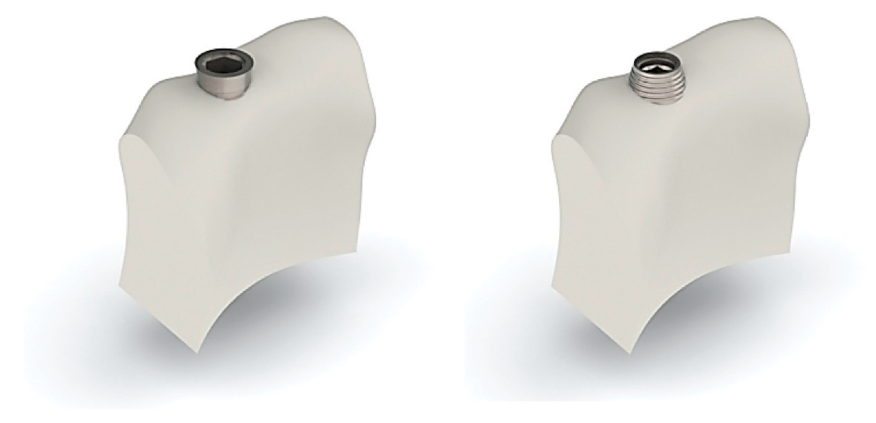
The 3D computer-aided design models of the system were built in a Solidworks 2019 SP3. The geometries were imported into the finite element software ANSYS workbench (ANSYS WB 2.0 Framework, version 12.0.1, 2009 SAS IP) in order to generate the meshes with tetrahedral solid elements. A bone block model was constructed based on a cross-sectional image of the mandibular premolar region, 17 mm in height and 12 mm in width, consisting of a cancellous bone core surrounded by a 2-mm cortical bone. The whole model is shown in Figure 3.

2.1. Material Properties

All materials were presumed to be homogenous, linearly elastic and isotropic.
The material properties, including modulus of elasticity, Poisson’s ratio and density used in the FE model, adopted from the literature [5], are listed in Table 1.
FEA: In this study, complete osseointegration between the implant and the surrounding bone was assumed. Therefore, a “fixed bond” condition was set at the interface of the bone and the implant. The same “fixed bond” condition was also set between implant–cortical-bone and implant–cancellous-bone as well as the interface between the cancellous and cortical bones. The bottom part of the mandible was considered to be fixed. Finite elements model is generated by tetrahedron and triangle shell elements and spring elements. These elements are quadratic elements which have additional nodes on the midside of the elements and volume center with nodes on the element vertices. The curved faces are represented more accurately by using quadratic elements and this representation will increase the accuracy of solution results. The accuracy will increase by generating more element and node numbers in the model, but this will also increase the solution run time and the matrices which can build impossible-to-solve mathematical models with the current hardware. The finite element result does not change much after a certain number of elements and nodes regarding the convergence studies. In this study, the finite element model is generated with the element edge lengths, which vary between 0.1 mm to 0.5 mm. The components are connected to each other by using common nodes. The internal force transfer is provided by using common nodes between contacting parts.
To determine the optimal mesh size that offered reliable results within a reasonable computational cost (<15 min), the number of elements was increased until the maximum principal stress converged. The resulting FEA model featured 78.109 four-node tetrahedron elements, 131.839 elements for implants, 13.231 elements for cortical bone, and 18.422 elements for cancellous bone.
Contact analysis defined the load and deformation transfer between different components. The friction coefficient, adopted from the literature [5] was set at 0.65 for the cortical bone–implant interface and 0.77 for the cancellous bone–implant interface. Nonlinear contact zones were defined at two critical interfaces: implant–cortical-bone and implant–cancellous-bone. Contact analysis defined the load and deformation transfer.

2.2. Boundary Conditions and Constraints

The boundary conditions applied to the FEA models were completely constrained at all directions so that neither side of the cortical or cancellous bone was rotated or moved in any direction. The model’s symmetric property allowed us to focus on half of the model for analysis, i.e., the symmetry constraints on the Z-, RX-, RY- directions.

2.3. Loading Conditions

A static load of 100 N with 0° angle and of 223.6 N (resulting from a vertical load of 100 N and a horizontal load of 200 N) with 25° angle was applied to the long axis of the implant. Deformation maps and von Mises stress maps analyses were performed in the FEA. Convergence displacement–stress U–S criteria with Newton Raphson residual control were used. Most models attained less than 0.2% convergence criteria, meaning the convergence criterion was set to less than 0.2% in the changes in the total deformation energy of all the elements. Shape control and mesh quality were measured and refined, reaching a final aspect ratio between 0.75 and 0.88. A convergence test with the finite element models was carried out to verify the quality of the mesh. The convergence criterion was set to less than 1% in the changes in the total deformation energy of all the elements. Based on the results of the convergence test, an average element size of 0.6 mm was established for the mesh in all finite element models.

2.4. FEA Data Collection

Quantitative analysis was carried out after variables were evaluated subsequent to imaginary loading. These analyses were performed at the inner implant surface. The maximum von Mises stresses (maximum equivalent stress) at the surface implant was set as output variable. Strain values were reported at the microstrain scale. For qualitative analysis, since the maximum concentrated stress and microstrain values are presented as specific numbers, a comprehensive evaluation of stress should be carried out.

3. Results

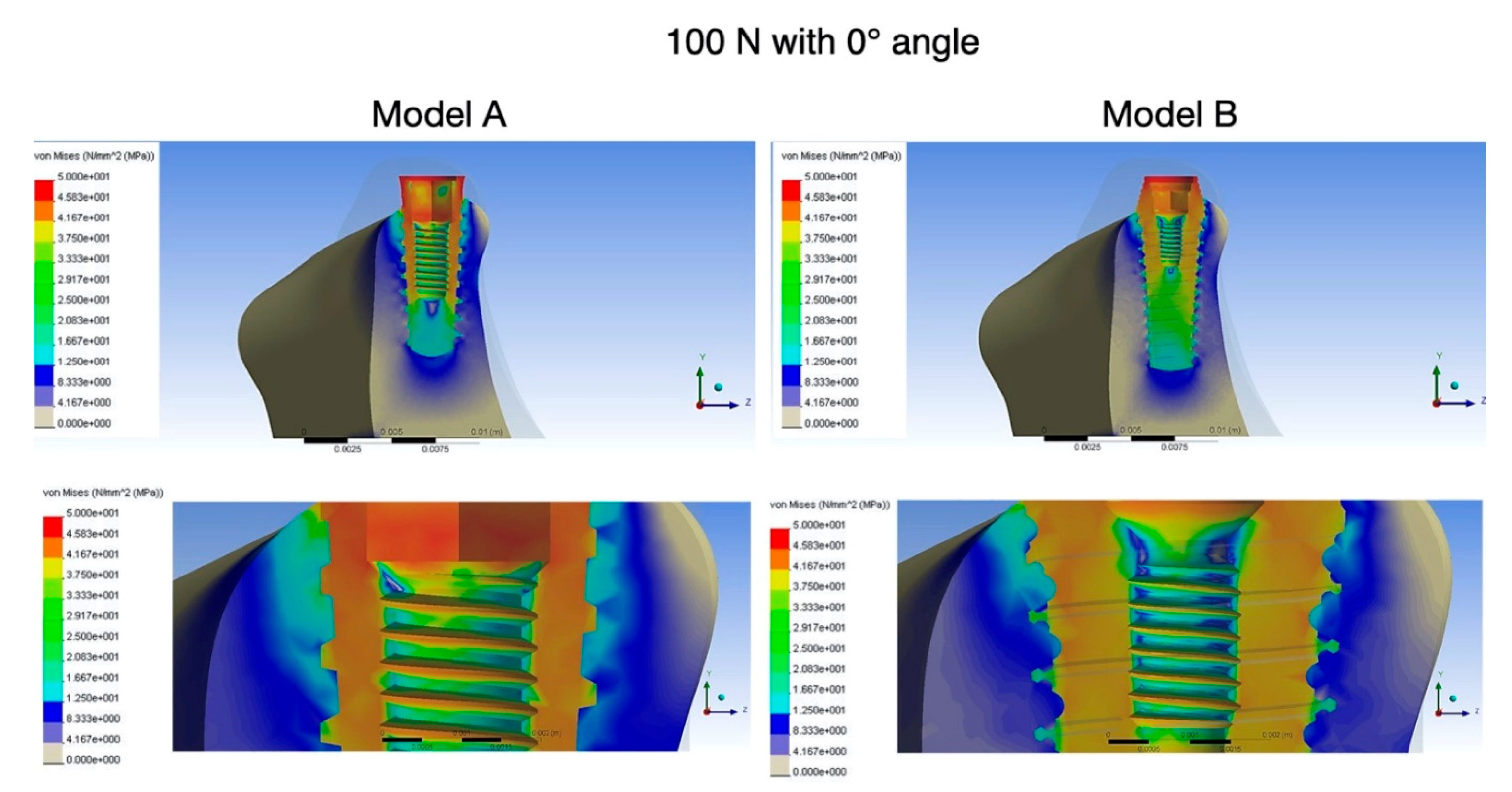
Table 2 and Table 3 report maximum values of stress distribution (von Mises) and equivalent elastic strain for different parts of the samples A and B. Figure 4 and Figure 5 show the data obtained from calculation in a stress distribution map with a color scale, which makes it possible to directly compare the stress pattern in different parts of the two samples. In both samples, maximum stresses were detected within the cortical bone surrounding the implant and within the implant neck under loading with a 0° and 25° angle. Under loading with 0°, the maximum von Mises stress values in the cortical bone for model A was 46 MPa, while for model B was 38 MPa. The maximum stress values within the cancellous bone was 29 MPa and 22 MPa for model A and for model B, respectively. Under loading with a 25°angle, the maximum von Mises stress values in the cortical bone for model A was 49 MPa, while for model B it was 41 MPa. The maximum stress values within the cancellous bone was 35 MPa and 24 MPa for model A and for model B, respectively.

4. Discussion

Dental implants consist of a combination of various design factors, including fixture shape, collar shape, thread shape and pitch, screw type, fixture connection type, etc. Each design factor has been widely investigated in previous literature [13,14,15,16,17,18]. However, when multiple design changes are made, the results derived by previous research cannot be used. To quickly analyze and predict the differences resulting from design changes in dental implant systems, the FEA is a mathematical model analysis that has been widely used in implant dentistry [12]. Therefore, this study was carried out using FEA to compare the mechanical behavior relative to design changes, including changes to implant body shape, implant collar shape, thread design and pitch, of a new dental implant design with a standard implant design with the same diameter and length. Similar to the previous literature [9,10,11], results of the current study showed that the maximum amounts of stress in both cortical and cancellous bones is concentrated around the implant neck. Therefore, in the process of designing dental implants, particular attention must be paid to the distribution of stress on the neck area of the implant. Some studies have highlighted that the implant neck designs can influence the level of stress for the peri-implant cortical bone avoiding peri-implant implant bone loss [19,20,21,22,23]. Misch and Bidez [21] reported that an implant collar angled by more than 20 degrees with a surface texture designed to increase bony contact might impose slight beneficial compressive and tensile components to the contiguous compact bone and decrease the risk of peri-implant bone loss. Mandell et al. [24] showed that orthopedic implants that have intramedullary stems with conical angles in a range of 30 to 60 degrees favor the maintenance of bone density by promoting a more stable fixation. Kitamura et al. [25] demonstrated that lower peak stresses exist in crestal compact bone contiguous to an implant that is in an oblique contact angle with the crestal compact bone to the implant neck rather than in a perpendicular angle. Misch and Bidez [21] stated that the divergent type of implant collar demonstrates a better stress distribution than a straight collar. A desire to resolve the controversial issue of which implant collar geometry is more favorable for the preservation of crestal compact bone was the motivation for the design of the new implant neck investigated in this study. Results revealed a 12% reduction of the stress peak in peri-implant cortical bone of Model B implants, compared to traditional one (Model A), demonstrating the viability of the design. The lower stress located at the cortical/cancellous boundary for the new type of implant indicated that the force was passed from below, avoiding the production of stress peak at the top of the cortical layer by directly making contact with the implant. Moreover, change of stress distribution was remarkable at the lingual side, which was closely related to the direction of the load.
The tapered root-analog design of the new implant body was suggested because it mimics the shape of natural roots, which implies favorable stress dissipation in the surrounding bone [17]. According to results to the present study, the tapered implant body (Model B) decreased stresses in both cortical and trabecular bone compared to the cylindric design (Model A). These results are in agreement with previously published data [18,19,26,27,28,29], indicating that tapered implants could reduce peak stress in both cortical and trabecular bone. Stress analysis was performed for various implant designs by Li Huang et al. [29] using three-dimensional finite element analysis approaches. Considering three cylindrical implants (without thread, with “V” thread, and with rectangular thread), two stepped implants (without thread and with “V” thread), and a tapered body implant with thread, the authors founded that the latter showed a stresses decrease of 32% in the cortical bone and 17% in the cancellous bone. The influence of the implant body design (cylindrical and tapered) on stress and strain distribution in the implant/bone interface has been also investigated by Heidari et al. [30]. Authors reported that an increase in the degree of implant taper leads to an increase in von Mises stress and strain concentration in the bone around the body of the implant, whereas at the implant neck, an increase in the degree of taper leads to a decrease of stress and strain concentration. Oliveira et al. [31], by means of a three-dimensional FEA, analyzed the influence of different implant designs on the stress and strain distribution to the implants and surrounding bone. Three implant designs with the same length and diameter were used. Compared to cylindric implants (with concave neck and convex neck), tapered implants with convex cone-shaped neck showed the most favorable design regarding stress and strain distribution to the bone and implant in most simulated situations. A previous work published by Tada et al. [32] also showed the importance of implant design on stress and strain distribution in bone around implants. The authors suggested that tapered type implants could have a favorable response compared to cylinder implants, mainly in low-density bone. Several authors have also clinically assessed the impact of implant macrodesign on the primary stability of implants [33,34]. Greater tapering of the implant body will facilitate greater implant stability, as well as a more favorable insertion, facilitating the surgical protocol [35,36]. In some specific clinical situations where greater implant stability is required (supposedly more unfavorable conditions), tapered implants show some advantages. These situations could include application of immediate loading protocols, postextraction implants, placement of implants in low-density bone, and so forth [37,38].
The current study simulated cortical and trabecular bone by using different materials. It also accounted for natural 3D geometry of the implant–bone complex. The results demonstrated that the tapered implant body of the investigated sample B, reduced stresses not only in cortical bone but also in trabecular bone. This simultaneous stress reduction in cortical and cancellous bone may be also attributed to the biomechanical effect associated with the increased depth of the thread in the model B design, which implies an increase of the interfacial area for bone–implant contact. According to in vitro results by Amid et al. [39] and in vivo results by Lee et al. [40] the presence of microthreads in the design of the Model B implant collar could also have had a positive effect in better stress distribution patterns in peri-implant cortical bone. Amid et al. [39] used FEA to investigate the influence of microthreaded implant collar design on stress distribution in the adjacent peri-implant bone. The authors reported that maximum stress values in the cortical bone surrounding the implant neck were 12 and 6.25 MPa for the microthread and conventional models, respectively. In a clinical study, Lee et al. [40] comparing 17 implants with and without microthreads on the coronal side of the fixture installed adjacent to each other within the same partially edentulous sites, observed after three years of functional loading, a decreased marginal bone loss on implants with microthreaded collar (0.24 mm vs. 0.51 mm, p < 0.001).
The thread geometry is another important factor in implant design [41,42,43]. The “V”, rectangular and buttress shapes have been the most used in implant dentistry. Depending on the configuration of thread, including shape and size (pitch and thread depth), different stresses in the bone–implant interface have been documented [41]. Initial implants introduced had the “V”-shape design. In mechanical engineering, the “V”-thread design is mainly used to improve the primary stability of the metal parts together, thanks to a better initial mechanical interlock. With the understanding of stress patterns, more and more thread geometry related designs have been investigated [34]. It has been reported that rectangular threads could transfer vertical force more evenly than “V”-threads, whereas buttress threads could combine the advantage of “V”-thread and rectangular thread designs [42]. Shear stresses are the most destructive forces on the bone–implant interface. Therefore, implant threads should be designed to minimize the amount of these adverse stresses. In addition, implant threads should allow for better stability and more implant surface contact area. Geramizadeh et al. [44], using a photoelastic stress analysis method, documented that the direction of force at the bone–implant interface is connected to the facial angle of the thread. More precisely, increasing the thread face angle increased the amount of cutting force generated. Misch et al. [23] found that both reverse buttress and rectangular threads generate lower shear force than “V” threads. Moreover, it has also been reported that “V”-shaped and buttress threads may generate forces that could lead to defect formation [45]. Implants with rectangular and buttress threads mostly dissipate axial loads through compressive force [44], while implants with “V” and reverse buttress threads transmit axial force through a combination of compressive, tensile and shear forces [23]. Findings from FEA studies in relation to the bone–implant interface, summarized in a literature review by Geng et al. [5], indicated that the rectangular thread provides an optimized surface area for intrusive compressive load transmission. Moreover, the same report highlighted that, compared to “V” shaped and reverse angle-shaped threads, rectangular-shaped threads transmit less compression and cutting-type forces to tissues. These in vitro data have been confirmed by an animal study by Steigenga et al. [46] who, comparing the removal torque values of the osseointegrated implants with rectangular, “V” shaped and reverse angled threads, reported that implants with rectangular thread shape reached the maximum torque value. In the current study, more stress distribution was measured in peri-implant cortical bone of implant model A, compared to implant model B. The reason for this could be connected with “nest shape” thread design present in implant model B. Compared to the “V” thread of implant model A, the “nest shape” increases the thread surface and depth and, consequently, increases the implant–trabecular-bone contact area. Moreover, in the “nest shape” thread, the geometric discontinuity of designs results in high stress at the valley between the thread pitches. According to what has been described as “stress shielding effect” [47], being the radius in the valley between the steps smaller than that present on the tip of the wire, the “nest-shaped” design could also determine a decrease in nonlinear stress on the surface of the thread, increasing that on the body of the implant. Therefore, on the basis of the above considerations, it is possible to speculate that the geometric discontinuity of the “nest shape” thread could improve stress distribution dissipating the stress transfer pathway from a single high-stress area into numerous disconnected areas of bone near the thread tips.
Many factors have been proposed to contribute to the marginal bone loss around a dental implant, such as, unfavorable stress distribution, surgical trauma and implant-abutment microgap with bacterial infiltration [48]. Additionally, the implant neck design and surface characterization have been associated with marginal bone loss [49]. This has led to the development of implants with a new collar shape and topographic modification in order to reduce the marginal bone loss. Currently, FEA studies designed to explore load dependent biomechanical circumstances in peri-implant tissues are abundant, but thus far, similar approaches, particularly to marginal bone loss, are scarce. The geometry of the implant–bone interface at the crestal level fosters well-defined zones of stress concentration. Therefore, it is possible to determine this by means of numerical model differences in stress concentration when applied to the same locus of the interface. In the present study, in the cortical bone surrounding the implant neck, the mean values of the maximum equivalent stress were lower in sample B than in sample A for all loading directions (axial 38 MPa vs. 46 MPa, oblique 41 MPa vs. 49 MPa). As far as the authors are aware, no FEA data are reported in the literature on the approximate threshold above which marginal bone resorption may possibly be caused/initiated, therefore it is difficult to compare outcome data of the present study with other FEA studies. However, according to the collected data, we could clearly demonstrate the superiority of model B in the reduction of stress in the peri-implant cortical bone region, since in similar lengths and diameter, the stress magnitude was consistently lower compared to model A.
The current finite elements study presents some limitations that make it impossible to simulate clinical experiments exactly. First, FEA cannot consider the influence of forces applied by the tongue and other muscles of the oral cavity and the influence of different loading conditions present during the chewing cycle. Second, the jawbone was considered to be isotropic and homogenous, and the interface between cortical/cancellous bone and between the implant and cortical/cancellous bone has been assumed completely bonded, although this is not the case in clinical conditions. Third, the occlusal forces have been applied on the implant, while, in real clinical conditions these are applied on the crown. Moreover, the abutment and its micromovements have been not considered.
Although such simplifications related to the methodology are considered to be acceptable in experimental tests, the present study cannot provide absolute and effective stress and strain values compared to a real model. Therefore, it is necessary to contrast the presented results with those obtained in in vivo studies.

5. Conclusions

In the current study, the relations between the loading force and stress on the alveolar bone surrounding two models of dental implants with same diameter and length (4.0 × 11 mm) and different implant/neck design and thread patterns were evaluated. Findings of FEA analysis showed that:
  • Maximum von Mises stresses in the peri-implant cortical bone region were lower in the new implant model B than in the conventional model A.
  • The new implant model B showed reduced stress concentration in the area of compact bone, which was shifted to the area of cancellous bone during axial and oblique load.
Therefore, within the limitations of the present study, one may conclude that the new dental implant design can contribute to the favorable stress distribution on the surrounding bone, which can affect the long term longevity of the implant.

Author Contributions

Conceptualization, L.P.; Data curation, C.B., M.R., C.V. and D.D.C.; Investigation, L.P.; Methodology, R.G.; Writing—original draft, R.G. All authors have read and agreed to the published version of the manuscript.

Funding

This research received no external funding.

Acknowledgments

The authors would like to thank the Ornaghi company (Italy), for providing implants used for the biomechanical comparison.

Conflicts of Interest

Authors reported no conflict of interest for the current study.

References

  1. Brunski, J.B. Biomechanical factors affecting the bone-dental implant interface. Clin. Mater. 1992, 10, 153–201. [Google Scholar] [CrossRef]
  2. Carter, D.; Van Der Meulen, M.; Beaupré, G.; Van Der Meulen, M.C.H. Mechanical factors in bone growth and development. Bone 1996, 18, S5–S10. [Google Scholar] [CrossRef]
  3. Quirynen, M.; Naert, I.; Van Steenberghe, D. Fixture design and overload influence marginal bone loss and future success in the BranemarkR system. Clin. Oral Implant. Res. 1992, 3, 104–111. [Google Scholar] [CrossRef] [PubMed]
  4. Holmes, D.C.; Loftus, J.T. Influence of bone quality on stress distribution for endosseous implants. J. Oral Implant. 1997, 23, 104–111. [Google Scholar]
  5. Geng, J.-P.; Tan, K.B.C.; Liu, G.-R. Application of finite element analysis in implant dentistry: A review of the literature. J. Prosthet. Dent. 2001, 85, 585–598. [Google Scholar] [CrossRef] [Green Version]
  6. Sahin, S.; Cehreli, M.C.; Yalcin, E. The influence of functional forces on the biomechanics of implant-supported prostheses—A review. J. Dent. 2002, 30, 271–282. [Google Scholar] [CrossRef]
  7. Bozkaya, D.; Müftü, S.; Muftu, A. Evaluation of load transfer characteristics of five different implants in compact bone at different load levels by finite elements analysis. J. Prosthet. Dent. 2004, 92, 523–530. [Google Scholar] [CrossRef]
  8. Eskitascioglu, G.; Usumez, A.; Sevimay, M.; Soykan, E.; Ünsal, E.; Eskitaşcıoğlu, G. The influence of occlusal loading location on stresses transferred to implant-supported prostheses and supporting bone: A three-dimensional finite element study. J. Prosthet. Dent. 2004, 91, 144–150. [Google Scholar] [CrossRef]
  9. Maminskas, J.; Puisys, A.; Kuoppala, R.; Raustia, A.; Juodžbalys, G. The Prosthetic Influence and Biomechanics on Peri-Implant Strain: A Systematic Literature Review of Finite Element Studies. J. Oral Maxillofac. Res. 2016, 7, e4. [Google Scholar] [CrossRef]
  10. Batista, V.E.; Junior, J.F.S.; Almeida, D.A.; Lopes, L.F.; Verri, F.R.; Pellizzer, E.P. The effect of offset implant configuration on bone stress distribution: A systematic review. J. Prosthodont. 2015, 24, 93–99. [Google Scholar] [CrossRef]
  11. Assunção, W.G.; Barão, V.A.R.; Tabata, L.F.; Gomes, E.A.; Delben, J.A.; Dos Santos, P. Biomechanics Studies in Dentistry. J. Craniofacial Surg. 2009, 20, 1173–1177. [Google Scholar] [CrossRef]
  12. Chang, Y.; Tambe, A.A.; Maeda, Y.; Wada, M.; Gonda, T. Finite element analysis of dental implants with validation: To what extent can we expect the model to predict biological phenomena? A literature review and proposal for classification of a validation process. Int. J. Implant. Dent. 2018, 4, 7. [Google Scholar] [CrossRef] [PubMed]
  13. Chang, P.-K.; Chen, Y.-C.; Huang, C.-C.; Lu, W.-H.; Chen, Y.-C.; Tsai, H.-H. Distribution of micromotion in implants and alveolar bone with different thread profiles in immediate loading: A finite element study. Int. J. Oral Maxillofac. Implant. 2012, 27, e96–e101. [Google Scholar]
  14. Eraslan, O.; Inan, Ö. The effect of thread design on stress distribution in a solid screw implant: A 3D finite element analysis. Clin. Oral. Investig. 2009, 14, 411–416. [Google Scholar] [CrossRef] [PubMed]
  15. Kong, L.; Liu, B.; Hu, K.-J.; Li, D.-H.; Song, Y.-L.; Ma, P.; Yang, J. Optimized thread pitch design and stress analysis of the cylinder screwed dental implant. Hua Xi Kou Qiang Yi Xue Za Zhi 2006, 24, 509–512. [Google Scholar] [PubMed]
  16. Ao, J.; Li, T.; Liu, Y.; Ding, Y.; Wu, G.; Hu, K.; Kong, L. Optimal design of thread height and width on an immediately loaded cylinder implant: A finite element analysis. Comput. Boil. Med. 2010, 40, 681–686. [Google Scholar] [CrossRef] [PubMed]
  17. Maiorana, C.; Santoro, F. Maxillary and mandibular bonereconstruction with hip grafts and implants using Frialit-2 implants. Int. J. Periodontics Restor. Dent. 2002, 22, 221–229. [Google Scholar]
  18. Yalçın, M.; Kaya, B.; Laçin, N.; Arı, E. Three-Dimensional Finite Element Analysis of the Effect of Endosteal Implants with Different Macro Designs on Stress Distribution in Different Bone Qualities. Int. J. Oral Maxillofac. Implant. 2019, 34, e43–e50. [Google Scholar] [CrossRef]
  19. Sivrikaya, E.C.; Omezli, M.M. Effect of Tapered and Cylindrical Implants on Stress Distribution in Different Bone Qualities: Finite Element Analysis. Int. J. Oral Maxillofac. Implant. 2019, 34, e99–e105. [Google Scholar] [CrossRef]
  20. Do, G.H.; Lee, S.J.; Kim, J.M.; Kim, S.M. Study on the Fatigue Test and the Accelerated Life Test for Dental Implant using Universal-Joint Test Type. J. Appl. Reliab. 2017, 17, 50–57. [Google Scholar]
  21. Oh, T.-J.; Yoon, J.; Misch, C.E.; Wang, H.-L. The Causes of Early Implant Bone Loss: Myth or Science? J. Periodontol. 2002, 73, 322–333. [Google Scholar] [CrossRef] [PubMed]
  22. Shen, W.-L.; Chen, C.-S.; Hsu, M.-L. Influence of implant collar design on stress and strain distribution in the crestal compact bone: A three-dimensional finite element analysis. Int. J. Oral Maxillofac. Implant. 2010, 25, 901–910. [Google Scholar]
  23. Misch, C.E.; Bidez, M.W.; Strong, J.T. Scientific rationale for dental implant design. In Contemporary Implant Dentistry, 3rd ed.; Misch, C.E., Ed.; Mosby: St Louis, MO, USA, 2008; pp. 200–209. [Google Scholar]
  24. Mandell, J.A.; Carter, D.R.; Goodman, S.B.; Schurman, D.J.; Beaupre, G.S. A conical-collared intramedullary stem can improve stress transfer and limit micromotion. Clin. Biomech. (Bristol, Avon) 2004, 19, 695–703. [Google Scholar] [CrossRef] [PubMed]
  25. Kitamura, E.; Stegaroiu, R.; Nomura, S.; Miyakawa, O. Biomechanical aspects of marginal bone resorption around osseointegrated implants: Considerations based on a three-dimensional finite element analysis. Clin. Oral Implant. Res. 2004, 15, 401–412. [Google Scholar] [CrossRef] [PubMed]
  26. A Atieh, M.; Alsabeeha, N.; Duncan, W. Stability of tapered and parallel-walled dental implants: A systematic review and meta-analysis. Clin. Implant. Dent. Relat. Res. 2018, 20, 634–645. [Google Scholar] [CrossRef] [PubMed]
  27. Arinc, H. Effects of Prosthetic Material and Framework Design on Stress Distribution in Dental Implants and Peripheral Bone: A Three-Dimensional Finite Element Analysis. Med. Sci. Monit. 2018, 24, 4279–4287. [Google Scholar] [CrossRef]
  28. Wilson, T.; Miller, R.; Trushkowsky, R.D.; Dard, M. Tapered Implants in Dentistry. Adv. Dent. Res. 2016, 28, 4–9. [Google Scholar] [CrossRef]
  29. Huang, H.-L.; Chang, C.-H.; Hsu, J.-T.; Fallgatter, A.M.; Ko, C.-C. Comparison of implant body designs and threaded designs of dental implants: A 3-dimensional finite element analysis. Int. J. Oral Maxillofac. Implant. 2007, 22, 551–562. [Google Scholar]
  30. Heidari, B.; Bisadi, H.; Heidari, B.; Kadkhodazadeh, M. Influence of different tapered implants on stress and strain distribution in bone and implant: A finite element analysis. J. Periodontol. Implant. Dent. 2009, 1, 11–19. [Google Scholar]
  31. Oliveira, H.; Velasco, A.B.; Rios, V.; Lasheras, F.S.; Lemos, B.F.; Gil, F.J.; Carvalho, A.; Herrero-Climent, M. Effect of Different Implant Designs on Strain and Stress Distribution under Non-Axial Loading: A Three-Dimensional Finite Element Analysis. Int. J. Environ. Res. Public Health 2020, 17, 4738. [Google Scholar] [CrossRef]
  32. Tada, S.; Stegaroiu, R.; Kitamura, E.; Miyakawa, O.; Kusakari, H. Influence of implant design and bone quality on stress/strain distribution in bone around implants: A 3-dimensional finite element analysis. Int. J. Oral Maxillofac. Implant. 2003, 18, 357–368. [Google Scholar]
  33. Karl, M.; Irastorza-Landa, A. Does implant design affect primary stability in extraction sites? Quintessence Int. 2017, 48, 219–224. [Google Scholar] [PubMed]
  34. Rios, V.; Menjívar-Galán, A.M.; Herrero-Climent, M.; Rios-Carrasco, B.; Fernández-Palacín, A.; A Perez, R.; Gil, F.J.; Herrero-Climent, M. Unravelling the effect of macro and microscopic design of dental implants on osseointegration: A randomised clinical study in minipigs. J. Mater. Sci. Mater. Electron. 2018, 29, 99. [Google Scholar] [CrossRef] [PubMed]
  35. Irinakis, T.; Wiebe, C. Initial Torque Stability of a New Bone Condensing Dental Implant. A Cohort Study of 140 Consecutively Placed Implants. J. Oral Implant. 2009, 35, 277–282. [Google Scholar] [CrossRef]
  36. O’Sullivan, D.; Sennerby, L.; Meredith, N. Influence of implant taper on the primary and secondary stability of osseointegrated titanium implants. Clin. Oral Implant. Res. 2004, 15, 474–480. [Google Scholar] [CrossRef]
  37. Kim, Y.-K.; Lee, J.-H.; Lee, J.-Y.; Yi, Y.-J. A randomized controlled clinical trial of two types of tapered implants on immediate loading in the posterior maxilla and mandible. Int. J. Oral Maxillofac. Implant. 2013, 28, 1602–1611. [Google Scholar] [CrossRef]
  38. Javed, F.; Ahmed, H.B.; Crespi, R.; Romanos, G.E. Role of primary stability for successful osseointegration of dental implants: Factors of influence and evaluation. Interv. Med. Appl. Sci. 2013, 5, 162–167. [Google Scholar] [CrossRef]
  39. Amid, R.; Raoofi, S.; Kadkhodazadeh, M.; Movahhedi, M.R.; Khademi, M. Effect of microthread design of dental implants on stress and strain patterns: A three-dimensional finite element analysis. Biomed. Tech. Eng. 2013, 58, 457–467. [Google Scholar] [CrossRef]
  40. Lee, D.-W.; Choi, Y.-S.; Park, K.-H.; Kim, C.-S.; Moon, I.-S. Effect of microthread on the maintenance of marginal bone level: A 3-year prospective study. Clin. Oral Implant. Res. 2007, 18, 465–470. [Google Scholar] [CrossRef]
  41. Alireza, M.; Alireza, Z.; Mahmoud, K. The Effect of Implant Thread Design on Stress Distribution in Anisotropic Bone with Different Osseointegration Conditions: A Finite Element Analysis. Int. J. Oral Maxillofacc. Implant. 2015, 30, 1317–1326. [Google Scholar]
  42. Abuhussein, H.; Pagni, G.; Rebaudi, A.; Wang, H.-L. The effect of thread pattern upon implant osseointegration. Clin. Oral Implant. Res. 2010, 21, 129–136. [Google Scholar] [CrossRef] [PubMed] [Green Version]
  43. Udomsawat, C.; Rungsiyakull, P.; Rungsiyakull, C.; Khongkhunthian, P. Comparative study of stress characteristics in surrounding bone during insertion of dental implants of three different thread designs: A three-dimensional dynamic finite element study. Clin. Exp. Dent. Res. 2018, 5, 26–37. [Google Scholar] [CrossRef] [PubMed]
  44. Geramizadeh, M.; Katoozian, H.; Amid, R.; Kadkhodazadeh, M. Comparison of finite element results with photoelastic stress analysis around dental implants with different threads. Dent. Med. Probl. 2018, 55, 17–22. [Google Scholar] [CrossRef] [PubMed] [Green Version]
  45. Geramizadeh, M.; Katoozian, H.; Amid, R.; Kadkhodazadeh, M. Static, Dynamic, and Fatigue Finite Element Analysis of Dental Implants with Different Thread Designs. J. Autom. Inf. Sci. 2016, 26, 347–355. [Google Scholar] [CrossRef]
  46. Steigenga, J.; Al-Shammari, K.; Misch, C.; Nociti, F.H., Jr.; Wang, H.-L. Effects of Implant Thread Geometry on Percentage of Osseointegration and Resistance to Reverse Torque in the Tibia of Rabbits. J. Periodontol. 2004, 75, 1233–1241. [Google Scholar] [CrossRef]
  47. Shirazi, H.A.; Ayatollahi, M.R.; Asnafi, A. To reduce the maximum stress and the stress shielding effect around a dental implant–bone interface using radial functionally graded biomaterials. Comput. Methods Biomech. Biomed. Eng. 2017, 14, 1–10. [Google Scholar] [CrossRef]
  48. Acharya, A.; Leung, M.C.T.; Ng, K.T.; Fan, M.H.; Fokas, G.; Mattheos, N. Peri-implant marginal bone loss rate pre- and post-loading: An exploratory analysis of associated factors. Clin. Oral Implant. Res. 2019, 30, 410–419. [Google Scholar] [CrossRef]
  49. Koodaryan, R.; Hafezeqoran, A. Evaluation of Implant Collar Surfaces for Marginal Bone Loss: A Systematic Review and Meta-Analysis. Biomed. Res. Int. 2016, 2016, 1–10. [Google Scholar] [CrossRef] [Green Version]
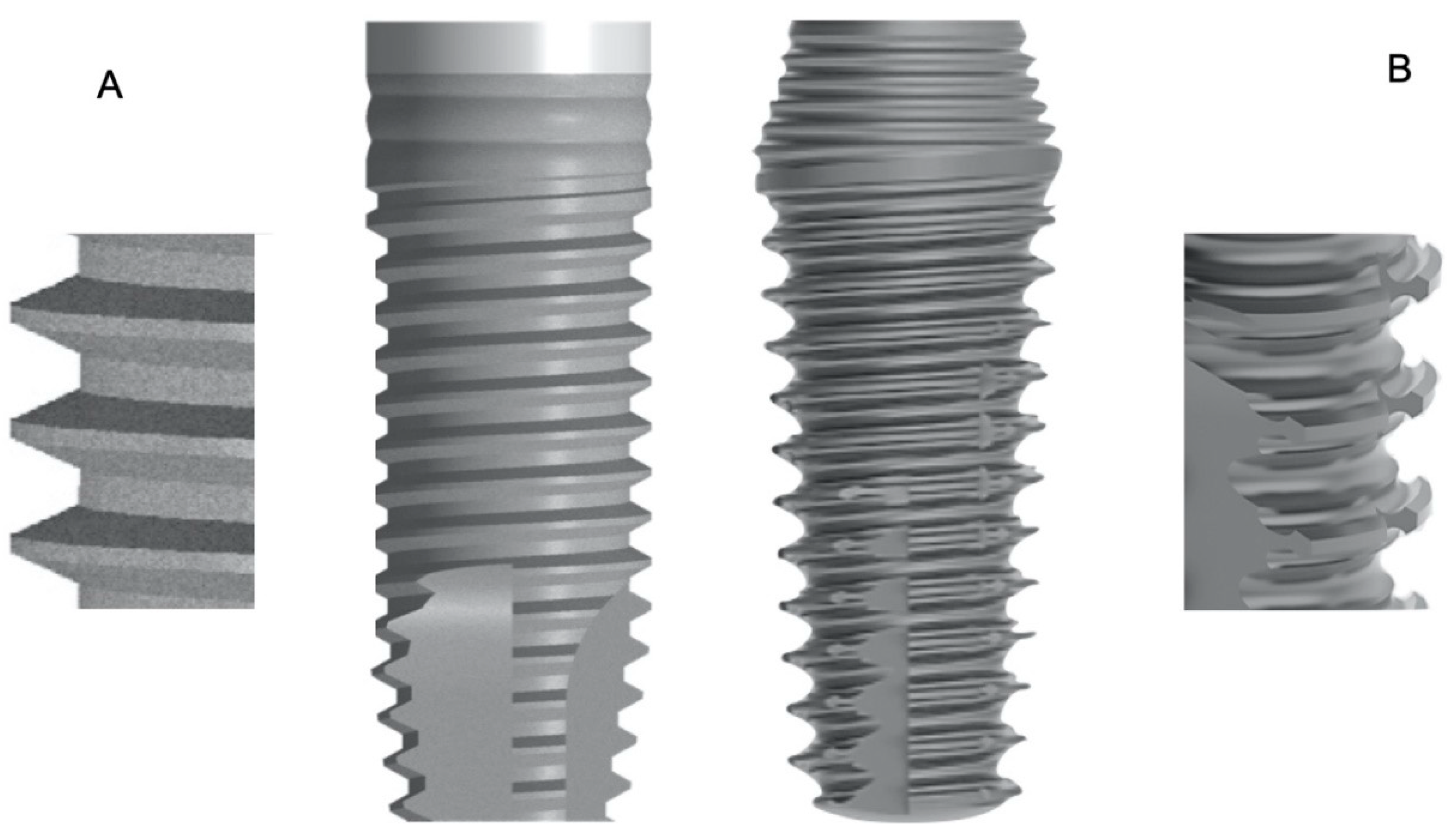
Figure 1. (A) control cylindric implant with “V” thread; (B) test new tapered implant with reverse conical collar and “nest shape” thread.
Prosthesis 02 00019 g001
Figure 2. The “nest shape” thread design of the test tapered implant with reverse conical collar.
Prosthesis 02 00019 g002
Figure 3. Whole model including implant, cortical bone, and cancellous bone.
Prosthesis 02 00019 g003
Figure 4. Stress patterns in cortical and cancellous bone with implant models A and B for vertical loading.
Prosthesis 02 00019 g004
Figure 5. Stress patterns in cortical and cancellous bone with implant models A and B for oblique loading.
Prosthesis 02 00019 g005
Table 1. Mechanical properties of the materials.
MaterialsYoung’s Modulus (MPa)Poisson’ RatioDensity (g/cm3)
Cortical Bone1.47000.31.85
Cancellous Bone14700.30.9
Titanium 0.354.5
Table 2. Model A under 100 N with 0° and 223.6 N (resulting from a vertical load of 100 N and a horizontal load of 200 N) with 25° angle.
100 N, 0° Angle223.6 N, 25° Angle
Equivalent (von Mises) stress (MPa)Equivalent elastic strain Equivalent (von Mises) stress (MPa)Equivalent elastic strain
Cortical bone 460.00157490.00349
Cancellous bone 290.00166350.00154
Table 3. Model B under 100 N with 0° and 223.6 N (resulting from a vertical load of 100 N and a horizontal load of 200 N) with 25° angle.
100 N, 0° Angle223.6 N, 25° Angle
Equivalent (von Mises) stress (MPa)Equivalent elastic strain Equivalent (von Mises) stress (MPa)Equivalent elastic strain
Cortical bone 380.0021410.0046
Cancellous bone 220.0047240.0063