
Contact Analysis of EMB Actuator Considering Assembly Errors with Varied Braking Intensities


Abstract
1. Introduction
2. Principle and Validation of EMB Actuator
2.1. Working Principle
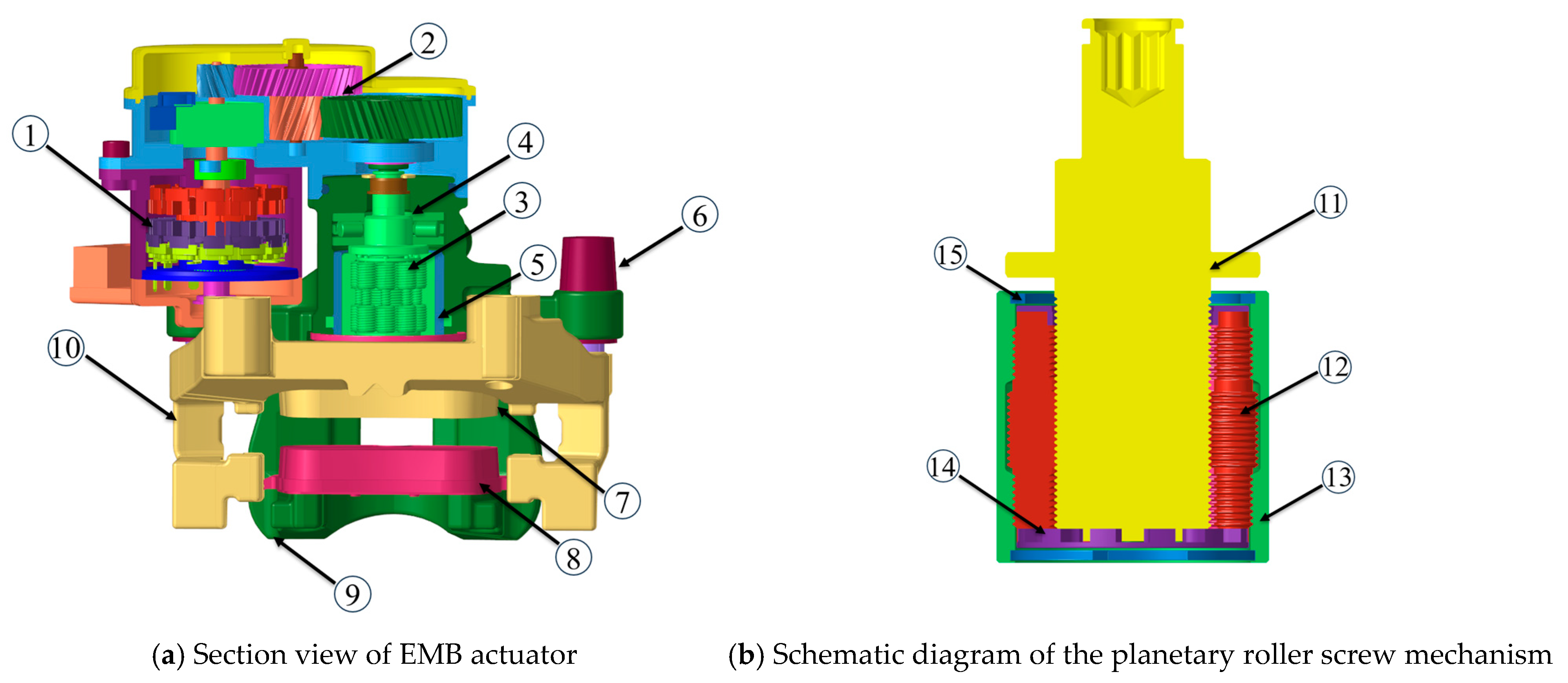
2.1.1. Composition of EMB Actuator
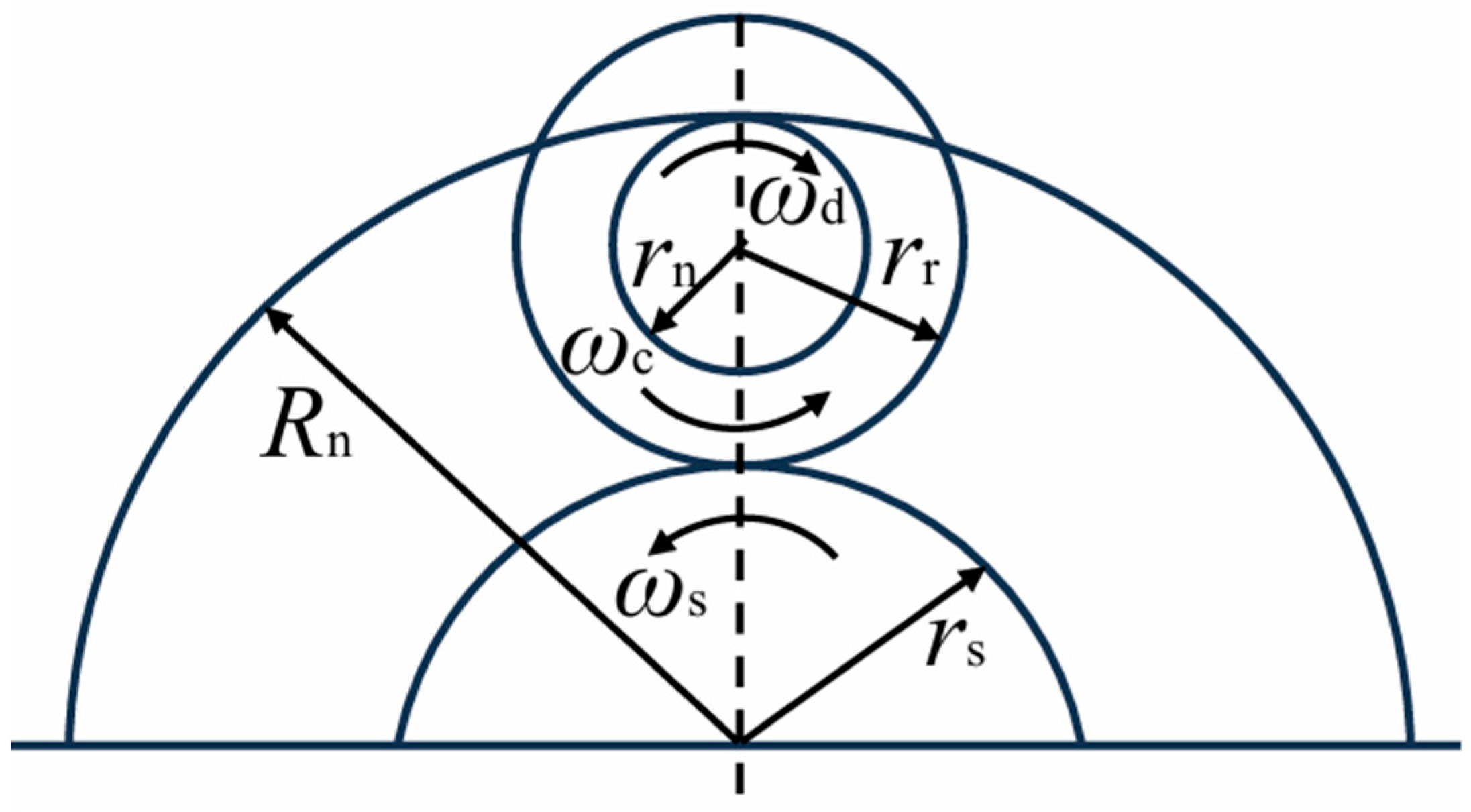
2.1.2. Kinematic Analysis of DPRS
2.1.3. Working Principle of the EMB Actuator
2.2. Design Parameters
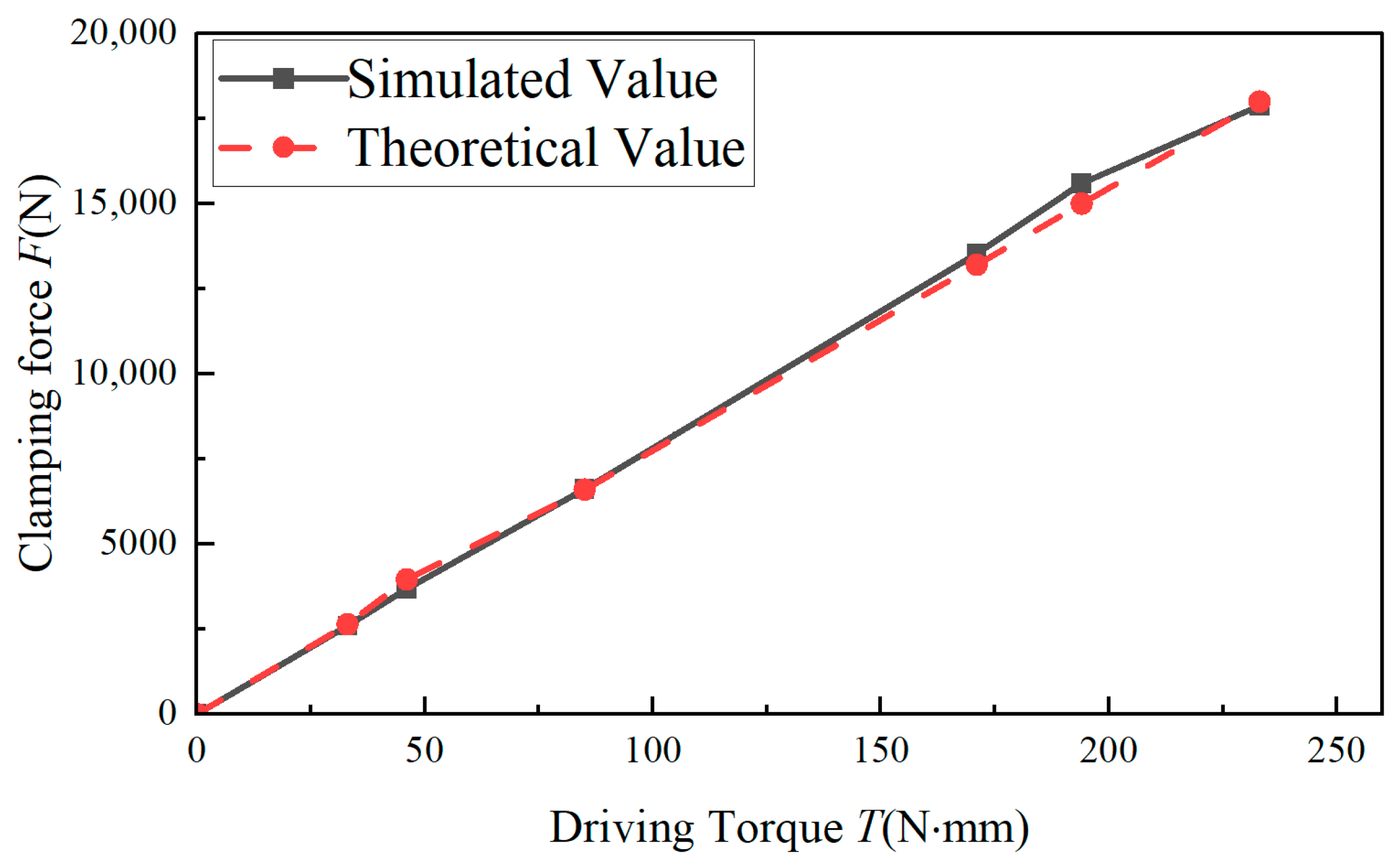
2.3. Braking Force Verification
3. Simulation of Braking Clamping Force for the Actuator
3.1. Dynamic Model
3.1.1. Application of Kinematic Pairs
3.1.2. Contact Force and Load Application
3.2. Simulation of the Brake Clearance Elimination Phase
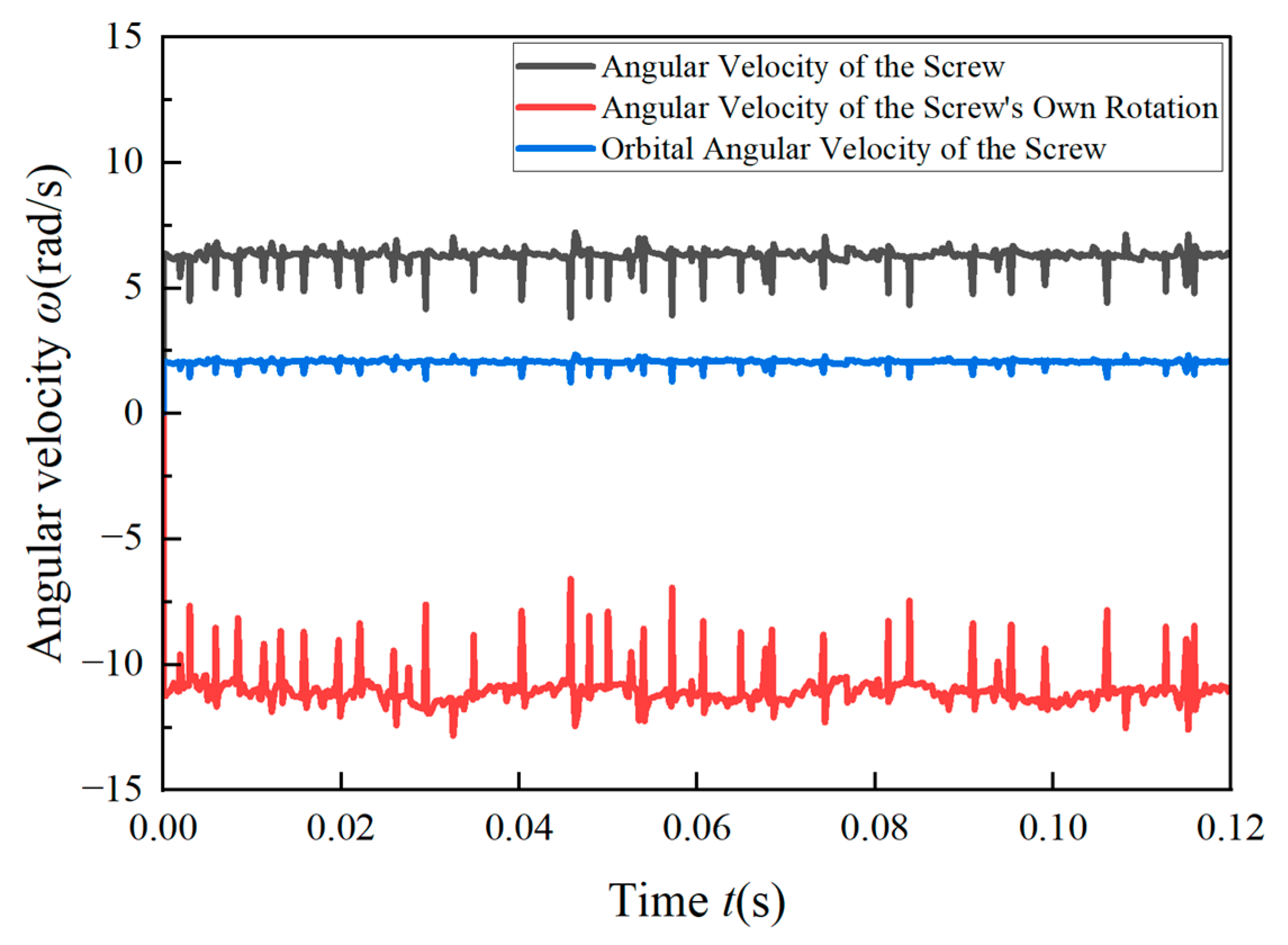
3.3. Simulation of the Clamping Force Tracking Phase
4. Mechanics Simulation Analysis Considering Assembly Errors
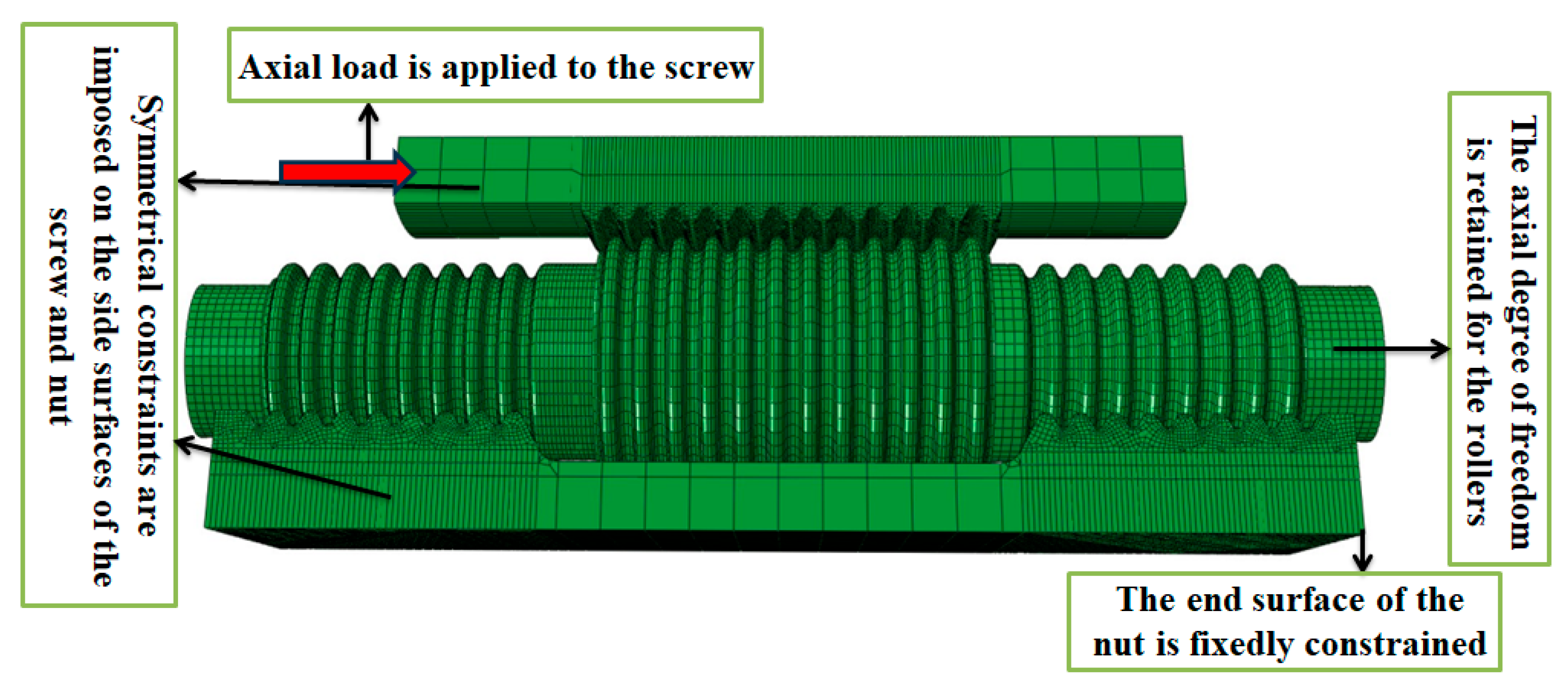
4.1. Finite Element Model of the DPRS
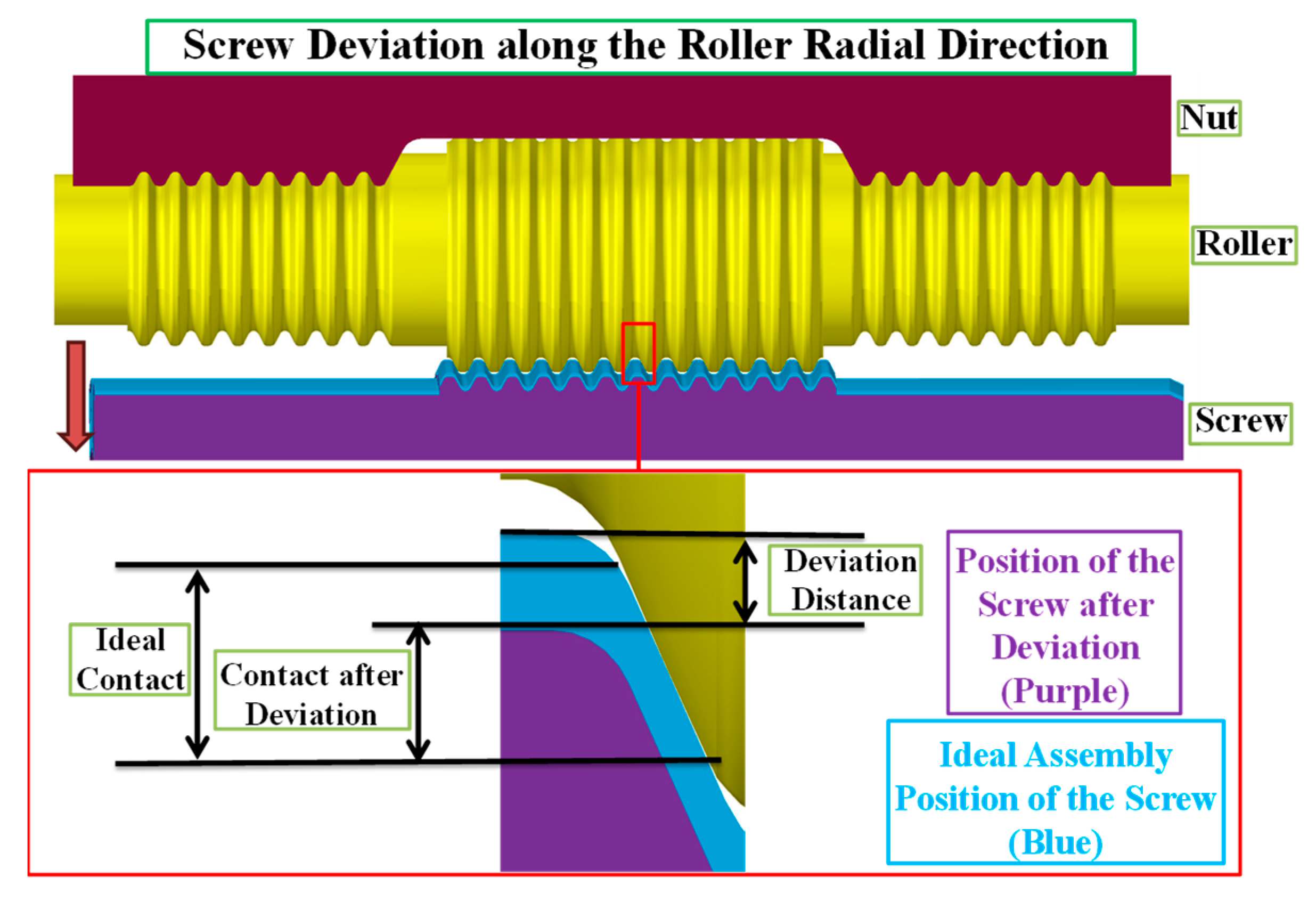
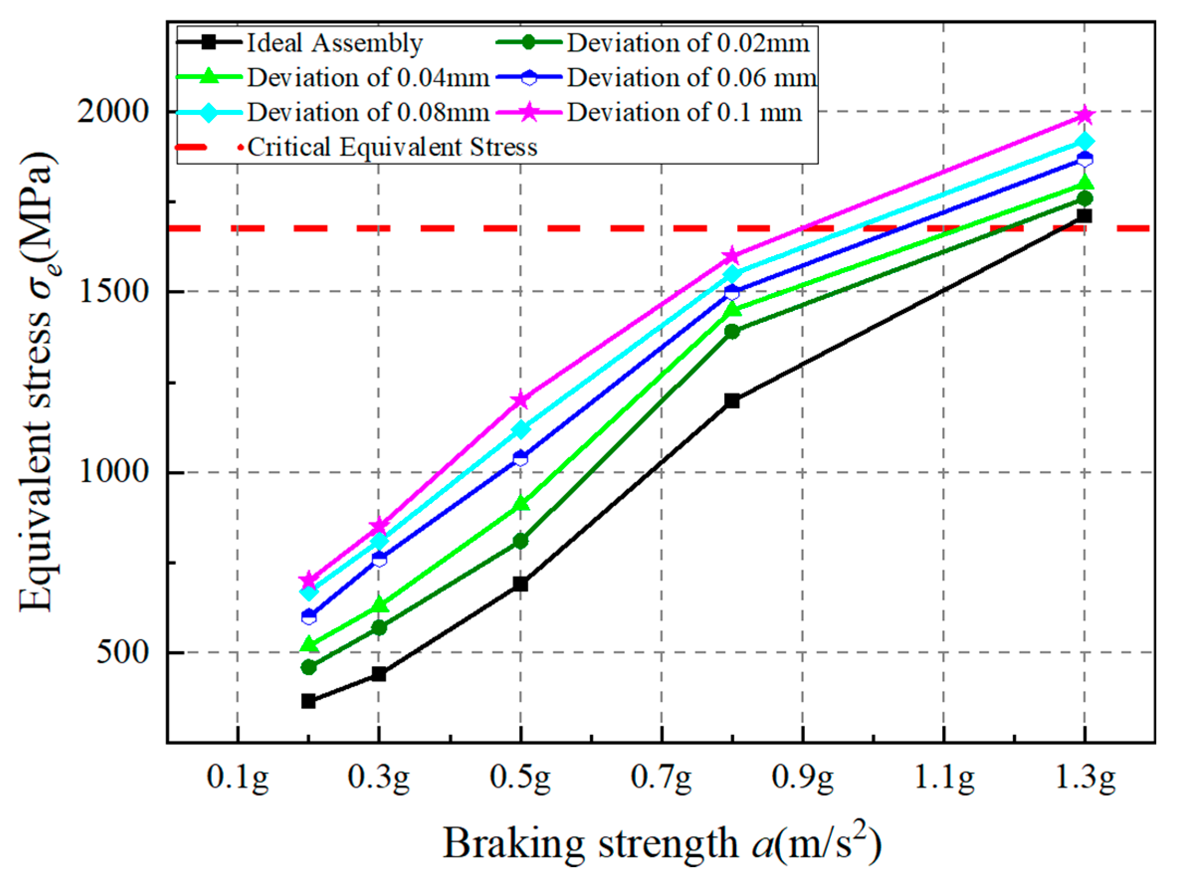
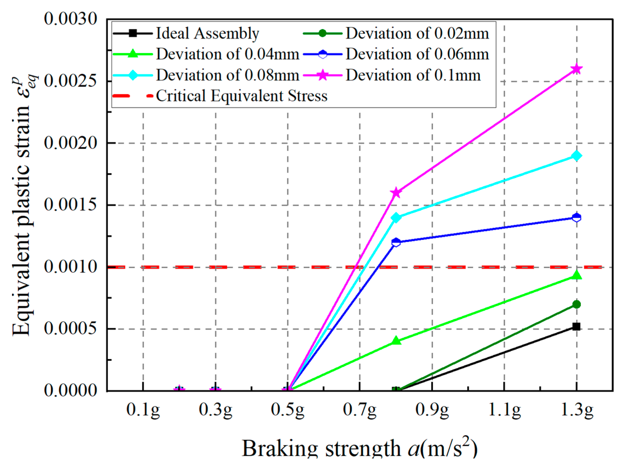
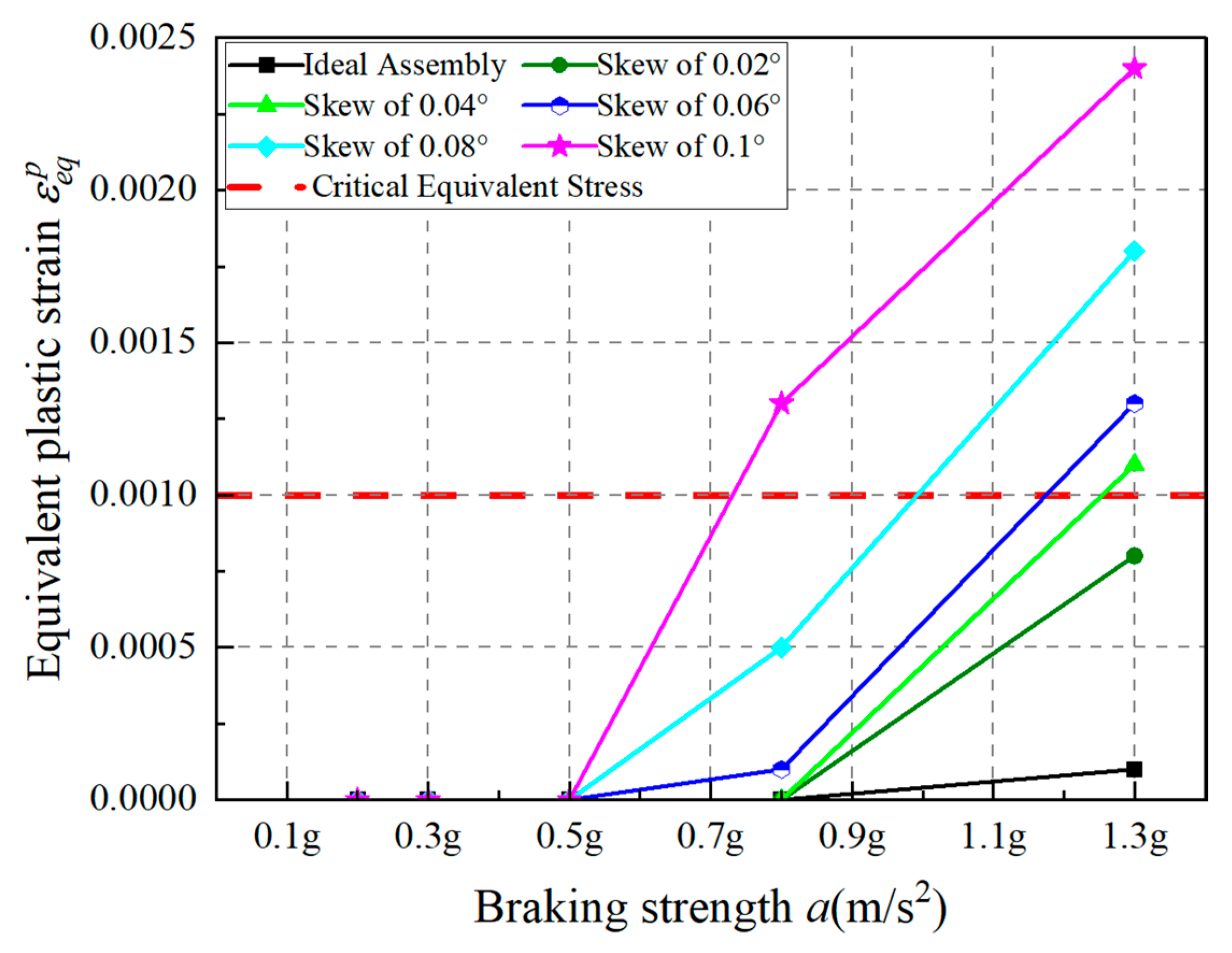
4.2. Mechanical Analysis of Screw Offset Error
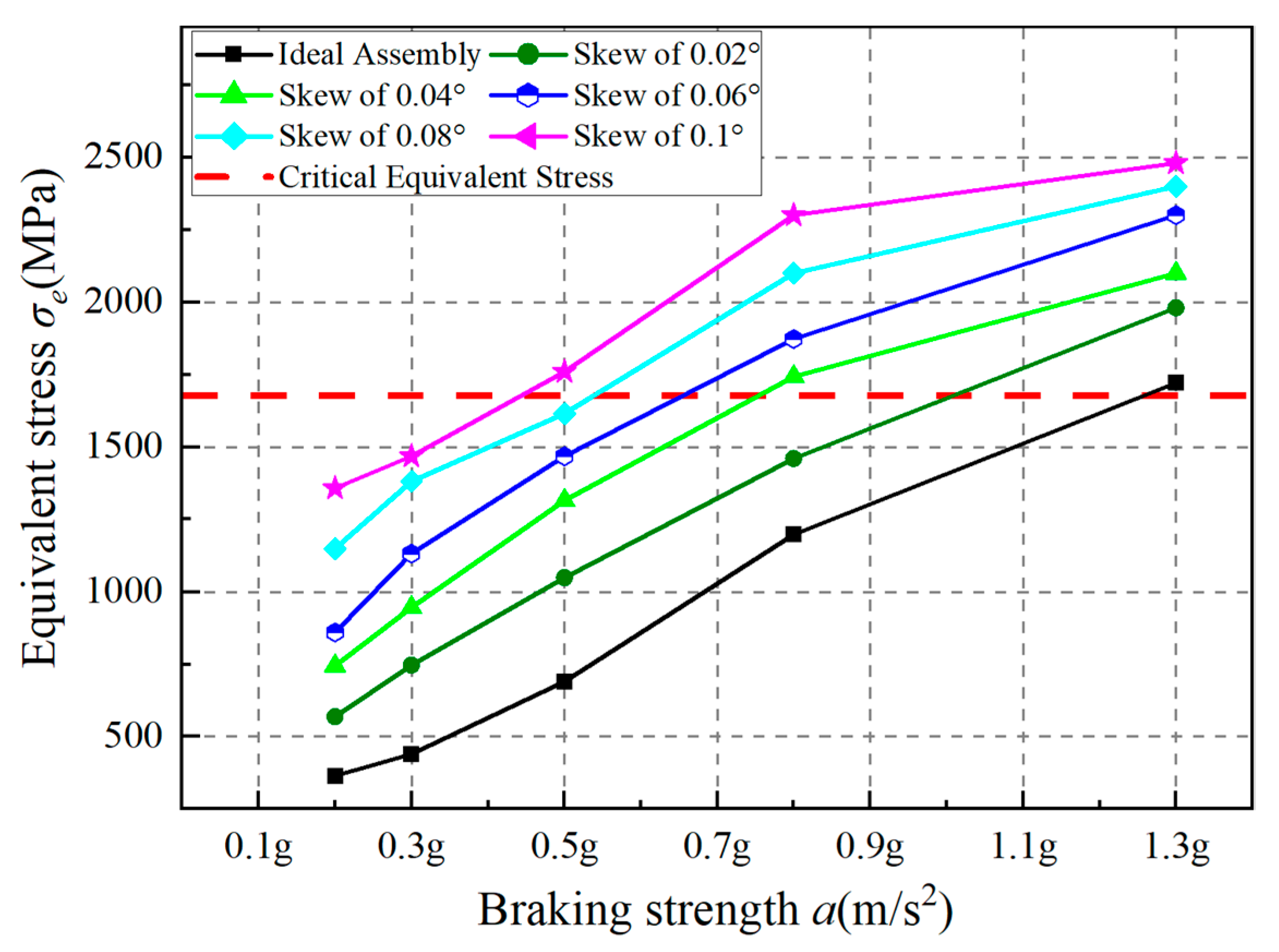
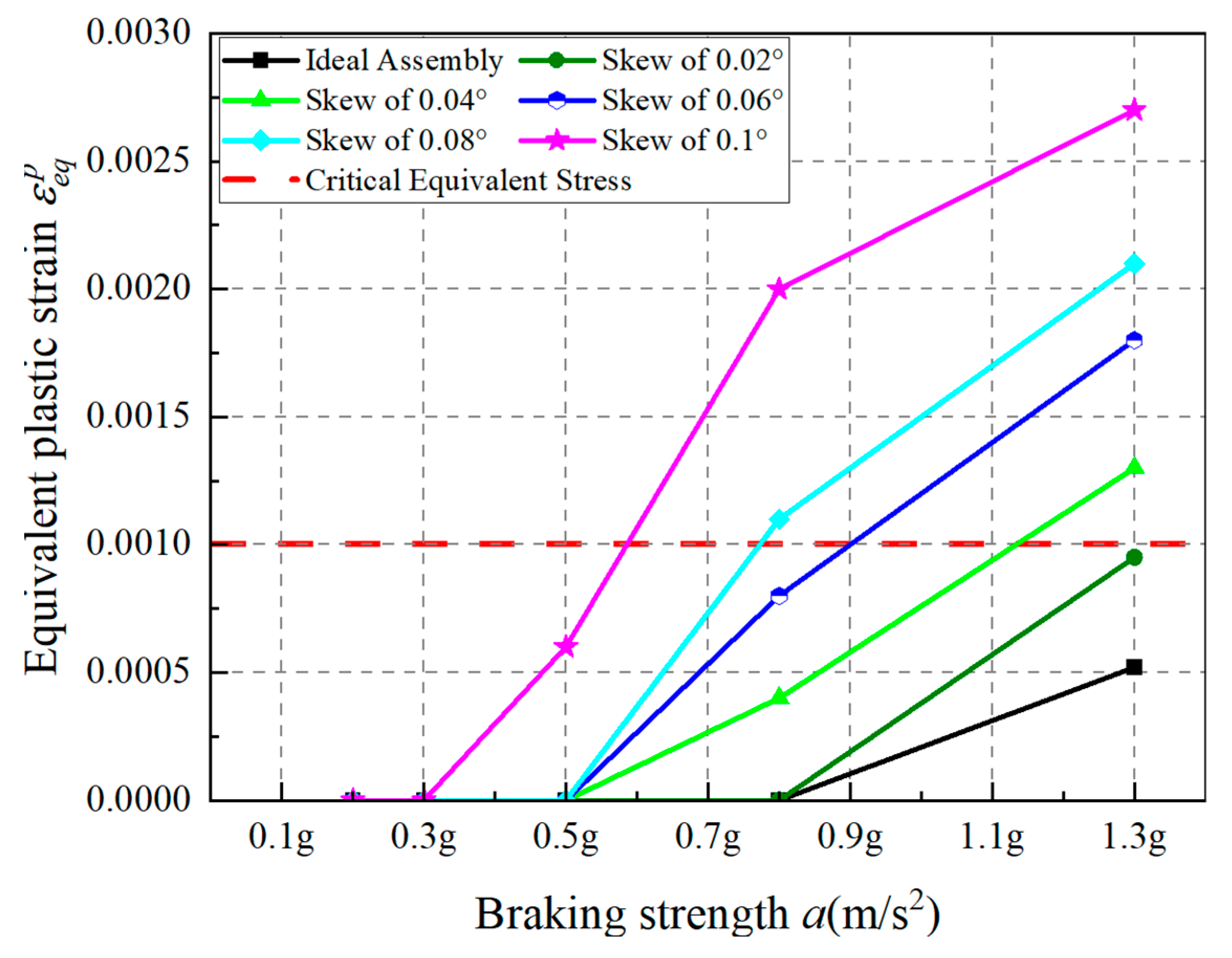
4.3. Analysis of Roller Misalignment Error
5. Conclusions
- (1)
- As braking intensity increases, the axial contact force acting on the DPRS mechanism also increases, resulting in a higher clamping force between the brake disc and friction pad. Furthermore, the maximum braking force should meet regulatory requirements, indicating that the designed DPRS should also satisfy relevant braking standards.
- (2)
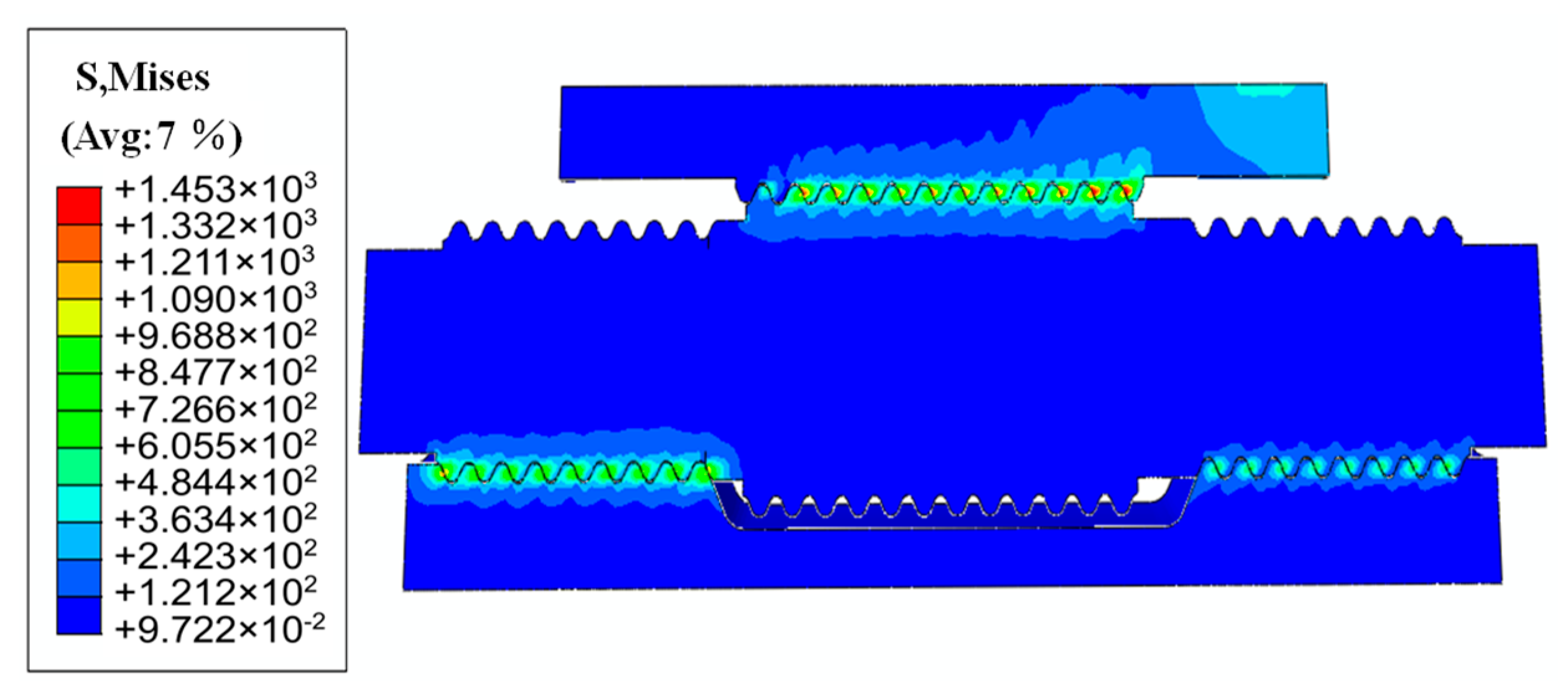
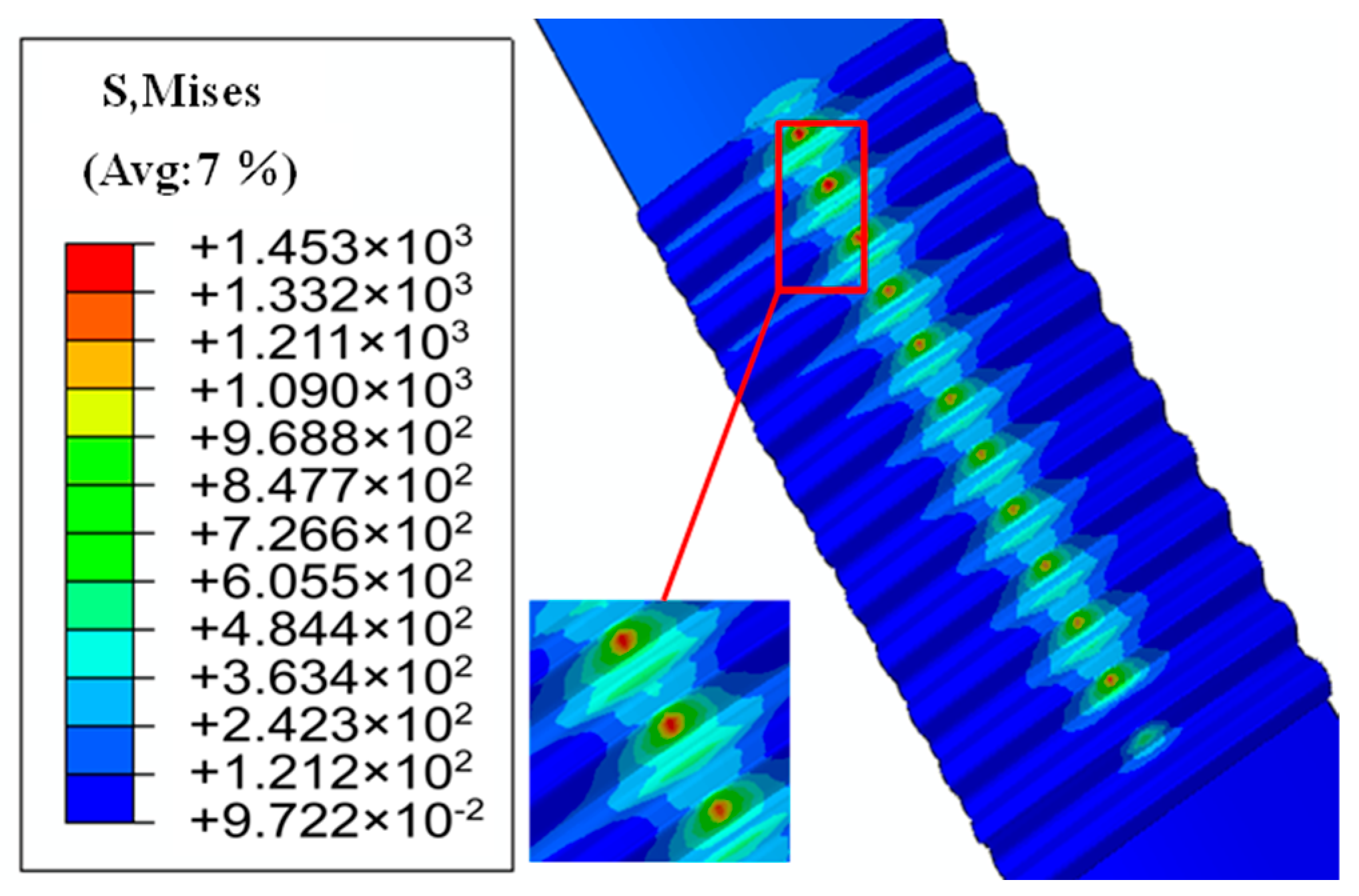
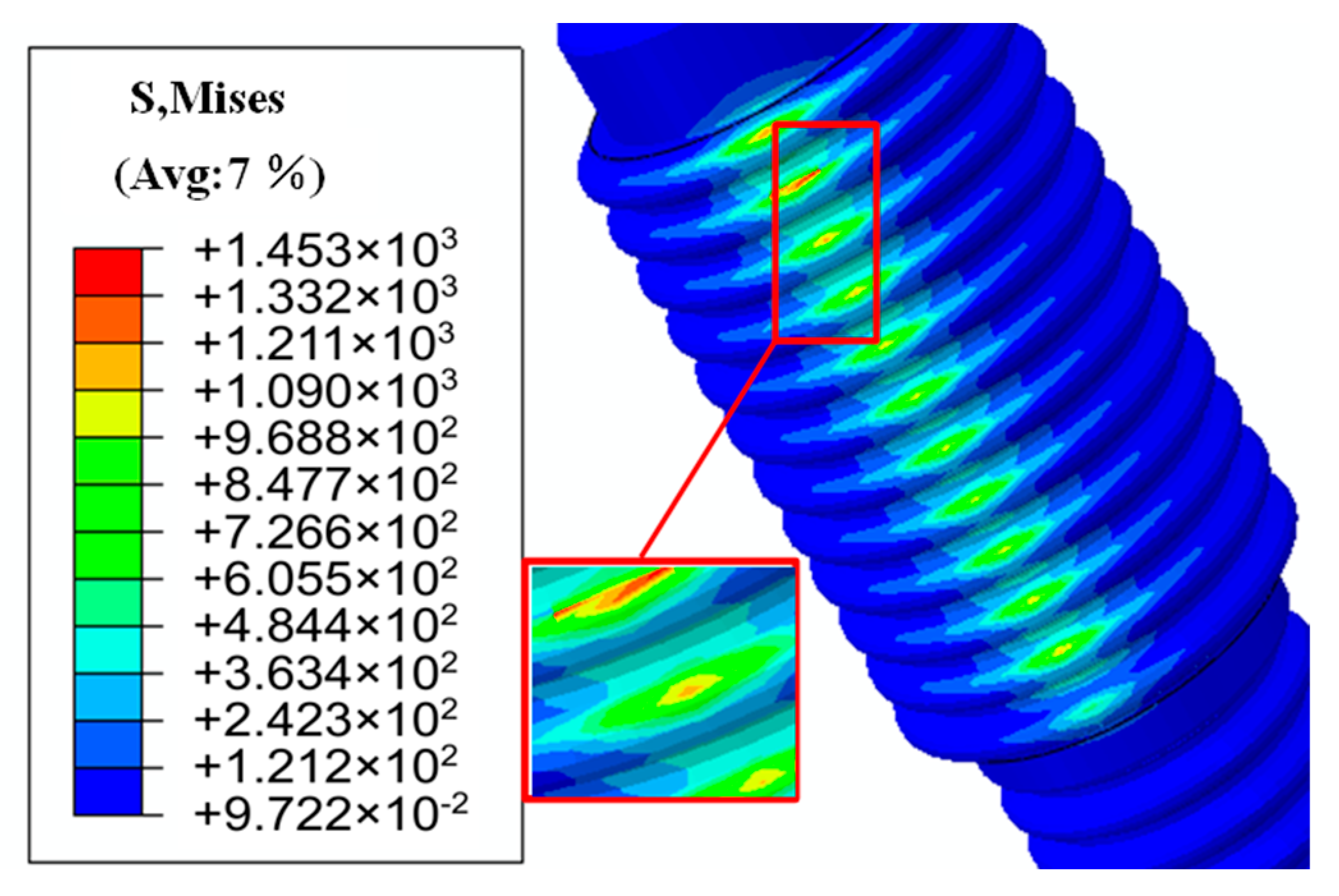
- Both screw offset and roller misalignment errors lead to increased contact stress in the DPRS mechanism. Screw offset has a more significant effect on the contact stress at the screw side, whereas roller misalignment affects the contact stress on both the screw and nut sides.
- (3)
- The DPRS mechanism will exceed the critical equivalent plastic strain under specific braking intensities (e.g., 0.8–1.3 g) when either the screw’s deviation distance surpasses 0.06 mm or the roller’s inclination angle exceeds 0.04°, thereby compromising the normal operation of DPRS and the operational reliability of the EMB system actuator.
Author Contributions
Funding
Data Availability Statement
Conflicts of Interest
References
- Di, Y.; Zhou, J.; Lu, J.; Qin, J.; Wei, Y.; Wang, C.; Hao, C.; Miu, X. Functional safety concept design of EMB brake-by-wire system based on vehicle dynamics. J. Automot. Saf. Energy Effic. 2024, 15, 830–838. [Google Scholar]
- Yang, X.; Chen, S. Technical application and prospect of modern vehicle ESP systems. In Proceedings of the 16th Henan Automotive Engineering Science and Technology Symposium, Henan Society of Automotive Engineers, Kaifeng, China, 21 September 2019; pp. 294–297. [Google Scholar]
- Wu, T.; Rong, J.; Wang, J.; Sun, W.; Chu, L.; Ge, L. Dynamic braking force distribution strategy for steering-braking intensities. Automot. Eng. 2024, 46, 1755–1765. [Google Scholar]
- Zhang, M.; Zu, L.; Xu, Z. Experimental research on influencing factors of ball screw transmission efficiency. Chin. J. Sci. Instrum. 2023, 44, 175–183. [Google Scholar]
- Hu, R.; Wei, P.; Du, X.; Liu, S.; Zhang, N.; Luo, L.; Zhu, C. Multi-objective optimization and accelerated experimental research on load distribution of planetary roller screw mechanism. Tribol. Int. 2024, 199, 110046. [Google Scholar]
- Zhao, B. Thermo-Mechanical Coupling Analysis and Experimental Study of a Differential Planetary Roller Screw Mechanism; Chongqing University: Chongqing, China, 2022. [Google Scholar]
- Liu, Y. Design of Motion Control System for Electric Gough-Stewart Platform Based on PLC Open; Beijing University of Technology: Beijing, China, 2017. [Google Scholar]
- Mugnaini, M.; Addabbo, T.; Fort, A.; Elmi, A.; Landi, E.; Vignoli, V. Magnetic brakes material characterization under accelerated testing intensities. Reliab. Eng. Syst. Saf. 2020, 193, 106614. [Google Scholar]
- Zhao, C. Design and Research of the Actuator for Automotive Electromechanical Brake System; Nanjing University of Science and Technology: Nanjing, China, 2009. [Google Scholar]
- Houhua, J.; Ruixue, F.; Qinggan, L. Design and test of electro-mechanical brake experiment system. In Proceedings of the 6th CAA International Conference on Vehicular Control and Intelligence (CVCI), Nanjing, China, 28–30 October 2022. [Google Scholar]
- Shen, C.; Wang, J.; Lin, Y. Modeling and experimental study of the brake actuator in an electromechanical brake system. Trans. Chin. Soc. Agric. Mach. 2007, 38, 30–33. [Google Scholar]
- Lisowski, F. The analysis of displacements and the load distribution between elements in a planetary roller screw. Appl. Mech. Mater. 2014, 680, 326–329. [Google Scholar]
- Yang, C.; Ji, J.; Tong, X.; Huang, Q.; Quan, X. Load distribution modeling and simulation of a differential planetary roller screw mechanism. Ship Eng. 2023, 45, 88–94. [Google Scholar]
- Cui, G. Analysis and Study on Contact Characteristics and Load-Carrying Capacity of a Differential Planetary Roller Screw Pair; Nanjing University of Science and Technology: Nanjing, China, 2017. [Google Scholar]
- Ma, S.; Cai, W.; Wu, L.; Liu, G.; Peng, C. Modelling of transmission accuracy of a planetary roller screw mechanism considering errors and elastic deformations. Mech. Mach. Theory 2019, 134, 151–168. [Google Scholar]
- Zheng, Z.; Chen, Y.; Chen, B.; Du, X.; Li, C. Meshing performance investigations on a novel point-contact hourglass worm drive with backlash-adjustable. Mech. Mach. Theory 2020, 149, 103841. [Google Scholar]
- Yao, Q.; Zhang, M.C.; Ma, S. Structural design for planetary roller screw mechanism based on the developed contact modelling. Tribol. Int. 2022, 171, 107570. [Google Scholar]
- Hu, R.; Wei, P.; Zhou, P.; Liu, H.; Du, X.; Zhu, C. A roller taper modification method for load distribution optimization of planetary roller screw mechanism. J. Adv. Mech. Des. Syst. Manuf. 2022, 16, JAMDSM0032. [Google Scholar]
- Zhang, Q.; Jin, L.; Jin, B. Research on control strategy of electromechanical braking system for dynamic control. Automot. Eng. 2022, 44, 736–746+755. [Google Scholar]
- GB 12676-2014; Technical Requirements and Test Methods for Braking Systems of Commercial Vehicles and Trailers. Standardization Administration of China: Beijing, China, 2014.
- Xu, Q.; Wang, S.; Zhao, G.; Huang, Y. Differential effect analysis and suppression of PWG-type differential screw. Mach. Des. Res. 2015, 31, 57–61. [Google Scholar]
- Wang, S. Design and Stability Analysis of an Electromechanical Brake (EMB) System for Vehicles; Anhui University of Science and Technology: Anhui, China, 2017. [Google Scholar]
- Wu, W. Contact Characteristics Analysis and Parameter Optimization of Planetary Roller Screw Pair Considering Comprehensive Errors; Nanjing University of Science and Technology: Nanjing, China, 2023. [Google Scholar]
- Chen, S. Research on Thread Contact Parameters and Contact Intensity Analysis of Planetary Roller Screw Pair; Nanjing University of Science and Technology: Nanjing, China, 2019. [Google Scholar]


| Parameter Name | Numerical Value |
|---|---|
| Maximum pressure of brake FR (N) | 17,163 |
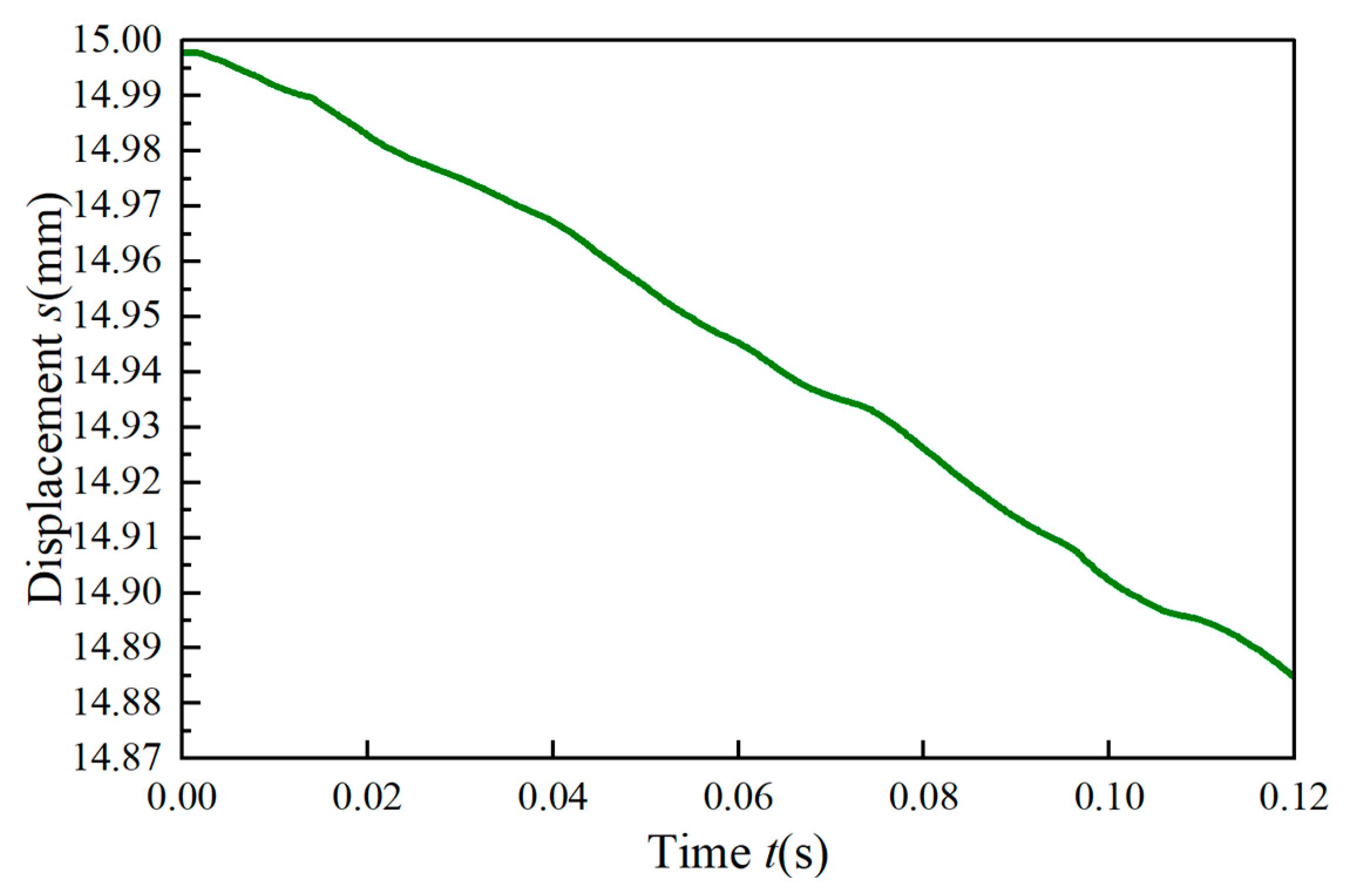
| Gap elimination time t (s) | 0.12 |
| Brake Clearance (unilateral) s (mm) | 0.1 |
| Components | Kinematic Pair |
|---|---|
| Ground and lead screw | Revolute joint |
| Cage and lead screw | Roller joint |
| Nuts and lead screws | Prismatic joint |
| Nut and piston | Fixed joint |
| Parameter | Lead Screw Angular Speed ω (rad/s) | Roller Angular Velocity ω (rad/s) | Nut Displacement s (mm) |
|---|---|---|---|
| Simulated results | 6.25 | 11.50 | 0.115 |
| Theoretical value | 6.28 | 11.91 | 0.117 |
| Relative error | 0.4% | 3% | 2% |
| Braking Intensities a (m/s2) | Axial Load F (N) |
|---|---|
| 0.2 g | 216 |
| 0.3 g | 306 |
| 0.5 g | 550 |
| 0.8 g | 1127 |
| 1.0 g | 1300 |
| 1.3 g | 1475 |
| Plastic Strain | Stress σe (MPa) |
|---|---|
| 0 | 1617 |
| 0.001587 | 1699 |
| 0.002983 | 1894 |
| 0.015157 | 2107 |
| 0.025784 | 2120 |
Disclaimer/Publisher’s Note: The statements, opinions and data contained in all publications are solely those of the individual author(s) and contributor(s) and not of MDPI and/or the editor(s). MDPI and/or the editor(s) disclaim responsibility for any injury to people or property resulting from any ideas, methods, instructions or products referred to in the content. |
© 2025 by the authors. Licensee MDPI, Basel, Switzerland. This article is an open access article distributed under the terms and conditions of the Creative Commons Attribution (CC BY) license (https://creativecommons.org/licenses/by/4.0/).
Share and Cite
Dong, X.; Zhao, L.; Yao, P.; Hu, Y.; Quan, L.; Zhang, D. Contact Analysis of EMB Actuator Considering Assembly Errors with Varied Braking Intensities. Vehicles 2025, 7, 70. https://doi.org/10.3390/vehicles7030070
Dong X, Zhao L, Yao P, Hu Y, Quan L, Zhang D. Contact Analysis of EMB Actuator Considering Assembly Errors with Varied Braking Intensities. Vehicles. 2025; 7(3):70. https://doi.org/10.3390/vehicles7030070
Chicago/Turabian StyleDong, Xinyao, Lihui Zhao, Peng Yao, Yixuan Hu, Liang Quan, and Dongdong Zhang. 2025. "Contact Analysis of EMB Actuator Considering Assembly Errors with Varied Braking Intensities" Vehicles 7, no. 3: 70. https://doi.org/10.3390/vehicles7030070
APA StyleDong, X., Zhao, L., Yao, P., Hu, Y., Quan, L., & Zhang, D. (2025). Contact Analysis of EMB Actuator Considering Assembly Errors with Varied Braking Intensities. Vehicles, 7(3), 70. https://doi.org/10.3390/vehicles7030070