

Basic Study on Operation Control Systems of Internal Combustion Engines in Hybrid Small Race Cars to Improve Dynamic Performance

 , , , and
Abstract
1. Introduction
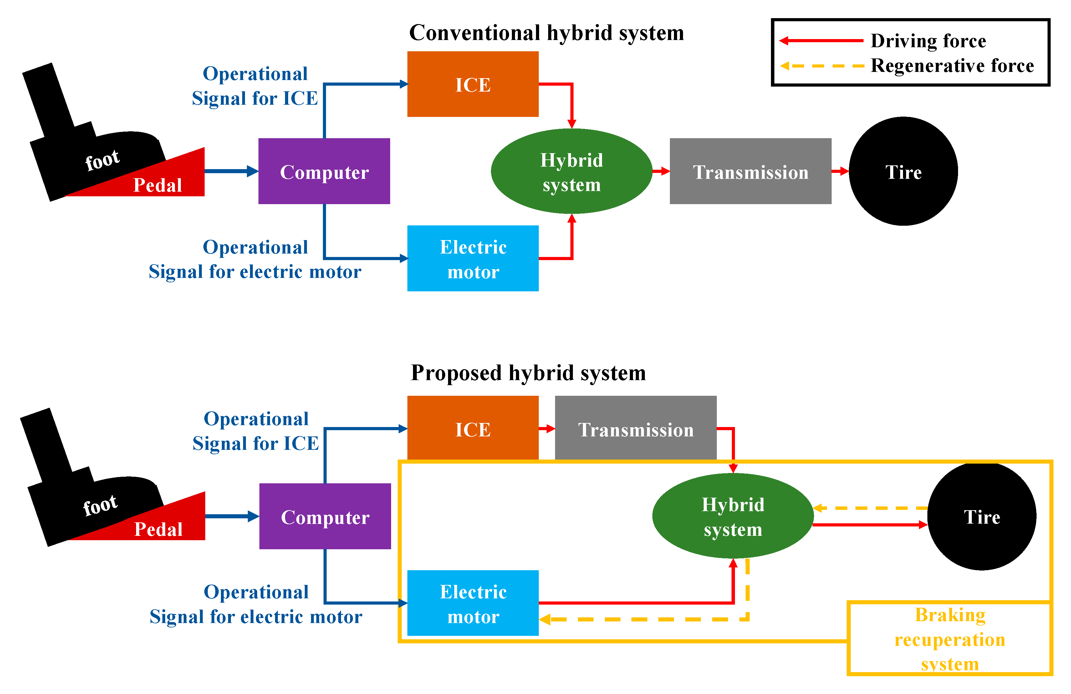
2. Hybrid System for Small Race Cars
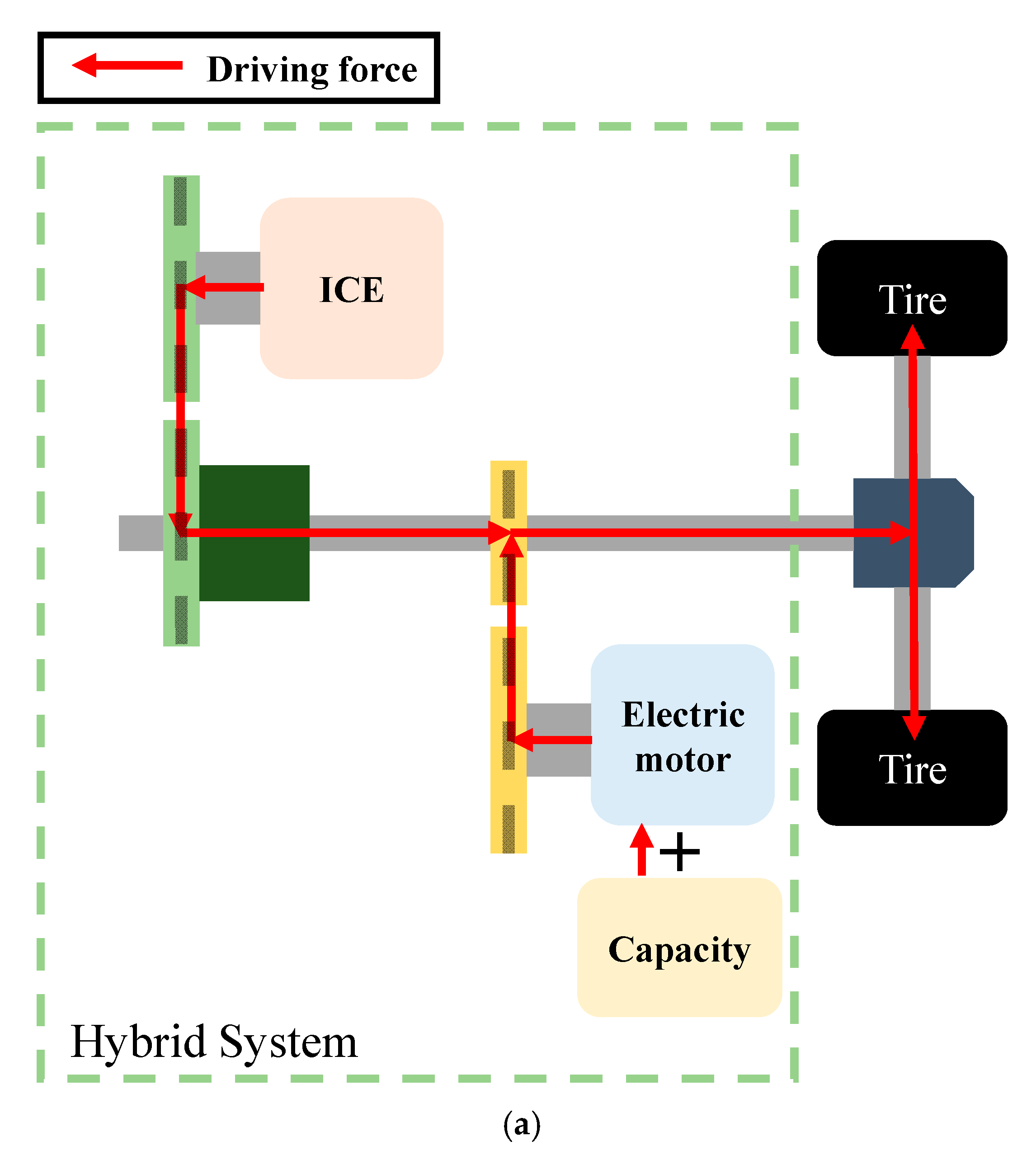
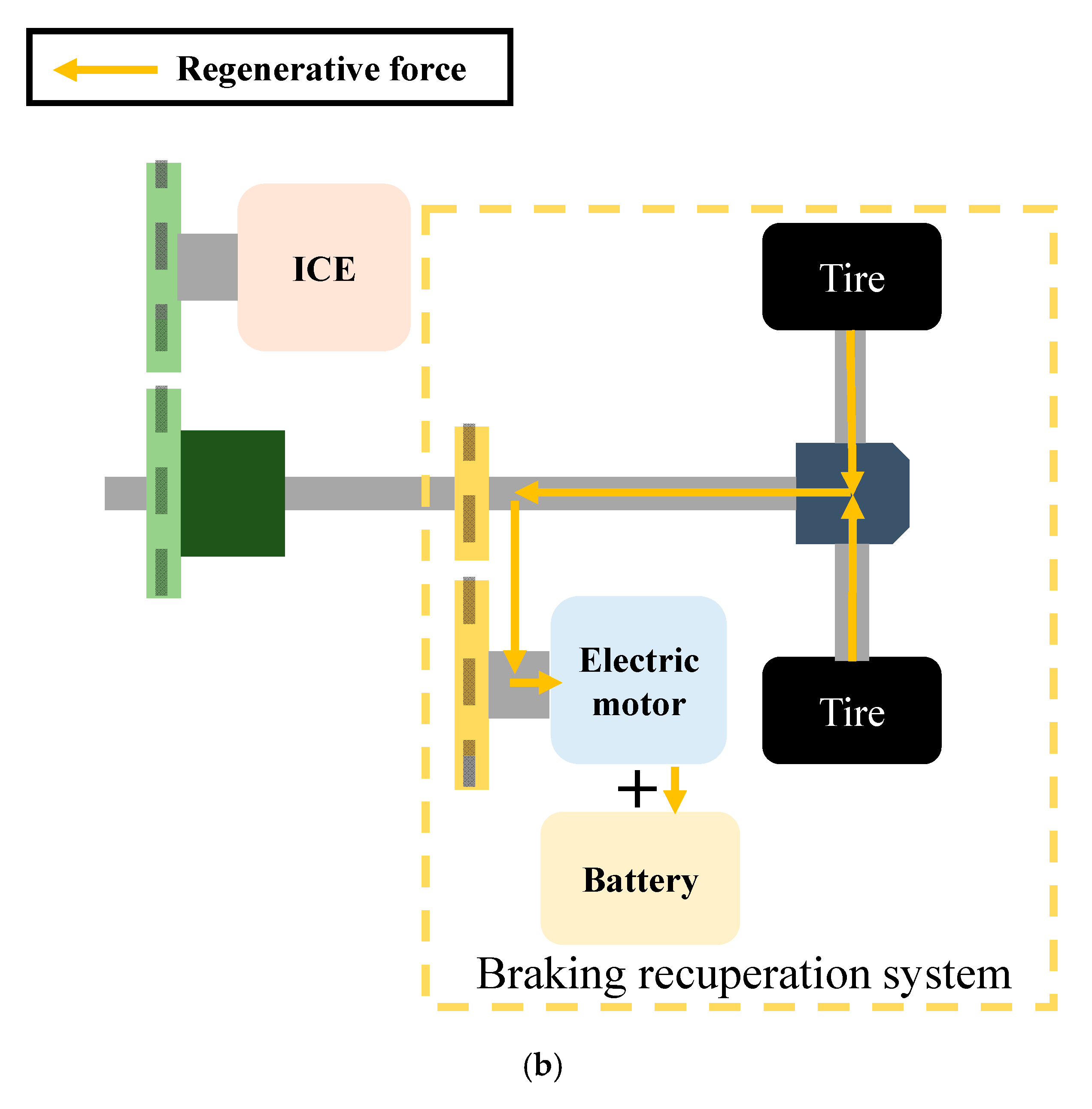
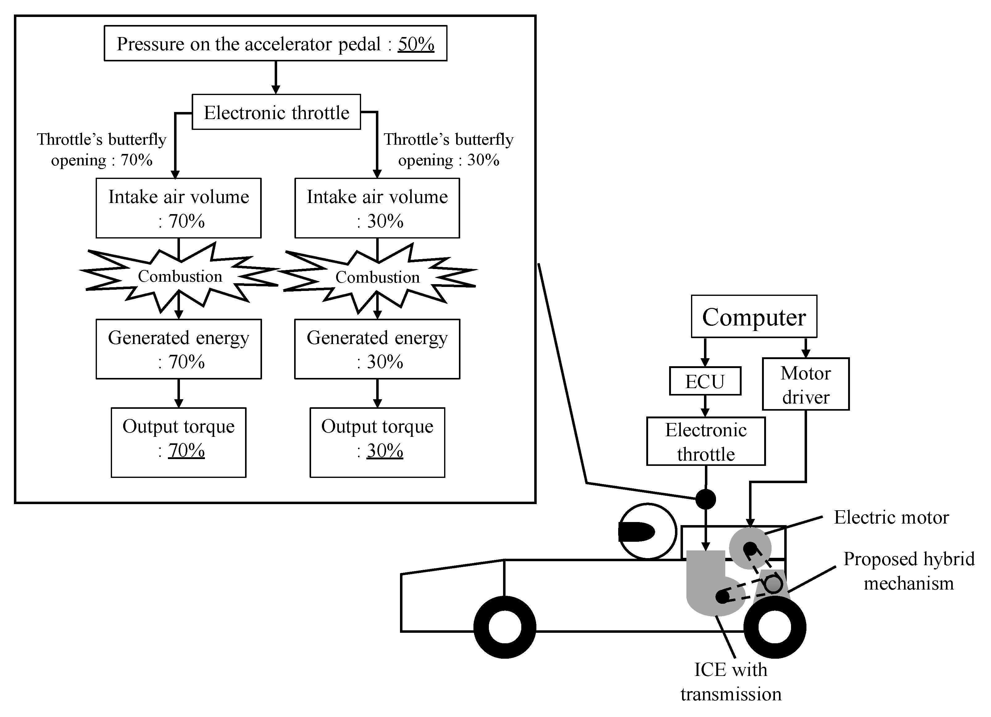
2.1. Proposed Hybrid System for Small Race Cars
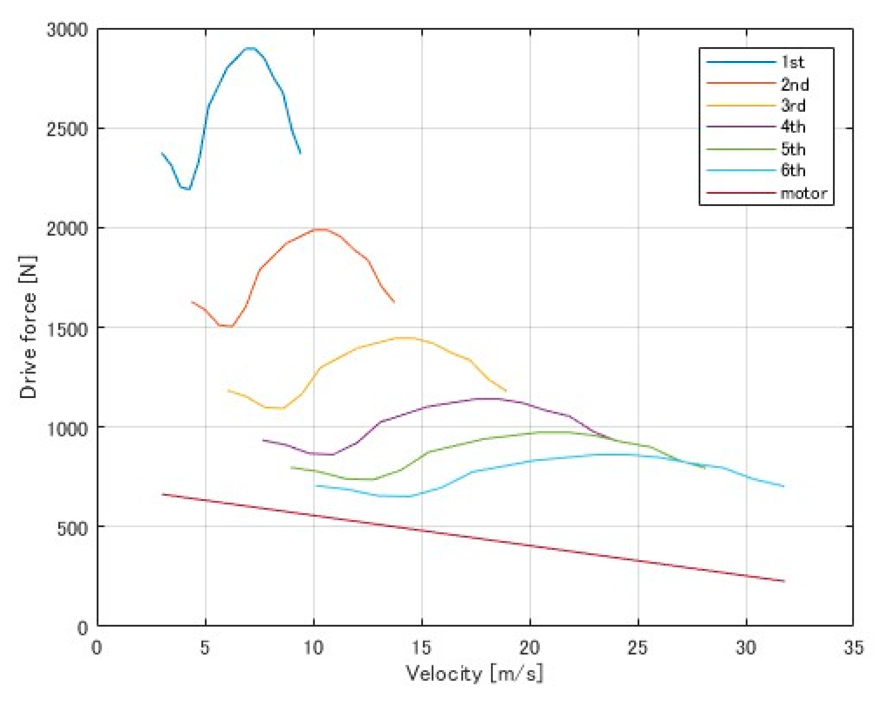
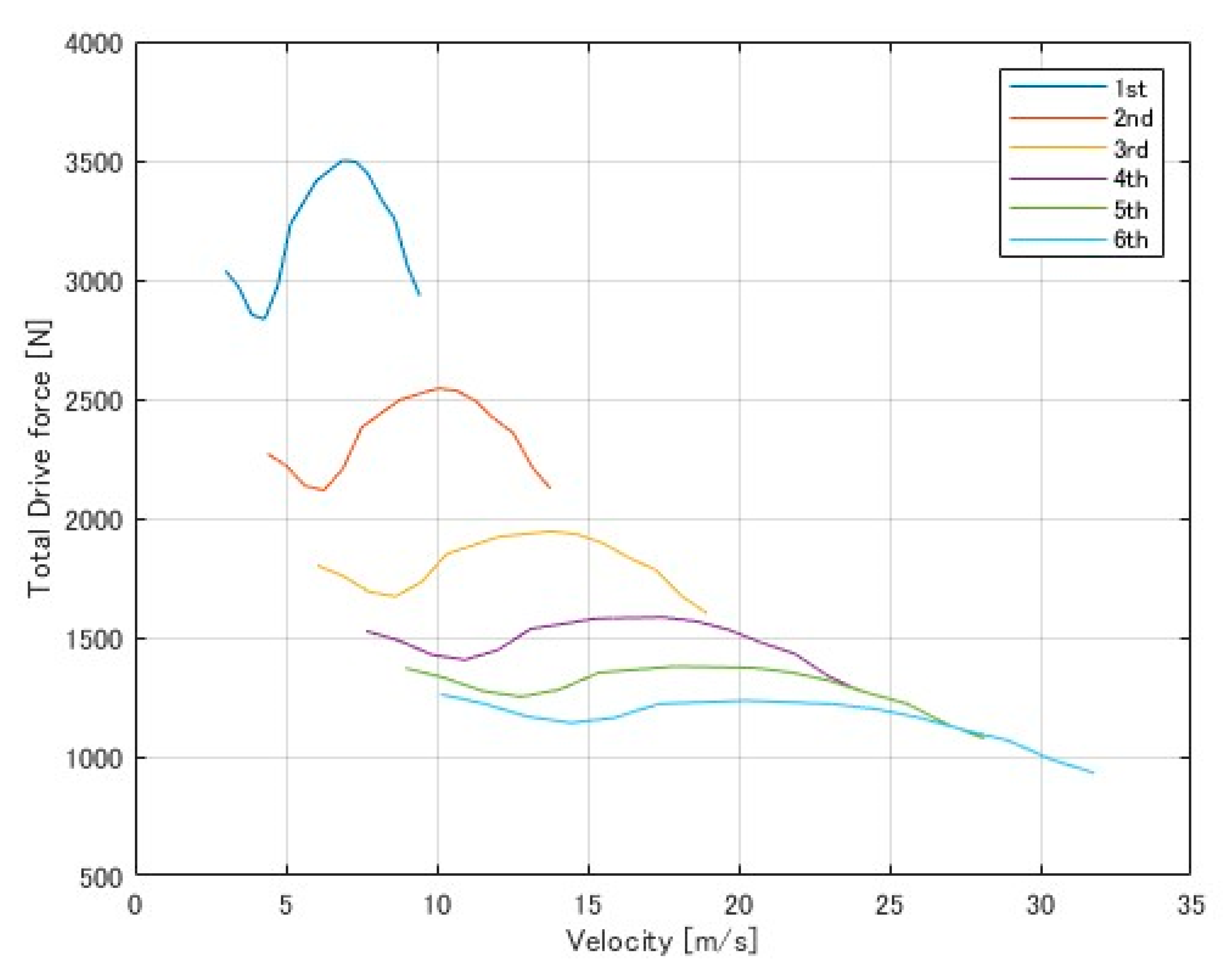
2.2. Driving-Force Simulation of the Proposed Hybrid System
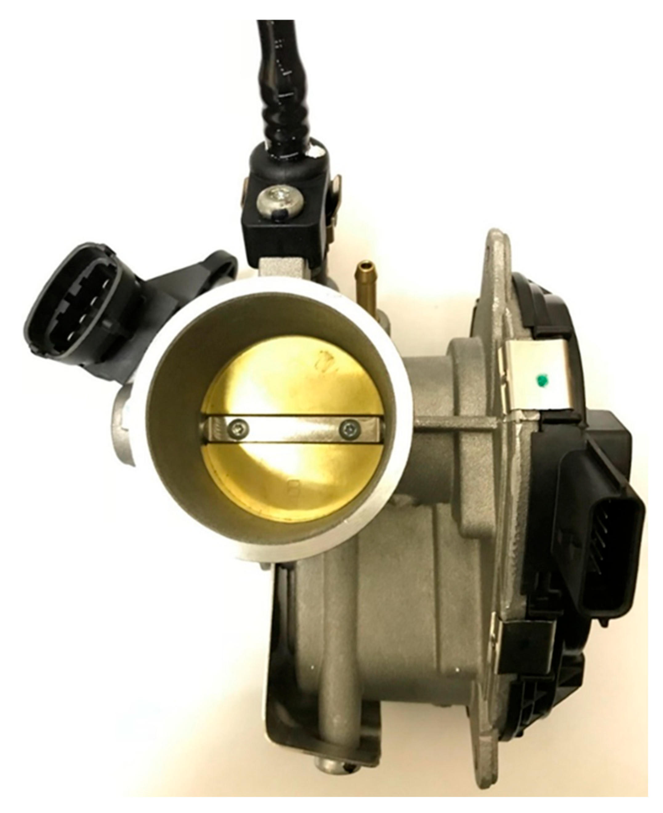
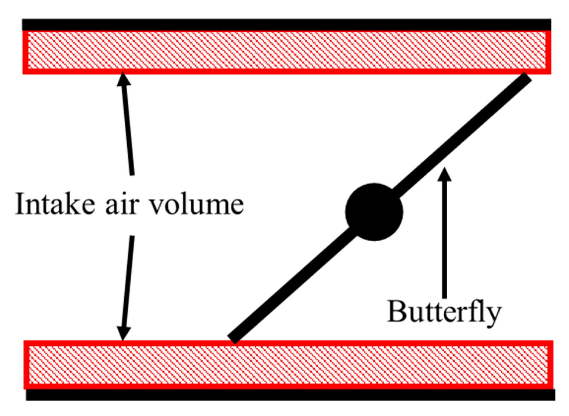
3. Electronic Throttle
3.1. Throttle Control of ICE
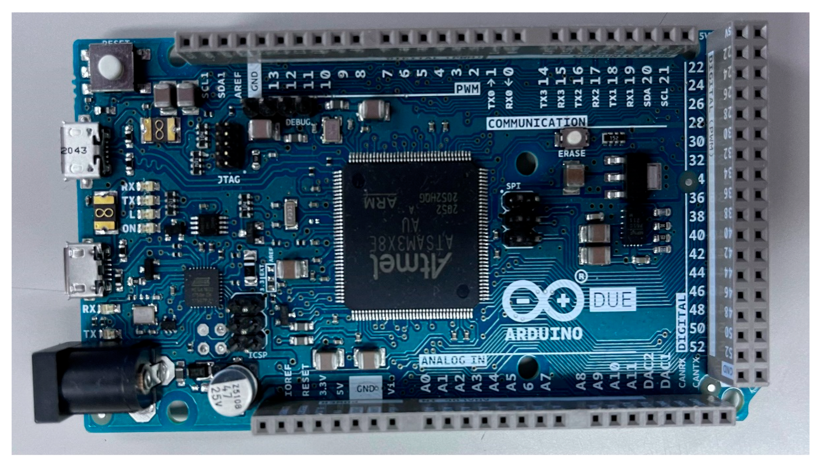
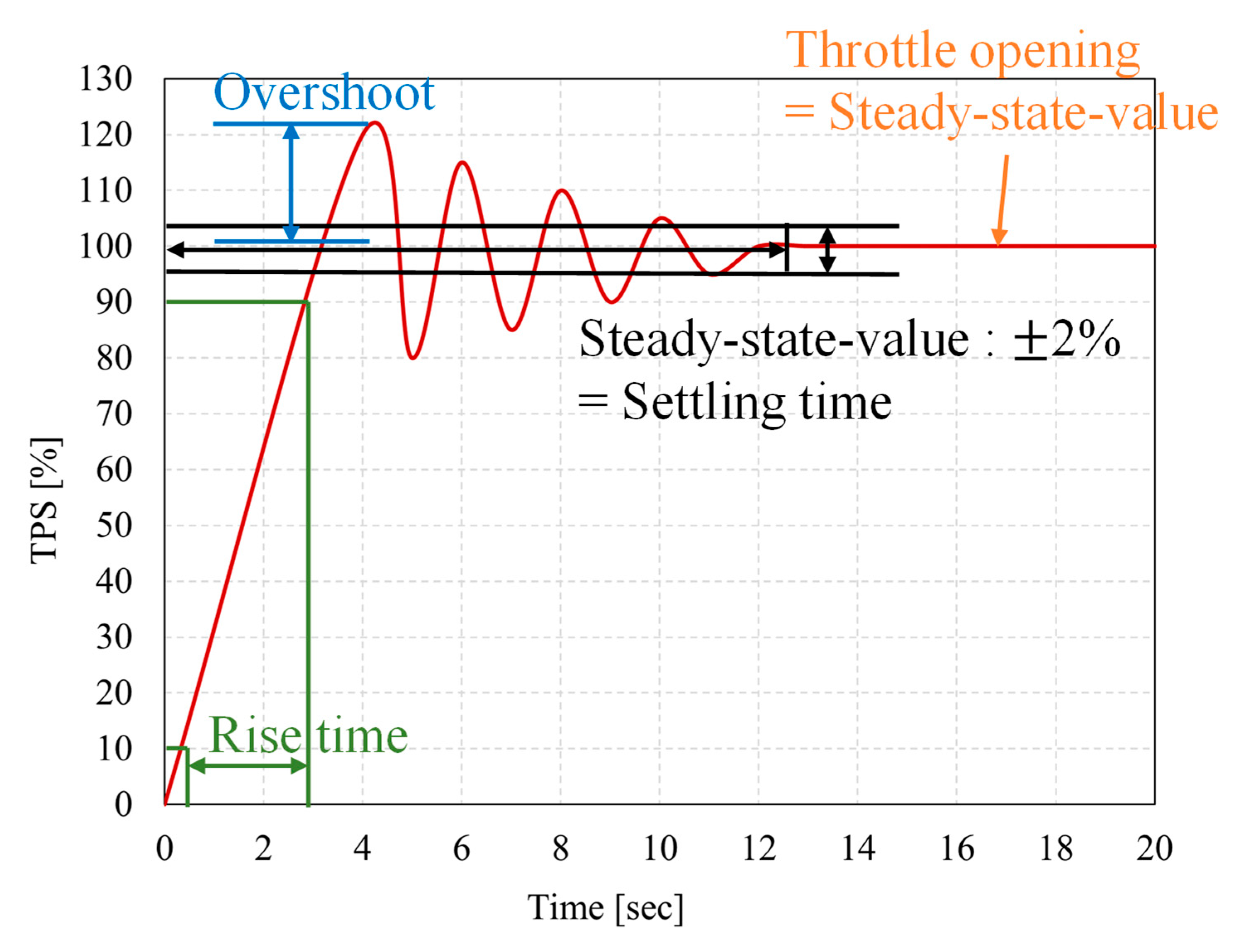
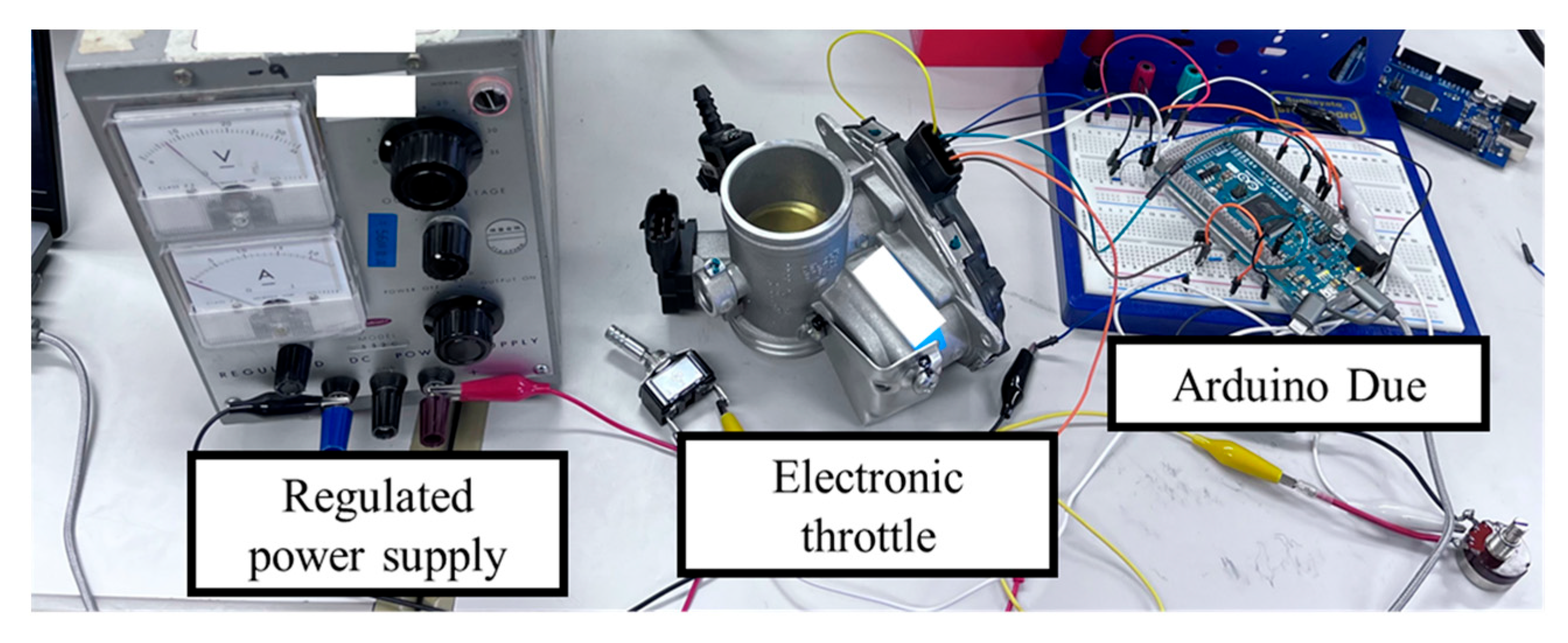
3.2. Experimental Procedure
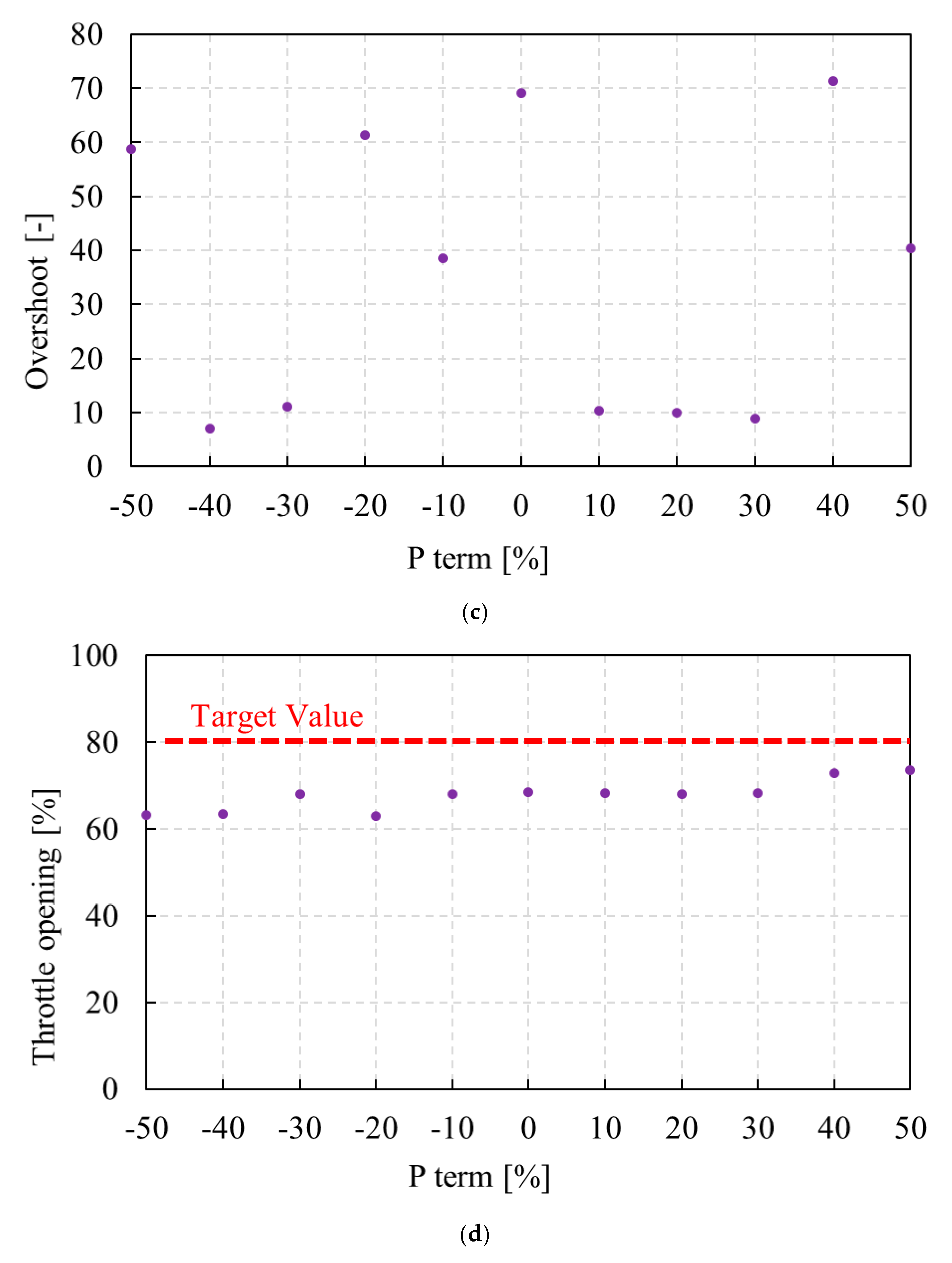
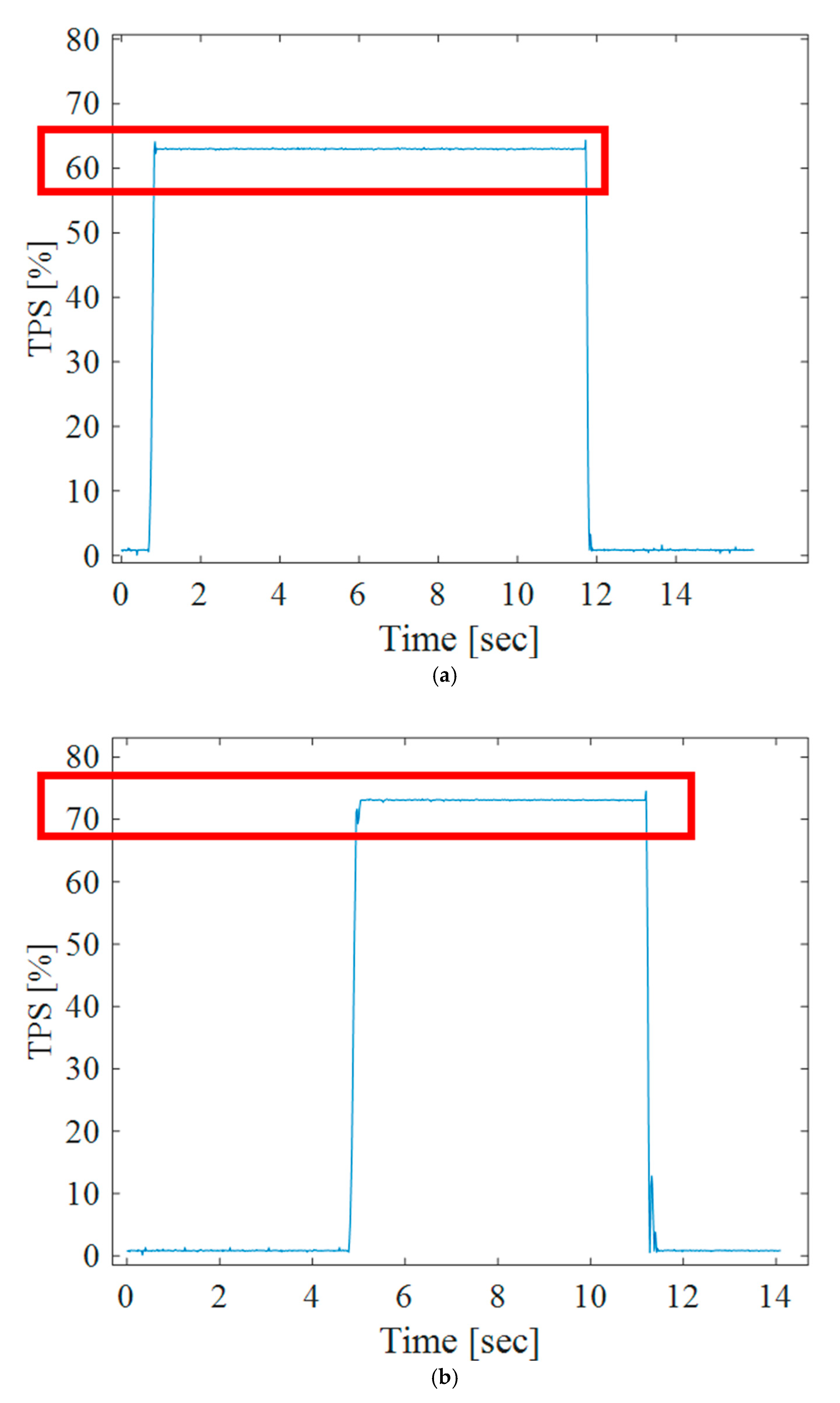
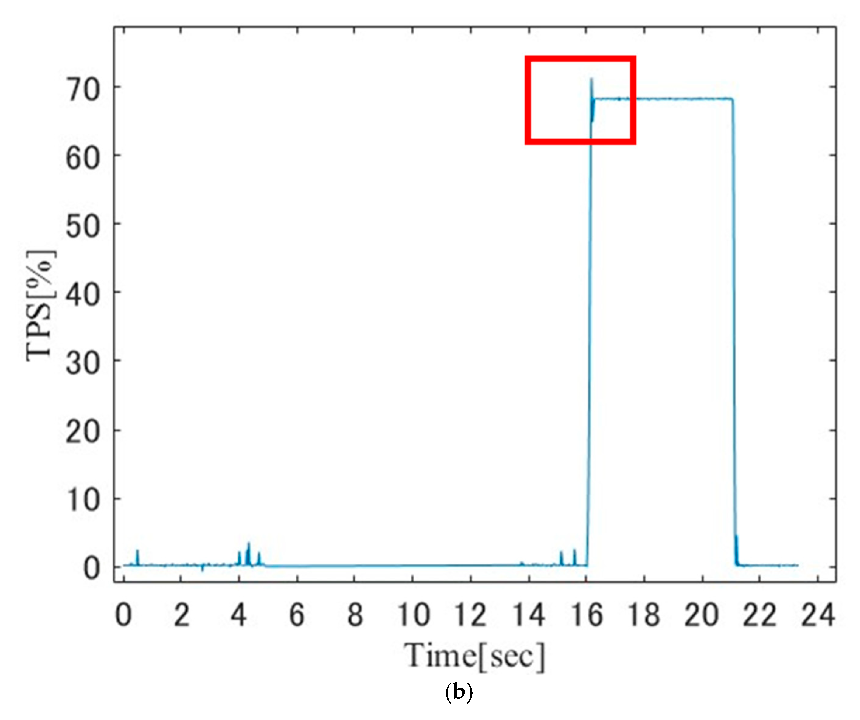
3.3. Experimental Results
4. Discussion
5. Conclusions
Author Contributions
Funding
Data Availability Statement
Conflicts of Interest
References
- Asakura, Y. Hybrid Vehicle; Toyota Motor Corporation: Toyota, Japan, 2009. [Google Scholar]
- Kobayashi, I.; Ogawa, K.; Uchino, D.; Ikeda, K.; Kato, T.; Endo, A.; Bin Peeie, M.H.B.; Narita, T.; Kato, H. A basic study on hybrid systems for small race car to improve dynamic performance using lap time simulation. Actuators 2022, 11, 173. [Google Scholar] [CrossRef]
- Lot, R.; Evangelou, S. Lap time optimization of a sports series hybrid electric vehicle. Proc. World Congr. Eng. 2013, 3, 1711–1716. [Google Scholar]
- Lambert, S.; Maggs, S.; Faithfull, P.; Vinsome, A. Development of A hybrid electric racing car. In Proceedings of the IET HEVC 2008-Hybrid and Eco-Friendly Vehicle Conference, Coventry, UK, 8–9 December 2008; Institution of Engineering and Technology: London, UK, 2008; Volume 6, p. 6. [Google Scholar] [CrossRef]
- Formula SAE Hybrid. Available online: https://www.sae.org/attend/student-events/formula-hybrid/ (accessed on 7 March 2025).
- Sato, Y.; Narita, T.; Kato, H.; Okamoto, T. Proposal of power synthesis mechanism in hybrid system for compact racing car: A fundamental mechanism in hybrid system for compact racing car: A fundamental consideration on structural design and vehicle movement performance. Proc. Sch. Eng. Tokai Univ. E 2018, 43, 31–37. [Google Scholar]
- What Is PID Control? Explains the Mechanism and Operation Image in an Easy-to-Understand Manner! Available online: https://controlabo.com/ (accessed on 16 October 2024).
- Sawut, U.; Tohti, G.; Nakano, K. Identification and robust control of electronic throttle system. Trans. Soc. Instrum. Control Eng. 2003, 39, 1150–1155. [Google Scholar]
- Sawut, U.; Ishii, M.; Yasukawa, H. Modeling and identification of automotive engine control system. Trans. Soc. Instrum. Control Eng. 2005, 41, 373–379. [Google Scholar]
- Hatanaka, A.; Tokuyama, T.; Kusukawa, J.; Seki, T.; Ohshima, K. High voltage and high power destiny technologies for inverter in vehicle. Proc. Soc. Automot. Eng. Jpn. 2020, 51, 1050–1055. [Google Scholar]
- Sugano, C.; Tamura, Y.; Komamura, T. Development of the robust design method for crash analysis—Visualization of conditions for good quality by using pattern recognition and machine learning. Proc. Soc. Automot. Eng. Jpn. 2022, 53, 258–263. [Google Scholar]
- Washikita, Y.; Ohtsuka, T. Model predictive control for systems connected by time-delay elements—Integrated design of feedback and feedforward control. Trans. Soc. Instrum. Control Eng. 2018, 54, 447–457. [Google Scholar]
- Sadamoto, T.; Kobayashi, F.; Kaneko, O. Data–driven design of feedforward controllers with performance guarantee. Trans. Inst. Syst. Control. Inf. Eng. 2020, 33, 201–206. [Google Scholar] [CrossRef]
- Chien, P.-C.; Chen, C.-K. Integrated chassis control and control allocation for all wheel drive electric cars with rear wheel steering. Electronics 2021, 10, 2885. [Google Scholar] [CrossRef]
- Andrez, D.; Jakub, F. The bicycle model of a 4WS car lateral dynamics for lane change controller. IOP Conf. Ser. Mater. Sci. Eng. 2021, 1247, 012021. [Google Scholar] [CrossRef]
- Medina, A.; Bistue, G.; Rubio, A. Comparison of typical controllers for direct yaw moment control applied on an electric race car. Vehicles 2021, 3, 127–144. [Google Scholar] [CrossRef]
- Raksincharoensak, P.; Daisuke, S.; Lidberg, M. Direct yaw moment control for enhancing handling quality of lightweight electric vehicles with large load to curb weight ratio. Appl. Sci. 2019, 9, 1151. [Google Scholar] [CrossRef]
- Woo, S.; Cha, H.; Yi, K.; Jang, S. Active differential control for improved handling performance of front-wheel-drive high-performance vehicle. Int. J. Automot. Technol. 2021, 22, 537–546. [Google Scholar] [CrossRef]
- Karthik, P. Integrated Brake Based Torque Vectoring Control of Vehicle Yaw Rate and Sideslip Angle. Master’s Thesis, University of Pretoria, Hatfield, South Africa, 2018. [Google Scholar]
- Patton, C. Development of Vehicle Dynamics Tools for Motorsports. Ph.D. Thesis, Oregon State University, Corvallis, OR, USA, 2013. [Google Scholar]
- Yamada, H.; Ebashi, Y.; Kobayashi, I.; Kuroda, J.; Uchino, D.; Ogawa, K.; Peeie, M.H.B.; Kato, H.; Narita, T. Internal combustion engine control of hybrid system for small competition vehicles-experimental consideration on installation of throttle-by wire system to improve response. In Proceedings of the Automotive Engineering Society Conference Academic Lectures; Tokai University: Hiratsuka, Japan, 2024. [Google Scholar]
- Heikes, H.; Pelkmann, A.; Barton, A. Investigation on the transient behavior of a Two-Wheeler single cylinder engine close to idling with electronic throttle control. SAE Tech. Pap. 2018. [Google Scholar] [CrossRef]
- Kobayashi, I.; Ogawa, K.; Uchino, D.; Ikeda, K.; Kato, T.; Endo, A.; Narita, T.; Kato, H. Investigation of gear rations for hybrid system in small race car using lap time simulation. IFAC PapersOnLine 2022, 55, 442–447. [Google Scholar]
- Kasab, P.V.; Chopade, N.B.; Bhagat, S. Implementation of Throttle Position Sensor for Angular movement in Automobiles. In Proceedings of the 5th International Conference on Computing, Communication, Control and Automation (ICCUBEA), Pune, India, 19–21 September 2019. [Google Scholar] [CrossRef]
- Falfari, S.; Bianchi, G.M.; Cazzoli, G.; Brusiani, F.; Forte, C.; Catellani, C. The effect of the throttle valve rotational direction on the tumble motion at different partial load conditions. SAE Tech. Pap. 2015. [Google Scholar] [CrossRef]
- Holmbom, R.; Eriksson, L. Analysis and development of compact models for mass flows through butterfly throttle valves. SAE Tech. Pap. 2018. [Google Scholar] [CrossRef]
- Ashraf, W.; Khedr, S.; Diab, A.; Elzaabalawy, H. Effect of replacement of butterfly throttle body by barrel throttle body on mass flow rate using CFD. SAE Tech. Pap. 2017. [Google Scholar] [CrossRef]
- Saravanan, D.; Gokhale, A.; Karthikeyan, N. Design and Development of a Flow Based Dual Intake Manifold System. SAE Int. J. Engines 2014, 8, 68–74. [Google Scholar]
- Yamada, H.; Masamune, K.; Ebashi, Y.; Kobayashi, I.; Kuroda, J.; Kato, T.; Ikeda, K.; Endo, A.; Narita, T.; Kato, H. Control of internal combustion engine in hybrid system for small race car-experimental consideration on control performance of electronically controlled throttle system. In Proceedings of the Automotive Engineering Society Conference Academic Lectures; Tokai University: Hiratsuka, Japan, 2024. [Google Scholar]
- Kobayashi, I.; Yoshida, F.; Fu, L.; Ebashi, Y.; Yamada, H.; Kuroda, J.; Uchino, D.; Ogawa, K.; Ikeda, K.; Kato, T.; et al. Effect of Control Laws for Torque-Vectoring Systems on Steady-State Cornering in Race Cars. In Proceedings of the AVEC 2024, Milan, Italy, 1–5 September 2024; pp. 770–776. [Google Scholar]


| Engine model number | G363E |
| Engine type | 250 cc liquid-cooled DOHC 4-stroke, 4-valve |
| Bore × stroke | 77.0 mm × 53.6 mm |
| Compression ratio | 11.8:1 |
| Fuel delivery | Fuel injection |
| Ignition | TCI (transistor-controlled ignition) |
| Transmission | Constant-mesh, 6-speed, multiplate wet clutch |
| Max power | 23 kW/10,000 rpm |
| Max torque | 24 Nm/8000 rpm |
| Gear 1 | 2.642 |
| Gear 2 | 1.812 |
| Gear 3 | 1.318 |
| Gear 4 | 1.04 |
| Gear 5 | 0.888 |
| Gear 6 | 0.785 |
| Final drive ratio | 3.145 |
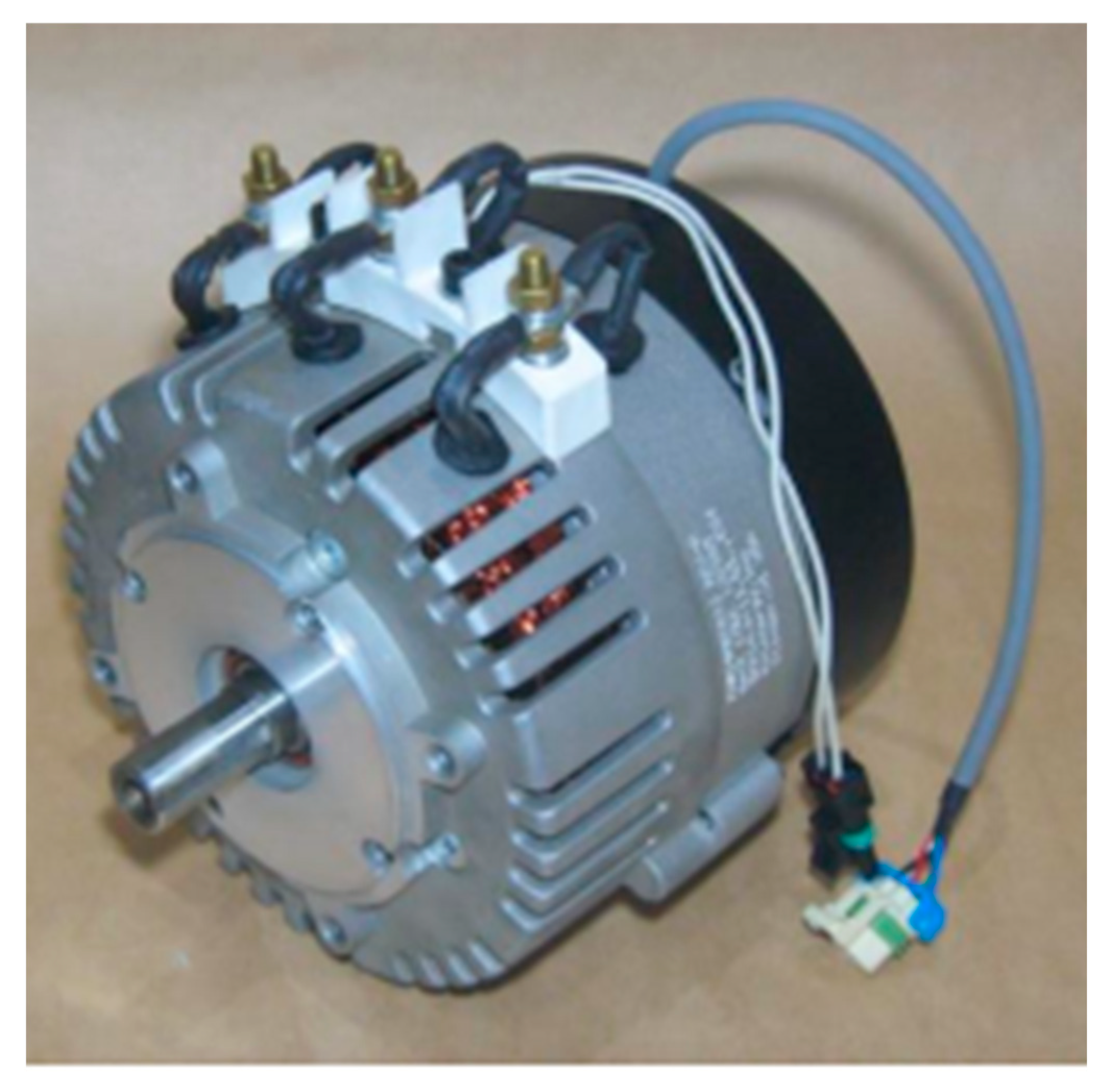
| Drive voltage | DC 24–96 V |
| Maximum current | 550 A |
| Maximum rotation speed | 5000 rpm (no load) |
| Maximum output | 30 kW (DC 96 V) |
| Maximum torque | 90 Nm |
| Continuous output | 12 kW (DC 96 V) |
| Continuous current | 180 A |
| Continuous efficiency | 92% |
| Continuous rotation speed | 3000 rpm |
| Mass | 15.9 kg |
| Poles | 4 (magnet 8) |
| Cooling method | Air-cooling forced-fan system |
| −50% | −40% | −30% | −20% | −10% | 0% | +10% | +20% | +30% | +40% | +50% | |
|---|---|---|---|---|---|---|---|---|---|---|---|
| P term | 0.25 | 0.3 | 0.35 | 0.4 | 0.45 | 0.5 | 0.55 | 0.6 | 0.65 | 0.7 | 0.75 |
| I term | 0.45 | 0.54 | 0.63 | 0.72 | 0.81 | 0.9 | 0.99 | 1.08 | 1.17 | 1.26 | 1.35 |
| D term | / | / | / | / | / | 0.01 | / | / | / | / | / |
Disclaimer/Publisher’s Note: The statements, opinions and data contained in all publications are solely those of the individual author(s) and contributor(s) and not of MDPI and/or the editor(s). MDPI and/or the editor(s) disclaim responsibility for any injury to people or property resulting from any ideas, methods, instructions or products referred to in the content. |
© 2025 by the authors. Licensee MDPI, Basel, Switzerland. This article is an open access article distributed under the terms and conditions of the Creative Commons Attribution (CC BY) license (https://creativecommons.org/licenses/by/4.0/).
Share and Cite
Yamada, H.; Kobayashi, M.; Ebashi, Y.; Kasamatsu, S.; Kobayashi, I.; Kuroda, J.; Uchino, D.; Ogawa, K.; Ikeda, K.; Kato, T.; et al. Basic Study on Operation Control Systems of Internal Combustion Engines in Hybrid Small Race Cars to Improve Dynamic Performance. Vehicles 2025, 7, 41. https://doi.org/10.3390/vehicles7020041
Yamada H, Kobayashi M, Ebashi Y, Kasamatsu S, Kobayashi I, Kuroda J, Uchino D, Ogawa K, Ikeda K, Kato T, et al. Basic Study on Operation Control Systems of Internal Combustion Engines in Hybrid Small Race Cars to Improve Dynamic Performance. Vehicles. 2025; 7(2):41. https://doi.org/10.3390/vehicles7020041
Chicago/Turabian StyleYamada, Hayato, Masamune Kobayashi, Yusuke Ebashi, Shinobu Kasamatsu, Ikkei Kobayashi, Jumpei Kuroda, Daigo Uchino, Kazuki Ogawa, Keigo Ikeda, Taro Kato, and et al. 2025. "Basic Study on Operation Control Systems of Internal Combustion Engines in Hybrid Small Race Cars to Improve Dynamic Performance" Vehicles 7, no. 2: 41. https://doi.org/10.3390/vehicles7020041
APA StyleYamada, H., Kobayashi, M., Ebashi, Y., Kasamatsu, S., Kobayashi, I., Kuroda, J., Uchino, D., Ogawa, K., Ikeda, K., Kato, T., Liu, X., Endo, A., Peeie, M. H. B., Narita, T., & Kato, H. (2025). Basic Study on Operation Control Systems of Internal Combustion Engines in Hybrid Small Race Cars to Improve Dynamic Performance. Vehicles, 7(2), 41. https://doi.org/10.3390/vehicles7020041