Abstract
With the increasing complexity of automated driving features, it is crucial to adopt innovative approaches that combine hardware and software to validate prototype vehicles in the early stages of development. This article demonstrates the effectiveness of a Vehicle-in-the-Loop (ViL) testbed in conducting dynamic tests of vehicles equipped with highly automated driving functions. The tests are designed to replicate critical driving scenarios from real-world environments on the ViL testbed. In this study, the Apollo platform is utilized to develop an automated driving function that can perceive the surrounding traffic in a virtual environment and generate feasible trajectories. This is achieved with the help of a multibody simulation platform. The control commands from the simulated driving function are then transmitted to the real vehicle to execute the planned action. The results demonstrate that critical traffic scenarios can be replicated more safely and repeatedly on the ViL testbed. Meanwhile, the Apollo-based driving function can effectively and comfortably cope with critical scenarios. Importantly, this study marks a significant milestone for the Apollo platform as it is implemented in a real-time system and tested on a ViL testbed.
1. Introduction
As automotive electrical and electronic technology advances, the complexity of automotive network topologies increases, necessitating real-world vehicle testing to optimize and validate ECU (electronic control unit) functionality. With the rising demand for Highly Automated Driving (HAD), validating the relevant system presents a significant challenge. It requires complete vehicle and ECU network coverage while ensuring the safety and efficiency of verification procedures. Thus, scenario-based proving-ground tests are no longer sufficient as they cannot provide the complex and dynamic environment necessary for comprehensive validation. Simulated scenario-based validation has emerged as a dominant solution, known as X-in-the-loop (XiL), and is used throughout the automotive development process. The authors of [1] provide a detailed presentation of simulation methods for each stage of the V-model. They suggest that X-in-the-loop (XiL), hardware-in-the-loop (HiL), driver-in-the-loop (DiL), and vehicle-in-the-loop (ViL) solutions are the most comprehensive solutions for software decisions, controller actuation and sensor perception validation of advanced driver assistance systems (ADAS). However, the HiL system has significant maintenance and modification requirements and often uses non-mass-produced wiring harnesses, resulting in electromagnetic interference issues. DiL evaluates vehicle-human interaction and is suitable for assessing ADAS function and comfort and driver reaction. ViL bridges the gap between all previous solutions and enables integrated vehicle testing in a virtual environment.
Innovation in ViL technology has been ongoing for over two decades since the pioneering solution provided by TNO Automotive [2]. In the current state of the art, ViL-based testing approaches are diverse. Despite the long-standing development of ViL technology, there have been limited reviews or surveys conducted on relevant applications. A classification system is proposed based on the implemented technology of testing to better illustrate the current state of the art, as below:
- Closed-Area Testing: In contrast to open-road testing, closed-area testing is considered a safer alternative. Generally, a GPS-equipped test vehicle drives within a test field and maps its position to the simulation environment in real-time [3]. In the context of ADAS testing, the sensory information generated by the simulated scenario is transmitted in a suitable format to the relevant ECUs or real sensors on the test vehicle to trigger the ADAS functions [4]. As a result, the real-time system must perform optimally and is subdivided into a cloud-based system and an on-board real-time system. For the former, the back-end achieves remote control of the vehicle through communication technology (e.g., LTE-V or 5G) [5,6,7]. However, due to the ease of integration, the majority of the technical implementation is carried out using the on-board real-time system. The in-vehicle system achieves synchronization between the road logic, traffic scenarios and the vehicle’s position, thereby enabling the generation of synthetic sensory data that can trigger actual sensors and elicit appropriate reactions from real vehicles [8,9,10]. Despite the wide usage of closed-area testing, it is not without its limitations. One such limitation is the need for a substantial investment in a large open area. Additionally, high dynamic testing can still pose hazards, and the vehicle under test (VUT) trajectory remains uncontrollable [11].
- Chassis Dynamometer Testing: To compensate for the huge waste of space in closed-area testing and to ensure a certain degree of high dynamic testing, a roller testbed test has been used in several studies. This is essentially a rolling road that measures the power output of the engine while the vehicle’s wheels are turning. For example, a series of groundbreaking investigations are presented in [2,12]. Subsequently, the use of simulation software to create a virtual environment was demonstrated to be a more efficient approach for validation in [13,14,15]. A co-simulation framework has been proposed to enhance the simulation scenario, enabling sensor stimulation on the testbed [16,17]. Although this type of bench was initially designed for emission tests, it has been extended to validate ADAS and can facilitate sensor stimulation due to its cost-effectiveness.
- Powertrain Testbed Testing: A roller testbed is no longer sufficient for achieving highly dynamic manoeuvres; hence, the powertrain testbed was introduced. Powertrain setups connect each wheel hub to a dyno simulating driving resistance at each wheel. To achieve comparable results with a rolling test rig, an additional rolling resistance simulation and an accurate tire simulation are required. For example, a distinctive feature of the test bench described in [18,19] is the integration of the alignment of torque simulation units, which employ wheel actuators to generate the corresponding aligning torque through a mechanical connection. The KS-R2R (road-to-rig) [20] technology differs from current approaches in that it employs complete wheel models instead of solely relying on tire models [21,22]. These models utilize torque as input and speed as an output, aligning more closely with the natural sequence of cause and effect. In the field of ADAS testing, a common approach is to use sensor stimulation as a solution, which has been widely adopted in many works [18,21,23,24,25]. In contrast to previous approaches that utilized sensor stimulation for ADAS validation, [22] provides an abstract representation of real sensors and ADAS functionality. This supports the development of ADAS functionality by demonstrating its feasibility in prototype vehicles during the functional concept phase. Overall, the powertrain testbed is not only capable of achieving highly dynamic manoeuvres but is also highly adaptable to the simulation environment, enabling the validation of ADAS functions and supporting early-stage concept development.
This study involves the development of a digital twin-based simulation environment which emulates real-life traffic scenarios in a virtual setting. A key aspect of the research is the successful implementation of the Apollo automated driving platform in a real-time system and its application on the ViL bench.
The paper is organized as follows: Section 2 provides an overview of the system, including the simulation configuration on the ViL testbed. Section 3 explains how the integration of the vehicle under test is performed on the ViL testbed. Section 4 focuses on the implementation of the Apollo platform on the real-time system. To demonstrate the Apollo functionality on the ViL testbed, the results of test cases are presented in Section 5. Furthermore, the experimental finds are discussed in Section 6. Finally, Section 7 summarizes the main findings of the paper.
2. System Design
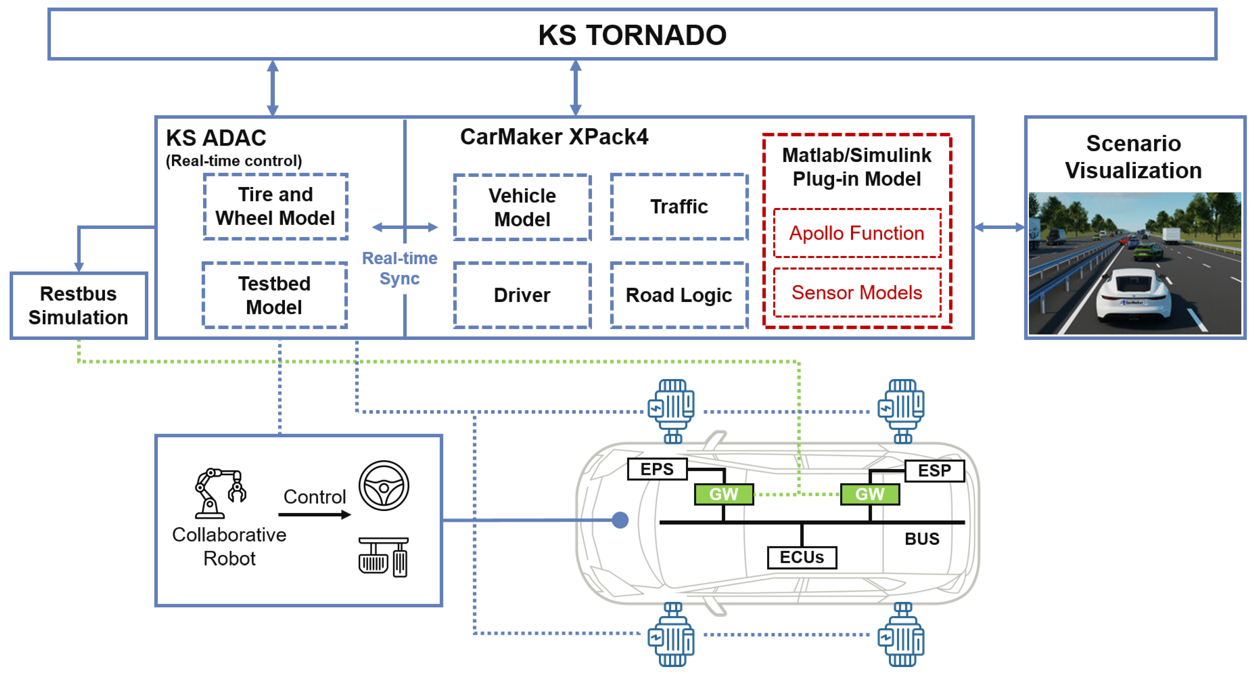
The ViL simulation system comprises two main components: a simulation platform and a vehicle under test. For the simulation part, KS Tornado (automation software from KS engineers) [26] acts as the main GUI, which interfaces with Carmaker from IPG Automotive and the real-time system KS ADAC (Advanced Data Acquisition and Control), which controls the KS-R2R testbed. The virtual vehicle environment inclusive of the vehicle, traffic scenario and road model is built in CarMaker from IPG Automotive and the visualization of virtual scenarios is also supported. Moreover, vehicle dynamics, sensor models and Apollo functions are integrated into CarMaker by utilizing S-functions and APIs in Simulink. The resulting model is then translated into C-code and embedded into the Xpack4 real-time system from IPG Automotive, which is capable of processing data at a rate of 1 kHz. Additionally, the employed mathematical models for loaded tires and the testbed are implemented in KS ADAC, which runs at a frequency of 5 kHz. It is important to note that the Testbed model is solely employed for offline simulations and does not encompass the online tests discussed in this paper. The EtherCAT technology [27] achieves real-time performance and topology flexibility between ADAC and Xpack4 to enable a co-simulation system.
Eventually, the vehicle under test (VUT) is fixed on the KS-R2R testbed using special testbed wheels with lead-through shafts, and a driving robot manipulates the measured quantities to match the driving manoeuvre preset in the simulation according to the KS ADAC control commands. Meanwhile, the real-time dynamics and operational status of the VUT on the testbed can also be transmitted back to CarMaker via KS-ADAC, allowing them to be read in CarMaker. This enables the virtual simulation scenario to reflect the actions and reactions of the actual VUT, thus creating a closed-loop system. The architecture of the entire ViL system is elaborated in Figure 1. Therefore, the introduction of subsequent sections all revolve around this basic ViL architecture. Section 3.1 of this study presents the introduction of the Restbus Simulation (RBS) for the testbed, focusing on its implementation and functionality. Section 3.2 provides details on the configuration and setup of the testbed for conducting the simulations. The successful implementation of the sensor model is demonstrated in Section 4.1, while Section 4.2 showcases the successful integration and operation of the Apollo function within the simulation environment. Lastly, Section 4.3 introduces the virtual scenario that serves as the case study for this research.
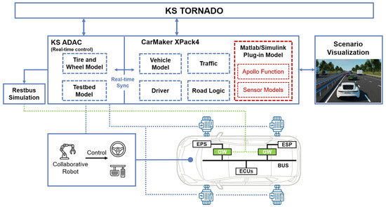
Figure 1.
KS-R2R testbed with full vehicle.
3. Vehicle-in-the-Loop Testbed
The modified VUT on the testbed requires a novel powertrain bench to achieve highly dynamic manoeuvres and reduce the simulation-to-reality gap. Consequently, to adequately satisfy our testing prerequisites, it is crucial to undertake modifications to the vehicle bus system. Furthermore, the novel testbed offers the possibility of conducting authentic on-road driving scenarios on the engine, powertrain, and tire dynamics.
3.1. Vehicle under Test
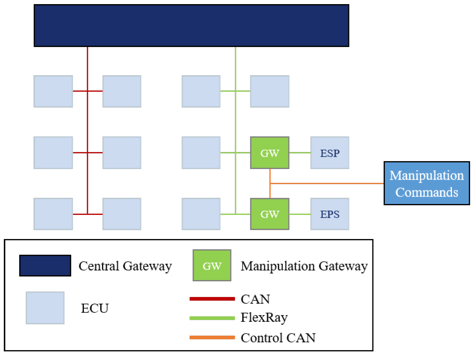
To conduct ViL testbed simulations, modifying the vehicle to adapt to the unique testing environment is imperative. This is primarily due to the conflict that arises between the simulation environment and the real-world sensor measurements when the vehicle is stationary on the test bench while the four-wheel motors of the powertrain testbed drive the vehicle. To ensure accurate simulation of the vehicle’s response to various virtual environmental conditions, modifications to the vehicle and its components are necessary, which should reflect the expected behaviour of the vehicle in a dynamic environment. In this study, we develop an RBS system (see Figure 2) by manipulating various vehicle bus signals, which enables us to control the vehicle’s functions electronically, thus allowing us to conduct tests in a controlled environment. To facilitate lateral control of the vehicle while conducting simulation scenarios on the testbed, the manipulation of the EPS (electric power steering) steering signal requires the utilization of a manipulation gateway, as the physical steering mechanics are not applicable. This enables us to defeat the plausibilization mechanisms built into the ECUs by manipulating various vehicle bus signals, such as steering angle, yaw rate, etc., according to the driving scenario, ultimately driving complex scenarios without physically moving the steering mechanism. Thus, the illusion of the vehicle actually steering is created. Meanwhile, we consider other vehicle dynamic factors, such as acceleration, yaw and roll angles generated during steering and modify them based on the vehicle dynamics model from IPG CarMaker. These modified signals by the manipulation gateway are then sent to the ESP (electronic stability program) for proper control and coordination during the simulation. In our simulation framework, it is crucial to ensure that the dynamics information generated by the virtual vehicle model in CarMaker is accurately reflected in the real vehicle. Therefore, the gateways responsible for data transmission retrieve the relevant signals from the simulation in real-time and modify them on the FlexRay bus to align with the desired test conditions.
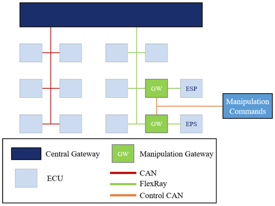
Figure 2.
Electrical/electronic architecture of the vehicle under test with signal manipulation for testing and simulation purposes.
3.2. Testbed Integration
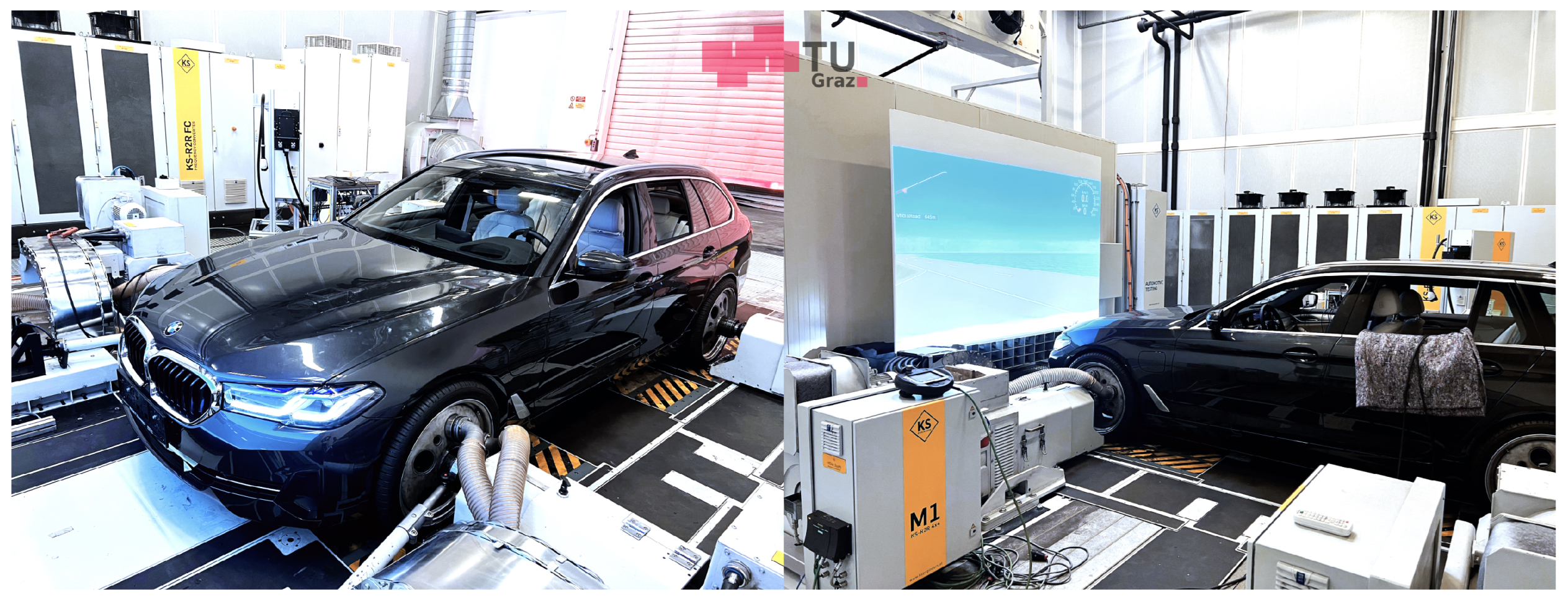
The research conducted by [21,22] enables the integration testbed configuration to allow for the complete vehicle to be mounted, as depicted in Figure 3. Constant-velocity joint shafts are used instead of the original vehicle wheels to connect the wheel hubs to the dynos. The wheels depicted in Figure 3 are specifically designed for the testbed and are equipped with lead-through shafts and bearings with no rotational capability. Additionally, Figure 3 provides a visual representation of the VUT positioned on the testbed, offering an overview of the setup’s appearance. These wheels facilitate typical pitching movements of the vehicle during the acceleration and braking phases. The patented wheel plates placed under the testbed wheels prevent unrealistic loads resulting from changes in the track width during the pitching movements.
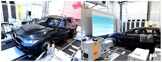
Figure 3.
Integration testbed with the full vehicle.
In order to replicate the same stresses on the powertrain as experienced on actual roads, wheel models (including tire models) are used to determine the speeds of the wheels based on the measured torques of the side shafts, which then interact with the virtual vehicle model in CarMaker. Next to the measured torque, the brake torque from a virtual brake model in CarMaker can also be considered for calculating the wheel speed, thus allowing different levels of details for vehicle parameterization. These models are computed in real-time on the testbed, and the resulting wheel speeds are utilized as reference values for speed control [28]. The KS-R2R technology differs from existing concepts as it employs complete wheel models that take torque as an input and produce speed as an output. The torques and speeds on the side shafts are measured within a single control cycle. The wheel models use these torques along with values from the virtual vehicle model in CarMaker, such as the normal force and velocity in the tire-road contact point, to calculate the wheel speeds. These calculated values then serve as setpoint values for the speed controllers, which trigger pulses for the frequency converter. The KS-R2R concept offers the advantage that the moment of inertia of the wheel machines used in the testbed does not need to match the moment of inertia of the simulated wheels. This feature enables to accurately reproduce the loads on the testbed in terms of speed and torque, providing a road-realistic depiction. The use of a robust control scheme eliminates the need to adjust the control parameters for different test samples, resulting in minimum set-up time with a relatively simple parameter configuration.
4. Function and Environment Simulation
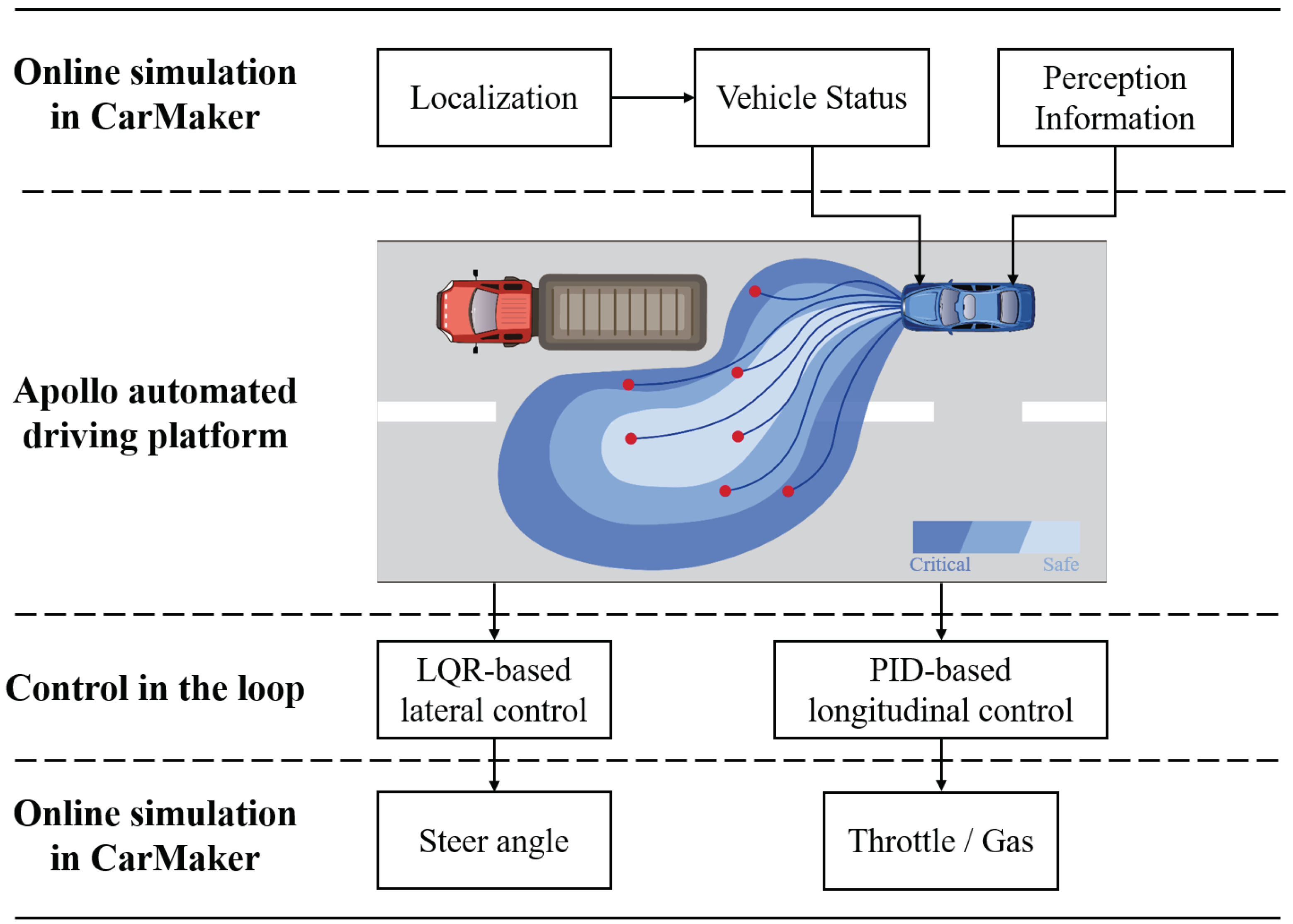
CarMaker from IPG Automotive has been developed to provide a comprehensive simulation environment. The virtual environment is designed to mimic real-world action, and any physical reaction that impacts the vehicle of interest in the simulation is extracted and passed on to the ViL testbed. This enables virtual driving behaviour to be applied to the VUT, providing a valuable tool for testing and validation. In order to implement a HAD function that should be tested, we integrated the open-source Apollo platform along with a simulation of the perception sensors [29]. The completeness simulation framework is depicted in Figure 4. CarMaker provides a realistic virtual environment for modelling various aspects of driving, including vehicle dynamics, traffic behaviour, and surrounding objects. This allows us to develop a perception model for detecting surrounding traffic introduced in Section 4.1. Additionally, the synchronized real-time system built by KS ADAC and IPG Xpack4 enables feedback of the VUT’s driving status. Through the CarMaker simulation, the ego car’s position can be localized, and its driving status can be analysed. This simulation information serves as input to the Apollo function illustrated in Section 4.2, where the path planning algorithm reacts to dynamic traffic objects. Finally, control signals generated by Apollo are then passed to the VUT on the bench to execute the corresponding control commands.
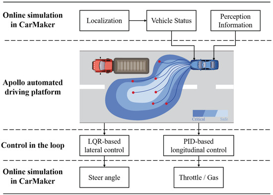
Figure 4.
Structure of Apollo platform in the simulation.
4.1. Perception Model
The perception module in the framework is responsible for processing sensor data from multiple sensors and using that data to understand the vehicle’s environment in real time. Given the high computational requirements for processing sensing data, our study utilizes only radar as the primary sensing sensor. This includes identifying and tracking vehicles. The perception module is a critical component of the automated driving system, as it provides the vehicle with the situational awareness it needs to make safe and effective driving decisions. The authors of [1] present a classification of sensor models based on the V-model process from the perspective of the system integrator. With the rise of over-the-air (OTA) technology, the technical model can be applied to the ViL testbed. It is able to generate a modulated signal that can stimulate the onboard radar without requiring an actual physical object to be present. For sensor stimulators, the primary issue is the lengthy preparation time needed for calibration, which also entails more costly investment in equipment. Meanwhile, during the early stage of the system development cycle, the initial prototype sensor samples may not be mature yet. Therefore, it is not suitable to stimulate the sensor hardware directly. To facilitate development in the early stages and address the immaturity of the prototype hardware issues, functional models are more appropriate for use.
The principle of the functional model has been described in [1]. This kind of model neglects the internal signal processing and sensing algorithms of sensors and, instead, concentrates on the uncertainty of sensor detection behaviour and sensing results. A method for modelling radar based on a mixture density network (MDN) was introduced in our previous study [29]. The approach focuses on learning the probability density function of the radar sensor measurements using a neural network model. This allows for the prediction of the distribution of possible measurement values, rather than just a single-point estimate. By ignoring the internal signal processing processes and sensing algorithms of the sensor, the approach simplifies the modeling process and saves computing power, while maintaining a balance between computational efficiency and accuracy. To improve the accuracy of sensor modelling and consider sensor performance under different weather conditions, a large-scale measurement campaign was conducted and is described in [30]. The MDN-based sensor model is trained using the data collected during this measurement and is subsequently used in the current configuration of the ViL testbed simulation environment.
4.2. Apollo Platform Integration
Apollo is an open-source platform for HAD developed by Baidu, a Chinese multinational technology company. After years of iterations, the architecture of Apollo is introduced in [31,32], which includes a range of modules, including perception, planning, control, and simulation, as well as tools for data collection and processing. The flexibility and adaptability of this algorithm make it particularly interesting for multiple applications of the level 4 autonomous Robotaxi that will be launched in China in forthcoming years and whose testing has already started in Beijing [33]. The Apollo project is currently implemented using the widely used robot operating system (ROS) software framework. However, to enhance the reusability of the project, the C++ code-based Apollo is translated into a Simulink model in our work.
The intermediate layer depicted in Figure 4 provides a depiction of the operational flow of the Apollo system. In the first layer of online simulation using CarMaker, the road logic, virtual traffic scenarios, and vehicle model are integrated into the simulation framework. This enables the collection of real-time data on the driving status and localization of the ego vehicle. To predict the behaviour of surrounding traffic, the virtual vehicle is equipped with trained sensor models. The information captured by these sensors is then utilized and transferred to subsequent algorithmic calculations for further analysis and decision-making processes. Apollo performs motion planning by obtaining information on surrounding obstacles from the upper layer and the vehicle’s own motion state. As trajectory planning is the most computationally intensive part, it is decoupled from path and velocity planning in Apollo. Therefore, the power-consuming EM planner (see [34]) is replaced with a lattice planner (see [35]) to achieve a more stable and smooth planning process. The basic principle involves scattering path points ahead of the vehicle and connecting discrete points with fifth-order polynomials to construct a grid. The path cost for each edge in the graph is calculated using the overall objective function, which is a linear combination of smoothness, obstacle avoidance, and reference line cost. After calculating the cost of each possible path and distinguishing them, as shown in Figure 4, with different colours, the path with the minimum cost and the corresponding speed is selected and sent to the control module. Application of this concept enables more reasonable decisions to be made for overtaking or following while also planning for trajectory and speed.
In [36], the authors present an introduction to the lateral and longitudinal control strategy employed in Apollo. Specifically, the linear quadratic regulator (LQR) controller is used to generate the optimal steering command based on the current vehicle state and planned trajectory. The use of an LQR controller for lateral control ensures that the vehicle can accurately follow the desired trajectory while maintaining stability and smoothness in the control input. Additionally, the longitudinal controller in Apollo utilizes a two-stage proportional–integral–derivative (PID) controller for station and speed control, as well as a throttle/brake calibration table. It receives planned trajectories, localization information, and vehicle motion data to generate appropriate throttle and brake commands for the vehicle.The displacement PID controller takes the desired and current position information as inputs and forwards the speed compensation to the subsequent speed PID controller. At this stage, the speed and planned velocity compensation serve as inputs for generating acceleration compensation, which is passed through calibration tables. Overall, The trajectory controller in the system is responsible for generating steering angle commands to the real vehicle that maintain the vehicle’s position on the planned path, while the speed controller regulates the vehicle’s speed by modulating the throttle and brake pedals in percentage activity.
4.3. Driving Scenario
The development of simulation scenarios aims to replicate real-world driving situations for testing purposes, which requires a digital-twin-based simulation. To achieve this, GPS (Global Positioning System) data from the dataset is converted into relative metric coordinates, which allows for the extraction of necessary trajectory data. In [37], the CarMaker C-code interface was intended to be modified to enable the exact following of recorded trajectories; however, the vehicle under test could only replicate position and lacked dynamic information. Hence, ScenarioRRR, an extended toolbox of IPG Automotive, is used in conjunction with the converted GPS routes to create a ready-to-play test run in CarMaker. The primary advantage of creating simulation scenarios is to replicate the trajectory and vehicle dynamics information of the ego car, resulting in a cost-effective, time-saving, safer, and reproducible way to test critical cases. Therefore, evasive lane change (Section 5.1) and preventing collision (Section 5.2), are selected to demonstrate the efficacy of Apollo on the testbed.
5. Case Studies
The ViL testbed allows for highly accurate and repeatable testing of ADAS functions in a controlled and repeatable environment. It also provides greater flexibility for function integration and sensor model implementation. By creating digital twin-based test scenarios, the ViL testbed can evaluate critical cases in a safer manner, reducing the risks associated with real-world testing. Furthermore, the reproducibility and comprehensive data collection capabilities of the testbed enable a more accurate and detailed analysis of the performance of ADAS functions.
5.1. Evasive Lane Change
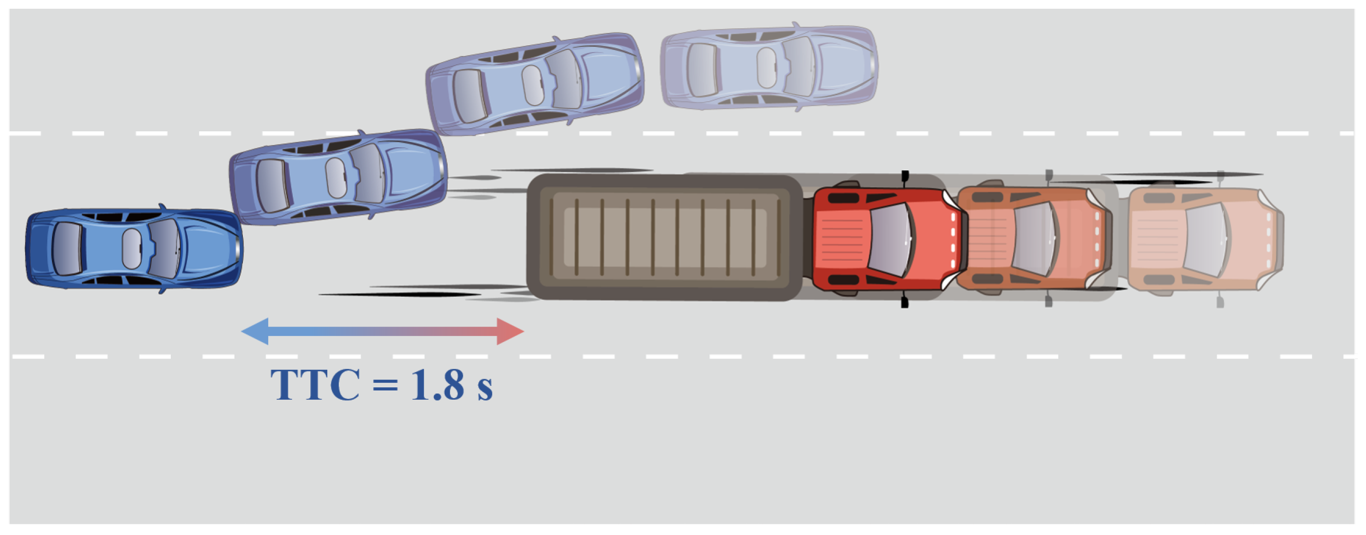
The HighD dataset is a comprehensive traffic dataset designed for autonomous driving research, comprising high-resolution synchronized sensor data captured over 60 h of traffic scenarios and encompassing 110,500 vehicles on a highway in Germany [38]. Wang et al. [39] proposed a method for filtering out safety-critical scenarios and applied it to the HighD dataset. Among the seven safety-critical scenarios identified through the proposed approach, we emphasise the left evasion case in our simulation. In [39], a detailed description is provided of this critical lane change scenario that is implemented in a simulation. In simpler terms, the critical left evasion case involves a situation where a truck in front suddenly slows down, forcing a fast-approaching car from behind to perform an evasive lane change to avoid a collision, as shown in Figure 5. In a real-world scenario, the human driver would make the lane change when the two cars’ time-to-collision (TTC) reaches 1.8 s. In this case, the trajectory and state of the front truck are incorporated into the simulation using CarMaker’s extended interface. Meanwhile, The ViL testbed is used to verify whether the VUT equipped with Apollo can successfully cope with this scenario when the lane change is triggered under the same conditions.
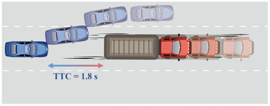
Figure 5.
Evasive lane change sequence.
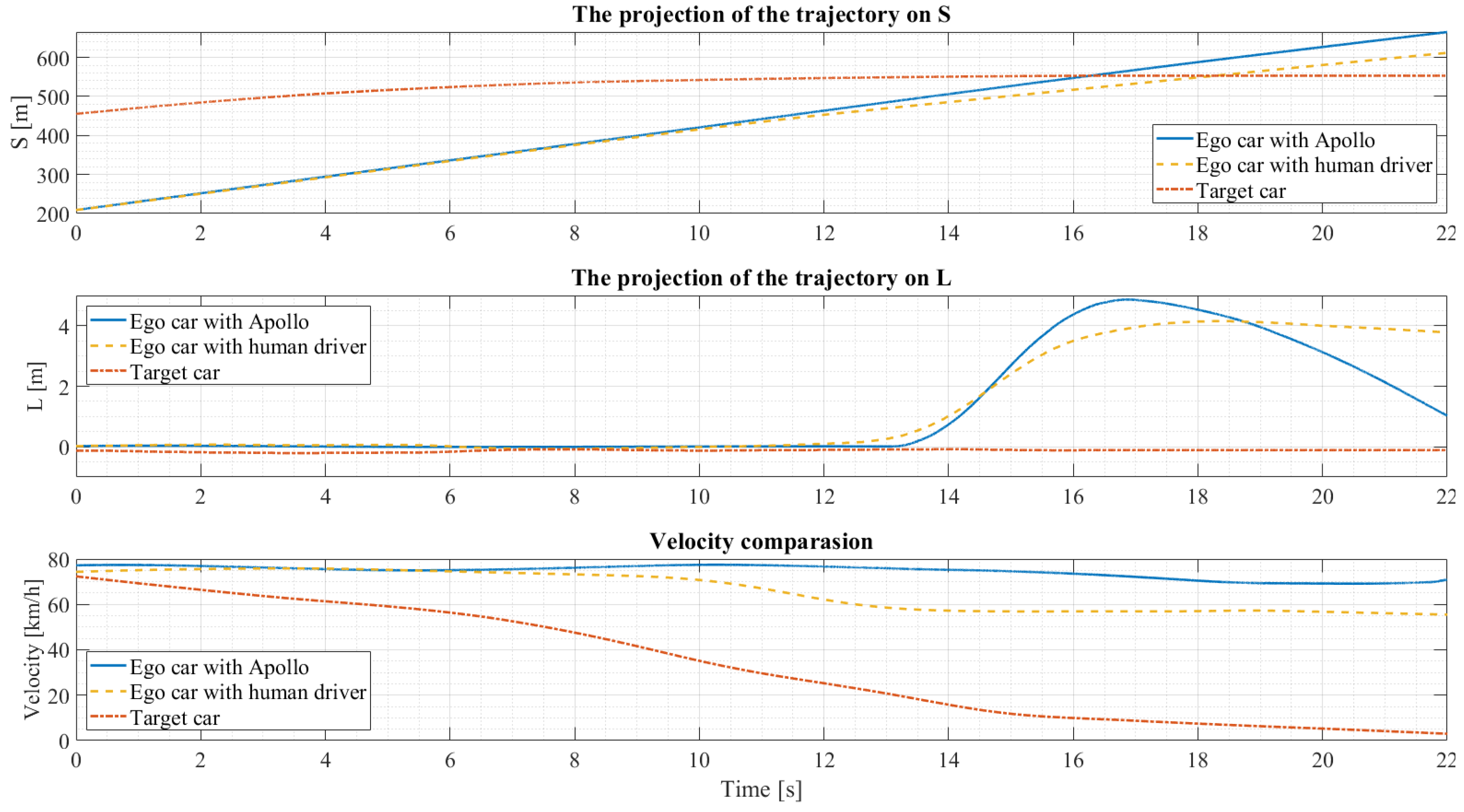
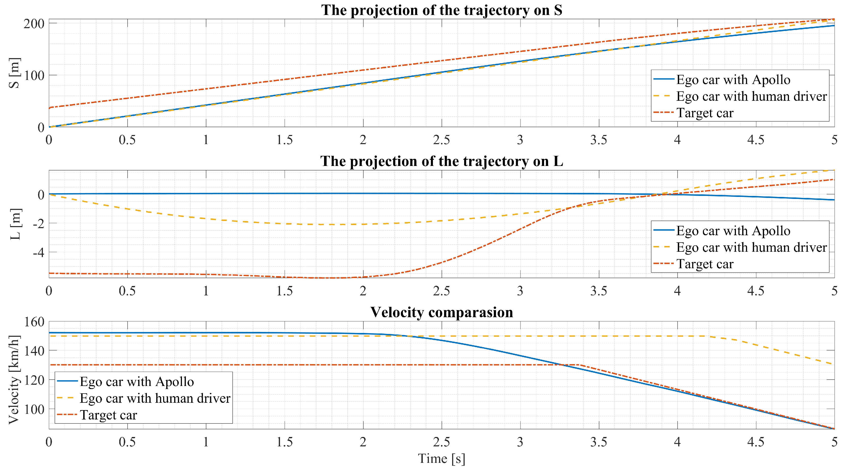
In order to reduce the intricacy of the trajectory analysis, subsequent analyses of the results employed the Frenet coordinate system, where S represent the longitudinal distance along the route, and L indicates the lateral deviation according to the reference line. The reference line for this system is established based on the centerline of the starting lane of the ego car. To analyze and compare the driving reaction of the Apollo automated driving system and a human driver in response to a target vehicle manoeuvre, the trajectories of the three entities are plotted in Figure 6. The identical analytical methodology is also implemented in Section 5.2.
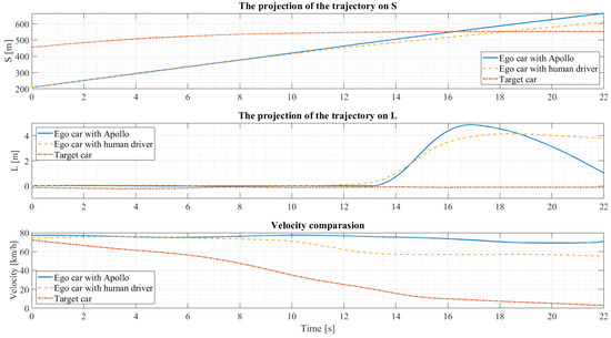
Figure 6.
Evasive lane change scenario: comparing the response of the Apollo automated driving system and a human driver to a target vehicle manoeuvre.
The simulation results of the trajectory in Figure 6, presented in the S-L coordinate, reveal that the Apollo-based driving function demonstrates driving behaviour comparable to that of a human driver before the 10-s mark, particularly in terms of longitudinal and lateral displacement. This similarity is achieved by setting the initial conditions in the test bench to match the driving conditions in a real-world scenario, providing a solid foundation for evaluating subsequent Apollo decisions. Between the time interval of 10 to 13 s, a noticeable difference arises in the decision-making of the human driver, who opts to decelerate from 77 km/h to approximately 60 km/h in response to the presence of the truck ahead. In contrast, the Apollo-based driving function maintains a predetermined cruising speed during the same time interval and does not proactively respond to the presence of the forward truck. However, the Apollo automated driving system and the human driver exhibit similar driving behaviour in response to a target car manoeuvre, with a lane change after 13 s. However, the decisions of the two diverge after 16 s, with the human driver preferring to remain in the new lane. In contrast, the Apollo system, guided by a single-reference line, actively returns the vehicle to the original lane after completing the lane change, which causes a 1 m offset in the L-direction trajectory due to the comfort weight constraint. Additionally, the velocity plot shows that the human driver decelerates significantly in response to a sudden speed reduction of the car in front, while the Apollo system only slightly decelerates at the beginning of the lane change to maintain comfort. Nonetheless, the final simulation results confirm that the automated driving system can effectively handle emergency avoidance scenarios. However, further calibration and planning strategies are required to enhance the system’s ability to learn from human driving behaviour. The time interval between 15 and 18 s is particularly notable for assessing lateral controllability. Excessive lateral displacement has the potential to mitigate risks, but it may also introduce discomfort for passengers. This aspect warrants further investigation in future research endeavours.
5.2. Preventing Collisions
This study of preventing collision uses the CEDATU (Central Database for In-Depth Accident Study) road accident database [40,41] as a source of data. The CEDATU includes about 4500 accidents that resulted in either personal injury (fatal, severe or minor) or property damage only. This scenario is a typical example of high-dynamic situations and is, thus, chosen to test the effectiveness of Apollo’s emergency response strategy during high-speed driving conditions. The overall collision scenario is given in Figure 7. The collision occurred during nighttime on a dry road with favourable weather conditions. The target vehicle is travelling at 130 km/h, while the ego vehicle is travelling at 150 km/h, exceeding the speed limit ( 130 km/h). The target vehicle is initially in the right lane, while the ego vehicle is in an adjacent lane. Subsequently, the target vehicle changes lane, after which it abruptly decelerates from 130 km/h to 86 km/h for an unknown reason. The driver of the ego vehicle attempted to avoid a collision by applying emergency brakes. Unfortunately, the driver of the target vehicle is not wearing a seat belt and is ejected from the vehicle, resulting in fatal injuries. The accident is caused by high-speed driving with a delayed reaction time of the ego car’s driver. Even with a typical human driver reaction time of s according to [42,43,44], the ego car would not have been able to prevent the collision after the target vehicle changed lanes. Therefore, the use of the Apollo platform to develop a highway chauffeur function to address such scenarios appears to be reasonable.

Figure 7.
Pre-crash sequence.
The present study aims to validate Apollo’s decision on speed planning for a high-speed collision scenario. In this real accident scenario, the human driver’s lack of timely reaction to potential danger often leads to collisions. Figure 8 shows the motion process of the target car five seconds before the collision. During the initial four-second period, both the trajectory of the Apollo-based driving function and the human driver exhibit comparable behaviour. This alignment of trajectories serves as a suitable starting point for testing subsequent manoeuvres. The velocity profile indicates that the human driver realized the need to slow down only s before the collision, which was already too late. Such accidents are often caused by distraction of the driver’s attention. The analysis of the trajectory in the L-direction shows that the human driver exhibited abnormal driving behaviour characterized by lane departure during the time interval of 0–4 s before the occurrence of the accident. In contrast, the Apollo-based driving function effectively maintained the vehicle’s position in the middle of the road due to the proper weighting of the centre line constraints of the lane. Additionally, the target car begins to move towards the left lane from s onwards. In contrast, Apollo’s speed planning module predicted the target car’s motion in the adjacent lane and initiated a slow deceleration to adjust the distance between the cars. When the front car invaded the ego car lane at 3 s, the ego car decelerated at a rate of approximately m/s2 to avoid a collision. At the end of 5 s, a safe distance of 10 m is maintained from the target car, as shown in the S-direction plot. This demonstrates the benefit of automated driving, which continuously monitors the road and ensures safety, unlike a human driver prone to distraction and delayed reaction to potential dangers.
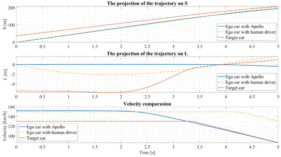
Figure 8.
Preventing collisions scenario: comparing the response of the Apollo automated driving system and a human driver to a target vehicle manoeuvre.
6. Discussion
In this study, we introduce and test an Apollo-based HAD function on the ViL testbed, marking a significant milestone in implementing this HAD function within a real-time simulation system. Two scenarios are successfully replicated, rear-end collision prevention and evasive lane change, on the testbed, showcasing the potential of digital twin-based simulation testing. However, it is essential to note that the current Apollo system lacks the comfort aspect exhibited by human drivers, particularly in the case of evasive lane change, where human drivers demonstrate better speed control and lane change path comfort. Calibration of the Apollo system parameters emerges as a potential avenue for future research. Nonetheless, the excellent performance in rear-end collision prevention highlights the system’s reliable response to critical situations. The reliance on sensor perception allows for early detection of potential risks, with Apollo reacting appropriately. Overall, the proposed simulation framework depicted in Figure 1 exhibits robust reliability in executing Apollo-based driving functions and offers flexibility for future extensions. The ViL setup is able to replicate highly dynamic driving scenarios which cannot be replicated on public roads but also maybe not on proving grounds because of the high speeds which makes it complicated to maintain safety.
7. Conclusions
This study presents the development of a co-simulation framework to construct a complete vehicle simulation environment using a ViL testbed. The experimental results reveal that the inclusion of the complete vehicle within the simulation environment enhances the realism of the testing setup, thereby potentially facilitating future virtual homologation efforts, and HAD functions should be tested on the full vehicle level. The ViL testbed provides a viable option to balance virtual validation and real-world testing, which mitigates potential risks associated with public road testing. The successful re-engineering of the Apollo automated driving system and its implementation on the ViL bench showcases the possibility of testing future SAE Level 4 fuctions not yet implemented in the vehicle under test. This achievement validates the feasibility of running complex systems on real-time platforms. Furthermore, scenario-based simulations have demonstrated Apollo’s competence in responding to real-life hazardous situations, highlighting its potential to enhance road safety. This study emphasizes the significance of full vehicle testing and provides a reliable and safe testing platform for developing HAD functions.
In our future work, Apollo systems will continue to be optimized and enhanced, particularly by enhancing the trajectory planning module to better emulate human driver behaviour. Furthermore, the incorporation of more complex traffic flow scenarios to validate and test the efficiency of Apollo on the ViL testbed is intended.
Author Contributions
Conceptualization, H.L., V.P.M., E.T. and A.E.; methodology, H.L., V.P.M., E.T. and A.E.; software, H.L., V.P.M., E.T., L.W. and A.E.; validation, H.L., V.P.M., E.T., L.W. and A.E.; formal analysis, H.L., V.P.M., E.T., H.H., L.W. and A.E.; investigation, H.L., V.P.M., E.T., H.H., L.W. and A.E.; resources, H.L., V.P.M., E.T., H.H., L.W. and A.E.; data curation, H.L., V.P.M., E.T., L.W. and A.E.; writing—original draft preparation, H.L., V.P.M., E.T., L.W. and A.E.; writing—review and editing, H.L., V.P.M., E.T., L.W. and A.E.; visualization, H.L., V.P.M., E.T., L.W. and A.E.; supervision, A.E.; project administration, A.E. All authors have read and agreed to the published version of the manuscript.
Funding
Open Access Funding by the Graz University of Technology. This activity is part of the research project InVADE (FFG nr. 889349) and has received funding from the program Mobility of the Future, operated by the Austrian research funding agency FFG. Mobility of the Future is a mission-oriented research and development program to help Austria create a transport system designed to meet future mobility and social challenges.
Institutional Review Board Statement
Not applicable.
Informed Consent Statement
Not applicable.
Data Availability Statement
Not applicable.
Acknowledgments
We extend our gratitude to Minbo Tan and Vincent Wong for generously sharing their professional perspectives on the Apollo algorithm and their extensive engineering experience with us in the course of this research. Additionally, we thank Zhengguo Gu for his valuable internship support, which greatly contributed to the success of this project.
Conflicts of Interest
The authors declare that the research was conducted in the absence of any commercial or financial relationships that could be construed as a potential conflict of interest. Additionally, the authors declare that this study received funding from the Austrian research funding agency FFG within the scope of the research project InVADE. The funder was not involved in the study design, collection, analysis, interpretation of data, the writing of this article or the decision to submit it for publication.
References
- Magosi, Z.F.; Li, H.; Rosenberger, P.; Wan, L.; Eichberger, A. A Survey on Modelling of Automotive Radar Sensors for Virtual Test and Validation of Automated Driving. Sensors 2022, 22, 5693. [Google Scholar] [CrossRef] [PubMed]
- Verhoeff, L.; Verburg, D.; Lupker, H.; Kusters, L.J. VEHIL: A full-scale test methodology for intelligent transport systems, vehicles and subsystems. In Proceedings of the IEEE Intelligent Vehicles Symposium 2000 (Cat. No. 00TH8511), Dearborn, MI, USA, 5 October 2000; pp. 369–375. [Google Scholar]
- Bhadani, R.K.; Sprinkle, J.; Bunting, M. The cat vehicle testbed: A simulator with hardware in the loop for autonomous vehicle applications. arXiv 2018, arXiv:1804.04347. [Google Scholar] [CrossRef]
- Miquet, C. New test method for reproducible real-time tests of ADAS ECUs: “Vehicle-in-the-Loop” connects real-worldvehicles 12 with the virtual world. In 5th International Munich Chassis Symposium 2014: Chassis. Tech Plus; Springer: Wiesbaden, Germany, 2014; pp. 575–589. [Google Scholar]
- Che, X.; Li, C.; Zhang, Z. An Open Vehicle-in-the-Loop Test Method for Autonomous Vehicle; EasyChair: Manchester, UK, 2019. [Google Scholar]
- Fayazi, S.A.; Vahidi, A.; Luckow, A. A Vehicle-in-the-Loop (VIL) verification of an all-autonomous intersection control scheme. Transp. Res. Part C Emerg. Technol. 2019, 107, 193–210. [Google Scholar] [CrossRef]
- Gelbal, Ş.Y.; Tamilarasan, S.; Cantaş, M.R.; Güvenç, L.; Aksun-Güvenç, B. A connected and autonomous vehicle hardware-in-the-loop simulator for developing automated driving algorithms. In Proceedings of the 2017 IEEE International Conference on Systems, Man, and Cybernetics (SMC), Banff, AB, Canada, 5–8 October 2017; pp. 3397–3402. [Google Scholar]
- Tettamanti, T.; Szalai, M.; Vass, S.; Tihanyi, V. Vehicle-in-the-loop test environment for autonomous driving with microscopic traffic simulation. In Proceedings of the 2018 IEEE International Conference on Vehicular Electronics and Safety (ICVES), Bogota, Colombia, 14–16 November 2022; pp. 1–6. [Google Scholar]
- Drechsler, M.F.; Sharma, V.; Reway, F.; Schütz, C.; Huber, W. Dynamic vehicle-in-the-loop: A novel method for testing automated driving functions. SAE Int. J. Connect. Autom. Veh. 2022, 5, 367–380. [Google Scholar] [CrossRef]
- Chen, Y.; Chen, S.; Xiao, T.; Zhang, S.; Hou, Q.; Zheng, N. Mixed test environment-based vehicle-in-the-loop validation-a new testing approach for autonomous vehicles. In Proceedings of the 2020 IEEE Intelligent Vehicles Symposium (IV), Las Vegas, NV, USA, 19 October–13 November 2020; pp. 1283–1289. [Google Scholar]
- Ferguson, D.; Howard, T.M.; Likhachev, M. Motion planning in urban environments. In The DARPA Urban Challenge: Autonomous Vehicles in City Traffic; Springer: Berlin/Heidelberg, Germany, 2009; pp. 61–89. [Google Scholar]
- Verbürg, D.; van der Knaap, A.C.; Ploeg, J. Developing and testing intelligent vehicles. In Proceedings of the IEEE Intelligent Vehicle Symposium (IV’2002), Versailles, France, 18–20 June 2002; pp. 1–8. [Google Scholar]
- Gietelink, O.; Ploeg, J.; Schutter, B.; Verhaegen, M. Testing advanced driver assistance systems for fault management with the VEHIL test facility. In Proceedings of the 7th International Symposium on Advanced Vehicle Control, Arnhem, The Netherlands, 23–27 August 2004; pp. 579–584. [Google Scholar]
- Albers, A.; Düser, T. A new process for configuration and application of complex validation environments using the example of vehicle-in-the-loop at the roller test bench. In Proceedings of the ASME International Mechanical Engineering Congress and Exposition, Vancouver, BC, Canada, 12–18 November 2010; Volume 44489, pp. 807–816. [Google Scholar]
- Albers, A.; Düser, T. Implementation of a vehicle-in-the-loop development and validation platform. In Proceedings of the FISITA World Automotive Congress, Budapest, Hungary, 30 May–4 June 2010; Volume 2010. [Google Scholar]
- Solmaz, S.; Holzinger, F. A novel testbench for development, calibration and functional testing of ADAS/AD functions. In Proceedings of the 2019 IEEE International Conference on Connected Vehicles and Expo (ICCVE), Graz, Austria, 4–8 November 2019; pp. 1–8. [Google Scholar]
- Qin, Y.; Tang, A.; Jia, J.; Wan, L.; Zhao, H.; Long, Y. Research on Radiated Immunity Test Methods for ADAS Functions Considering Vehicle In-the-Loop. World Electr. Veh. J. 2022, 13, 211. [Google Scholar] [CrossRef]
- Diewald, A.; Kurz, C.; Kannan, P.V.; Gießler, M.; Pauli, M.; Göttel, B.; Kayser, T.; Gauterin, F.; Zwick, T. Radar target simulation for vehicle-in-the-loop testing. Vehicles 2021, 3, 257–271. [Google Scholar] [CrossRef]
- Rautenberg, P.; Kurz, C.; Gießler, M.; Gauterin, F. Driving Robot for Reproducible Testing: A Novel Combination of Pedal and Steering Robot on a Steerable Vehicle Test Bench. Vehicles 2022, 4, 727–743. [Google Scholar] [CrossRef]
- R2R Road to Rig—KS Engineers—ksengineers.com. Available online: https://www.ksengineers.com/en/Automotive-Testing/Testing-equipment/R2R-Road-to-Rig (accessed on 19 May 2023).
- Wipfler, M.; Pressl, B.; Piecha, P. Range Prediction with the Support of an Integration Test Bench. In Proceedings of the 43rd Internationales Wiener Motorensymposium, Vienna, Austria, 27–29 April 2022. [Google Scholar]
- Li, H.; Nalic, D.; Makkapati, V.; Eichberger, A.; Fang, X.; Tettamanti, T. A real-time co-simulation framework for virtual test and validation on a high dynamic vehicle test bed. In Proceedings of the 2021 IEEE Intelligent Vehicles Symposium (IV), Nagoya, Japan, 11–17 July 2021; pp. 1132–1137. [Google Scholar]
- Siegl, S.; Ratz, S.; Düser, T.; Hettel, R. Vehicle-in-the-Loop at Testbeds for ADAS/AD Validation. ATZelectron. Worldw. 2021, 16, 62–67. [Google Scholar] [CrossRef]
- Schyr, C.; Brissard, A. Drivingcube—A novel concept for validation of powertrain and steering systems with automated driving. In Advanced Vehicle Control AVEC’16; CRC Press: Boca Raton, FL, USA, 2016; pp. 79–84. [Google Scholar]
- Schyr, C.; Inoue, H.; Nakaoka, Y. Vehicle-in-the-Loop Testing-a Comparative Study for Efficient Validation of ADAS/AD Functions. In Proceedings of the 2022 International Conference on Connected Vehicle and Expo (ICCVE), Lakeland, FL, USA, 7–9 March 2022; pp. 1–8. [Google Scholar]
- Tornado Software Suite—KS Engineers—ksengineers.com. Available online: https://www.ksengineers.com/en/Automotive-Testing/Management-and-automation-tools/Tornado-Software-Suite (accessed on 19 May 2023).
- Jansen, D.; Buttner, H. Real-time Ethernet: The EtherCAT solution. Comput. Control. Eng. 2004, 15, 16–21. [Google Scholar] [CrossRef]
- Bauer, R. New Methodology for Dynamic Drive Train Testing; Technical Report, SAE Technical Paper; SAE: Warrendale, PA, USA, 2011. [Google Scholar]
- Li, H.; Kanuric, T.; Eichberger, A. Automotive Radar Modeling for Virtual Simulation Based on Mixture Density Network. IEEE Sens. J. 2022, 23, 11117–11124. [Google Scholar] [CrossRef]
- Li, H.; Bamminger, N.; Magosi, Z.F.; Feichtinger, C.; Zhao, Y.; Mihalj, T.; Orucevic, F.; Eichberger, A. The Effect of Rainfall and Illumination on Automotive Sensors Detection Performance. Sustainability 2023, 15, 7260. [Google Scholar] [CrossRef]
- Baidu. Apollo Auto. Available online: https://github.com/ApolloAuto/apollo.git (accessed on 26 September 2022).
- Wong, V. Automated-Driving-Control. Available online: https://github.com/VincentWong3 (accessed on 4 December 2022).
- Krolicki, K. Baidu, Pony.ai start driverless robotaxi tests in Beijing. Reuters, 30 December 2022. [Google Scholar]
- Fan, H.; Zhu, F.; Liu, C.; Zhang, L.; Zhuang, L.; Li, D.; Zhu, W.; Hu, J.; Li, H.; Kong, Q. Baidu apollo em motion planner. arXiv 2018, arXiv:1807.08048. [Google Scholar]
- Pivtoraiko, M.; Kelly, A. Efficient constrained path planning via search in state lattices. In Proceedings of the International Symposium on Artificial Intelligence, Robotics, and Automation in Space, Munich, Germany, 5–8 September 2005; pp. 1–7. [Google Scholar]
- Feng, M.; Zhang, H. Application of Baidu Apollo open platform in a course of control simulation experiments. Comput. Appl. Eng. Educ. 2022, 30, 892–906. [Google Scholar] [CrossRef]
- Magosi, Z.F.; Wellershaus, C.; Tihanyi, V.R.; Luley, P.; Eichberger, A. Evaluation Methodology for Physical Radar Perception Sensor Models Based on On-Road Measurements for the Testing and Validation of Automated Driving. Energies 2022, 15, 2545. [Google Scholar] [CrossRef]
- Krajewski, R.; Bock, J.; Kloeker, L.; Eckstein, L. The highD Dataset: A Drone Dataset of Naturalistic Vehicle Trajectories on German Highways for Validation of Highly Automated Driving Systems. In Proceedings of the 2018 21st International Conference on Intelligent Transportation Systems (ITSC), Maui, HI, USA, 4–7 November 2018; pp. 2118–2125. [Google Scholar] [CrossRef]
- Wang, C.; Popp, C.; Winner, H. Acceleration-Based Collision Criticality Metric for Holistic Online Safety Assessment in Automated Driving. IEEE Access 2022, 10, 70662–70674. [Google Scholar] [CrossRef]
- Tomasch, E.; Steffan, H. ZEDATU—Zentrale Datenbank tödlicher Unfälle in Österreich—A Central Database of Fatalities in Austria. In Proceedings of the 2nd International Conference on ESAR “Expert Symposium on Accident Research”, Hannover, German, 1–2 September 2006. [Google Scholar]
- Tomasch, E.; Steffan, H.; Darok, M. Retrospective accident investigation using information from court. In Proceedings of the Transport Research Arena Europe 2008 (TRA), Ljubljana, Slovenia, 21–24 April 2008. [Google Scholar]
- Burckhardt, M.; Burg, H.; Gnadler, R.; Schiemann, G. Die Bremsreaktionsdauer von Pkw-Fahrern. Der Verkehrsunfall 1981, 19, 224–227. [Google Scholar]
- Burckhardt, M.; Burg, H.; Gnadler, R.; Näumann, E.; Schiemann, G. Die Brems-Reaktionsdauer von Pkw-Fahrern. 1981. Available online: https://trid.trb.org/view/1043508 (accessed on 26 September 2022).
- Hugemann, W. Driver Reaction Times in Road Traffic. In Proceedings of the Annual EVU Meeting, Edinburgh, UK, 11–12 July 2002; Europäische Vereinigung für Unfallforschung und Unfallanalyse e.V.: Portorož, Slovenia, 2002. [Google Scholar]
Disclaimer/Publisher’s Note: The statements, opinions and data contained in all publications are solely those of the individual author(s) and contributor(s) and not of MDPI and/or the editor(s). MDPI and/or the editor(s) disclaim responsibility for any injury to people or property resulting from any ideas, methods, instructions or products referred to in the content. |
© 2023 by the authors. Licensee MDPI, Basel, Switzerland. This article is an open access article distributed under the terms and conditions of the Creative Commons Attribution (CC BY) license (https://creativecommons.org/licenses/by/4.0/).

