Abstract
Graph-based design languages have received increasing attention in the research community, because they offer a promising approach to address several major issues in engineering, e.g., the frequent manual data transfer between computer-aided design (CAD) and computer-aided engineering (CAE) systems. Currently, these issues prevent the realization of machine executable digital design processes of complex systems such as vehicles. Promising scenarios for urban transportation include an interconnection of mass transportation systems such as buses and subways with individual vehicles for the so-called “last mile” transport. For several reasons, these vehicles should be as small and light as possible. A considerable reduction in weight and size can be achieved, if such vehicles are tailored to the individual size, weight and proportion of the individual user. However, tailoring vehicles for the individual characteristics of each user go beyond a simple building set and require a continuous digital design process. Consequently, the topic of this paper is a digital design process of a self-balanced scooter, which can be used as an individual last-mile means of transport. This process is based on graph-based design languages, because in these languages, a digital system model is generated, which contains all relevant information about a design and can be fed into any simulation tool which is needed to evaluate the impact of a possible design variation on the resulting product performance. As this process can be automated by digital compilers, it is possible to perform systematic design variations for an almost infinite amount of parameters and topological variants. Consequently, these kinds of graph-based languages are a powerful means to generate viable design alternatives and thus permit fast evaluations. The paper demonstrates the design process, focusing on the drive system of the respective balanced two-wheel scooter and highlights the advantages (data integration and possibility for machine execution).
1. Introduction
Vehicles for the so-called last mile are an essential component for individual mobility in inner-city logistics concepts (compare [1]). In the case of individual mobility, users can ideally switch directly between different means of transport—one possibility for this is a lightweight, balanced two-wheeled scooter. This paper is based on the thesis that a considerable reduction of size and weight could be achieved, if certain products are tailored to the weight, size and proportion of the user. For instance, within a usual population, a difference in size of 25% and in weight of more than a 100% is present. Obviously, a linear relationship between those parameters and the size and weight of a product, which these persons use, cannot be postulated. However, for lightweight transportation products such as bikes and scooters, a strong connection is probable. It is important to note that tailoring these kind of products for the individual size, weight and proportion of the user requires a continuous digital design process (compare [2]). Consequently, the focus of this paper is a requirement-oriented digital design process of a certain vehicle for last-mile transport—a self-balanced scooter. Through cross-domain modeling, the user individual requirements can be mapped throughout the entire design process. To create a digital and executable process, the individual steps are defined and domain specific data, such as product design, geometry creation, drive design and production planning are stored in a central data model, using an innovative approach applying graph-based design languages in combination with a design compiler. The scope of the research presented this paper are the requirements, the geometry synthesis and simulations (Figure 1).
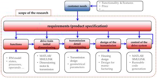
Figure 1.
Scope of the presented research.
The following steps and domain models are integrated in this process: drive train rough estimation via SIMULINK (drive train simulation model—SIMULINK is a software from The MathWorks, Natick, MA, USA), gear-specific model (gear set oriented drive train model), geometry model, control design models, detail model for simulation of the vehicle and of its controller function and code generation from the simulation model. Determining a suitable solution to a given design problem essentially can be understood as an continuous interplay between reasoning about required properties and functions and the particular combination of solution elements which will be provided for this, as well as simulations of their behavior (compare [3,4]). This leads to an iterative process consisting of analyzing and gradually synthesizing the potential solution. It should be noted that some of the solution features or constraints might necessitate a partial or complete redefinition of the problem [5]. Such iterations are not limited to individual design stages, but carry through the entire design process. These iterations have to go hand-in-hand with a continuous update of the models, which represent the respective information [6]. Graph-based design languages offer a promising approach to address the issues of laborious manual transfer and incomplete, inconsistent linking. Such languages generate a digital meta- or system model, storing all relevant information about a design and feed this into any relevant computer-aided engineering (CAE) tool as needed to simulate and test the impact of any design variation on the resulting product performance. As this can be automated in digital compilers to perform systematic design variation for an almost infinite amount of parameters, such graph-based languages are a powerful means to generate viable design alternatives—and thus permit fast comparison and selection—much faster than any design team manually could. This paper investigates the underlying challenges and proposes a digital design process.
The main focus of this paper is on the digital design process. The object of this process is a drive system for a balanced two-wheel scooter. Due to the need to balance the vehicle and simultaneously to follow a given path, the use of two individual actuators on each wheel and an elaborate control system with a continuous tracking of the inclination angle is inevitable. Due to many aspects such as simplicity, the choice of electrical motors as actuators is logical. An initial design step was needed in order to determine whether a gear system is necessary and which transmission ratio would be beneficial for certain configurations. It became apparent that designs which use a transmission are more beneficial for the given set of requirements (including system costs), leading to the general drive system configuration shown in Figure 2.
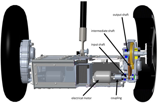
Figure 2.
Scooter drive system—overview.
Visible in the cross-section shown in Figure 2 are one of the two electrical motors, a coupling and the shafts of the transmission system. Together with the inclination sensor and the control system, they represent the key technologies of the balanced two-wheel scooter. The chosen drive system is also similar to drive systems in mobile two-wheel applications (compare [7]). The integration of alternative technical solutions in the digital design process is discussed in the reflections section. The main research goal was the development of a digital design process for this and similar vehicles. This process is realized by applying graph-based languages. The underlying concept of graph-based design languages is described in the next section. Methods and tools for the continuous management of requirements are the contents of Section 3. In Section 4, an approach for functional representation is explained. The concrete dimensioning of the motor and transmission of the balanced two-wheel scooter is discussed in Section 5. Based on the general dimensions and detail, dimensioning of the transmission was possible; this is described in Section 6. One main challenge of balanced two-wheel scooters is the control system—the model-based development is explained in Section 8. In Section 9, the digital design process is reflected and advantages and challenges are discussed. The final section of this paper presents a conclusion and an outlook to further research topics and activities.
2. Graph-Based Design Languages
Graph-based design languages provide a powerful engineering framework through their automated, systematic variation and calculation features, and have the capability to feed into any relevant CAE tool. They map product information into vocabulary and rules typically based on the Unified Modeling Language (UML). These languages permit machine execution and the reuse of design and manufacturing knowledge, through automated model generation, calculation and simulation. They allow the generation of a large number of design alternatives based on parameter variation across multiple simulation tools, in a fast and automated manner [8,9,10,11,12,13,14]. Figure 3 shows some successful applications of graph-based design languages.
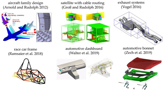
Figure 3.
Successful applications of graph-based design languages.
In graph-based design languages, the geometry can be abstracted to its parts and their abstract geometry. The parts can be organized into the class diagram which represents the vocabulary of the design language. This vocabulary can be used together with rules in order to generate the geometrical model of the product. One important objective of the application of graph based languages is to accelerate innovation. A second central goal is to develop knowledge representations and, through this, to enable a processing of the product lifecycle that allows for more human-independent technological process integration, thereby improving knowledge transfer. The basic concept of a graph-based design language is illustrated in Figure 4.
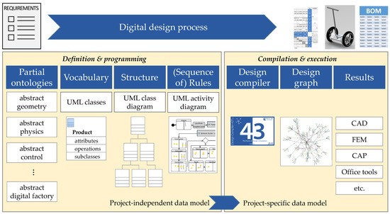
Figure 4.
Concept of a graph-based design language.
Individual components of a graph-based design language are UML classes, which represent the objects of the product (vocabulary). These components can be arranged in ontologies (an ontology is an organized, annotated, related and/or hierarchical arrangement of engineering entities, which may represent aspects of engineering knowledge). These classes are connected in the UML class diagram by different associations and are instantiated via UML model transformations (rules). A sequence of such rules is modelled in an activity diagram. A central element of the digital design process is the Design Compiler 43™ (DC43 for short, see www.iils.de for details). DC43 uses the different sources of information to create the design graph. From this central meta- or system model, further models (for example computer-aided design (CAD) geometry models, simulation models like FEM (finite element method) or multi-body-simulation (MBS) models, descriptions of abstract physics, function representations, a bill of materials, etc.) can be generated in a fully automatic manner. In the balanced scooter project, several generic models could be generated in Figure 5.
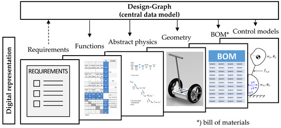
Figure 5.
Design graph with digital models.
The design compiler can process design languages on all abstraction levels to the full detail of the simulation models. This leads to a completely automated process within a unified framework. The design compiler executes the design rules and automatically derives the analysis models of the respective design domains (CAD, CFD (computational fluid dynamics), FEM, etc.). The information content is not limited to geometry, but can also include information concerning physical loads, materials, functions, etc. The work on “DesignCompiler43” is ongoing, but many important functionalities are already available in the current version. The starting points of the digital development process are requirements; their management is the topic of the subsequent section.
3. Requirements Management
Requirements are a decisive factor in system development projects in industry (compare e.g., [15]). Studies [16,17] show that four of ten top risks in projects are strongly connected with requirements and that only 52 percent of the originally intended requirements appear in the final released version of the product. An enormous amount of literature concerns requirements management and requirements engineering; a good overview can be found in [18,19,20]. Additionally, international standards exist: the ISO standard 29148 “Systems and software engineering—Life cycle processes—Requirements engineering” [21], the ISO standard 15288 [22] “Systems and software engineering—Systems life cycle processes” and the quality management norm ISO 9001 [23]. Today, several tools for requirements management are currently available; a comprehensive overview is given in [24]. Additionally, open source products are available, which can provide extensive functionality, such as the Eclipse (Eclipse is an open-source programming tool for developing software of various types which is managed by the Eclipse Foundation, Ottawa, Canada, a non-profit corporation with the mission to manage the Eclipse open source community and its projects)-based tool “ProR”; Figure 6 shows an example of the requirements of the balanced two-wheel scooter modelled in ProR.
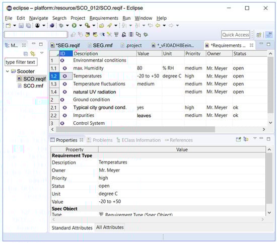
Figure 6.
Requirements management with Eclipse “ProR”—example.
In earlier research, a concept for model-based requirements management was developed [25]. The central objectives of the research were to demonstrate an integration of this model-based requirements management with a development process of gear systems by means of applying graph-based design languages. For the innovative approach, two models were developed—one model for generating various gear system design variants and a second model for requirements management (RM), which includes state of the art RM know-how. The RM-model, as well as the model for product design variants, has been implemented by means of graph-based design languages that are based on UML (Unified Modelling Language). For the explicit digital mapping, the definition of an interface between both models (“requirements” and “geometry synthesis and simulation”) is needed. The model-based requirements management has, in very general terms, three main aspects, which could also be understood as dimensions (Figure 7).
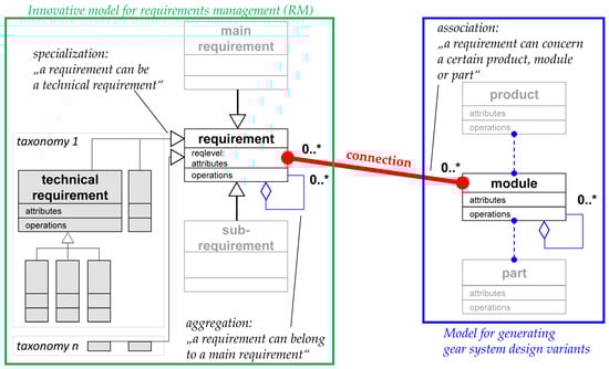
Figure 7.
Product classes linked to requirement classes.
The first dimension consists of the model for generating gear system design variants (right blue frame). The second dimension consists of the model for requirements management (left green frame) and the third dimension consist of the linking of requirements to the product graph. This linking is represented by a red association link. For this, attribute “RelatedToPart” is introduced within the structuring of requirements. This expansion of the framework of graph-based languages allows a concrete assignment from a certain requirement to its related product, module or part. The next section discusses how functional representations can be included in this framework.
4. Functional Representation
The domain of product functions describes the solution concept of a product on an abstract level and supports the description and synthesis of complex, multi-domain products. This section describes possibilities to expand the applicability of graph-based design languages into the domain of product functions. These possibilities allow one to cohesively link integrative function modelling to product structures and intend to close the gap between the early, abstract stages and the systematic, concrete design generation and validation with relevant simulation tools. The approach is based on the integrated function modelling framework (IFM [26]), which is intended to provide development engineers with an integrated, cross-disciplinary approach for modelling system functionality. In this context, a function is defined as an intended or already perceivable behavior of a technical system to fulfil a specific task. The respective function information is presented in associated views; an example for the use case “drive balanced scooter” is given in Figure 8.
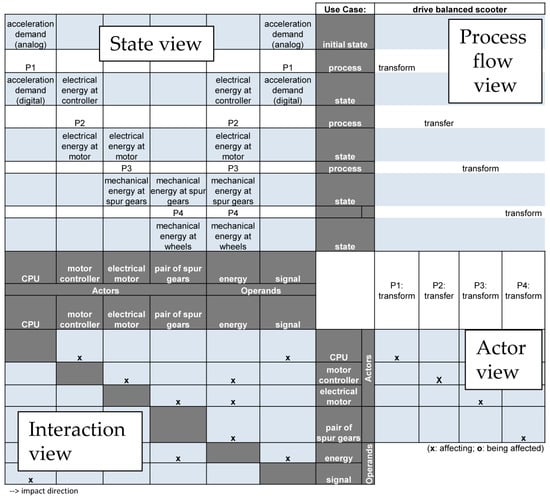
Figure 8.
Associated views in the IFM framework.
The state view (upper left) represents the states of operands, as well as their changes associated with related processes. The process flow view (upper right) qualitatively visualizes the flow of sequential or parallel (interaction or transformation) processes related to a specific use case. The interaction view (lower left) maps the bilateral impacts between actors and operands and represents the structure of the system. The actor view indicates the involvement of one or more actors in the realization of individual processes. For linking this approaches with the concept of graph based design languages, the class diagram of IFM has been re-modelled in UML in order to be able to use it in a design language [27]. The respective class diagram can be seen in Figure 9.
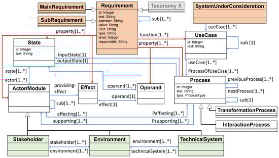
Figure 9.
UML Class Diagram for Function Modelling in DC43.
The entities, as they are represented in the IFM framework, are integrated with the classes and instantiations represented/modelled in DC43. Different from the IFM, for instance, DC43 can be used for requirements engineering as well. Consequently, the class “Requirement” has been added in Figure 5. The requirements are directly linked to use cases. This means, it is possible to identify, which use case fulfils which requirement and which requirements are not covered yet by any use case [25]. Furthermore, some links and interfaces had to be expanded and updated to match the DC43 UML environment. The existing UML model including requirements and functions could be used for the further steps—the dimensioning of motor and transmission as well as the design of the gear system and the control of the drive system.
5. Dimensioning of Motor and Transmission
For the synthesis of the drive system of the balanced two-wheel scooter, a process with steps shown in Figure 10 is implemented. The blue-colored steps are part of an automatic process chain which is implemented in a graph-based design language (GBDL). Each process step is linked to the main requirements of the vehicle or sub requirements derived from them and from the information, and therefore parameters from the previous process.
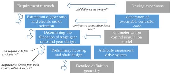
Figure 10.
Process of drive train synthesis with validation.
For the design of the drive train of the self-balanced scooter, the following requirements could be identified out of the (main) vehicle requirements:
- high wheel torque in terms of the controllability of the vehicle (extinction of the pitch angle ),
- accessibility of the desired rated vehicle speed of 20 km/h and
- acceleration capability at rated speed to ensure angle control at each operating point.
To achieve this, a drive system consisting of an electric motor and a gearbox is chosen. This chapter is about the characterization of the main performance features of the motor and the transmission. Because of the focus of the research, a suitable electric motor will be purchased and not designed. Therefore, a database with 49 motors from various manufacturers is available as the basis, containing all relevant motor data, such as armature resistance [Ohm], torque constant [Nm/A], armature inductance [H] etc. To evaluate a motor and transmission combination, a substitution model for the scooter is built. The ratio of the gear system is the parameter with the greatest influence on the dynamics of the vehicle and will be identified. Each motor is combined with different gear ratios via a single-track vehicle model, see Figure 11. The single-track simulation model contains a drive train, which consists of an electric machine (blue) with a gearbox (green) and a vehicle with traction wheel (red). This model includes basic driving resistances due to acceleration and rolling friction. When running the simulation, the vehicle mass is accelerated. The gear ratio of the drive is varied in the range from to in an adjustable step size. In the specific use case, this results in 7840 simulation runs with a step size of . The step response of the system with regard to a voltage jump is determined for each simulation.
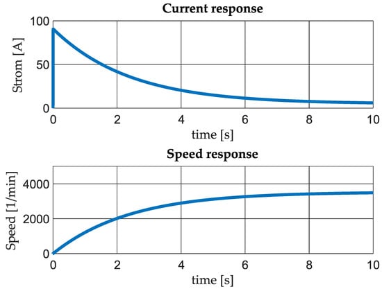
Figure 11.
Step response as early dynamic evaluation approach.
The step response is evaluated with regard to the following criteria, which are assessed as relevant with regard to the requirements mentioned:
- time to rated speed,
- acceleration ability at start moment and
- acceleration at rated speed.
The step responses can be used to compare the various motors with their different gear ratios and to make a decision for a suitable combination. The result is the best performing motor with its appropriate gear ratio. Due to the substitution model, an overall ratio of in combination with a low price BLDC motor “Turnigy Aerodrive SK3” [28] could be determined as an acceptable solution. After the precise design of the transmission geometry in Section 7, it is only then possible to assess the dynamics behavior in Section 8.
6. Detail Dimensioning of the Transmission
The process presented in this chapter generates a preliminary transmission design from the desired overall gear ratio and the drive train performance data. The process is divided into the following sub-steps:
- deriving the geometric requirements of the transmission,
- automatic synthesis of the gear set including parameter variation, as well as decision for one solution and
- generation of a geometry model, design of bearings and shafts, evaluation of the overall design.
For this purpose, the following compound requirements could be generated from previous process and the vehicle as a system:
- packaging restrictions—low center of gravity, therefore motor below the driver standing area; results in a center distance from traction wheel of the vehicle to motor shaft, mm,
- limitation of the installation space due to the frame and the rim of traction wheel is converted into a maximum lateral deflection of the gear set, mm, see Figure 12,
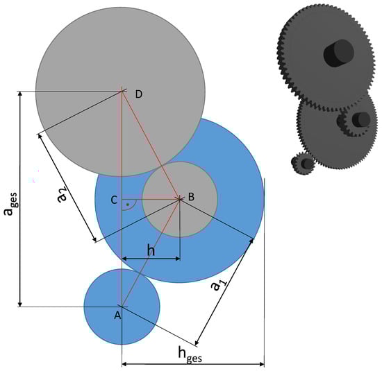 Figure 12. Geometrical parameters at a two-stage gear system.
 - Performance data for motor and overall gear ratio (max input torque Nm, max input speed min−1, overall ratio ).
There are further requirements for the design of the gear set, including parameters such as desired safety values, application factors, etc. For the synthesis of the gear geometry using GAP (Getriebeauslegungsprogramm—German for gear system dimensioning program) [29], a design criterion must also be defined, here, e.g., the requirement for a minimum mass of the gear set is used. Via GAP, the gear geometry is generated in an explicit way according to the requirements and stored in the graph. For this purpose, an interface for commanding GAP and feeding back the data from the gear set to the central data model is implemented. The design of the gear set is repeated for several parameters, a design space is fully factorial scanned. The geometric parameters are shown in Figure 12.
The variable parameters for the exploration of the two-stage gear set scheme are the ratio distribution of the overall ratio to the two stages and the center distances of the two individual stages. When dividing the overall ratio, the ratio of the first stage is varied and the ratio of the second stage results from the interrelation:
The two center distances of the gear stages ( and ) are varied in the range of 40–90 mm for the scooter gear system use case. The size of a bearing system for the shafts limits the minimal distance of the shafts at 40 mm. The upper bound of 90 mm is estimated in terms of the number of variants. In addition, a valid total center distance of 112.5 mm can only be achieved if the following geometrical relationship is given:
The geometrical relation of the deflection h of the two-stage gear set can be formulated as follows with regard to the maximum height of the triangle ABD.
If the radius of the larger wheel of the intermediate shaft is added to the h, the result is , whereby the requirements for every valid design must apply . These mentioned boundary conditions must be fulfilled for all generated variants in order to be eligible. By integrating the gear synthesis into the graph-based design language, the model can be used for subsequent design steps and further evaluations of the drive train. A simple geometry model is created for all generated gear sets, and the shaft-hub connections between the wheels and their shaft is calculated using a simplified approach referred to [30]. In addition, the bearing lifetime is calculated using an approach based on [31]. All the determined properties are saved in the central data model in the form of a graph. Figure 13 visualizes the central data model of a design in a simplified manner.
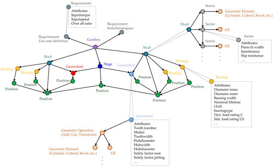
Figure 13.
Design graph as a central data model for the drive train.
The properties of the gear set mass and the power loss are shown for the generated variants in Figure 14. The investigation for the scooter gearbox produces 13,892 valid geometrical variants of the gear set.
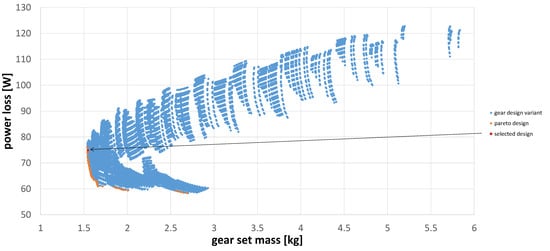
Figure 14.
Design exploration and its evaluation according to power loss and gear set mass.
The left-lower limit of the variant point cloud represents the so-called pareto-front (orange) with regard to the two evaluation parameters (power loss and gear set mass). The selection of one progressed design variant happened from a procurement perspective. The gear geometry needed to be adapted to the on market available gears, as no gear production was possible within the scope of the research, see red point Figure 14. The parameter configuration of the final design is ; and ; mm. This preliminary design with its central data model, including the evaluation it contains, is used to create a manufacturable design, this is presented in Section 7.
7. Design of the Gear System
This section describes the detail design of the gear system with the housing ready to be manufactured. Due to the results of the automatic modelled and dimensioned motor and transmission unit, a detailed CAD model of the electric drivetrain is designed. Of the very many requirements, including manufacturing requirements, only a few requirements are mentioned here:
- mechanical integrity—load cases for driving situations,
- mounting points for motor, rotor position sensor, shaft seals, etc.
- assemblability of the gear system—result in a splitting concept of the housing and
- geometrical requirements of the selected gear set.
Subsequently, the derivation of load cases and the associated evaluation is shown; also, the final design of the balanced two-wheel scooter drivetrain is presented. Due to the target weight of the scooter and a maximum carrying capacity of about 100 kg, and an overall weight of 145 kg as a main vehicle requirement it is possible to elaborate sub requirements for load cases. Besides the installation space model, the critical load cases are very important for the ongoing drivetrain design. One critical load to evaluate the mechanical integrity is the curbstone crossing. The structure of the housing and mountings should withstand such a curb crossing at a driving speed of km h−1. It is assumed that the vehicle passes over a curbstone with a height of mm. According to the following Equation (5) mentioned in [32], the peak vertical acceleration during the curb crossing is calculated by the traction wheel radius r, the height of the curb h and the velocity of the vehicle v:
The calculation leads to 13 g peak acceleration during the curb crossing. After considering the damping effects of the tire, the peak acceleration is reduced to approximately 10 g. Including the mass of the scooter and the estimated peak acceleration, a maximum vertical force has been calculated as the critical force caused by driving the scooter. The second critical load is referenced to the weight and torque of the electric motor. In order to be able to install and remove the drive system as a complete module, the motor is supposed to be connected to the transmission housing. According to the motor specification, the motor has an overall weight of kg and a peak torque of Nm [28]. This means that the design of the drive unit has to support the torque and weight. The weight of the motor, similar to the total weight of the scooter, has to be held up with a permissible deformation for a curb crossing of 10 g. As shown in Figure 1, the previously mentioned requirements are taken into the design and verified and optimized by simulations.
According to the vehicle requirements, an installation space model for the drive unit is generated. The model shown in Figure 15 presents three different views, including the possible installation space for the drive unit (yellow marked geometry), which absorbs the previously specified interfaces to the gear set, such as the connection to the wheel hub and the attachment points of the frame. According to the requirements, it should be possible to install the drive unit on both sides of the balanced two-wheel scooter. For this reason, special care was taken to ensure that the attachment points and the motor, as well as the output shaft, are arranged symmetrically to each other. Based on the automatically generated gear set and the defined interfaces, a first model of the gearbox housing is created, limited by the installation space. The detailed model is created in the design software Creo Parametric 5.0. A finite element method (FEM) simulation is generated in Creo Simulate to verify the required load cases (Creo Parametric 5.0 as well as Creo Simulate are software tools of the PTC Inc. from Boston, MA, USA). After the boundary conditions are transferred into the model, the mesh size is investigated by a convergence and divergence study. For the studies shown in Figure 9, the elemental stresses are investigated according to von Mises. The divergence study is used to check the mesh size in the border areas and the convergence study of the mesh fineness in the unbounded area [33]. For each of the studies, one element is tested with different mesh sizes (visible in Figure 16).
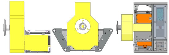
Figure 15.
Space Model for the drivetrain view form front, side and above.
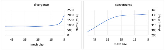
Figure 16.
Convergence and divergence behavior for different mesh sizes.
The divergence study shows that no valid analysis of the stresses in the border areas can be achieved with a grid fineness of less than 10. The convergence study shows that no significant change in the stresses in the unbounded area can be detected from a mesh size of less than 25. Accordingly, a mesh size of 10 is used for the more detailed analysis of the load cases. A further advantage of this mesh size is the computing time, which is kept to a minimum. This is decisive for the optimization process, in order to simulate a high value of different geometries by achieving valid results. The above-mentioned optimization of the component geometries mainly concentrated on the component displacement, as the element stresses in all components are consistently lower than the critical material parameters allow. The comparison shown in Figure 17 represents the deflection of the drive unit in the Z-direction viewed from the side.
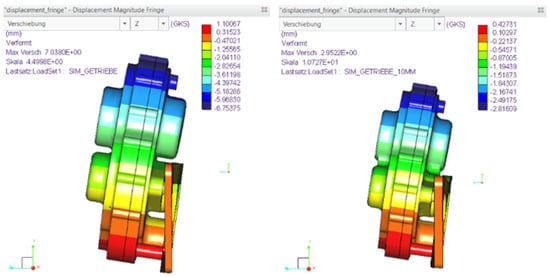
Figure 17.
Displacement with the first design (left) and the optimized geometry (right).
On the left-hand side, the simulation result of the first created geometry is shown. On the right-hand side, the finally selected and optimized geometry is shown. During the optimization process, the component displacement could be reduced by about 60%. For stiffening the individual parts, for example, ribs are inserted between the individual bearing seats of the transmission housings. To increase the stiffness at equal weight, it is necessary to thicken the mounting plate to mm and remove material according to the load paths. To further reduce the overall weight and costs, a geometry for additive manufacturing with polylactic acid (PLA) is designed. Therefore, a topology optimization is implemented for the motor connector. For the topology optimization and the following FEM simulation the structure is simulated considering the maximum motor torque and the impact of the motor weight during the curb crossing. Figure 18 shows the results of the FEM simulation.
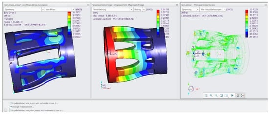
Figure 18.
FEM simulation of the topology optimized motor connector—load case curb crossing.
The motor is coupled to the input shaft of the transmission with a flexible coupling. Therefore, two criteria can be defined to investigate the component. On the one hand, the critical material parameters of PLA are not allowed to be exceeded and on the other hand the displacement of the connection may not exceed the maximum possible flexible coupling deflection (max. angle of ) [34]. Otherwise, bending loads could damage the coupling and increase bearing loads. As shown by the simulation results, neither of the two criteria are reached or even exceeded by the critical loads.
Another crucial aspect was the supply of lubricant in the gear system. The requirements for the oil system included sealing, as well as ensuring a sufficient supply of lubricant to the gears and bearings. The first one is realized by using an O-ring seal cord and proper radial shaft seals. The second is checked by a fluid simulation. The purpose of the simulation is to determine the amount of oil required for reliable operation of the drive train and how well the individual bearings and gears are supplied with lubricant. Figure 19 shows a screenshot from the simulation set up in the software PreonLab. PreonLab is a fluid simulation tool developed by the FIFTY2 Technology GmbH from Freiburg, Germany. Based on the results of the simulation, a filling level of 50 mL is determined to be appropriate for the safe operation of the transmission.
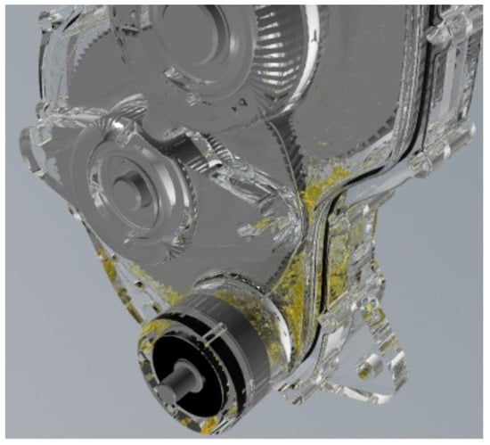
Figure 19.
Analysis of the splash lubrication system by using the software PreonLab.
The resulting drive system with its components can be seen in Figure 20.
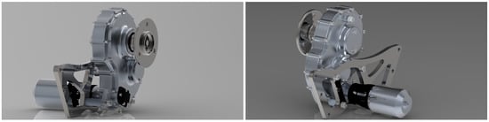
Figure 20.
Drivetrain module of the scooter.
After the entire drivetrain is designed, verified and optimized according to the requirements, a detailed centre-of-gravity (COG) model is derived. This model includes the vehicle COG and the rotational moment of inertia of the drive train. These data are transferred back to the central model to be used as parameters for the automated controller configuration.
8. Control of the Drive System
In order to guarantee the functionality of the above derived scooter design, the dynamic properties stated in the product requirements must be checked. Typical requirements for the balanced two-wheeled scooter are, on the one hand, stability of the attitude dynamics and, on the other hand, a firmly defined transfer behavior of disturbances introduced by the human driver on the translational velocity of the scooter. These properties can be concretized in the design of the control system in the form of overshoot width , overshoot time and settling time of the system for appropriately selected step responses, as show in Figure 21. The settling time refers to the case in which the setpoint remains within a specified value range .
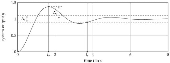
Figure 21.
Schematic of a step response and its characteristics.
In case of the proposed scooter design, four different cases of simulation scenarios are proposed to define the dynamic behavior of the scooter. The first and most crucial specification is a demand on the stability of the attitude dynamic, thus stabilizing an unstable pole describing a pitch movement of the platform body around its rotation axis. The second specification specifies the suppression of input disturbances created by the human driver based on a shift of his center of gravity. The last two specifications make demands on the tracking behavior of the control system. They specify the dynamic properties of the tracking of a commanded velocity and the tracking of the yaw rate .
A detailed listing of the specifications can be seen in Table 1.

Table 1.
Specification of the dynamic properties of the scooter.
In order to check these requirements, the closed loop behavior of the scooter is simulated. This leads to a knowledge of the control variables, and thus the drive system defined above can be validated with respect to the required demands. Firstly, the dynamic model used to simulate the balanced two-wheeled scooter is introduced. A schematic of the plant model is shown in Figure 22.
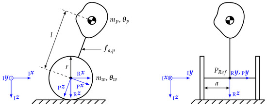
Figure 22.
Schematic of the segway model with a heading .
As can be seen in Figure 22, a minimal set of independent variables can be given by
consisting of the position coordinates x and y and the yaw angle and pitch angle . The dynamic system consists of three bodies, the main platform with the passenger and the two wheels. The two wheels are mounted on an axle with a length and the center of mass of the wheel bodies lie in their respective rotation axis, thus the inertia tensor of each wheel is invariant to rotation around their respective rotation axis. The length of the lever of the center of gravity of the platform body with respect to its rotational degree of freedom is described by the parameter l. A simplification made in the modeling is that the wheels can only move in the body fixed x direction, thus narrowing the degrees of freedom in the derivatives of the independent variables , as depicted in Equation (7):
Thus, for this problem, the kinematic description of the wheel movement of the reference point in the center of the wheel axle based on [35] can be given in the form
with the help of the translational velocity v and the heading of the scooter. Based on the translational velocity of the reference point , depicted in Equation (8), the translational velocity of the n-th wheel body can be expressed in the inertial frame:
The vector used in Equation (9) describes the position of the wheel with respect to the reference point and only depends on the axle length a, if described in the R-frame. The transformation matrix describes the transformation of the inertial frame to the R-frame and can be fully defined by a elementary rotation with the angle around the axis. In order to describe the change in the orientation of the R-frame with respect to the body fixed frame, the angular rate is introduced as show in Equation (10).
Similar to the translational velocity of the wheels, the translational velocity of the platform can be formulated with respect to the reference point , as shown in Equation (11).
The vector describes the position of the center of mass of the platform body, which only depends on the arm length l and is a time invariant quantity, if described in the P-frame. The transformation matrix describes the orientation of the inertial frame with respect to the P-frame and is defined by two sequential elementary rotations. The first rotation describes a rotation with the angle around the axis and the second rotation describes a rotation with the angle around the axis of the new coordinate system. In order to fully define the translational velocity of the platform depicted in Equation (11), the rotational velocity is needed
which describes the change of orientation of the platform system with respect to the inertial frame. To fully describe the motion of the individual bodies of the scooter, it is necessary to link the translational velocities v and the yaw rate with the rotational velocity of the wheel bodies. Based on the fact that the scooter does not experience any slip, this relationship can be expressed in the following equations:
Based on the above introduced Equations, (13) and (14), the rotational velocity of the wheel can be expressed as illustrated in Equation (15).
In order to describe the dynamic model based on d’Alemberts principle, the whole momentum of the system needs to be in a state of equilibrium, thus leading to the following relationship:
In order to describe the momentum of the platform, the mass of the platform and the translational acceleration in the inertial frame are needed, which can be easily calculated based on Equation (11). Similarly, the momentum of the n-th wheel can be expressed based on its mass and the time derivative of its translational velocity in the inertial frame depicted in Equation (9). To describe the rotational momentum of the platform or of the n-th wheel body in its respective body fixed frame, the inertial tensor of the platform and of the wheel and their angular acceleration in the body fixed frame are needed. These can be evaluated based on the description of their angular velocities described in the Equations (12) and (15). The Jacobian matrices, , , and , describe, with respect to the choosen independen variables, the directions in which the systems body is allowed to move. They can be expressed by the partial derivatives of the translational and rotational velocities of each body with respect to the vector . To describe the external influences on the system, the external forces and moments acting on the system needs to be defined as follows:
The moments produced by the two motors are taken into account by the quantities . The dynamic model depicted in Equation (16) can be reformulated in the mass matrix form:
The external torques acting on the platform system and on the wheels mainly consist of the torques produced by the n-th motor of the scooter. Taking the dynamic properties of the motor into account [36], the full dynamic model reads
with the state vector
Parameters of the motor model are the electrical resistance R, the inductivity L and the magnetic flux of the motor. In order to automatically generate the simulation model, the inertia properties and the positions of the center of masses of the different bodies with respect to the reference point need to be extracted. This can be easily done with the help of a random CAD-Kernel. A possibility to model a multibody system in a design language is shown in Figure 23.
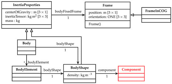
Figure 23.
Class diagram of a multibody library.
The central class of this library is the “Body” class, which inherits a set of inertia properties needed for a multibody simulation and each body can be disassembled into an infinite set of elements to be able to represent different assemblies, which can be combined to one body in the sense of a multibody simulation. To take care of the coordinate sytems in which the different quantities are expressed, the “Frame” class is introduced. It describes the rotation and translation to the inertial coordinate frame, thus all quantities can be expressed in a frame which is chosen with regard to the topology of the multibody model. The interface class to the geometric representation is the “Component” class, a class originating from a DC43 library which represents instances with a geometric shape. In this development process, the automated design process is inturrepted in the detailed design of the gear system, which is depicted in Section 7. If this design process could be automated too, the multibody simulation could be triggered automatically based on the model proposed in the class diagram shown in Figure 23.
The last step of the design process would be the closed loop simulation of the plant model. For this purpose, Matlab/Simulink was used. The controller design chosen for the scooter design is depicted in Figure 24.
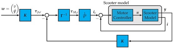
Figure 24.
Schematic of the closed loop model.
The controller is based on a simple output feedback controller for the pitch and velocity dynamic and a separated state feedback controller for the yaw dynamics. This controller design and its decoupled nature between the pitch and the yaw dynamic is extensively discussed in [37,38,39,40,41]. The output vector consists of the output for the pitch and velocity controller and the output for the yaw rate controller. Similar to this, the gain matrix is a block diagonal matrix consisting of the vector of the pitch and velocity controller and the vector of the yaw rate controller. In order to map the torques calculated in the two decoupled controllers on the actual actuators, a simple allocation scheme
is used, which is uniquely defined for all combinations. To define the gains of the control system in order to fit the specified requirements, a linear design model based on a subset of the nonlinear model depicted in Equation (22) is used. It reads
with the state vector and the output vector
In this design model, the dynamic of the current controller of the motor is taken into account too, because in order too stabilize the unstable pole of the pitch dynamic, a very fast response is needed and thus unwanted coupling effects with the motor dynamic should be avoided. The control law for the current controller reads
which creates a current output . It can be seen that the model is extended by the state , which describes the integrated current error of the controller. The output feedback control law for the pitch and velocity dynamic reads
which generates a commanded value based on the state of the pitch and velocity dynamic. In order to achieve steady state accuracy, the integrated error of the velocity command is taken into account by the state . The control laws shown in Equations (29) and (30) combined with the simplified linear design model of Equation (25) can be used for pole placement [42] to achieve the specified dynamic properties. The poles are placed in order to satisfy the condition
thus specifying the eigenfrequency and damping of the closed loop model. If the chosen controller does not satisfy the required dynamic properties in the nonlinear simulation, the eigenfrequency and damping of the system can be adapted automatically. Similar to velocity and pitch dynamic, the yaw rate controller can be designed. In this case, the motor dynamic is neglected. Thus, a simple linear model for the design of the controller can be expressed by
with the state vector
The state feedback control law reads
and generates a torque command based on the state and the integrated error of the yaw rate. The pole placement [42] can be achieved by satisfying the following condition
with the help of the eigenfrequency and the damping of the yaw rate dynamic. Similar to the pitch and velocity dynamic, the controller can be tuned to satisfy the specified dynamic properties, by changing the damping and the eigenfrequency in the design model if the nonlinear validation model does not show the desired effects. In Figure 25, the critical case for the motor design is shown, which is depicted by an error in the pitch angle for the here chosen dynamic properties shown in Table 1.
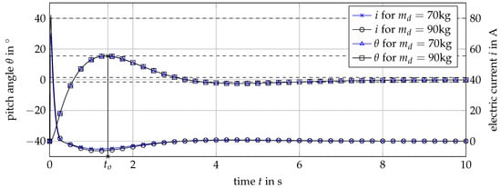
Figure 25.
Simulation data of the stability specification.
An initial estimate for the maximum motor moment or current input was done in Section 5 in order to design the transmission. It can be seen that the trajectories of the pitch angle satisfy the conditions of the max overshoot, overshoot time and settling time for the case of a passenger of kg and kg, but in the second case, the maximum motor current A is violated. For the second case, a redesign of the scooter is necessary; for the first case, a valid scooter design is found, which satisfies all requirements. With the second case, a redesign could be done by using the maximal needed current of the closed loop model as an input in the transmission design.
9. Reflection of the Digital Design Process
The described control system design process is an integral part of the digital design process of the balanced two-wheel scooter, which was realized by means of an integrated engineering framework based on graph-based design languages. All stages are fed with updated input information from a model based requirements management. The processes, operands and states are identified and connected in an integrated function model and actors are connected to the modular product structure under development. Crucial for the developed scooter is the dimensioning of the motor and transmission of the drive system. For the determination of the main performance features of the motor and transmission, an automated synthesis process with integrated validation was presented. The synthesis led to a choice of motor and transmission ratio—this was subsequently the input information for the detail dimensioning of the transmission. This detail dimensioning consists of an automatic synthesis of the gear set using parameter variation and pareto-front-based selection. The concrete design of the gear set included detailed finite element and lubrication analyses. For all kinds of balanced vehicles, the control system will determine the general usability and the driving comfort and safety. A detailed close loop behavior simulation was carried out, based on a controller design with a simple output feedback controller for the pitch and velocity dynamics and a separate state feedback controller for the yaw dynamics.
The central advantages of the presented digital design process in comparison to conventional design process is the possibility for machine execution, i.e., all steps can be carried out in an automatic manner. This allows the synthesis and analysis of a large number of possible solutions and increases the probability of generating and choosing an optimum solution. Additionally, compliance with all product design requirements can only be verified after the design is complete. This applies in particular to the evaluation of the dynamic properties of the closed-loop and the realizability of the control commands. Based on the fully automated design process presented in this paper, a suitable product design can be found by manipulating the input data without additional development work. Another important advantage is that through a large part of the design process a central model can be used in the engineering framework. This reduces the risk of inconsistencies. In the opinion of the involved design engineers, the resulting design process is more robust in case of design changes.
The main challenge in the application of this engineering framework is the necessity of a paradigm shift; the design engineers are, during a large share of the process, not designing a single product, but programming a product variety. In the early stages, a larger investment in terms of working hours and critical thinking is necessary, but the involved engineers tend to believe that the advantages merit this investment.
One common issue in the application of automated design processes is the question of whether innovative solution concepts are possible within this process. One may ask the critical question, if this kind of process limits creativity and will exclude solution possibilities, which are different from an initial concept. This risk is reduced by the possibility to integrate alternative configurations in this engineering framework, which goes beyond digital building blocks, as they are present in conventional design automation systems. The engineering framework allows mutual interdependent components, as well as a large solution variety on functional and physical levels. For the balanced two-wheel scooter example, solutions with completely different transmission systems could still be part of a consistent product family.
10. Conclusions and Recommendations for Further Research
This paper demonstrated several stages of the digital design process of a balanced two-wheel scooter. An integrated engineering framework based on graph-based design languages serves as back-bone for this process. The result of the digital development process is the scooter shown in Figure 26.
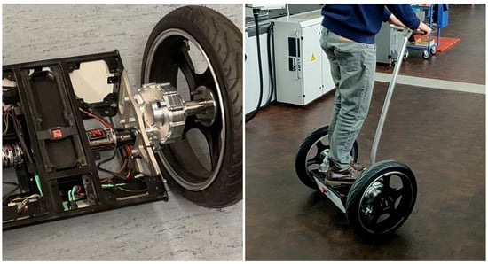
Figure 26.
Build balanced two-wheel scooter
The main advantages of the presented process are the linking of synthesis and analysis steps and the high degree of interconnected, model-based processes on different levels of abstraction and concerning different domains. The engineering framework based on graph-based design languages avoids double inputs, independent generic models and inconsistencies. Conventional tools are mostly only used to evaluate manually defined designs; very few can also be used to generate the models (synthesis). The process shown in this paper still has some gaps in automation, but represents a closed requirements-driven development chain. The gaps in the automation capability are particularly due to the sheer number of requirements—especially in the area of the geometry of the housing. Still, a primarily digital requirement driven design process and an enrichment of requirements along the design process could be demonstrated. Future work is aiming at a further increase of the automation level and the application for even more complex systems. Further possibilities for presenting abstract physics will be included in the engineering framework, and simulation possibilities, as well as synthesis possibilities such as topology, will be expanded. Additionally, the scientific foundation for a stronger integration with model-based system engineering systems will be addressed.
Author Contributions
Conceptualization, K.H., M.T., R.S., W.F. and S.R.; methodology, R.S.; design and dimensioning, S.S.; simulation, K.H. and M.F.; control design, M.F.; analysis and evaluation, K.H., S.S. and M.F.; writing—original draft preparation, K.H., S.S., M.F. and R.S.; writing—review and editing, M.T., W.F. and S.R. All authors have read and agreed to the published version of the manuscript.
Funding
This research was funded in the scope of the Digital Product Life Cycle (ZaFH) project (information under: https://dip.rwu.de/), which is supported by a grant from the European Regional Development Fund and the Ministry of Science, Research, and the Arts of Baden-Württemberg, Germany (information under: https://efre-bw.de/).
Institutional Review Board Statement
Not applicable.
Informed Consent Statement
Not applicable.
Data Availability Statement
The data presented in this study are available on request from the corresponding author.
Acknowledgments
The authors wish to thank the administrative and technical staff of the Ravensburg-Weingarten University (RWU), for the continuous support and all involved students for their immense contribution.
Conflicts of Interest
The authors declare no conflict of interest.
References
- Gumpert, K.; Wiese, J. Analyse des Potenzials der Elektromobilität im Hinblick auf das logistische Problem der letzten Meile. Mobil. Glob. World 2017, 16, 55. [Google Scholar]
- Burkhart, J.; Breckle, T.; Ramsaier, M.; Till, M. A digital modelling approach for design configuration and manufacturing exemplified by a self-balancing scooter. Procedia CIRP 2020, 91, 214–219. [Google Scholar] [CrossRef]
- Gero, J.S.; Kannengiesser, U. The function-behaviour-structure ontology of design. In An Anthology of Theories and Models of Design; Springer: Berlin/Heidelberg, Germany, 2014; pp. 263–283. [Google Scholar]
- Chakrabarti, A.; Bligh, T.P. A scheme for functional reasoning in conceptual design. Des. Stud. 2001, 22, 493–517. [Google Scholar] [CrossRef]
- Braha, D.; Reich, Y. Topological structures for modeling engineering design processes. Res. Eng. Des. 2003, 14, 185–199. [Google Scholar] [CrossRef]
- Eckert, C.; Albers, A.; Bursac, N.; Chen, H.X.; Clarkson, J.; Gericke, K.; Gladysz, B.; Maier, J.; Rachenkova, G.; Shapiro, D.; et al. Integrated product and process models: Towards an integrated framework and review. In Proceedings of the ICED 2015, Seoul, Korea, 13–16 April 2015. [Google Scholar]
- Rubio, F.; Valero, F.; Llopis-Albert, C. A review of mobile robots: Concepts, methods, theoretical framework, and applications. Int. J. Adv. Robot. Syst. 2019, 16, 1729881419839596. [Google Scholar] [CrossRef]
- Rudolph, S. Übertragung von Ähnlichkeitsbegriffen; Universität Stuttgart: Habilitationsschrift, Germany, 2002. [Google Scholar]
- Arnold, P.; Rudolph, S. Bridging the gap between product design and product manufacturing by means of graph-based design languages. In Proceedings of the TMCE 2012 Symposium, Karlsruhe, Germany, 7–11 May 2012. [Google Scholar]
- Gross, J.; Rudolph, S. Geometry and simulation modeling in design languages. Aerosp. Sci. Technol. 2016, 54, 183–191. [Google Scholar] [CrossRef]
- Vogel, S. Über Ordnungsmechanismen im Wissensbasierten Entwurf von SCR-Systemen. Doctoral Thesis, Universität Stuttgart, Stuttgart, Germany, 2016. [Google Scholar]
- Ramsaier, M.; Stetter, R.; Till, M.; Rudolph, S. Modelling and Simulation of a Race-Car Frame Using Graph-Based Design Languages. In Proceedings of the International Conference on Engineering Optimization, Lisboa, Portugal, 17–19 September 2018; pp. 789–800. [Google Scholar]
- Walter, B.; Kaiser, D.; Rudolph, S. From Manual to Machine-executable Model-based Systems Engineering via Graph-based Design Languages. In Proceedings of the MODELSWARD, Prague, Czech Republic, 20–22 February 2019; pp. 201–208. [Google Scholar]
- Zech, A.; Stetter, R.; Holder, K.; Rudolph, S.; Till, M. Novel approach for a holistic and completely digital represented product development process by using graph-based design languages. Procedia Cirp. 2019, 79, 568–573. [Google Scholar] [CrossRef]
- Bernard, R.; Irlinger, R. About watches and cars: Winning R&D strategies in two branches. In Proceedings of the International Symposium “Engineering Design The Art of Building Networks”, Munich, Germany, 4–5 April 2016. [Google Scholar]
- Hruschka, P. Business Analysis und Requirements Engineering: Produkte und Prozesse Nachhaltig Verbessern; Carl Hanser Verlag GmbH Co KG: München, Germany, 2019. [Google Scholar]
- Ebert, C.; Jastram, M. ReqIF: Seamless requirements interchange format between business partners. IEEE Softw. 2012, 29, 82–87. [Google Scholar] [CrossRef]
- Darlington, M.; Culley, S. A model of factors influencing the design requirement. Des. Stud. 2004, 25, 329–350. [Google Scholar] [CrossRef]
- Jiao, J.; Chen, C.H. Customer requirement management in product development: A review of research issues. Concurr. Eng. 2006, 14, 173–185. [Google Scholar] [CrossRef]
- Zhang, Z.; Li, X.; Liu, Z.L. A Closed-loop Based Framework for Design Requirement Management. In Proceedings of the ISPE CE, Beijing, China, 8–11 September 2014; pp. 444–453. [Google Scholar]
- ISO. Systems and Software Engineering—Life Cycle Processes—Requirements Engineering; International Organization for Standardization: Geneva, Switzerland, 2011. [Google Scholar]
- ISO. Systems and Software Engineering—System Life Cycle Processes; Standard ISO/IEC 15288; International Organization for Standardization: Geneva, Switzerland, 2008. [Google Scholar]
- ISO. Quality Management Systems—Requirements; Standard ISO 9001; International Organization for Standardization: Geneva, Switzerland, 2015. [Google Scholar]
- De Gea, J.M.C.; Nicolás, J.; Alemán, J.L.F.; Toval, A.; Ebert, C.; Vizcaíno, A. Requirements engineering tools: Capabilities, survey and assessment. Inf. Softw. Technol. 2012, 54, 1142–1157. [Google Scholar] [CrossRef]
- Holder, K.; Zech, A.; Ramsaier, M.; Stetter, R.; Niedermeier, H.P.; Rudolph, S.; Till, M. Model-based requirements management in gear systems design based on graph-based design languages. Appl. Sci. 2017, 7, 1112. [Google Scholar] [CrossRef]
- Eisenbart, B.; Gericke, K.; Blessing, L.T.; McAloone, T.C. A DSM-based framework for integrated function modelling: Concept, application and evaluation. Res. Eng. Des. 2017, 28, 25–51. [Google Scholar] [CrossRef]
- Ramsaier, M.; Holder, K.; Zech, A.; Stetter, R.; Rudolph, S.; Till, M. Digital representation of product functions in multicopter design. In Proceedings of the DS 87-1 21st International Conference on Engineering Design (ICED 17) Volume 1: Resource Sensitive Design, Design Research Applications and Case Studies, Vancouver, BC, Canada, 21–25 August 2017; pp. 369–378. [Google Scholar]
- Hobbyking. Turnigy Aerodrive SK3-6374-168kv Brushless Outrunner Motor. Available online: https://hobbyking.com/de_de/turnigy-aerodrive-sk3-6374-192kv-brushless-outrunner-motor.html (accessed on 7 December 2020).
- Parlow, J.C. FVA-Nr. 421 IV Erweiterung Getriebeauslegungsprogramm: Benutzeranleitung Getriebeauslegungsprogramm; Forschungsvereinigung Antriebstechnik e.V.: Frankfurt, Germany, 2016. [Google Scholar]
- Deutsches Institut für Normung. Pressverbände—Teil 1: Berechnungsgrundlagen und Gestaltungsregeln für zylindrische Pressverbände; Standard DIN 7190; Deutsches Institut für Normung: Berlin, Germany, 2017. [Google Scholar]
- ISO. Wälzlager—Dynamische Tragzahlen und nominelle Lebensdauer; Standard DIN ISO 281; International Organization for Standardization: Geneva, Switzerland, 2010. [Google Scholar]
- Schimmelpfennig, K.H.; Uphoff, T. Unfallrekonstruktion: Näherungsgleichung für die Berechnung von Fahrwerksbelastung durch Schlaglöcher. VRR Verkehrsrechtsreport 2011, 5, 174–178. [Google Scholar]
- Gebhardt, C. Praxisbuch FEM mit ANSYS Workbench: Einführung in die Lineare und Nichtlineare Mechanik; 2. Überarbeitete Auflage Editon; Carl Hanser: München, Germany, 2014. [Google Scholar]
- MÄDLER GmbH. Artikel 60272600—Ausgleichskupplung KA aus Aluminium max. Drehmoment 4.0 Nm Gesamtlänge 31.75 mm Aussendurchmesser 25.40 mm Beidseitig Bohrung 8 mm. Available online: https://www.maedler.de/product/1643/1622/1945/ausgleichskupplungen-ka-kurz-aluminium?result=60272600 (accessed on 18 December 2020).
- Muir, P.F.; Neuman, C.P. Kinematic modeling of wheeled mobile robots. J. Robot. Syst. 1987, 4, 281–340. [Google Scholar] [CrossRef]
- Isermann, R. Mechatronische Systeme: Grundlagen; Springer: Berlin/Heidelberg, Germany, 2007. [Google Scholar]
- Grasser, F.; D’arrigo, A.; Colombi, S.; Ruffer, A.; Mobile, J.A. Inverted pendulum. IEEE Trans. Ind. Electron. 2002, 49, 107–114. [Google Scholar] [CrossRef]
- Jian-hai, H.; Shu-shang, Z.; Ji-shun, L.; Hang, L. Research on developed parallel two-wheeled robot and its control system. In Proceedings of the 2008 IEEE International Conference on Automation and Logistics, Qingdao, China, 1–3 September 2008; pp. 2471–2475. [Google Scholar]
- Nawawi, S.W.; Ahmad, M.N.; Osman, J.H.S. Development of a two-wheeled inverted pendulum mobile robot. In Proceedings of the 2007 5th Student Conference on Research and Development, Selangor, Malaysia, 11–12 December 2007; pp. 1–5. [Google Scholar]
- Feng, T.; Liu, T.; Wang, X.; Xu, Z.; Zhang, M.; Han, S.C. Modeling and implementation of two-wheel self-balancing robot equipped with supporting arms. In Proceedings of the 2011 6th IEEE Conference on Industrial Electronics and Applications, Beijing, China, 21–23 June 2011; pp. 713–718. [Google Scholar]
- Li, J.; Gao, X.; Huang, Q.; Matsumoto, O. Controller design of a two-wheeled inverted pendulum mobile robot. In Proceedings of the 2008 IEEE International Conference on Mechatronics and Automation, Takamatsu, Japan, 5–8 August 2008; pp. 7–12. [Google Scholar]
- Friedland, B. Control System Design: An Introduction to State-Space Methods; Courier Corporation: North Chelmsford, MA, USA, 2012. [Google Scholar]
Publisher’s Note: MDPI stays neutral with regard to jurisdictional claims in published maps and institutional affiliations. |
© 2021 by the authors. Licensee MDPI, Basel, Switzerland. This article is an open access article distributed under the terms and conditions of the Creative Commons Attribution (CC BY) license (http://creativecommons.org/licenses/by/4.0/).