1. Introduction
Among all main sources of acoustic noise, such as mechanical and aerodynamic, the magnetic source can be very critical in many applications (transport systems, aerospace, electric vehicle (EV) motors, etc.), particularly in high-torque motors, where a large number of poles and a thinner stator yoke always result in a medium mechanical stiffness. This induces magnetic vibration due to magnetic forces which consist of Maxwell and magnetostrictive forces. Fractional-slot concentrated windings (FSCW) are very popular because of many remarkable enhancements during recent years in terms of manufacturability and modularity [
1], increased flux weakening performance [
2], fault tolerance features [
3], and short-end windings [
4,
5]. However, the acoustic noise needs special attention because of the small number of slots per pole per phase q, which causes large magnetomotive force (MMF) distortion due to low-order harmonics in the spatial distribution of the radial forces in comparison to other traditional permanent magnet (PM) machines [
6,
7,
8].
The first attempt to reduce magnetic vibrations and acoustic noise produced in the electrical machines via Maxwell forces has been modeled in Reference [
9,
10].
In recent research work, there are several studies to present the impact of various machine design considerations on magnetic noises with considering variable-speed and natural frequencies conditions as follows.
J. Le Besnerais et al. studied a multi-objective optimization on a fast analytical model of a variable-speed induction machine which calculates both motor performances and sound power level of electromagnetic origin. The model has been coupled to a Non-dominating Sorting Genetic Algorithm (NSGA-II) in order to perform global constrained optimizations with respect to several objectives (e.g., noise level, efficiency, and material cost) [
11]. In another work [
12], the authors present a fast simulation tool for the variable-speed magnetic noise emitted by induction machines, based on fully analytical models. On the basis of these models, they derive and experimentally validate an analytical expression for magnetic vibrations due to slotting reluctance harmonics, confirming the prime importance of slot combination in magnetic noise radiation. Finally, a database that efficiently replaces the old empirical rules for slot combination numbers and helps in designing quiet induction motors has been proposed which can be built for other power ranges. In Reference [
13], an analytical model is investigated that is developed for surface mounted permanent magnet machines with skewed slots via the subdomain technique and the multislice method. In another study [
14], the authors study a step skewed rotor which is applied to the design to reduce electro-magnetic exciting force so that both reduction of vibration and noise and cost-effectiveness of development can be achieved for interior permanent magnet synchronous machines (IPMSMs). Furthermore, the influence of vibration-based forces and noises due to pulse width modulation (PWM) supply in induction machines have been studied in Reference [
15,
16].
1.1. Research Gap and Original Contributions
The vast majority of recent works focused on noise and vibration analyses in electric machines caused by mechanical and aerodynamic sources, such as variability in design, texturing the blades, material features, manufacturing, bearings (sleeve, fluid, and balls), fan selection (radial or axial), etc. The electromagnetic source of noise and vibration (known as e-NVH) has been mainly studied based on empirical principles, like relative permeance (which fails to provide accurate predictions, while a variable-speed-range analysis is needed in traction electric motors, reported in Reference [
17,
18,
19]), and some studies have attempted to use semi-analytical and numerical approaches, such as semi-finite element analysis (FEA) for e-NVH computations. Among them, only a few have reduced the noise and vibration of the electric motor using skewing technique for the electric vehicle applications.
Highly motivated by the research gap, the researchers have proposed a semi-analytical-based approach to compute the e-NVH of the motor under a variable speed range analysis condition with consideration of natural frequencies, and herein, the skewing technique along with various slice numbers on both stator and rotor parts significantly reduced the e-NVH of the in-wheel electric motor for the light-duty electric passenger vehicle. Natural frequency mapping of the motor used in EV application allow the engineers to evaluate the motor’s performance under different driving conditions, such as accelerating and braking. Additionally, the achievements are validated by experimental measurements using the manufactured in-wheel motor. Thereby, the numerical and experimental investigation of the in-wheel PMSM under a variable-speed-range analysis is done for the first time.
This paper investigates the impact of a skewing technique to minimize the vibration level power and audible magnetic noise on a wheel hub-mounted permanent magnet synchronous motor (WHM-PMSM) using a multi-slice subdomain model (MS-SDM) with use of non-overlapping FSCW for a variable-speed-range analysis. With respect to the importance of MMF distortion of the FSCW used, the results of both initial and optimized WHM-PMSM are presented. The skewing angle for a wide-range of skew rate has been expressed by stator slot pitch between 0.8–1.2. We investigate whether or not the skewing slice number is significant to the vibro-acoustic objectives in the studied WHM-PMSM. Although many empirical rules have been established for correctly carrying out the skewing of stator and rotor, as to limit the maximum audible magnetic noise level radiated from the WHM-PMSM, none of these empirical rules have considered the stator’s natural frequencies or variable-speed-analysis. The literature contains papers which have been recently published using empirical-based approaches to choose skewing angle [
20,
21,
22,
23,
24,
25] and numerical-based studies to minimize vibration and noise [
21,
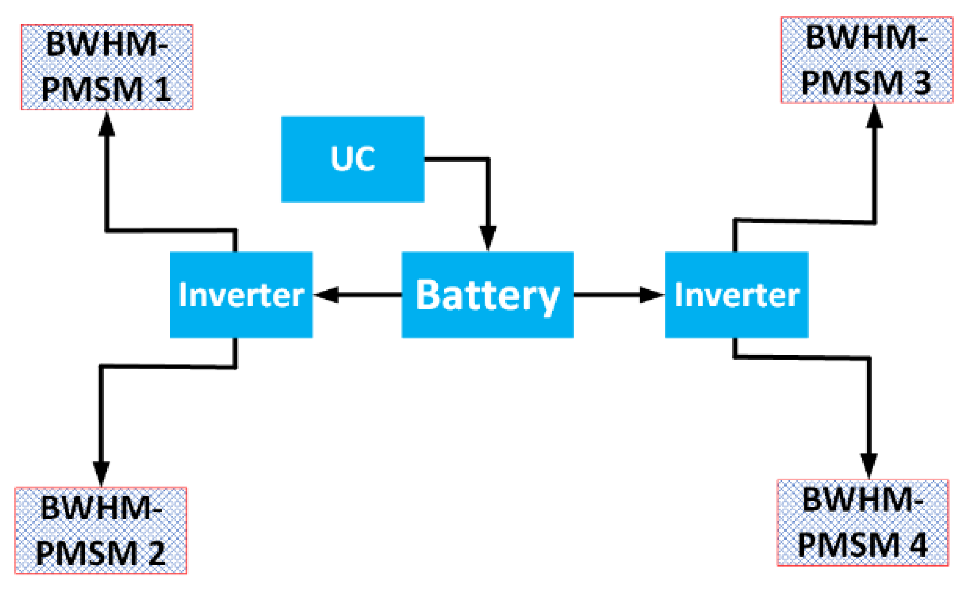
26] without considering the natural frequencies, as well as variable-speed analysis in some cases. This study demonstrates how these important considerations can change the choice of skewing angle. In addition to acoustic-based optimization, the electromagnetic performance of the motor, such as torque, cogging torque, and back-electromotive force(back-EMF) parameters, are defined as optimization constraints. We have derived the best skewing rate and slice number in order to reduce the vibration level power and maximum audible magnetic noise, while the electromagnetic performance remained constant. Finally, the multi-slice subdomain model (MS-SDM) optimized WHM-PMSM has numerically (3D-FEA) and experimentally verified the achievements for a fully electric vehicle car, in which the WHM-PMSM’s placement in the drivetrain is presented in
Figure 1. The battery and ultracapacitor are the primary and secondary energy sources of the drivetrain, respectively.
1.2. Paper’s Organization and Presentation
The paper is organized as follows. The introduction section brings some insights of the existing efforts on the analytical, semi-analytical, and numerical methods to compute the noise and vibration in the electric motors. In
Section 2, the analytical expressions of the PMSM related to the electromagnetic noise and vibration, based on the MS-SDM method is given.
Section 3 discusses both the numerical and graphical findings toward the objective that is noise and vibration reduction using skewing technique.
Figure 1 shows the WHM-PMSM in the powertrain.
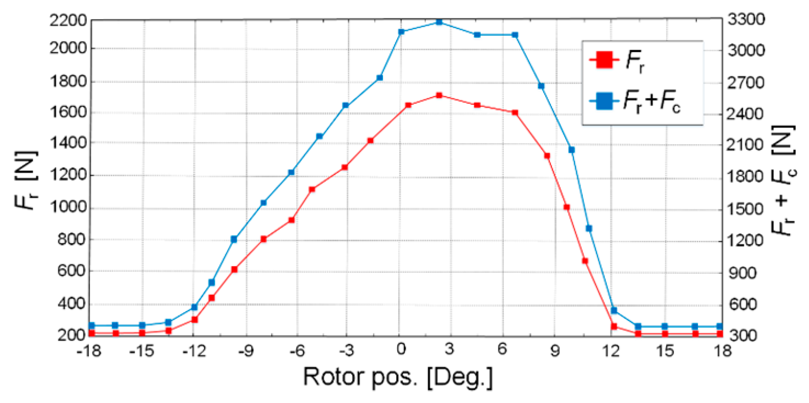
Figure 2,
Figure 3,
Figure 4,
Figure 5,
Figure 6 and
Figure 7 demonstrate several important electro-magnetic-based behaviors of WHM-PMSM, in which the magnetic noise is targeted on the MS-SDM simulation study results. In
Figure 2, the radial component of electromagnetic force is shown using MS-SDM.
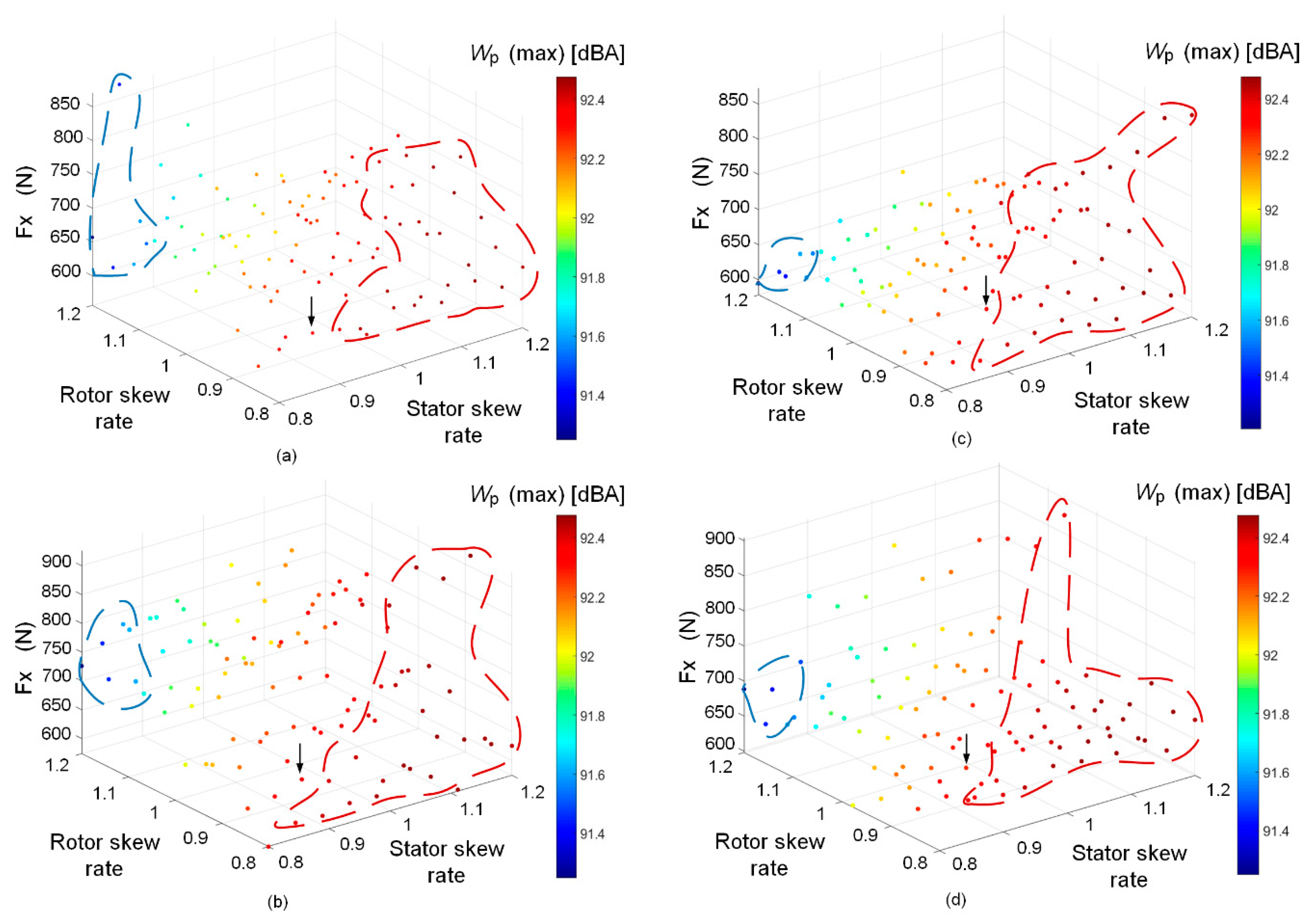
Figure 3 presents the impact of various skew angles of the stator and rotor on both the x-axis magnetic force and maximum sound power. Additionally, the effect of the skewing technique on the magnitude of the maximum sound power level with respect to the impactful modal contribution of the WHM-PMSM’s structure is presented in
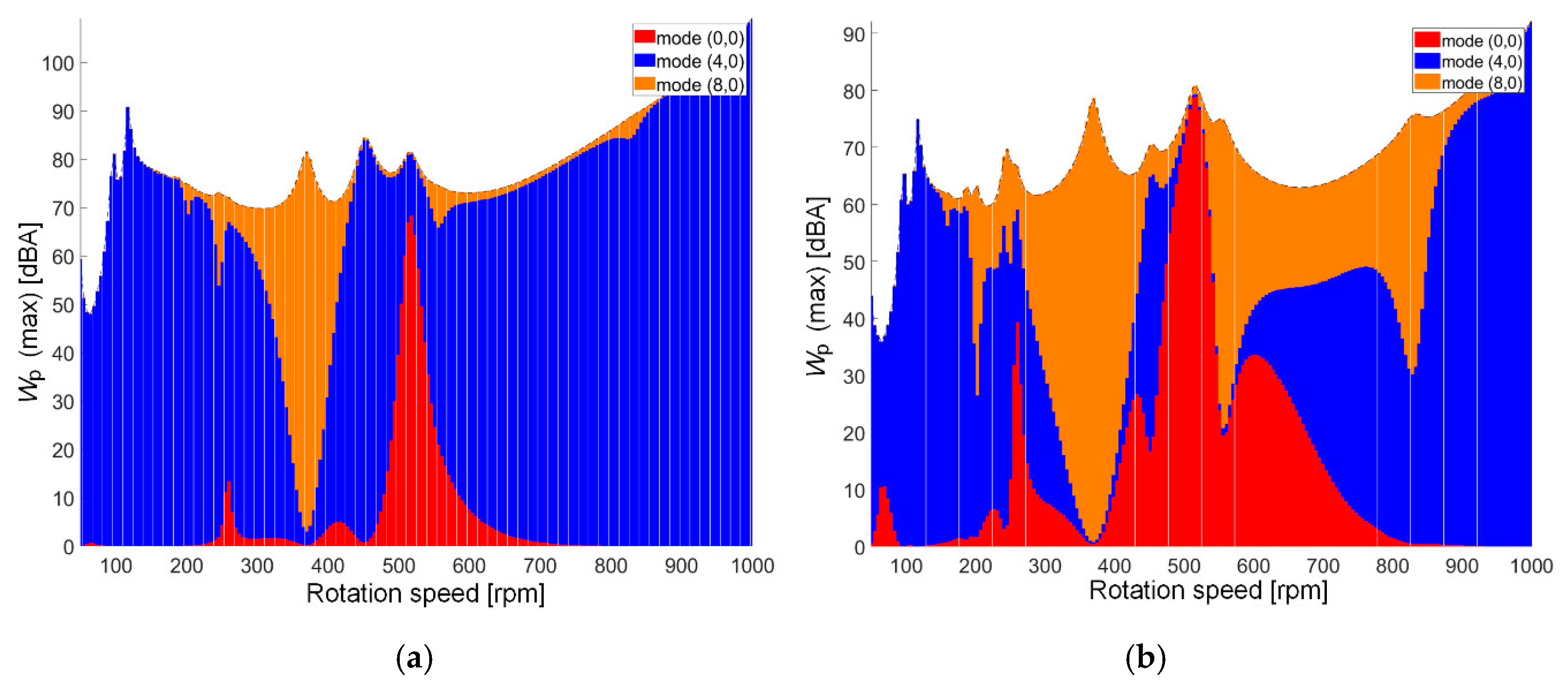
Figure 4.
Figure 5 and
Figure 6 reinforce the outcome of the numerical variable speed noise results by a 1/3 octave, A-weighted acoustic noise spectrum, and spectrum where the resonances are considered.
Section 4 validates the achievements using FEA and experimental measurement of the manufactured in-wheel PMSM.
Figure 8 and
Figure 9 verifies the MS-SDM using 3D FEA, and
Figure 10 and
Figure 11 validate the numerical-based results by experimental tests. Last, the conclusion offers the highlights and main achievements of the work.
2. Analytical Vibro-Acoustic Modelling Using Multi-Slice Subdomain Model (MS-SDM) for Wheel Hub-Mounted Permanent Magnet Synchronous Motor (WHM-PMSM)
Magnetic noise phenomenon consists of magnetostrictive and Maxwell forces. To calculate magnetic noise natural frequencies, the Fourier development of the PM is necessary by a permeance/ MMF model. This study has to consider the stator and rotor MMF; however, the rotor MMF is much smaller. The transient magnetic field for low frequency can be given by Maxwell’s equation:
where
Hj is magnetic field strength of the
jth subdomain slice,
Bj is magnetic flux density of each subdomain slice
jth,
E is electric field strength, and σ is electric conductivity. The skewing angle depending on the magnitude of the field can be discretized as follows [
7]:
where
is the magnitude of the field,
n denotes spatial order,
ω is the pulsation, and
θskew is the skew angle.
To compute the radial component of the force,
Fx and
Fy are defined based on the cylindrical coordinate system [
7]:
where both radial forces, which are basically produced by the stator and rotor winding harmonic magnetic field at
jth subdomain slice [
7], are:
Regarding the Maxwell stress tensor Equations (1)–(3), the radial magnetic force, as a major source of magnetic vibration and as a function of both space and time, can be defined as:
where
Azgj is the vector potential in the middle of air-gap for the
jth subdomain slice,
Frj is the radial magnetic force for the
jth subdomain slice,
Brj and
Btj are the radial and tangential components of magnetic flux density in the middle of air-gap
jth subdomain slice,
θ is the mechanical angular position,
n is the spatial harmonic order,
k is the time harmonic order,
ω is the angular velocity,
r is the radius of the rotor, and
m is the mass of rotor.
Fc is the centrifugal force.
Assuming that the stiffness and mass of the model are constant, when the machine is considered as time invariant, all the displacement and deformation should be calculated at each node of the generated meshes. Thereupon, the non-linear vibration of the
jth subdomain slice in the WHM-PMSM is [
7]:
Hence, the sound wave of the WHM-PMSM with a small amplitude is propagating for each
jth subdomain slice, which is a simplistic but useful idealistic homogeneous medium as:
The maximum sound power radiated for the
jth subdomain slice by the WHM-PMSM due to magnetic vibrations, which can be written as [
11,
12]:
where
Z0j denotes the air acoustic impedance,
Scj is the WHM-PMSM frame area at
jth slice, and
σmj is the modal radiation factor at
jth slice. The maximum sound power level
Wωj at
jth subdomain slice [
15] can be computed using:
The natural frequencies of the stator circumferential mode have been chosen only as even values due to the stator and rotor pole numbers both being even. Thus, the Maxwell exciting force harmonics are produced only as even spatial orders due to symmetry. By assimilating, the stator to an equivalent ring has been taken into account. The breathing mode natural frequency
f0 can be defined as [
16]:
where
a is the stator mean radius, which applies
hf as the frame width,
Kfsj is the stator stacking factor at
jth slice,
ρsj is the stator stack mass density at
jth slice, and Δ
m denotes the increasing mass because of the winding and teeth.
Following considerations and assumptions are made for the vibro-acoustic modeling using MS-SDM of WHM-PMSM with skewing:
Both stator and rotor are subjected to find the optimal angle of skew at each jth subdomain slice.
End effects are neglected because FSCW with non-overlapping configuration have very short end-windings at the studied WHM-PMSM.
Leakage flux in axial direction is ignored.
Main slotting magnetic forces wavenumbers and frequencies are considered.
The range of slice number j is 20 which means one slice per each 5 mm, in case of 100 mm stack length.
Variable speed analysis is targeted for the electromagnetic-acoustic performance of the WHM-PMSM.
The magnetic flux density along the axial axis is applied using 2D FEA for a higher accuracy.
The demagnetization characteristics of the permanent magnets are considered non-linear.
The analysis is done under load condition.
Natural frequencies are considered at variable speed analysis for the WHM-PMSM.
The saturation effect on the magnetic field is not considered by MS-SDM simulation (more details can be found in Reference [
7,
13,
26]).
3. Results and Discussion
The results and discussion section include the electro-magnetic impact of various skewing angles on the vibration and acoustic results with special attention on the audible magnetic noise and vibration computations. The input design data of the studied WHM-PMSM for the simulation is presented first.
Table 1 indicates this data in three individual sections, geometrical, electrical, and magnetic. The FE analysis is done using the potential vector method with the total time steps of 180, the number of elements of 544,289, and the number of nodes of 163,013. Each design case was simulated using nonlinear 3D FEA method. For both the initial and optimized designs, the PMs are made of NdFeB-N48 with a remanent flux density of 1.2 T, and the back irons are made of isotropic M400-50A non-orientated magnetic lamination steel with 7650 kg·m
−3. The elastic characteristics of the lamination is
Ex = 215 MPa,
Ey = 215 MPa, and
Ez = 80 MPa, besides, shear modulus is
Gxy = 82.7 MPa,
Gyz = 2 MPa, and
Gzx = 2 Mpa; the mechanical properties of the material used can be seen in
Table 1. All the following sections are based on 3D FEA unless specifically indicated otherwise.
Figure 2 illustrates the maximum radial magnetic force variation from Equations (1), (3) and (5) with and without centrifugal force consideration. As presented in the graph, the produced total (
j = 20) radial forces
Fr from the inner stator excited coils,
Fc, due to its mechanical essence, has a clockwise vector direction (based on the right’s hand law) because of the body’s inertia with a uniform distribution. Both the radial and centrifugal forces have a distribution with a radial vector direction and have an overlapped influence on each other. A summation of them, leading up to the resultant blue curve in this graph, indicates the total (or actual) radial force on the rotor.
The influence of various skew angles (as variables) is studied in the stator/ rotor, slot/ magnet pitch factors unit. Each single slot pitch factor, equal to 10°, from 0.8–1.2 (due to electromagnetic capability of the studied PMSM) on the
x-axis component of the magnetic force
Fx and A-weighted maximum sound power level
Wp,max (shown in
Figure 3) was calculated at variable speeds from
Nmin= 15 rpm to
Nmax = 1000 rpm. To find the best possible angle for each part (stator and rotor), this computation evaluates the impact of each variable on the objectives with respect to each other. Each graph is also a function of the number of skew slices.
Figure 3a presents two main regions (red and blue dashed areas) in which the red area is where the stator skew obtains the highest rate, between 1 to 1.2, whereas the rotor skew rate is lower. This area provides a higher level of
Wp,max, between 92.4 to 92.5 dBA. The lowest
Wp,max (optimal area) is reached when the highest rate of rotor skew angle (including magnets), and smaller stator angle skew were chosen (92.2 dBA). Comparing to the initial skew angle, which is analytically calculated (black arrow), an enhancement of approximately 1 dBA has been achieved. The analytical MS-SDM method used is based on the average flux density in 2D along the axial direction. Additionally, this graph (
Figure 3a) depicted the skew model by
j = 20 slices.
Figure 3b illustrates the optimal area as the same as
Figure 3a with ratings of 1.2 and 0.8 for the rotor and stator. However, a larger
Fx with skew slice of 20 in comparison with lower slice numbers, which produces consequently higher outputs, such as torque.
Figure 3c demonstrates how the odd number (15) of the skew slots again decreases
Fx by nearly 100 N. In this configuration,
Wp has been enhanced by 1.5 dBA when compared to the initial model. As presented in
Figure 3d, higher
Fx has been produced by maximum value of 874 N, when an even number (20) of skew slice has been used. Therefore, the importance of the skew slice number on
Fx and its harmonics are considerable with respect to the number of stator slots and rotor magnets (or slots, in case of other machine topologies) which can be an even or odd variable), has significant influence on the sound power level as function of speed. This figure helps in identifying number proportionally, although, it could not directly reduce
Wp.
Figure 4 reinforces the idea that the structural contribution of the WHM-PMSM skewing technique based on various range of skew angles, which is basically a structural-focused analysis of structural modes that are involved in airborne acoustic noise radiation of the studied PMSMs. Additionally, the acoustic noise level enhancement through cancelling the effect of a given structural mode to quantify the modal contribution to magnetic noise is targeted.
Figure 4a indicates the magnetic noise magnitude as function of speed, where the maximum radiated A- weighted magnetic noise of 91 dBA, can be seen at 124 rpm, however, this quantity is reduced using the optimized model (shown in
Figure 4b) by 16 dBA. The magnetic noise increases proportionally with the speed, and thus, the maximum sound power of 110 and 91.04 dBA can be reported for both the initial and optimized models. Although the force harmonic modes of (4,0) and (8,0) over the rotational speed range have contributed widely, the overall
Wp amplitude is decreased for the optimum skew angles, as shown in
Figure 4b.
Table 2 presents the main amplitudes of the MMF harmonics on both stator and rotor cores. As presented when the skew angles increase, the MMF harmonics (higher MMF harmonics results in higher force harmonics) of both cores are changing significantly. Higher rate of rotor skew angle brings a considerably lower MMF harmonic; however, a higher rate of stator skew angle has resulted in higher MMF harmonics and, finally, higher Wp. Moreover, the choice of best possible skew angles relies on other two important factors, resonance effect and electromagnetic capability. Hence, the final optimum values of both stator and rotor skew angles is provided through a trade-off. The fundamental harmonic (
h = 1) has its highest value at 1.2 rotor skew rate, which decreased slightly when the skew angle is decreased. The major harmonic orders, such as 3rd, 5th, and 7th, have shown lower harmonics, while the skew angle rates lower. The values are in per unit for a better comparison.
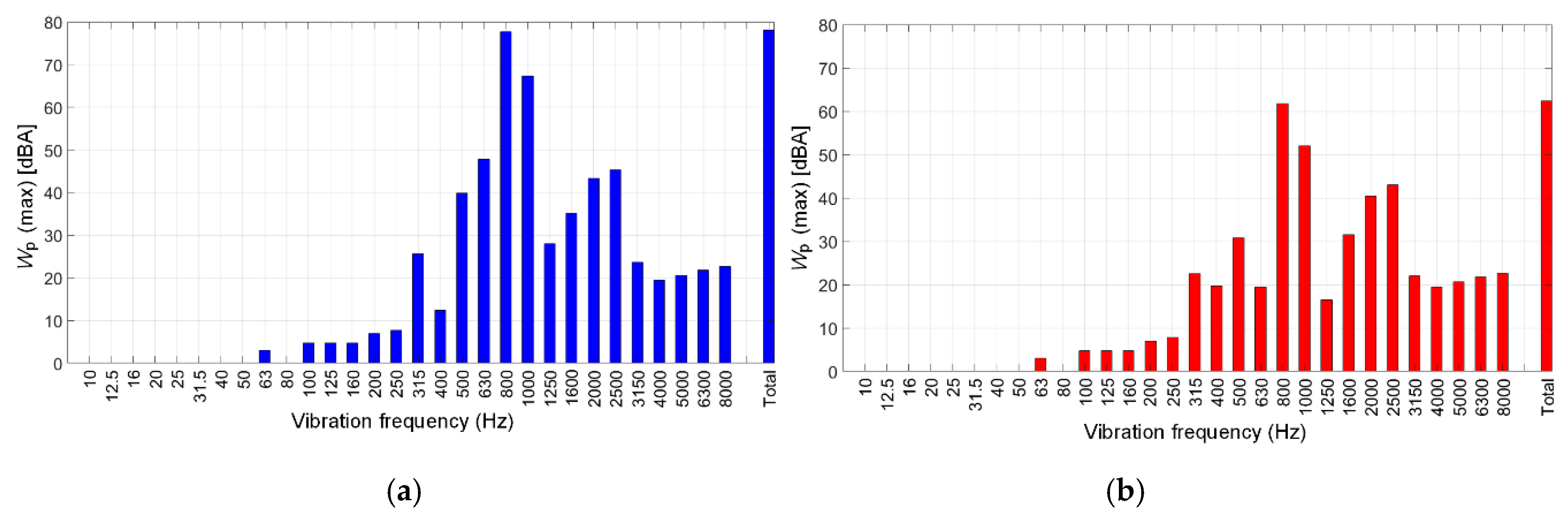
Figure 5 illustrates the one third octave A-weighted acoustic noise spectrum for the initial (
Figure 5a) and optimized (
Figure 5b) models. As presented, the maximum sound power bars based on the human’s normal audition for each range of frequencies are reduced using the skewing technique. The radiated magnetic noise at rated speed of 150 rpm on both initial and optimized PMSMs has obtained 78.08 and 62.67 dBA, respectively. Note that A-weighting was defined by IEC 61672-1:2013, which enables one to convert a physical quantity of acoustic pressure (in dB) into a psychoacoustic quantity (in dBA) that is supposed to better quantify how loud a noise is perceived.
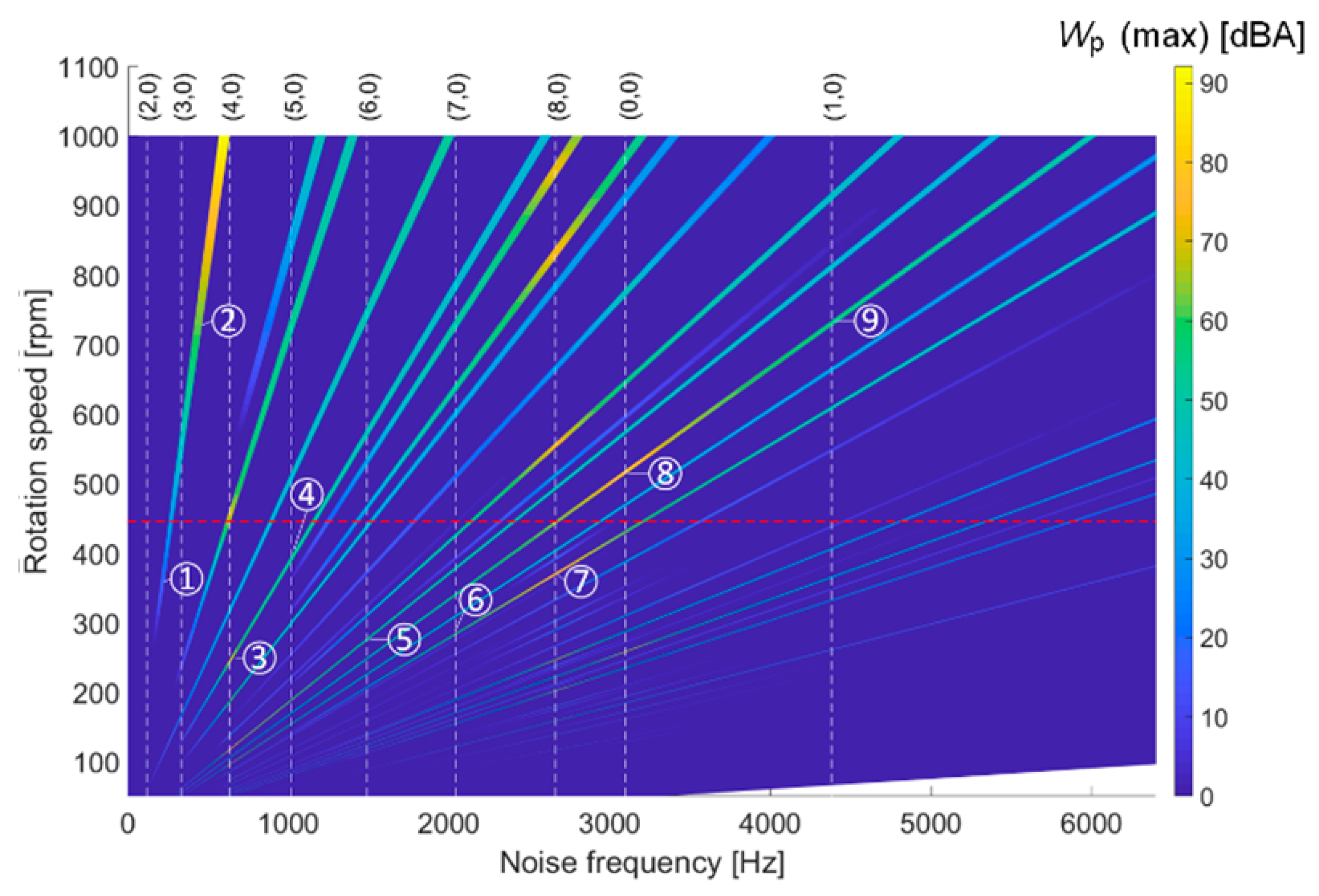
Figure 6 presents an A-weighted maximum magnetic noise spectrogram of the optimum skew angles of rotor and stator 12° and 8° under a variable speed range. The spectrogram is evaluated in the post processing stage, in which the electromagnetically-excited radial vibration illustration identifies whether the vibration resonances of variable speed of the WHM-PMSM due to magnetic forces occur during the operation or not. The designed WHM-PMSM allows to operate under 150 rpm, 50 Hz, while it is a motor.
Figure 6 presents that the first resonance happens at 185 Hz and 356 rpm which is shown between the grey dashed line in the modal structural modes of (2,0) and (3,0). The main slotting magnetic forces wavenumbers of r = 0, 4, and 8 are involved in the machine, where the magnetic forces wavenumbers by
is calculated in which the frequency is
, where
ks is an integer involved in permeance Fourier series, and ±ε varies between −1 to 1. There are two main resonances marked as 1 and 2, which have occurred at 172 Hz and 516 rpm, as well as 185 Hz and 554 rpm. In addition, the WHM-PMSM rotates in the flux weakening condition at 430 rpm which is indicated by the red dashed line. Afterwards, the largest 736 rpm, 488 Hz. Note that the first resonance at structural mode (2,0) happens when the electrical frequency of the traveling force wave of wavenumber r matches with the circumferential mode natural frequency, where 2 is the rank of the circumferential deflection, and 0 denotes the rank of the longitudinal deflection in the structural mode. To evaluate all the natural frequencies of the WHM-PMSM with rated speed of 15–150 rpm (0 to 50 Hz), the radial velocity in unit of dBA should be computed for over 5000 Hz.
4. FEA and Experimental Verifications
The stator contains 36 segmented teeth because of closed slot modulation in order to reduce the amplitude of cogging torque significantly. The proposed equations in the previous section explain how the resulting magnetic flux density distribution by a MS-SDM and 3D FE model with variable range analysis, in which the maximum flux density is around the stator teeth and the outer surface of stator.
Electromagnetic-Based Investigations
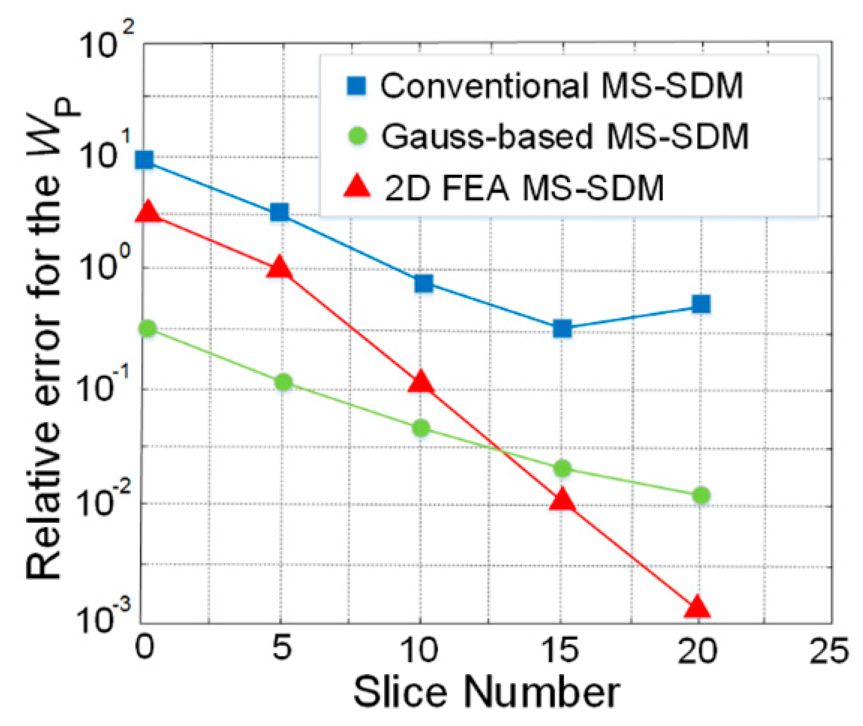
Figure 7 presents a comparison among three different MS-SDM methods, in which the largest relative error is reported for the conventional MS-SDM, where several significant assumptions are taken, such as axial leakage of the field. However, the methodology is fast. The second method uses Gauss points for the slice distribution of the model. It offers the lowest relative errors at under 15 slices and higher error for the 15 and 20 slices. The proposed method employed uses 2D FEA in MS-SDM, which stores B at each slice using FEA. This method shows a smaller relative error (10
−3) in higher number of slices, such as 10 to 20.
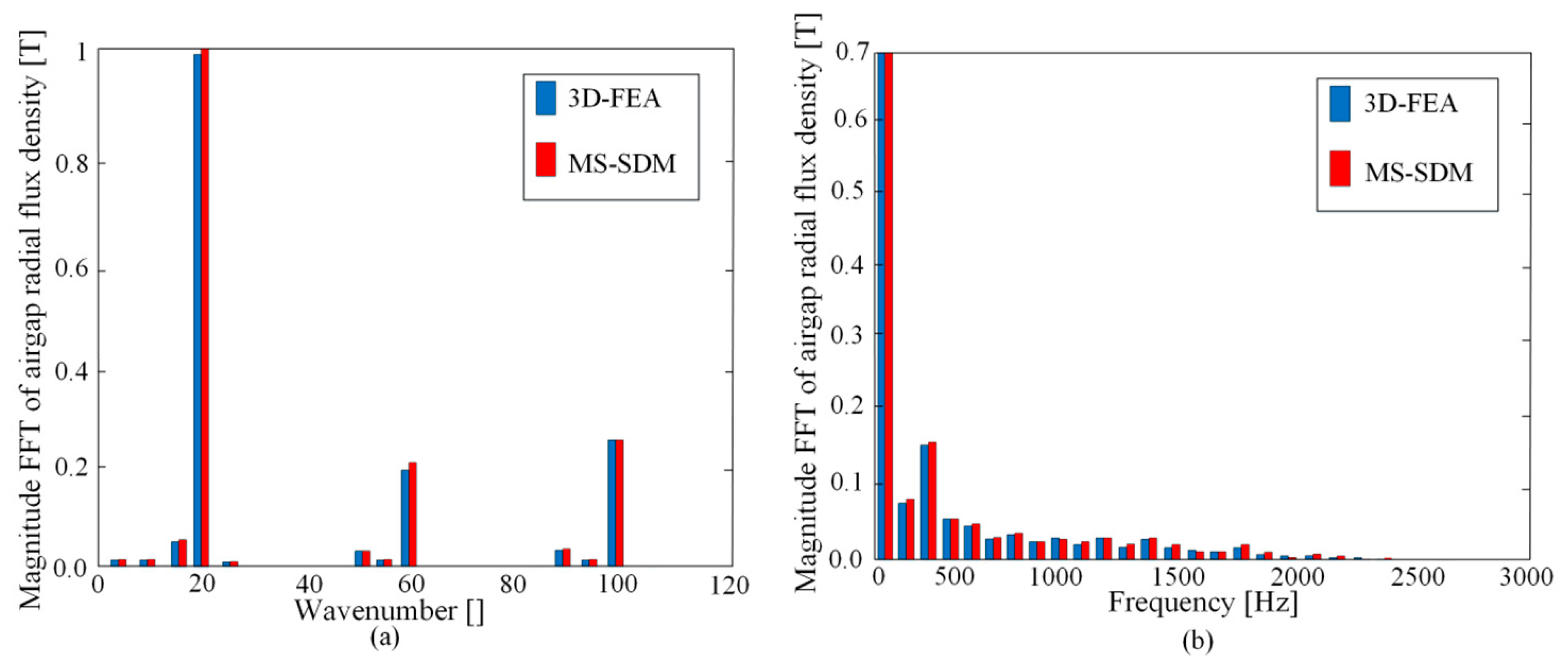
Figure 8 demonstrates a good agreement between MS-SDM and 3D-FEA models, where the harmonics as function of space (shown in
Figure 8a) and time (
Figure 8b) are compared. In
Figure 8a, the largest harmonic exists on wavenumber 20 (as the WHM-PMSM has 20 pole pairs). As the saturation effect on the magnetic field is not considered by MS-SDM simulation, thus, there are very small differences presented in
Figure 8a,b. The temporal harmonic contents on the flux is the same; however, the amplitude varies on the fundamental and the first harmonic. Indeed, the saturation is flattening the spatial distribution of magnetic flux such that the first harmonics are lower than the MS-SDM results.
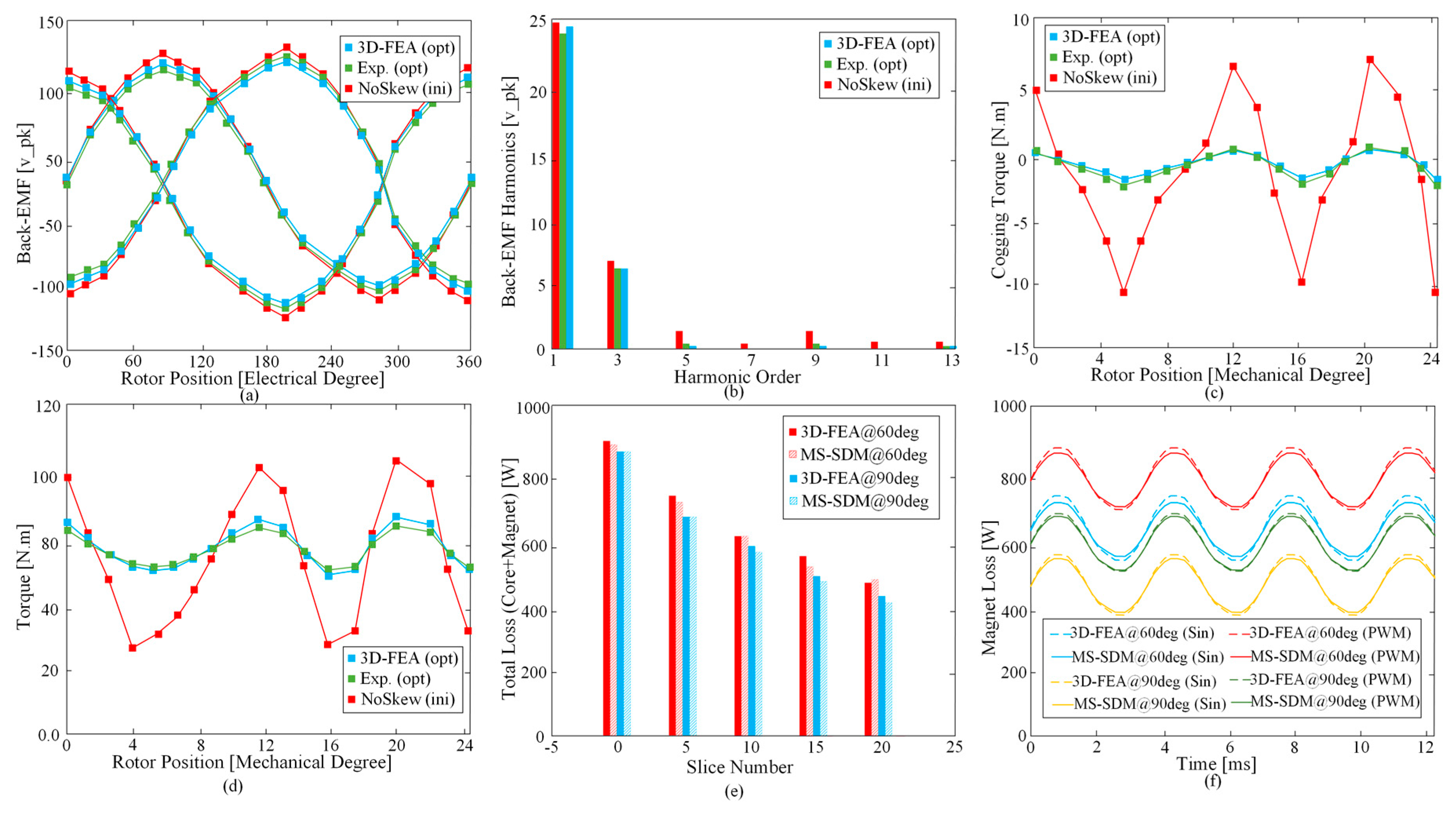
Figure 9 validates how the no-load electromagnetic main characteristics of the PMSM is varied between the initial model (ini) without skewing and optimized (opt) PMSM.
Figure 9a demonstrates three-phase balanced back-EMF waveforms produced from flux linkage rate of change over time, in every individual coil. As presented, the optimized PMSM’s back EMF is verified by experimental and FEA investigations.
Figure 9b presents the harmonic content of the back-EMF resulted from the fast Fourier transform analysis, it is shown that skewed PMSM model (opt) significantly reduced the harmonics mainly at higher orders, such as 5, 7, 9, 11, and 13. The reduction of fundamental harmonic (first order) due to skewing is experimentally measured by 3.5%. Although the peak-to-peak back-EMF is also slightly decreased, increasing the magnet thickness has compensated that loss which resulted in higher net magnet weight from 1.82 to 1.98 kg.
Figure 9c demonstrates how the skewing technique considerably quenches the peak-to-peak cogging torque for different rotor positions from 15 to 1.2 N.m. The electromagnetic instantaneous torque for initial and optimized PMSM (with 20 slices) is illustrated in
Figure 9d, where the skewing has suppressed the peak torque production by approximately 11 N.m. The torque ripple (
Tmax −
Tmin/
Tavg × 100) is also ideally decreased, in which the initial and optimum PMSMs have 9% and 7.9%, respectively. In
Figure 9e, the total loss as a function of slice number is provided, using MS-SDM and FEA simulations. The study reinforces that the slice number can reduce the total loss due to presence of high eddy-current loss at both iron cores and magnets. However, this modification comes with cost in the manufacturing stage; therefore, it is indeed an engineering trade-off among several factors, such as noise and vibration reduction and electromagnetic capability, as well as the manufacturing costs. In addition, the results show that the current phase angle affects the total core and magnet losses at certain armature current amplitude of 150A. The transient eddy-current loss produced at the magnets is simulated under different current angles of 60° and 90°. Additionally, the simulations indicate that PWM converter and sinusoidal supply can highly influence the amplitude of the magnet loss because of the harmonics injected by the PWM converter. The FEA-based simulation and experimental results verify that the semi-analytical MS-SDM approach is reliable for electromagnetic capabilities (including noise and vibration) predictions.
A modular system of Brüel & Kjær’s sound power kit is used, which is detailed in
Table 3, in which all component models are given.
To gather noise data of the WHM-PMSM under 150 rpm (rated speed), the PMSM was placed, based on ISO 6396. The microphone has been placed in radial direction of the rotor by 60 cm away from the PMSM to reduce the effect from the airflow, which are induced by the rotating rotor in an anechoic environment, which is shown in
Figure 10. This device allows for measuring sounds and noises with various frequency filters. In this assessment, one-third octave band filters are used because of the following advantage: higher accuracy due to lower effect of the ambient sounds and those noises which are known as external sources to the main noise source being measured. In addition, the vibration meter provides the needed data by FFT analysis. A high-performance vector control module (PI-PWM) from OMRON with the CIMR-A model is used for this experiment.
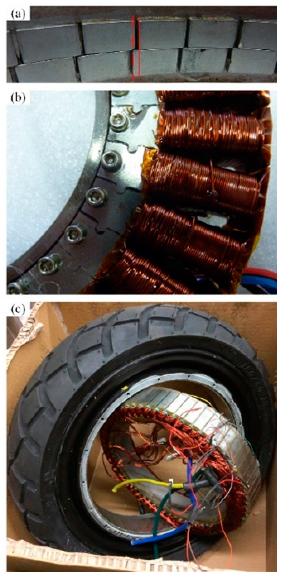
The manufactured prototype (shown in
Figure 11) with the optimum skew angles was tested for 5 kW power consumption.
Figure 11a,b presents the skewed magnets of the rotor and wounded stator core.
Figure 11c indicates the assembled wheel hub-mounted PMSM in the front wheel of the vehicle. The motor was electromagnetically optimized in another recent study, which can be found in Reference [
17].
A key feature is the Dyn-X technology, which avoids the need for input ranging via dual A/D converters to ensure you get the data the first time—when reaching an effective dynamic range of over 160 dB. This equipment operates as sample-synchronous phase alignment between all channels using IEEE 1588v2 precision time protocol (PTP) and GPS time synchronization. The measurement has been made in an anechoic room in order to avoid any external source of noise.
During the vibration test, the following physical-based magnitudes are measures for the studied WHM-PMSM, where depending on what the aim of the measurement is, some may be more appropriate to be considered:
- (a)
Displacement (frequency range of below 100 Hz).
- (b)
Speed (frequency range of 10 Hz to 1 kHz).
- (c)
Acceleration (high frequency measurement > 1 kHz).
The Rion vibration analyzer VA-12 allows precise vibration measurement by a piezoelectric accelerometer attached to a magnet. The meter provides an FFT analyzer measuring mode with both spectrum and time waveforms.
During the vibration test, the measuring instrument was set to provide an FFT analysis via acceleration measurements. The frequency span measured is over 5000 Hz to include high pass and low pass filters of 3 Hz and 20 kHz, respectively. Three measurement are done due to the x-axis, y-axis, and z-axis directions of vibration waves.
The presence of the magnetic noise produced in form of sound pressure level as a function of frequency is obtained at 15, 32, and 50 Hz.
Table 4 reports the influence of the different models with various values of skew angle and slice number on the electromagnetic capability of the PMSM.
Wvib,max shows the maximum magnitude of vibration in the defined speed range of 15–150 rpm, in which the vibration has reduced in the optimized model by 7.2 dB in comparison to initial model. Furthermore, small improvements can be reported for output power
Po, electromagnetic torque
T, efficiency
η, and constant power speed range constant-power-speed-range (CPSR). In addition, the fundamental
d-axis phase flux linkage
λm remains almost constant.
Figure 11 illustrates A-weighted sound pressure level (ASPL) as function of rotating speed (up to 1000 rpm). The blue curve presents the proposed WHM-PMSM model with peak value 65.8 dBA for speed range between 15–150 rpm, which has been experimentally verified by 78.6 dBA which is shown in the red color for the optimum skew angles and slice. In addition to the predicted and measured optimized model, the predicated initial model (in orange color) based on the empirical model is presented to highlight the improvement, where the peak radiated ASPL is 79.7 dBA under ratings operation. Note that the maximum ASPL over rating speed is above approximately 10 dBA. During the test, the rotor of the studied PMSM was coupled to an induction motor for deriving purpose, the induction motor itself produced between 5 to 15 dBA (these values are measured when the induction motor was operating without coupling with other machines) between 0–1000 rpm. Therefore, the error between predicted and measured curves is less than 3%. Two of the in-wheel motors used have the feature of generating regenerative power during the braking, therefore, the driver was employed to observe the regenerative mode. While the proposed WHM-PMSM was tested the driver was in open-circuit condition because of its sole positive acceleration (motoring) characteristic.
The experimental measurement was conducted in the laboratory of Electrical Machines and Drives at Universitat Politècnica de Catalunya-Barcelona Tech. The environmental impact was carefully considered. In fact, noise pollution persistency in any form of vibrations and audible noise in residential or industrial ranges are harmful and can even cause health issues to anyone who is near the sources.
5. Conclusions
A light-duty electric vehicle equipped with four in-wheel hub-mounted PMSMs, in which even integer slot number (in this case 36) has empirically resulted in only even force wavenumbers (0, 2, or 4) of Maxwell force harmonics, which literally avoids an unbalanced magnetic force (the net electromagnetic force in the stator). However, all the wavenumbers should be considered via a variable-speed computation of electromagnetically-excited noise to give a precise prediction of the vibro-acoustic outcome. In this research, the audible magnetic noise radiated under different angles of both stator and rotor skews were examined for a variable-speed analysis using MS-SDM to find the best skew angle and slice number, which minimizes the sound power, while the electromagnetic capability of the machine remains constant. The impact of the motor’s natural frequencies was also considered to avoid resonance when the motor operates under defined ratings. For considering all the possible resonances which might occur in this WHM-PMSM with (5–50 Hz), the variable speed range of over 5000 Hz vibration frequency has been used and has been presented in the acoustic sonograms. Finally, the WHM-PMSM with optimal skew angles and slice number have reduced the maximum sound pressure and power levels by 10 dBA and 5 dBA (in average), when the motor operates under ratings (150 rpm in this case). Due to lower force harmonics, this improvement is reached by the optimum skew angles in the stator and rotor cores. Additionally, the skew slice number of 20 was chosen due to its contribution on the net electromagnetic force, which indirectly has small effect on the resulted sound power, approximately less than 1 dBA. From a manufacturing point of view, the slice number of 20 is expensive, and the prototyped WHM-PMSM is manufactured using 20 slices to validate the e-NVH numerical achievements. The study also presented that a slice number between 10 to 15 offers a reasonable reduction of e-NVH with an acceptable relative error, in addition to an inexpensive manufacturing of both stator and rotor parts. The choice of slice number is a trade-off between cost and electromagnetic benefits that, depending on the application requirements, can be tolerated. For traction motors, the overall recommendations of the study are the skewing angle of 12° and 8° for rotor and stator cores, and a slice number between 5 to 15 are suggested. All the computations have been numerically (3D-FEA) and experimentally verified through magnetic noise measurements with a small error.
