Article

Transmit Power Optimization for Intelligent Reflecting Surface-Assisted Coal Mine Wireless Communication Systems

School of Communication and Information Engineering, Xi’an University of Science and Technology, Xi’an 710054, China
*
Author to whom correspondence should be addressed.
Submission received: 22 July 2025 / Revised: 16 September 2025 / Accepted: 23 September 2025 / Published: 25 September 2025

Abstract

The adverse propagation environment in underground coal mine tunnels caused by enclosed spaces, rough surfaces, and dense scatterers severely degrades reliable wireless signal transmission, which further impedes the deployment of IoT applications such as gas monitors and personnel positioning terminals. However, the conventional power enhancement solutions are infeasible for the underground coal mine scenario due to strict explosion-proof safety regulations and battery-powered IoT devices. To address this challenge, we propose singular value decomposition-based Lagrangian optimization (SVD-LOP) to minimize transmit power at the mining base station (MBS) for IRS-assisted coal mine wireless communication systems. In particular, we first establish a three-dimensional twin cluster geometry-based stochastic model (3D-TCGBSM) to accurately characterize the underground coal mine channel. On this basis, we formulate the MBS transmit power minimization problem constrained by user signal-to-noise ratio (SNR) target and IRS phase shifts. To solve this non-convex problem, we propose the SVD-LOP algorithm that performs SVD on the channel matrix to decouple the complex channel coupling and introduces the Lagrange multipliers. Furthermore, we develop a low-complexity successive convex approximation (LC-SCA) algorithm to reduce computational complexity, which constructs a convex approximation of the objective function based on a first-order Taylor expansion and enables suboptimal solutions. Simulation results demonstrate that the proposed SVD-LOP and LC-SCA algorithms achieve transmit power peaks of 20.8 dBm and 21.4 dBm , respectively, which are slightly lower than the 21.8 dBm observed for the SDR algorithm. It is evident that these algorithms remain well below the explosion-proof safety threshold, which achieves significant power reduction. However, computational complexity analysis reveals that the proposed SVD-LOP and LC-SCA algorithms achieve O ( N 3 ) and O ( N 2 ) respectively, which offers substantial reductions compared to the SDR algorithm’s O ( N 7 ) . Moreover, both proposed algorithms exhibit robust convergence across varying user SNR targets while maintaining stable performance gains under different tunnel roughness scenarios.

1. Introduction

The complex structure and environment in the coal mine tunnel result in path loss, absorption attenuation, and multi-path effects during signal propagation, which significantly degrades wireless transmission reliability and consequently impairs the data collections and command interactions for IoT devices [1]. To alleviate signal attenuation, increasing transmit power is a common approach. However, for the coal mine wireless communication system, the explosion-proof safety transmission power threshold is stipulated to not exceed 6 W (i.e., 37.8 dBm ) due to the fact that higher-power radio waves may ignite gas and coal dust [2]. In addition, most IoT devices deployed in underground coal mines, such as monitoring terminals, are battery-powered and highly energy-constrained [3]. Therefore, transmit power optimization becomes essential to address these requirements. The beamforming technology is a critical approach for achieving the minimum transmit power (MiniPower) by adjusting the phase and amplitude of the antenna array at the transmitter to make the signal energy add coherently for a particular receive direction [4]. However, due to the limitations of the base station (BS) deployment locations and the complex wireless propagation characteristics in coal mine tunnels, the beam from the transmitter is difficult to reach the desired target location [5]. Therefore, how to minimize the transmit power while ensuring communication quality has become a challenging problem for wireless communication systems in coal mines.
As one of the promising technologies for sixth-generation (6G) wireless networks, an intelligent reflecting surface (IRS) composed of a large number of low-cost passive reflecting elements can offer advantages such as low energy consumption, low cost, and ease of deployment [6,7]. Herein, IRS passive beamforming technology can achieve the directional signal transmission through the control of passive reflection units. Specifically, each IRS passive element can independently reflect the incident signal by controlling its amplitude and/or phase to realize coherent superposition of the reflected signals in the target direction, which can overcome the limitations of traditional beamforming that rely on a finite number of antennas. To ensure the minimal transmit power, the prevailing approaches for MiniPower problems mainly focus on the joint optimization of beamforming at the BS and IRS phase shifts in IRS-assisted communication systems [8,9,10,11,12,13,14,15].
In [8], the MiniPower problem in IRS-aided single-user wireless communication systems can be solved by applying the semidefinite relaxation (SDR) technique and obtaining a high-quality approximate solution. They also proposed a two-stage algorithm and alternating optimization (AO) algorithm to obtain suboptimal solutions that can offer different trade-offs between performance and complexity for the multiuser scenario. In [9], IRS-assisted multiple-input multiple-output (MIMO) systems are further investigated, which demonstrates that the introduction of IRSs can reduce the transmit power to less than 50 % compared by the conventional systems without IRS while maintaining communication quality. For IRS-assisted non-orthogonal multiple access (NOMA) systems, a closed-form expression of IRS phase shifts can be derived by a low-complexity beamforming design method based on Karush–Kuhn–Tucker (KKT) optimal conditions in [10]. Moreover, the MiniPower problem also appears in other scenarios. In IRS-assisted uplink Internet of Things (IoT) networks, the Riemannian manifold-based alternating optimization (RM-AO) algorithm has been employed to minimize users’ uplink transmit power by jointly optimizing IRS phase shifts, and base stations (BSs) receive beamforming [11]. In [12], for IRS-assisted physical-layer broadcast communication systems, an alternating optimization algorithm based on SDR and successive convex approximation (SCA) is adopted to optimize and minimize the BS’s transmit power while satisfying the QoS constraints of each piece of mobile equipment (ME). Their works demonstrated joining traditional beamforming and IRS passive beamforming technology to achieve better network resource allocation on the roadbed. Moreover, a large amount of work [16,17,18] has verified that the passive operation, low power consumption, ease of deployment, and cost-effectiveness of the IRS make it particularly suitable for coal mine tunnels where there are strict safety regulations for electrical equipment. Nevertheless, the application of IRS passive beamforming technology still poses great challenges for the complex environment and stringent power constraints in coal mines.
In this paper, we propose a singular value decomposition-based Lagrangian optimization (SVD-LOP) algorithm to minimize the transmit power at the mining base station (MBS) for IRS-assisted coal mine wireless communication systems. Firstly, considering the characteristics of rough tunnels and dense coal dust scatterers, we propose a three-dimensional twin cluster geometry-based stochastic model (3D-TCGBSM) system model to characterize a rectangular coal mine tunnel communication assisted by IRS. On this basis, a non-convex MiniPower problem constrained by user SNR target and IRS phase shifts is formulated. To solve this problem, we propose an SVD-LOP algorithm by performing the SVD and introducing the Lagrange multipliers to obtain the optimal solution. To reduce computational complexity, we further propose a low-complexity successive convex approximation (LC-SCA) algorithm via the first-order Taylor formula and polarization processing to successively approximate the objective function and obtain the suboptimal solution. Simulation results demonstrate that the proposed SVD-LOP algorithm achieves superior power optimization performance compared to SDR before peak power while maintaining comparable performance thereafter. The proposed LC-SCA algorithm also outperforms SDR before the peak and then slightly degrades after the peak. Furthermore, both proposed algorithms exhibit significantly lower computational complexity, O ( N 3 ) for SVD-LOP and O ( N 2 ) for LC-SCA, compared to the O ( N 7 ) complexity of the SDR algorithm. In addition, the proposed algorithms consistently outperform SDR under varying user SNR targets and different tunnel roughness scenarios.

2. System Model and Channel Modeling

2.1. System Model

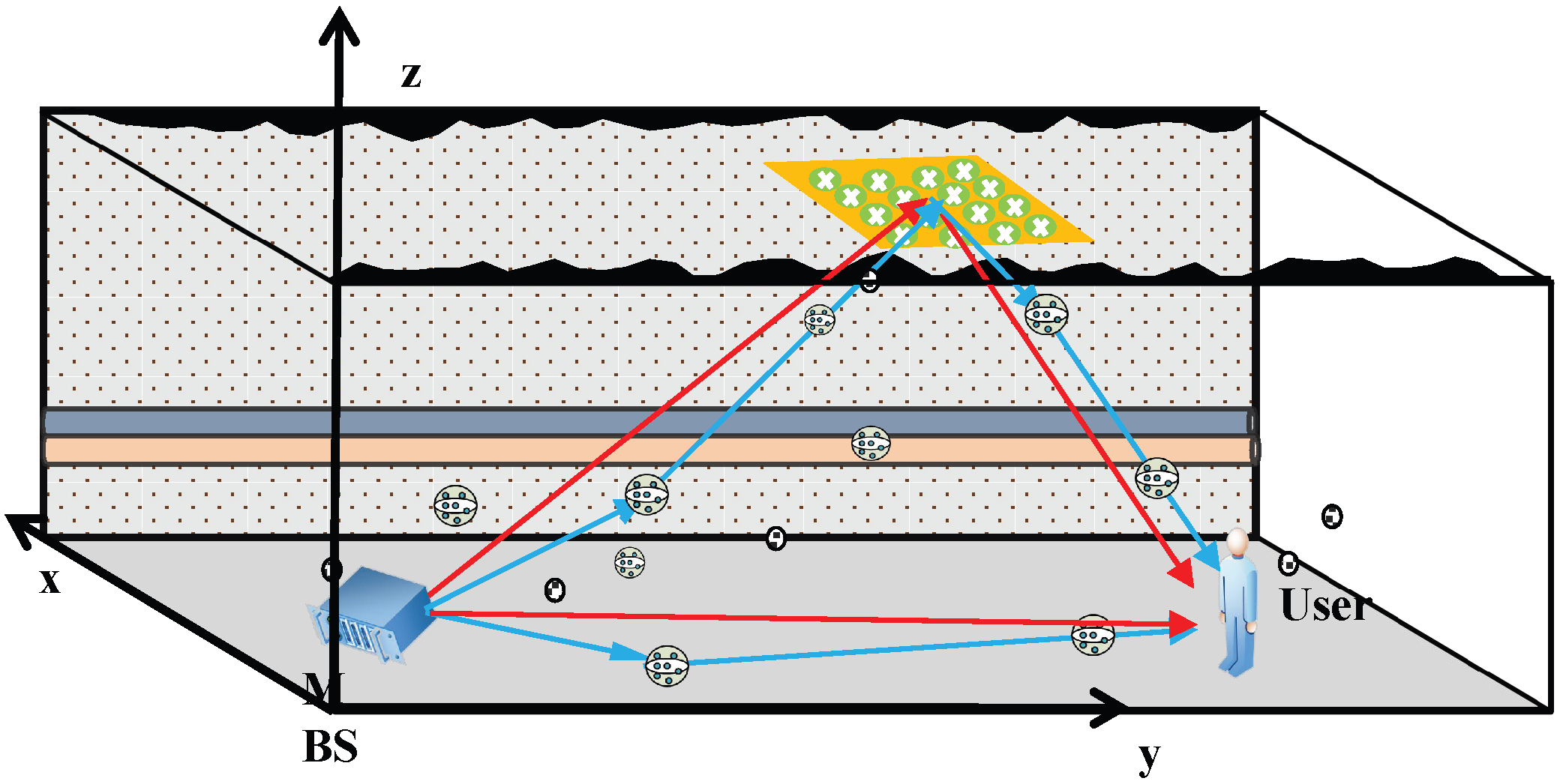
In the enclosed rectangular coal mine tunnel, the randomly distributed scatterers and the rough tunnel surfaces create unique and challenging channels. In particular, the abundant scatterers lead to multibounce multipath components (MMCs) that constitute a dominant portion of the complete channel impulse response. Meanwhile, the rough tunnel surface induces significant signal scattering, attenuation, and multipath propagation, which complicates the wireless transmission characteristics. To capture these essential channel characteristics, we propose the 3D twin-cluster geometry-based stochastic model depicted in Figure 1, where an MBS equipped with K antennas communicates with a single antenna user assisted by an IRS. The IRS is composed of N passive reflecting elements in a rectangular plane, where each element is capable of reflecting the incident signal and has a separate reflection coefficient. The downlink channels between the MBS and user comprises both line-of-sight (LoS) and non-line-of-sight (NLoS) propagation paths, where each path is composed of direct links (red lines) and reflected links (blue lines). Specifically, MMCs and the multipath propagation caused by rough surfaces are categorized into virtual reflected links. In addition, it is assumed that the channel state information (CSI) of all channels is completely known at MBS. As in most conventional configurations widely adopted in the literature [8,9,10], we assume that the antenna orientation has already been pre-configured to its optimal state, and the electromagnetic wave propagation is aligned toward the receiver. Accounting for the mobility of scatterers, the channel matrices from MBS to IRS, IRS to user, and MBS to user are characterized as H M I ( t , f ) C N × K , H I U ( t , f ) C N × 1 and H M U ( t , f ) C K × 1 , respectively. Here, t denotes the delay of clusters, and f represents the operating frequency. Assuming ideal IRS phase shifts, the cascaded channel between MBS and user aided by IRS can be superposed on the MBS–user direct link to construct equivalent channel between MBS and user. It can be expressed as
H = H M U H + H I U H Q H M I ,
where Q is the IRS reflection coefficient matrix. Define it as a diagonal matrix Q = β n diag ( e j θ 1 , , e j θ N ) , in which θ n [ 0 , 2 π ] and β n = 1 denote the phase shifts and amplitude reflection coefficient of the n-th reflecting element.

2.2. Channel Modeling

For clear spatial analysis, we model the system in a geometric coordinate framework, as illustrated in Figure 2. Denote the channel matrix between MBS and IRS as H M I ( t , f ) = [ h n k M I ( t , f ) ] N × K , where h n k M I ( t , f ) represents the channel impulse response between n-th reflecting element of IRS and the k-th antenna of MBS. Since each channel impulse response is defined as a weighted sum of the LoS component and the NLoS component [19], h n k M I ( t , f ) can be expressed as
h n k M I ( t , f ) = K K + 1 h n k M I , L ( t , f ) + 1 K + 1 h n k M I , N L ( t , f ) ,
where K is the Rician factor.
The LoS component h n k M I , L ( t , f ) be given by
h n k M I , L ( t , f ) = C 0 ( ξ n k M I , L ) 2 σ · e j 2 π τ n k M I , L ( t ) ( f c f ) ,
where C 0 represents the path loss for propagation distance of 1 m, σ is the standard deviation of additive white Gaussian noise (AWGN). ξ n k M I , L is the distance between n-th reflecting element of IRS and the k-th antenna of MBS, τ n k M I , L ( t ) represents the delay of the LoS component denoted as τ n k M I , L ( t ) = ξ n k M I , L / c , and c is the speed of light.
For NLoS component h n k M I , N L ( t , f ) , it can be expressed as
h n k M I , N L ( t , f ) = g = 1 G ( t ) r = 1 R g C 0 ( ξ n k , r g M I , N L ( t ) ) 2 σ · P n k , r g ( t ) · e j 2 π f c τ n k , r g M I , N L ( t ) ( f c f ) · e j Δ ϕ r g · ρ s ν .
where G ( t ) denotes the number of scattering clusters. R g is the number of rays within the g-th scattering cluster. ξ n k , r g M I , N L ( t ) is the geometric distance for the r-th ray of the g-th cluster between MBS and IRS. P n k , r g ( t ) and τ n k , r g M I , N L ( t ) represent the normalized power and propagation delay for the r-th ray of the g-th cluster. Δ ϕ r g and ρ s ν are the phase difference related to the rough tunnel walls and the roughness attenuation factor. Detailed descriptions can be found in [17].
Similarly, the channel matrix between IRS and user is denoted as H I U = h n I U ( t , f ) N × 1 , where the corresponding channel impulse response h n I U ( t , f ) between the n-th reflecting element of the IRS and user can be expressed as
h n I U ( t , f ) = K K + 1 h n I U , L ( t , f ) + 1 K + 1 h n I U , N L ( t , f ) ,
where
h n I U , L ( t , f ) = C 0 ( ξ n I U , L ) 2 σ · e j 2 π τ n I U , L ( t ) ( f c f ) ,
and
h n I U , N L ( t , f ) = g G ( t ) r = 1 R g C 0 ( ξ n , r g I U , N L ( t ) ) 2 σ · P n , r g ( t ) · e j 2 π f c τ n , r g I U , N L ( t ) ( f c f ) · e j Δ ϕ r g · ρ s ν .
The channel matrix between IRS and user is written as H M U = h k M U ( t , f ) K × 1 , where the channel impulse response h k M U ( t , f ) from the k-th antenna to user can be expressed as:
h k M U ( t , f ) = K K + 1 h k M U , L ( t , f ) + 1 K + 1 h k M U , N L ( t , f ) ,
where
h k M U , L ( t , f ) = C 0 ( ξ k M U , L ) 2 σ · e j 2 π τ k M U , L ( t ) ( f c f ) ,
and
h k M U , N L ( t , f ) = g G ( t ) r = 1 R g C 0 ( ξ k , r g M U , N L ( t ) ) 2 σ · P k , r g ( t ) · e j 2 π f c τ k , r g M U , N L ( t ) ( f c f ) · e j Δ ϕ r g · ρ s ν .

3. Problem Formulation and Optimization Solution

3.1. Problem Formulation

Taking into account both the MBS–user and MBS–IRS–user paths, the received signal at user is expressed as
y = ( H M U H + H I U H Q H M I ) w s + n ,
where n N ( 0 , σ 2 ) is the additive white Gaussian noise (AWGN) at user. We denote the transmitted signal at MBS can be written as x = w s , where s is the transmitted data and normalized power E [ | s | 2 ] = 1 . w C K × 1 denote the transmit beamforming vector from MBS to user. Based on this, the signal-to-noise ratio (SNR) of user is defined as
SNR = | H M U H + H I U H Q H M I w | 2 σ 2 ,
In this paper, our goal is to minimize transmit power at MBS by jointly optimizing the transmit beamforming at MBS and the passive reflective beamforming of IRS phase shifts with the given constraints of user SNR. Accordingly, the problem is formulated as
( P 1 ) : min w , θ w 2
          s . t . | H M U H + H I U H Q H M I w | 2 σ 2 γ ,
            0 θ n 2 π , n = 1 , , N .
where P is the transmit power at MBS written by P = | | w | | 2 , and γ is the minimum user SNR target. Due to the deep coupling of the optimization variables θ n , w and P within the SNR constraint, the (P2) is non-convex.
In the single-user setup, the active beamforming w applies the conventional continuous linear precoding to achieve the adjustment of signal phase. It is worth noting that when the IRS phase shifts are fixed, the equivalent single-user channel H is rank-1. In this case, maximum ratio transmission (MRT) is the optimal beamforming strategy that achieves the target SNR with the minimum transmit power among all feasible solutions [8]. Therefore, for any given IRS phase shift θ , the maximum ratio transmission (MRT) is recognized as the optimal transmit precoder for (P1), i.e., w * = P H M U H + H I U H Q H MI H H M U H + H I U H Q H MI . By substituting w * into (P1), the (13) is equivalent to maximizing the channel power gain of the combined user channel, that is,
( P 2 ) : max θ H M U H + H I U H Q H M I 2
     s . t . 0 θ n 2 π , n { 1 , , N } .
Let v = [ v 1 , , v N ] H where v n = e j θ n , n . Thus, the constraints in (17) are equivalent to the unit-modulus constraints: | v n | 2 = 1 . By applying a change in variables H I U H Q H M I = v H Φ , the combined channel is Φ = diag ( H I U H ) H M I C N × K . Therefore, (P2) can be expressed as
( P 3 ) : max θ H M U H + v H Φ 2
    s . t . | v n | 2 = 1 , n { 1 , , N } .
Although simplified by the optimal transmit beamforming w * , (P3) exhibits highly non-convex characteristics, and the unit modulus constraints form a non-convex feasible region. Therefore, the non-convexity of constraints remains the primary challenge in the optimization problem. In next section, we propose two algorithms to obtain the optimal and suboptimal solutions to (P3), respectively.

3.2. Optimization Solution

3.2.1. Singular Value Decomposition-Based Lagrangian Optimization Algorithm

In coal mine tunnels, the presence of numerous scatterers result in complex multipath fading. According to the principle of wave superposition, multipath fading causes fluctuations in signal amplitude and phase shifts, which results in frequency-varying stochastic characteristics in the combined channel Φ . This impacts the spatial correlation and singular value distribution statistical properties of this channel Φ . Consequently, we apply singular value decomposition (SVD) to decompose the combined channel Φ , which is particularly crucial for coal mine communication to handle complex channel or signal characteristics [20]. The SVD of the combined channel Φ can be represented as
Φ = U Σ Y H
where U C N × N and Y C K × K are unitary matrices (i.e., U H U = I , Y H Y = I ). Σ C N × K is a diagonal matrix with singular values σ 1 , σ 2 , , σ min ( N , K ) arranged in descending order along its diagonal. Therefore, (18) can be written by H M U H + v H U Σ Y H 2 through SVD. To simplify this expression, we define a new variable z H = v H U . Since U is a unitary matrix and | v n | 2 = 1 , z = [ z 1 , z 2 , , z N ] T still satisfies the unit modulus constraint | z n | 2 = 1 , (P3) can be expressed by
( P 4 ) : max θ H M U H + z H Σ Y H 2
    s . t . | z n | 2 = 1 , n { 1 , , N } .
This is still a non-convex optimization problem. For solving (P4), we do not aim to convexify the problem. Instead, we decompose the structure of the problem using the Lagrange multiplier method, transforming the complex coupled constraints into an iteratively solvable optimization problem. However, the effectiveness of the Lagrange multiplier method is fundamentally determined by the specific property and inherent condition of the problem, as follows. Firstly, the (21) in terms of z is constructed via linear operations on complex vectors. According to the theory of complex functions, (21) is continuously differentiable within its domain. Secondly, as the θ n in v n = e j θ n is linearly independent, the gradient vectors of the constraints | z n | 2 = 1 (for n = 1 , , N ) also preserves this property, which satisfies the Robinson condition to support algorithm solution via Lagrange multipliers and ensure constraint system regularity [21].
Firstly, by expanding (21) according to the distributive law of matrix multiplication, we can obtain
H M U H + z H Σ Y H 2 = H M U H + z H Σ Y H H M U H + z H Σ Y H H = z H Σ Y H Y Σ H z + z H Σ Y H H M U + H M U H Y Σ H z + H M U H H M U = z H Σ Σ H z + z H Σ Y H H M U + H M U H Y Σ H z + H M U H H M U ,
where, since H M U H H M U is independent of z , it can be omitted. Based on this, we introduce the Lagrange multipliers λ n and transform (P4) into minimizing the negative of the objective function, that is
L ( z , λ ) = z H Σ Σ H z Quadratic 2 Re { z H Σ Y H H M U } Linear + n = 1 N λ n ( | z n | 2 1 ) Constraint penalty .
Next, we need to take the derivative of Equation (24). Since z n is the n-th element of z , the constraint penalty term becomes | z n | 2 1 = z n z n * 1 . For subsequent derivation, we compute the gradient relative to z * . By Wirtinger calculus, z and z * can be regarded as independent variables, and the derivative with respect to z * equals taking derivatives for each z n * . The derivative of the constraint penalty term with respect to z * is given by
z * n = 1 N λ n ( z n z n * 1 ) = λ 1 z 1 λ 2 z 2 λ N z N = Λ z ,
where Λ = diag ( λ 1 , , λ N ) . Therefore, the derivative of the Equation (26) is written as:
L ( z , λ ) z * = Σ Σ H z Σ Y H H M U + Λ z ,
Let Equation (26) be equal to zero, we have ( Σ H Σ Λ ) z = Σ Y H H M U . Due to Σ Σ H = diag ( σ 1 2 , σ 2 2 , , σ N 2 ) and Λ being diagonal matrices, this equation can be decoupled into the following element-wise representation:
( σ n 2 λ n ) z n = ( Σ Y H H M U ) n
Note that | z n | = 1 (i.e., z n z n * = 1 ), λ n can be expressed as
λ n = σ n 2 + Re ( ( Σ Y H H M U ) n z n * )
Similarly, z n can be expressed as
z n = e j ϕ n , ϕ n = [ Σ Y H H M U ] n | σ n 2 λ n | .
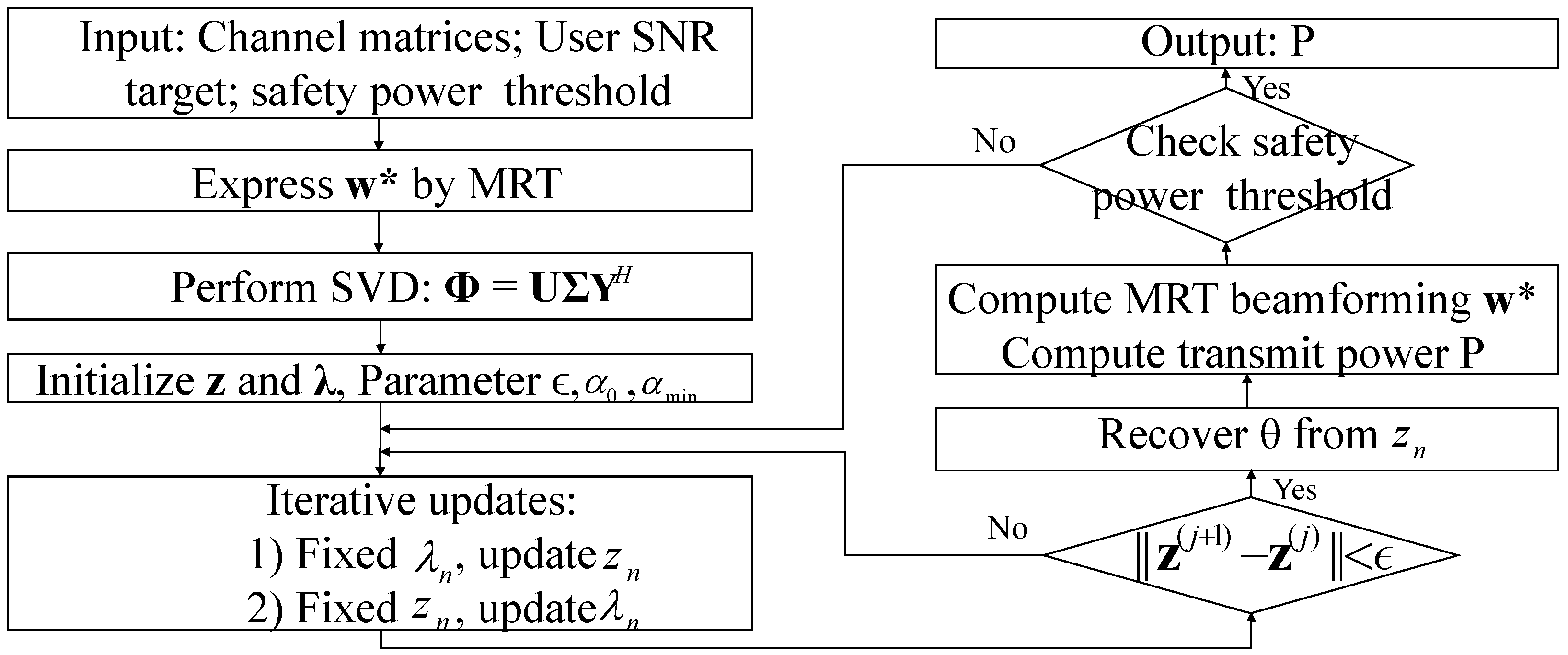
To verify whether the iterative solutions for z n and λ n satisfy the KKT conditions, two points need checking: the gradient of the Lagrangian function with respect to z n is zero, and λ n ( | z n | 2 1 ) = 0 . Firstly, since z n = e j ϕ n ensures | z n | 2 = 1 , λ n ( | z n | 2 1 ) = 0 . Secondly, since the expressions for z n and λ n are derived from L z * = 0 (the gradient of the Lagrangian function Equation (26) being zero), meeting the zero—gradient requirement. In summary, the expressions for z n and λ n satisfy KKT conditions, ensuring the optimality of solutions within the Lagrangian multiplier method framework. Finally, the optimal solutions for z n and λ n are obtained using an alternating iteration method. Algorithm 1 summarizes the optimization approach for solving (P4). To provide a more intuitive understanding of the overall procedure, a concise flow chart illustrating the main steps and their interactions is presented in Figure 3.
Algorithm 1 SVD-LOP Algorithm
1:
Initialize random phase shift vector z ( 0 ) with | z n ( 0 ) | = 1 .
2:
Set Lagrange multipliers λ ( 0 ) = 0 C N , and convergence threshold ϵ = 10 4 and step size α 0 = 0.1 , α m i n = 10 4 , and γ = 0.5 .
3:
repeat
4:
   For j = 1, 2, …, J m a x = 1000 ;
      Update α :
α j = max α 0 1 + j γ , α min ;
      Fix λ , Update z n :
     Update phases via (29);
      Fix z n , Update λ :
     To relaxed constraints, (28) gradient ascent update:
        λ n ( j + 1 ) = λ n ( j ) + α j z n ( j + 1 ) 2 1 ;
       j = j + 1 .
5:
until when z ( j + 1 ) z ( j ) < ϵ or max iterations reached.

3.2.2. Low-Complexity Successive Convex Approximation Algorithm

Due to SVD, the complexity of the SVD-LOP algorithm remains exponential [22]. To reduce the computational complexity, we propose the low-complexity successive convex approximation (LC-SCA) algorithm to obtain suboptional solutions for (P3). Specifically, (18) can convexly approximate by using the first-order Taylor expansion, followed by a series of transformations to implement iterations until meeting the convergence criteria. The detailed steps are as follows:
First, we expand (18), which is given by:
v H Φ Φ H v + v H Φ H M U + H M U H Φ H v + H M U 2 ,
Under the SCA approach, we perform a first-order Taylor expansion of the non-convex term v H Φ Φ H v at the current point v ( ) . This step converts the non-convex quadratic form into a linear term and form a convex approximate objective function based on the -th iteration point v ( ) , which is used to optimize and update the variable v in the ( + 1 ) -th iteration. After the first expansion, we can obtain expression
2 Re ( Φ Φ H v ( ) ) H v + 2 Re v H Φ H M U + H M U 2 v ( ) H Φ Φ H v ( ) .
By element-wise decomposition of the vector inner product in Equation (31) (while ignoring constant terms independent of v ), the multi-dimensional optimization (P3) is decomposed into the sum of multiple one-dimensional subproblems, formulated as
( P 5 ) : max v n n = 1 N 2 Re [ ( Φ Φ H v ( ) ) n + ( Φ H M U ) n ] v n * ,
s . t . | v n | = 1 , n { 1 , , N } .
Next, we introduce an update rule based on optimizing the angle θ n to achieve the suboptimal solution. This operation is essentially a polarization processing, and its core is to ensure that the variable v n always satisfies the constraint condition of | v n | = 1 during each iteration. The update rule is given as θ n + 1 = arg Φ Φ H v ( ) n + Φ H M U n . The updated iterative variable v n is
v n ( + 1 ) = e j   arg Φ Φ H v ( ) n + Φ H M U n .
Finally, we optimize the phase of a single IRS element while keeping the phase angles of all other elements fixed. Through continuous iterative optimization of the variables, it approaches the suboptimal solution of the (P5). To further analyze the proposed LC-SCA algorithm, its convergence can be established based on the standard theory of successive convex approximation (SCA) [20]. Specifically, convergence is guaranteed if the following three conditions are satisfied: (i) majorization, where the convex surrogate function constructed at the current iteration provides a global lower bound for the original non-convex objective; (ii) tangency, where the surrogate function coincides with the original objective in both value and first-order derivative at the current point; and (iii) continuity, where both the original objective and the surrogate function are continuous within the feasible region. Since the convex surrogate constructed in this work satisfies these conditions, the LC-SCA algorithm ensures monotonic improvement at each iteration and ultimately converges to a stationary point. This convergence property is consistent with prior studies [23]. Therefore, the LC-SCA algorithm is presented in detailed in Algorithm 2, highlighting the iterative updates of the IRS phase shifts and matrix operations. To more easily understand the workflow and convergence behavior of the LC-SCA algorithm, we provide a corresponding flowchart in Figure 4.
Algorithm 2 LC-SCA Algorithm
1:
Initialize the iteration = 0 , set the convergence threshold ϵ = 10 4 .
2:
Initialize the variable v ( 0 ) by the interior point method.
3:
repeat
4:
   For = 1, 2, …, L m a x = 1000 ;
5:
       For n = 1 , , N , update the n-th element and fix the rest of elements;
    a . Calculate the updated θ n + 1 = a r g ( ( Φ Φ H v ( ) ) n + ( Φ h M U ) n ) at the -th iteration;
    b . Obtain the updated variable v n ( + 1 ) = e j θ n + 1 ;
       Get v ( + 1 ) .
    =  + 1 .
6:
until  v ( + 1 ) v ( ) < ϵ or max iterations reached.

3.2.3. Complexity Analysis

The computational complexity of the SVD-LOP algorithm is determined for SVD and Lagrange multiplier iterative optimization. For the N × K channel matrix Φ , the SVD involves matrix multiplication and eigenvalue decomposition with a complexity of O ( N 3 ) , while the Lagrange iterative optimization has a complexity of O ( N 2 ) . Therefore, the overall per-iteration complexity of the SVD-LOP algorithm is the sum of these two components. In practical scenarios, an IRS typically has a large number of reflecting elements, i.e., N K , and the per-iteration complexity of the SVD-LOP algorithm can be approximated as O ( N 3 ) .
For the LC-SCA algorithm, the computational complexity is determined by matrix operations and IRS phase updates. Specifically, computing Φ Φ H v ( ) and Φ H M U incurs complexities of O ( N 2 K ) and O ( N K ) , respectively, while phase update has a complexity of O ( N 2 ) .The overall per-iteration complexity of the LC-SCA algorithm is O ( N 2 K ) , which can be given as O ( N 2 ) for N K .
For the SDR algorithm, its computational complexity is mainly determined by solving (P3) via semidefinite programming (SDP) [23]. Therefore, each iteration of the SDR algorithm requires a computational complexity as high as O ( N 7 ) . To provide a clearer comparison of the algorithm characteristics, we summarize the main features of the proposed SVD-LOP and LC-SCA algorithms, along with the SDR baseline, in Table 1.

4. Simulation Results

In this section, simulations are conducted to verify the effectiveness of the proposed 3D-TCGBSM system model and algorithms. A typical coal mine tunnel with 4 m in width and 5 m in height is considered. A coordinate system with MBS as the origin is established, where IRS is deployed at the top of this tunnel 50 m along the positive y-axis from MBS. Users move within the tunnel between MBS and IRS, and the horizontal distance from MBS to user is defined as d. In the coal mine communication system, each randomly moving cluster is set to contain 50 rays, and each channel-corresponding double cluster has an equal survival probability. According to the definition of the Markov birth/death process, the birth/death process is determined by the cluster generation rate and recombination rate ( λ G / λ R ) [19]. To characterize the channel response characteristics in underground mines, we set the frequency variable f to 915 MHz , which is a common commercial operating frequency in coal mine wireless communication systems [17]. In addition, the key parameters are shown in Table 2.
To verify the effectiveness of the proposed IRS-assisted 3D-TCGBSM model, we performed a sensitivity analysis of channel capacity under different tunnel roughness levels δ h . Three representative roughness values were considered: 0 (perfectly smooth tunnel), 0.02 (moderately rough), and 0.1 (very rough). Figure 5 illustrates the simulation results obtained from our proposed model across a range of SNR values. The results show that, as δ h increases, the overall channel capacity decreases due to stronger multipath scattering and attenuation; however, the IRS-assisted 3D-TCGBSM model consistently achieves higher capacity than the conventional GBSM reported in [24], particularly under high roughness conditions. For example, when δ h = 0.1 and SNR = 10 dB , the proposed model achieves a capacity of around 12 bit / s / Hz , which is significantly higher than the 7– 8 bit / s / Hz reported for the conventional GBSM in [25]. These results confirm that the proposed model not only preserves accurate characterization of the coal mine environment but also enhances channel capacity by leveraging IRS-assisted passive beamforming.
For the effectiveness of the proposed algorithms, we investigated the transmit powers at MBS under different schemes, as shown in Figure 6. The parameter settings are user SNR γ = 25 dB and the roughness of the mine tunnel δ h = 0.02 . It can be observed that for the scheme without IRS, the transmit power increases rapidly as the user moves away from the MBS, while for the IRS-assisted schemes, the transmit power first increases and then decreases as the user approaches the IRS. This demonstrates that deploying IRS can effectively reduce transmit power and expand signal coverage without installing additional active relays in the coal mine tunnels. However, the IRS random phase scheme shows almost no significant improvement compared to the proposed SVD-LOP, LC-SCA, and SDR algorithms, which highlights the necessity of IRS phase optimization. For these three algorithms, when d < 35 m , the transmit power of the proposed SVD-LOP and LC-SCA algorithms is lower than that of the SDR algorithm. This is because the probability that the SDR algorithm finds an QoS-satisfying vector via Gaussian randomization is significantly reduced in dynamically varying mine channel responses, whereas the SVD-LOP algorithm, based on channel matrix decomposition, offers better adaptability to real-time channel variations. When d > 35 m , the three algorithms exhibit nearly identical performance. Nevertheless, the computational complexity of the SDR algorithm is as high as O ( N 7 ) , while that of the proposed SVD-LOP and LC-SCA algorithms is O ( N 3 ) and O ( N 2 ) , respectively. Overall, these results indicate that the proposed algorithms can achieve comparable performance to SDR with significantly lower computational cost.
Building on this performance and complexity analysis, it is important to emphasize that, after IRS phase optimization, the required transmit power remains far below the explosion-proof power threshold of 6 W (i.e., 37.8 dBm ). As shown in Figure 6, the transmit power of the system without IRS approaches this threshold at around d = 50 m , posing a potential safety concern. In contrast, the proposed SVD-LOP and LC-SCA algorithms maintain a substantial safety margin even at 50 m . Specifically, the SVD-LOP algorithm achieves a transmit power of 8.9 dBm , representing a reduction of 28.9 dBm compared to the safety threshold, while the LC-SCA algorithm achieves 10.2 dBm , corresponding to a reduction of 27.6 dBm . This clearly demonstrates that the optimized IRS phase configuration keeps the transmit power well below the critical limit, thereby ensuring intrinsic safety in underground environments. Table 3 summarizes the transmit power (i.e., P m i n ) at distances d and their corresponding margins (i.e., Δ P ) relative to the 6 W explosion threshold. Therefore, the proposed algorithms achieve effective power optimization with low complexity, enhancing coverage and ensuring reliable coal mine communications.
Next, we investigate the impact of different roughness levels δ h of coal mine tunnels on the performance of the proposed SVD-LOP and LC-SCA algorithms and SDR algorithm, as shown in Figure 7. We set three typical roughness values: 0, 0.02 , and 0.1 . Simulation shows that as δ h increases, transmit power at MBS also increases, as expected. However, regardless of the roughness, the proposed SVD-LOP and LC-SCA algorithms consistently achieve lower transmit power than the SDR algorithm, which validates the effectiveness of the SVD-LOP and LC-SCA algorithms in coal mine scenarios.
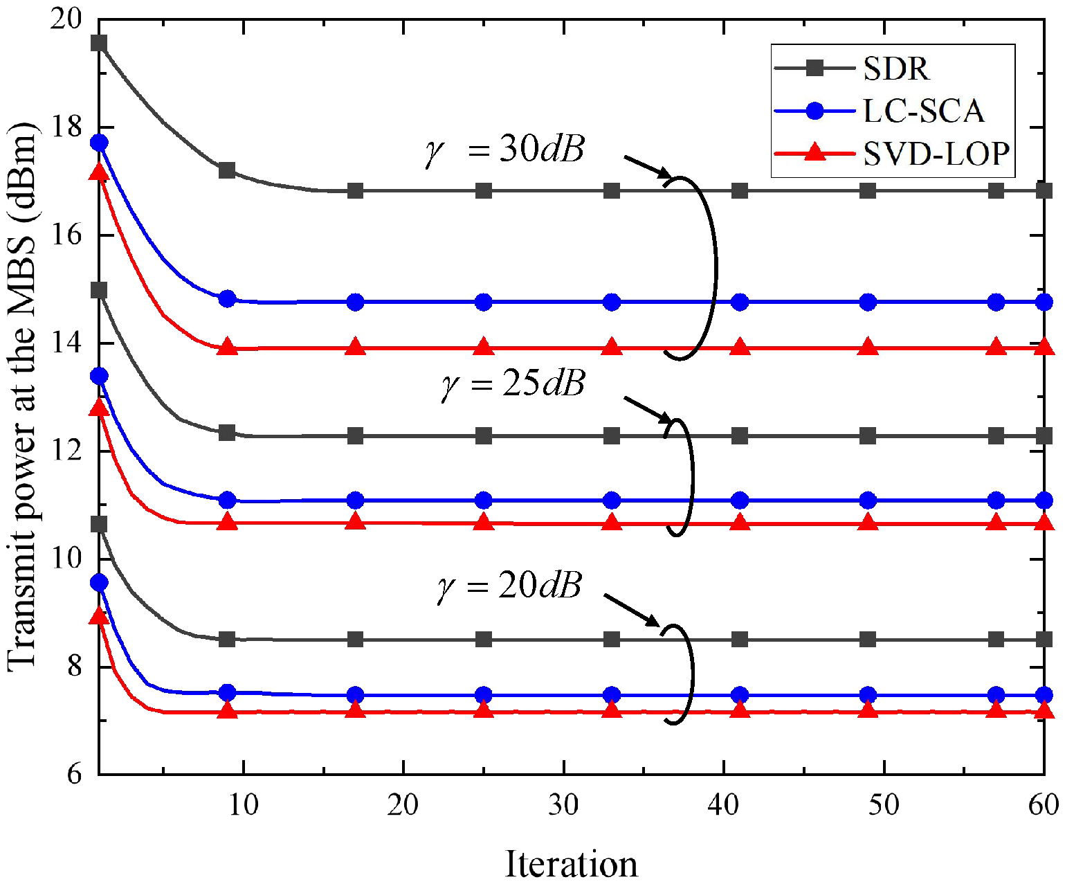
We validate the convergence of the proposed SVD-LOP and LC-SCA algorithms and SDR algorithm under different SNRs (i.e., 20 dB , 25 dB , and 30 dB ), as shown in Figure 8. Set δ h = 0.02 and d = 20 m . It can be seen that the convergence speed of the proposed SVD-LOP and LC-SCA algorithms is faster than that of the SDR algorithm at γ = 25 dB . In addition, for larger γ values, the performance improvement of the proposed SVD-LOP and LC-SCA algorithms increases compared to the SDR algorithm. Therefore, the SVD-LOP and LC-SCA algorithms exhibit better adaptability to the channel response in coal mine tunnel communication.
In the following, we compare the transmit power optimization of schemes with respect to the number of IRS reflecting elements at d = 20 m and d = 50 m , as shown in Figure 9. Set δ h = 0.02 and γ = 25 dB . At d = 20 m , it can be clearly observed that the proposed SVD-LOP and LC-SCA algorithms and SDR algorithm exhibit a clear trend of monotonically decreasing transmit power as the number of IRS reflecting elements increases. It is worth noting that the SDR algorithm exhibits the highest transmit power consumption among the three algorithms. Specifically, when d = 20 m and N = 64 , the transmit power of the SVD-LOP algorithm is 14.3 dBm , while the LC-SCA algorithm exhibits a transmit power of 15.4 dBm , and the SDR algorithm results in 17.9 dBm . When N = 100 , the SVD-LOP algorithm reduces its transmit power to 8.9 dBm , a decrease of 5.4 dBm compared to N = 64 ; the LC-SCA algorithm achieves 10.2 dBm , a reduction of 5.2 dBm ; the SDR algorithm’s transmit power decreases to 13.5 dBm , a reduction of 4.4 dBm . As the number of reflecting elements increases, the transmit power steadily decreases and eventually stabilizes, consistently remaining well below the explosion-proof safety threshold of 37.8 dBm . At d = 50 m , as the number of IRS reflecting elements increases, the performance of the SVD-LOP and SDR algorithms becomes nearly identical, while the performance gap between LC-SCA and the other two schemes continues to narrow, with all three algorithms showing significantly lower transmit power than the threshold. Although the SDR algorithm has a certain capability in optimizing transmit power, its computational complexity reaches O ( N 7 ) . In contrast, the proposed SVD-LOP and LC-SCA algorithms have significantly lower computational complexity, making them more suitable for dynamic and resource constrained environments such as coal mine communication.
We illustrate the relationship between achievable rate and the number of IRS reflecting elements under a fixed transmit power, as shown in Figure 10. Set γ = 25 dB and δ h = 0.02 , and fixed transmit power is 21 dBm , lower than the threshold. As expected, the achievable rate increases steadily with the number of IRS reflecting elements. It is obvious that the SVD-LOP algorithm consistently achieves the highest achievable rate, demonstrating its effectiveness in leveraging IRS phase-shift gains through channel matrix decomposition. The LC-SCA algorithm achieves comparable performance and closely follows SVD-LOP in most cases, which indicates its ability to maintain rate performance and significantly reduce computational complexity. In contrast, the SDR algorithm exhibits inferior performance. Simulation shows the proposed SVD-LOP and LC-SCA algorithms can optimize the achievable rate with low complexity, which makes them suitable for resource-limited environments such as coal mine communication.
In underground coal mine wireless communication scenarios, system performance is affected by several non-ideal factors, including IRS phase noise induced by hardware imperfections, phase quantization errors caused by discrete phase shifters, and the time-varying characteristics of the channel due to dynamic scatterers such as moving coal dust. To evaluate the robustness of the proposed algorithms under these practical impairments, we conducted additional simulations and analyses. First, in the presence of phase noise [24], the IRS reflection matrix can be modeled as
Q = β n diag ( e j θ 1 + θ σ , , e j θ N + θ σ )
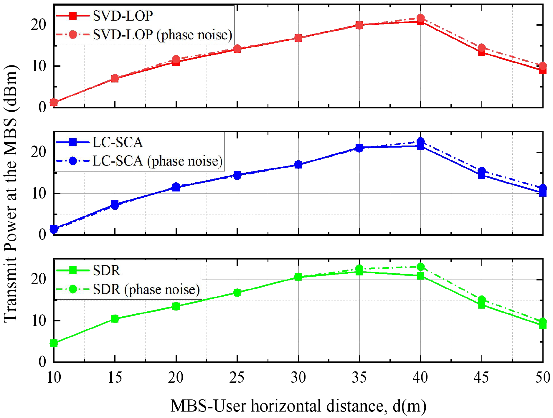
where β n denotes the amplitude coefficient ( β n = 1 ) ans θ σ the phase noise following the distribution of N ( 0 , σ σ 2 ) . After introducing the same phase noise σ σ 2 = 1 , we compare the performance of the proposed SVD-LOP and LC-SCA algorithms with the SDR algorithm, as shown in Figure 11. It indicates that the MBS transmit power slightly increases under the same phase noise condition. However, both the proposed SVD-LOP and LC-SCA algorithms consistently outperform the SDR algorithm in the presence of identical phase noise. The peak transmit power under phase noise is 21.7 dBm for SVD-LOP, 22.6 dBm for LC-SCA, and 23.09 dBm for SDR. These results clearly demonstrate that, compared with the benchmark algorithm, the proposed methods exhibit superior robustness in the presence of phase noise and remain well below the explosion-proof safety threshold.
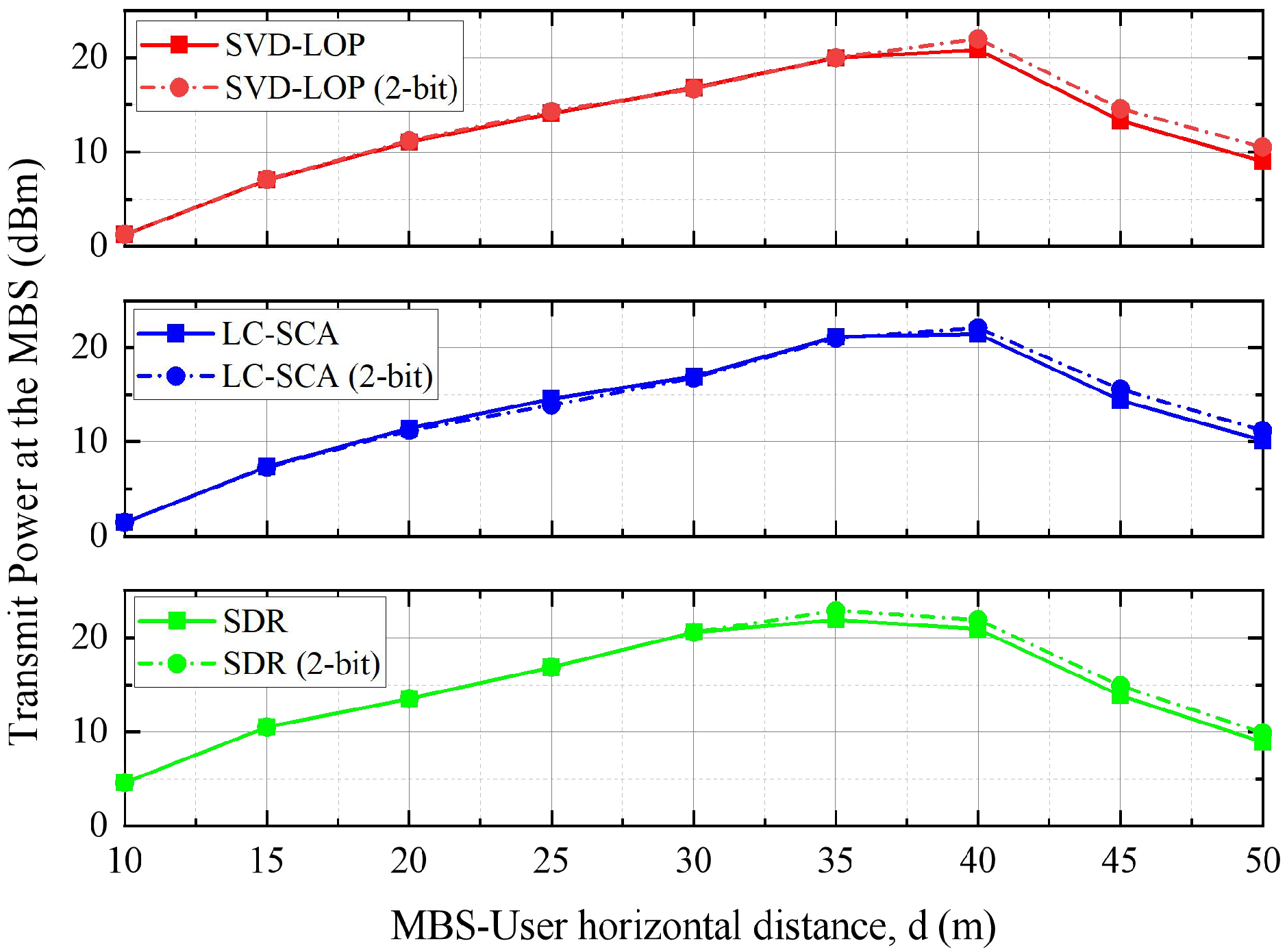
Then, with regard to the IRS phase quantization described in [11,26,27,28], we consider practical discrete phase shifts, that is, θ { 0 , 2 π / μ , , ( μ 1 ) 2 π / μ } , where μ = 2 b is the number of quantized levels when b-bit quantization is used. Specifically, we choose 2-bit quantization and randomly generate θ { 0 , 2 π / μ , , ( μ 1 ) 2 π / μ } , as shown in Figure 12. It can be observed that the minimization transmit power will increase slightly, but under the same quantization error, the proposed SVD-LOP and LC-SCA algorithms always outperform the SDR algorithm. The simulation results show, to some extent, that the proposed SVD-LOP and LC-SCA algorithms have better robustness.
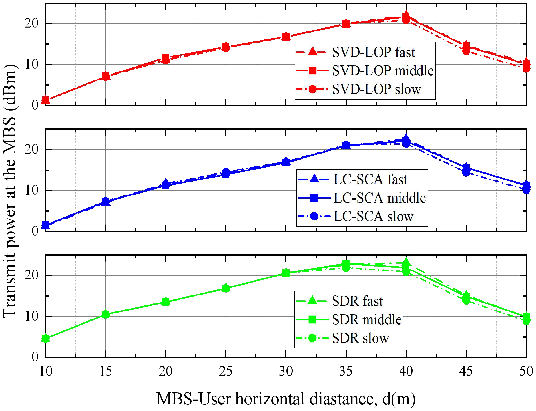
Finally, the 3D-TCGBSM model in our channel modeling characterizes temporal variations based on the generation and disappearance of clusters (Markov birth–death process) combined with tunnel structural features and environmental factors such as scattering surface roughness [19]. This framework captures the random appearance and disappearance of scattering clusters caused by coal dust in coal mine tunnels, which leads to fluctuations in the equivalent channel gain and phase over time. By explicitly introducing parameters such as the cluster generation rate λ G and recombination rate λ R into the channel modeling, we are able to directly represent time-varying processes with different speeds. Specifically, we considered three representative scenarios: “slow” ( λ G = 5 , λ R = 1 ), “medium” ( λ G = 20 , λ R = 1 ), and “fast” ( λ G = 50 , λ R = 1 ), corresponding to channels with slow, moderate, and fast cluster dynamics, respectively, as shown in Figure 13. The simulation results demonstrate that under all three cluster variation rates, the proposed SVD-LOP and LC-SCA algorithms consistently maintain significant power optimization advantages.
In summary, the supplementary simulations considering IRS phase noise, quantization errors, and time-varying channels demonstrate that the proposed SVD-LOP and LC-SCA algorithms maintain stable power optimization performance under practical non-ideal conditions, with the transmit power consistently remaining well below the explosion-proof threshold in coal mines. Compared with the SDR algorithm, the proposed methods exhibit stronger robustness to these impairments, providing a solid foundation for their practical deployment in complex underground coal mine wireless communication systems.
5. Conclusions

This paper mainly addressed the MiniPower problem for IRS-assisted wireless communications in underground coal mine scenarios. We first developed a 3D-TCGBSM channel model to accurately characterize the harsh propagation environment. Then we proposed the SVD-LOP algorithm and the lower-complexity LC-SCA algorithm to solve the non-convex MiniPower optimization problem. Simulation results indicated that both proposed algorithms achieved significant power reduction compared to the conventional SDR algorithm before peak power and offered substantially lower computational complexity, which also exhibits robust performance across varying tunnel roughness conditions and user SNR targets. Our work demonstrated the potential of IRS passive beamforming to enhance power efficiency and reduce explosion risks in coal mine environments while maintaining reliable communication, which provides a feasible solution to design low power consumption IoT devices deployed in the coal mine. In the future, we will extend our work to the design of integrated sensing and communication in the coal mine IoT scenario for safe monitoring and production.

Author Contributions

Conceptualization, Y.L. and Y.X.; Methodology, Y.L.; Validation, X.L.; Formal analysis, X.L.; Writing—original draft, X.L.; Writing—review and editing, Y.L., X.L. and Y.X.; Funding acquisition, B.W. All authors have read and agreed to the published version of the manuscript.

Funding

This research was funded by the National Natural Science Foundation of China, grant numbers 62271386, 62471385, and 61801371.

Data Availability Statement

Data are contained within the article.

Conflicts of Interest

The authors declare no conflict of interest.

References

  1. Li, C. Research status and development direction of 5G key technologies for coal mines. J. Mine Autom. 2024, 50, 79–88. [Google Scholar]
  2. Sun, J. Research and development of 5G communication system standards for coal mines. J. Mine Autom. 2023, 49, 1–8. [Google Scholar]
  3. Xin, L.; Yuan, F.; Chenxin, L. Research on the application of 5G characteristics in intelligent mine. J. Mine Autom. 2022, 48, 136–141. [Google Scholar]
  4. Bengtsson, M.; Ottersten, B. Optimal and Suboptimal Transmit Beamforming, Handbook of Antennas in Wireless Communications, 1st ed.; CRC Press: Boca Raton, FL, USA, 2001; pp. 582–606. [Google Scholar]
  5. Li, S.; Yang, R.; Yang, L.; Shen, S.; Li, F.; Hu, Q. Survey of the non-line-of sight wireless coverage technology by reconfigurable intelligent surfaces in underground coal mines. J. China Univ. Min. Technol. 2024, 53, 613–622. [Google Scholar]
  6. Gong, S.; Lu, X.; Hoang, D.T.; Niyato, D.; Shu, L.; Kim, D.I.; Liang, Y.C. Toward smart wireless communications via intelligent reflecting surfaces: A contemporary survey. IEEE Commun. Surv. Tutorials 2020, 22, 2283–2314. [Google Scholar] [CrossRef]
  7. Yuan, X.; Zhang, Y.-J.A.; Shi, Y.; Yan, W.; Liu, H. Reconfigurable-Intelligent-Surface Empowered Wireless Communications: Challenges and Opportunities. IEEE Wirel. Commun. 2021, 28, 136–143. [Google Scholar] [CrossRef]
  8. Wu, Q.; Zhang, R. Intelligent reflecting surface enhanced wireless network via joint active and passive beamforming. IEEE Trans. Wirel. Commun. 2019, 18, 5394–5409. [Google Scholar] [CrossRef]
  9. Tang, J.; Peng, Z.; So, D.K.; Zhang, X.; Wong, K.K.; Chambers, J.A. Energy Efficiency Optimization for a Multiuser IRS-Aided MISO System With SWIPT. IEEE Trans. Commun. 2023, 71, 5950–5962. [Google Scholar] [CrossRef]
  10. Almekhlafi, M.; Arfaoui, M.A.; Assi, C.; Ghrayeb, A. A low complexity passive beamforming design for reconfigurable intelligent surface (RIS) in 6G networks. IEEE Trans. Veh. Technol. 2023, 72, 6309–6321. [Google Scholar] [CrossRef]
  11. Wu, J.; Shim, B. Power minimization of intelligent reflecting surface-aided uplink iot networks. In Proceedings of the 2021 IEEE Wireless Communications and Networking Conference (WCNC), Nanjing, China, 29 March–1 April 2021; pp. 1–6. [Google Scholar]
  12. Han, H.; Zhao, J.; Zhai, W.; Xiong, Z.; Niyato, D.; Di Renzo, M.; Pham, Q.V.; Lu, W.; Lam, K.Y. Reconfigurable Intelligent Surface Aided Power Control for Physical-Layer Broadcasting. IEEE Trans. Commun. 2021, 69, 7821–7836. [Google Scholar] [CrossRef]
  13. Liu, Y.; Zhao, J.; Li, M.; Wu, Q. Intelligent reflecting surface aided MISO uplink communication network: Feasibility and power minimization for perfect and imperfect CSI. IEEE Trans. Commun. 2020, 69, 1975–1989. [Google Scholar] [CrossRef]
  14. Wu, Q.; Zhang, R. Joint active and passive beamforming optimization for intelligent reflecting surface assisted SWIPT under QoS constraints. IEEE J. Sel. Areas Commun. 2020, 38, 1735–1748. [Google Scholar] [CrossRef]
  15. Liu, R.; Li, M.; Liu, Q.; Swindlehurst, A.L. Joint symbol-level precoding and reflecting designs for IRS-enhanced MU-MISO systems. IEEE Trans. Wirel. Commun. 2020, 20, 798–811. [Google Scholar] [CrossRef]
  16. Guo, T.; Wang, Y.; Xu, L.; Mei, M.; Shi, J.; Dong, L.; Xu, Y.; Huang, C. Joint communication and sensing design for multihop RIS-aided communication systems in underground coal mines. IEEE Internet Things J. 2023, 10, 19533–19544. [Google Scholar] [CrossRef]
  17. Liu, Y.; Yang, Z.; Wang, B.; Xu, Y. Rate Optimization of Intelligent Reflecting Surface-Assisted Coal Mine Wireless Communication Systems. Entropy 2024, 26, 880. [Google Scholar] [CrossRef]
  18. Guo, T.; Li, X.; Mei, M.; Yang, Z.; Shi, J.; Wong, K.K.; Zhang, Z. Joint communication and sensing design in coal mine safety monitoring: 3-D phase beamforming for ris-assisted wireless networks. IEEE Internet Things J. 2023, 10, 11306–11315. [Google Scholar] [CrossRef]
  19. Chang, H.; Wang, C.X.; Liu, Y.; Huang, J.; Sun, J.; Zhang, W.; Bai, Z.; An, K.; Li, Z.; Aggoune, E.H.M. A general 3-D nonstationary GBSM for underground vehicular channels. IEEE Trans. Antennas Propag. 2022, 71, 1804–1819. [Google Scholar] [CrossRef]
  20. Tang, R.; Zhou, X. Singular value decomposition channel estimation in STBC MIMO-OFDM system. Appl. Sci. 2019, 9, 3067. [Google Scholar] [CrossRef]
  21. Shi, Q.; Hong, M. Penalty dual decomposition method for nonsmooth nonconvex optimization—Part I: Algorithms and convergence analysis. IEEE Trans. Signal Process. 2020, 68, 4108–4122. [Google Scholar] [CrossRef]
  22. Kettlun, F.; Rosas, F.; Oberli, C. A low-complexity channel training method for efficient SVD beamforming over MIMO channels. EURASIP J. Wirel. Commun. Netw. 2021, 2021, 151. [Google Scholar] [CrossRef]
  23. Kumar, V.; Zhang, R.; Renzo, M.D.; Tran, L.-N. A Novel SCA-Based Method for Beamforming Optimization in IRS/RIS-Assisted MU-MISO Downlink. IEEE Wirel. Commun. Lett. 2023, 12, 297–301. [Google Scholar] [CrossRef]
  24. Li, C.; van Delden, M.; Sezgin, A.; Han, Z. IRS-Assisted MISO System With Phase Noise: Channel Estimation and Power Scaling Laws. IEEE Trans. Wirel. Commun. 2023, 22, 3927–3941. [Google Scholar] [CrossRef]
  25. Ji, X.; Wang, C.X.; Chang, H. A Novel MIMO Channel Model for Underground Mine Communications. In Proceedings of the IEEE/CIC International Conference on Communications in China (ICCC), Dalian, China, 10–12 August 2023; pp. 1–5. [Google Scholar]
  26. Verma, R.; Kumar, P.; Sharma, P.K. Average BER of RIS-Assisted NOMA System with Quantized Phase Error Under Nakagami-M Fading. In Proceedings of the National Conference on Communications (NCC), New Delhi, India, 6–9 March 2025; pp. 1–6. [Google Scholar]
  27. Wang, B.; Yuan, Z.; Lu, J.; Zhang, X. Multitask Collaborative Learning Neural Network for Radio Signal Classification. IEEE Trans. Commun. 2025, 73, 2480–2489. [Google Scholar] [CrossRef]
  28. Wang, B.; Yuan, Z.; Lu, J.; Zhang, X. Mixed Data Augmentation Through the Integration of Mode Decomposition and Time-Series Transformation for Radio Signal Classification. IEEE Trans. Cogn. Commun. Netw. 2025, 1, 1. [Google Scholar] [CrossRef]
Figure 1. IRS-assisted 3D-TCGBSM coal mine wireless communication system model.
Iot 06 00059 g001
Figure 2. Geometry of IRS-assisted 3D-TCGBSM coal mine wireless communication system model.
Iot 06 00059 g002
Figure 3. Flowchart for SVD-LOP algorithm.
Iot 06 00059 g003
Figure 4. Flowchart for LC-SCA algorithm.
Iot 06 00059 g004
Figure 5. Effect of surface on channel capacity for 3D-TCGBSM model.
Iot 06 00059 g005
Figure 6. MBS transmit power versus MBS–user horizontal distance.
Iot 06 00059 g006
Figure 7. Effect of surface roughness on transmit power at the MBS.
Iot 06 00059 g007
Figure 8. Convergence analysis of the proposed algorithms and SDR algorithm.
Iot 06 00059 g008
Figure 9. Transmit power vs. number of IRS reflecting elements. (a) d = 20 m ; (b) d = 50 m .
Iot 06 00059 g009
Figure 10. Achievable rate vs. number of IRS reflecting elements.
Iot 06 00059 g010
Figure 11. MBS transmit power versus MBS–user horizontal distance under the same phase noise.
Iot 06 00059 g011
Figure 12. MBS transmit power versus MBS–user horizontal distance under the same quantization errors.
Iot 06 00059 g012
Figure 13. MBS transmit power versus MBS–user horizontal distance under the cluster variation rates.
Iot 06 00059 g013
Table 1. Characteristic comparison of algorithms.
AlgorithmSVD/Matrix Calculation ComplexityLagrange Iterative/IRS Phase Updates ComplexityPer-IterationIterationTotal Complexity
SVD-LOP O ( N 3 ) O ( N 2 ) O ( N 3 ) J O ( J N 2 )
LC-SCA O ( N 2 K ) + O ( N K ) O ( N 2 ) O ( N 2 ) L O ( L N 2 )
SDR baseline-- O ( N 7 ) I O ( I N 7 )
Table 2. Main parameters for simulations.
System ParametersValue
Number of IRS reflecting elements, N 10 × 10
Monte Carlo trials of all algorithms, M C 200
Random seeds of all algorithms, R S 2025
Noise standard deviation, σ −80 dBm
Number of MBS antennas, K4
Birth control parameter, λ G 20
Death control parameter, λ R 1
Normalized path loss, C 0 −30 dB
Frequency variable, f915 MHz
Carrier frequency, f c 2.45 GHz
Tunnel roughness, δ h 0.02
Table 3. Comparison of transmit power and difference from power threshold under different schemes.
d/(m)Without IRS/(dBm)SVD-LOP/(dBm)LC-SCA/(dBm)SDR/(dBm)
P min Δ P P min Δ P P min Δ P P min Δ P
2014.423.411.126.711.526.313.524.3
2517.720.114.123.714.523.316.821.0
3020.417.416.821.016.920.920.517.3
3522.715.119.917.921.116.721.816.0
4024.713.120.817.021.416.420.817.0
4526.711.113.324.514.423.413.824.0
5029.38.58.928.910.227.68.928.9
Disclaimer/Publisher’s Note: The statements, opinions and data contained in all publications are solely those of the individual author(s) and contributor(s) and not of MDPI and/or the editor(s). MDPI and/or the editor(s) disclaim responsibility for any injury to people or property resulting from any ideas, methods, instructions or products referred to in the content.