1. Introduction
The recent enhancements in Information and Communication Technology (ICT), such as IoT, Cloud computing, Fog computing, and Machine Learning, have significantly impacted the reshaping of livestock farming [
1], paved the way for precision agricultural practices, and improved efficiency in livestock management. These advancements have led to increased productivity, reduced waste, and improved animal welfare.
Applications that monitor and control animals’ welfare and accurately detect reproductive cycles for increased production and reproduction are no longer futuristic; they are now achievable with ICT innovations. Various Cloud-based IoT farming techniques involve collecting data using sensors and sending it to the Cloud for analysis and processing. Then, based on the results, instructions are sent to the actuators to complete specific tasks [
2,
3]. In these systems, the powerful computing capability of the Cloud unit can always easily meet the processing requirements of the system. In addition, a notable issue is that Cloud units are typically geographically distant from the data collection devices. Large volumes of data travel a long distance to the Cloud after being collected on the site. This creates an enormous bandwidth utilization and some security risks when raw data travel on the Internet. The negative effects of the high latency and energy consumption also need to be considered.
With the rise of Fog computing, first developed by CISCO in 2012 [
4], new Fog–Cloud-based applications provide computational processing closer to the data collection devices. These systems are more secure as the raw data no longer need to be sent to the Cloud directly, and more importantly, the communication latency is reduced. A lower communication cost is observed as more data are processed locally.
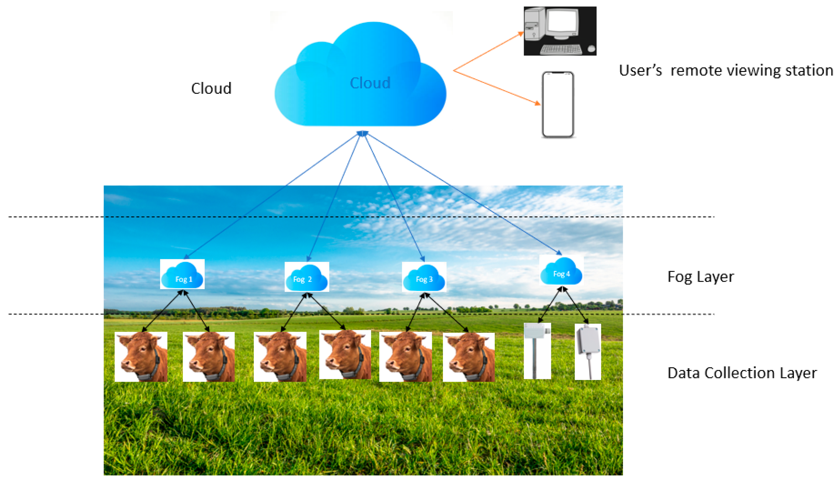
Livestock farms are usually located far from urban areas, with communication issues of power consumption, latency sensitivity, limited bandwidth, etc. This paper, therefore, proposes a Fog–Cloud-based IoT network architecture to satisfy the requirements of an IoT livestock farming system. In this architecture, data collected from the sensors mounted on animals are processed on the Fog device, and only the results are sent to the Cloud for storage and remote viewing. Based on the results of the processing performed in the Fog device, actions are triggered on the actuators to complete specific tasks. Reduced communication latency occurs as data are processed closer to the data collection devices and actuators. The overall system efficiency and response time are greatly improved, leading to faster and more efficient operations.
The system is simulated and evaluated using iFogSim, a novel Java-based Fog–Cloud simulator that models Fog–Cloud-based IoT environments and measures their parameters, simulating the interactions between Fog, Cloud, and sensor technologies. This novel simulation tool is not yet widely used in such applications, but it has the potential to have more contributions to research in IoT-based livestock farming systems.
The simulation results validate the proposed method’s main advantages over Cloud-based IoT systems, particularly in reduced latency and energy consumption. This study shows two times higher power consumption and five to ten times higher latency in the Cloud-based system compared to the proposed Fog–Cloud-based system depending on the number of sensors used in the simulation. Therefore, the proposed Fog–Cloud-based system offers significant efficiency improvements compared to the traditional Cloud-based IoT systems.
This paper is structured as follows: Related works are presented in
Section 2, the proposed system’s components are outlined in
Section 3, the methodology is shown in
Section 4, and the simulation and results are depicted in
Section 5.
2. Related Works
Various systems have been developed over the years for smart farming. Many of them are based on Cloud-based architecture, but more recently, a Fog–Cloud-based architecture has attracted attention in the agricultural field. In particular, in intelligent livestock management systems, these systems gathered data and processed them via a Fog–Cloud-based system [
5], including body temperature, heartbeat rate, location, movement (lying down, standing, or sleeping), and environmental data such as temperature and humidity. Using technology to gather information on animal health, behavior, and productivity is a key aspect of data collection in smart livestock farming systems. To increase productivity and animal welfare, farmers can use technology to track their livestock in real time and make well-informed decisions. This innovative approach to data collection is revolutionizing the way livestock farming is managed and has the potential to greatly benefit both farmers and animals [
6,
7]. Additionally, the data collected can be analyzed to identify patterns and trends that can help farmers improve their processes. By using this technology, farmers can also detect early signs of illness or distress in their animals, leading to better care and potentially higher yields. This can ultimately result in improved animal welfare and overall farm efficiency [
7].
Data collection devices in smart livestock farming systems perform various tasks, including animal identification via RFID tags, delivering advisories through teleservices and SMS, facilitating connections among farmers through social media and mobile telephony, and employing sensor-based systems for monitoring. Furthermore, artificial intelligence technologies such as Machine Learning, Cloud computing, and the Internet of Things are used to change the livestock business into a more efficient and data-driven industry [
8]. This technological integration allows for improved monitoring of livestock health and behavior, ultimately leading to better decision-making processes within the industry. As a result, farmers and ranchers can optimize their operations and maximize productivity. In smart livestock farming, accelerometers are used to measure animal movement and activity levels, heart rate sensors are used to track cardiovascular function and stress levels, and GPS is used to study cattle grazing behavior and energy expenditure [
7]. Accelerometers have been used in [
9] to measure the walking, resting, and eating behaviors of animals as well as to calculate energy expenditure. They have also been attached to animals’ legs, necks, ears, or tails to track movement trajectories. Leg-mounted accelerometers are commonly used in dairy cows to measure lying time and walking behavior. Accelerometers can help monitor animal activity and behavior in real time. In [
10], GPS was used for animal tracking to determine the location and movement patterns. The system integrates GNSS technology with cellular communication to provide accurate and continuous monitoring of animal behavior and movement. These data can then be analyzed to better understand animal habits and interactions. Other sensors, such as heart rate monitors and temperature monitors, were used in [
11,
12] to provide a more comprehensive understanding of the animals’ well-being in addition to the behavioral data. In [
8], cameras were used to monitor and count livestock animals like pigs. The system involves fitting animals with Bluetooth Low Energy tags and using wireless broadband antennas to track their movements. Additionally, image processing and deep learning methods are employed to identify animals based on camera data. The data collected are then analyzed to provide insights into animal health, behavior, and overall well-being.
Livestock smart farming relies on effective communication protocols to facilitate data exchange and monitoring within the system. These protocols help ensure a seamless integration of various sensors, devices, and systems to manage livestock health and productivity. Understanding the communication protocols used in livestock smart farming is crucial for optimizing efficiency and ensuring the well-being of the animals. A variety of protocols have been used in livestock smart farming, including LoRaWAN, Zigbee, and NB-IoT. Each protocol has its unique advantages and disadvantages; so, it is important to carefully evaluate which one is best suited for a specific farm’s needs. For instance, several studies have applied GNSS technology combined with LPWAN to send GPS coordinates over networks like LoRaWAN, NB-IoT, and Sigfox. Livestock theft management is another use case for livestock location monitoring, with systems using technologies like RFID and GPRS for tagging and identification [
10]. GPS coordinates can be tracked in real time to prevent theft and ensure the safety of livestock. LoRaWAN enhances livestock monitoring by offering a beneficial and adaptable solution for real-time comprehensive tracking and oversight while ensuring regulatory compliance. It provides both online and offline monitoring; adaptive dual radio (FSK and LoRaWAN) for optimizing energy, bandwidth, and range; adaptive movement data streaming modes utilizing a vector quantization compression technique; and extended battery longevity [
10,
13]. The system is designed to improve efficiency and accuracy in livestock management. On the reverse side, Zigbee is used for short-range and low-power wireless communication in livestock monitoring systems. Additionally, Zigbee technology allows for easy scalability and integration with other devices, but it may not be suitable for larger outdoor areas with extensive range requirements. However, Zigbee can still be a useful tool for smaller-scale livestock operations. Similarly to Zigbee, Bluetooth Low Energy (BLE) is a short-range and low-cost wireless technology that is used in indoor smart farming applications for monitoring livestock and poultry feeding environments. BLE has lower costs and power consumption compared to traditional Bluetooth, making it suitable for scenarios requiring high real-time transmission. Additionally, Bluetooth Low Energy (BLE) technology is utilized for short-range communication between devices [
14,
15,
16]. GNSS technology has been integrated with cellular communication for monitoring livestock location, with GPS technology widely used for accurate location estimations.
Cloud computing and Fog computing have significantly changed how smart livestock farming systems work, enabling real-time data gathering, analysis, and decision-making. By utilizing Cloud and Fog computing technologies, farmers are able to monitor and manage their livestock more efficiently and effectively. Integrating Cloud and Fog computing in smart farming systems has the potential to significantly enhance productivity and sustainability in the agricultural industry. Raspberry Pi was utilized as a Fog device for initial data analysis, with the results being transmitted to the Cloud supported by Amazon Web Services (AWS) [
17]. A system leveraging Cloud technology, incorporating the ESP2866 Wi-Fi module and HC-05 Bluetooth module, was implemented in [
11] for the purposes of data collection and communication. A livestock tracking system was established [
5], enabling the use of a Wireless Power Transmitter (WPT) to transmit Radio Frequency signals (RF) via a Wireless Sensor Node (WSN) attached to the livestock, enhancing monitoring capabilities. Furthermore, a range of smart devices and schemes were innovated, such as advanced smart sensors, to further enhance the capabilities of smart livestock farming systems [
18,
19].
The system described in reference [
20,
21] was simulated using iFogsim. It utilized an IPex16 CPS to connect sensors and transmit the collected data to the Cloud via an ordinary computer. However, the systems mentioned above were designed with a focus on crop farming, not livestock farming. In those systems, sensor-collected data undergo initial processing in the Fog for latency-sensitive tasks before being transmitted to the Cloud for further processing.
For instance, other related works, such as [
1], delved into the software aspect of the system. In livestock farming [
22], Machine Learning algorithms like support vector machines and k-nearest neighbors are commonly employed. Computer vision and deep learning techniques were specifically used in [
23] to identify undergrown pigs in a group-housed pig room. Data were captured using a top-mounted camera and transmitted to the Cloud via radio links for analysis by employing deep learning techniques.
As
Table 1 demonstrate, the majority of studies and research concentrate on various data collection methods, including sensor-based data collection, and Machine Learning algorithms for disease prevention and crop development. Based on the current literature, a limited number of studies, such as [
21], have addressed the significance of latency and reduced power consumption in smart livestock systems. The strategy involves bringing the Cloud device closer to the data source with the use of Fog devices. A similar architecture was proposed in healthcare monitoring [
24,
25,
26], demonstrating 36% and 52% total power reduction when processing at the Fog compared to traditional Cloud-based systems, leading to improved efficiency in patient data management. Furthermore, in the domain of traffic management [
25], research has shown a 40.88% enhancement in task execution efficiency and a 66.39% reduction in power consumption within the Fog infrastructure, showcasing the applicability of these advancements in optimizing traffic control systems.
This paper introduces a network architecture for smart livestock systems that includes both Fog and Cloud layers. The Fog layer aims to reduce power consumption by processing the data closer to the source, minimize latency through a distributed processing approach, and improve response time by leveraging edge computing capacities, contrasting the higher latency in Cloud-based systems attributed to the distance from data collection devices to the Cloud server. Within the proposed architecture, positioning data collection devices in proximity to the processing layer offers advantages such as faster data processing and reduced latency, enhancing the overall efficiency of the system. Incorporating a Fog layer in the proposed architecture facilitates local processing, enabling immediate responses for applications such as livestock tracking without necessitating data transmission to the Cloud server, thereby enhancing system responsiveness and data privacy.
4. Results
The simulation was conducted using iFogsim. The simulator is used to evaluate resource utilization, such as the bandwidth utilized, the energy utilized by the devices, the latency of the system, and the computation cost [
26]. This study proposes two simulation scenarios: a Cloud-based scenario and a Fog–Cloud-based scenario. The two scenarios are then compared regarding power consumption and the system’s latency.
In both scenarios, the devices are configured as shown in
Table 2.
In both simulation scenarios, we used LoRaWAN’s characteristics for network communication. LoRaWAN is a Low-Power Wide-Area Network (LPWAN) protocol that uses LoRa (long-range) physical radio communication techniques. Its data transmission ranges between 300 bps and 50,000 bps depending on factors such as poor weather conditions, signal interference, and the distance between the sensors and the gateway. LoRaWan is also a great network communication solution for livestock monitoring systems in remote farms as its low power consumption and long range of data transmission are ideal for the remote framing setup.
The simulation uses 1000 bps of symmetrical (uplink and downlink) data transmission rates for both the Cloud-based and the Fog–Cloud-based models. However, the propagation delay—the amount of time it takes for a signal to go from one place to another—is higher in the Cloud-based model because of the greater distance between the sensors and the ISP router. We consider in this simulated model that the closest animal is 1000 m (one thousand meters) away from the ISP router. The propagation delay is calculated as follows.
The simulation also uses 1000 bps of symmetric bandwidth for the Fog–Cloud-based system. Due to the shorter distance between the Fog devices and the sensors, the propagation delay is smaller. In this design, the processing of sensed data is performed in the Fog layer and only the result is sent to the Cloud.
Additionally, more RAM (64 GB) and computing power are allocated to the Cloud-based simulation scenario because of the massive computing power of the Cloud unit.
We measured the system operation’s delay and energy consumption in both systems (Cloud-based and Fog–Cloud-based). To achieve this, five different setups were built for both scenarios with sensors ranging from 1 to 32.
In the Cloud-based design, the sensors collect data and send them directly to the Cloud through an access point (ISP router). In this method, the processing of sensed data is performed in the Cloud.
Figure 4 illustrates how devices are connected in a Cloud-based system in the simulator.
In a real-world farm layout, the ISP router is situated in a farmhouse that is kilometers away from the animal pasture. This is caused by certain networks and, occasionally, electrical limitations. Sensed data are gathered using sensors that are attached to the animal and strategically placed across the pasture. The sensed data will then travel from the sensors to the ISP router and, from there, will be routed to the Cloud.
In the simulated setup, the sensed data travel from the sensors, where they are generated, through the switches (ISP) to the Cloud, where the processing is performed. Then, the resulting action tuple is generated and travels back through the same switches to the actuator to execute the task. The symmetric propagation delay in this scenario is 2 s due to the delay between the sensors and the ISP router. In a real-life setup over a LoRaWAN infrastructure, this delay typically ranges from 0.1 to 0.5 milliseconds. It depends on the physical distance between the sensors and the ISP router, as well as the delay between the ISP router and the Cloud, which commonly ranges between 500 milliseconds to 2 s or more. This depends on the type of infrastructure in use (e.g., fiber, satellite, or cellular) and the distance between the ISP router and the Cloud. For instance, if the Cloud is hosted in New York City (USA) and the farm is located in a small village in Mpumalanga (South Africa), the data must travel through multiple routers and switches to reach the Cloud and return. Other environmental factors, such as trees and terrain in the pasture, also affect the propagation delay. This scenario also assumes that the communication protocol used is LoRaWAN.
In the Fog–Cloud-based system, as shown in
Figure 5, data collected from the sensors are processed locally in the Fog nodes and the action is sent to the actuator from the Fog layer. Then, the result is sent to the Cloud for remote viewing or access.
In a real-world setup, the Fog devices will be placed at strategic locations in the animal’s pasture, thus reducing the distance between the sensed data and the processing unit.
The propagation delay in this scenario is 0.1 s (s) due to the shorter distance between the sensors and the Fog nodes. Data travel from the sensors, where they are generated, to the Fog nodes, where they are processed. Then, the resulting action is generated in the Fog layer and sent to the actuator for the execution of the task. In this scenario, only the final result is sent to the Cloud to enable the system’s user to view it from a remote location. Both scenarios (Cloud-based and Fog–Cloud-based) defined above were simulated using iFogsim.
Table 3 shows the results from the simulation performed. In the simulation, one finds the differences in energy consumption and the overall delay of the system. However, it is also worth noting that the processing delay for the execution of each tuple (task sequence of the application) remains the same in the Cloud-based system and the Fog–Cloud-based system. This is because, since the task’s execution delay is not part of this study, the assumption is that the Cloud’s and the Fog’s execution time of each tuple will be the same.
In
Figure 6, we compared the overall delays of the proposed system and the Cloud-based system. We conducted the simulation using six different scenarios with 1, 2, 4, 8, 16, and 32 sensors. The simulation results showed that the proposed method outperformed the Cloud-based system in all experiments. This was mainly due to the higher propagation delay of the Cloud-based system. We also observed that as the number of sensors increased, both the Cloud-based and the Fog–Cloud-based systems’ overall delays also increased due to queueing delays that occur when multiple packets are sent to the ISP router or Fog nodes simultaneously. Additionally, the results revealed that the overall latency of the Cloud-based system was 5 to almost 10 times higher than that of the proposed Fog–Cloud-based system due to its higher propagation delay.
Figure 7 shows that the energy consumption is almost similar when using one sensor. This is because of the small packet sizes that are generated when using one sensor. However, when using two or more sensors, the energy consumption is far greater in the Cloud-based than in the Fog–Cloud-based system because of the greater distance that packets need to travel to reach the processing device and back.
5. Conclusions
In this paper, a Fog–Cloud-based architecture was proposed for smart farming systems. A comparison was made between the proposed method and the traditional Cloud-based smart farming, which shows that there is twice as much power consumption and five to ten times higher latency in the Cloud-based system depending on the number of sensors. It was demonstrated that Cloud-based smart farming systems may face challenges including high latency, increased energy consumption, and security risks. These issues arise as raw data have to travel long distances between the farms and the Cloud. It was widely noted that smart livestock systems’ operations, such as disease monitoring or animal tracking, need proper real-time responses. A lack of real-time responses could jeopardize the effectiveness of these systems. The related work has shown that there are insufficient studies conducted on the infrastructure of smart livestock systems. This challenge inspired the development of the Fog–Cloud-based system design, tailored for applications sensitive to latency like livestock disease monitoring and animal tracking. In this system, data are first processed in the local Fog nodes, and only the processed results are sent to the Cloud for remote viewing. This approach enables efficient and effective real-time monitoring and decision-making.
The evaluation compared the proposed Fog–Cloud-based architecture to the traditional Cloud-based design. The proposed technique significantly improved the system’s latency and energy consumption. In specific simulation scenarios, the latency in the Cloud-based design is around five to ten times higher than in our proposed design. The experiments were conducted using iFogsim, a tool specifically created for studying IoT, Fog, and Cloud technologies. LoRaWAN characteristics simulated sensor communication to the Fog/ISP router, while LTE characteristics simulated communication from the ISP router to the Cloud. This was carried out to closely replicate real-life scenarios in the simulation. Overall, the simulation results suggest that the Fog–Cloud-based design is more suitable for a smart livestock farming system than the Cloud-based design, mainly because data processing occurs in the Fog layer.
It is important to note that the execution time of the tuples (tasks within the application) was not considered in this study. Thus, in this study, it was assumed that both the Fog and the Cloud possess sufficient processing power to execute the tuples concurrently.
In our future work, we will extend this work by focusing more on optimizing the execution performance of the tuples. A distributed approach will be used between the Fog nodes to execute the tuples. This approach will also be compared to the standard Cloud-based system in terms of performance and cost-effectiveness. Designing the Fog–Cloud-based system in a real-world situation (farming environment) is also part of our future work. Devices such as ESP32 C3 Mini will be attached to the animal and ESP32 S3 as the Fog node to track the animals and send the results to the Cloud server through a gateway.


