1. Introduction
IoT has been contributing to the digital era of human society [
1], and Industry 4.0 [
2] and digital farming [
3] efforts consider IoT as a solution that enables a more natural way for network connections with flexibility. Still, IoT standardisation has been considered one of the main challenges to their deployment [
4,
5,
6]. As the implementation of those technologies exceeds the boundaries of the conventional networking solutions, concepts such as network slicing and SDN allow accessing the resources of such conventional networks considering today’s networking service demands [
7] of Industry 4.0 and digital farming deployments.
Network slicing [
8,
9,
10] is a virtualisation capability that allows multiple logical networks to operate on top of a common shared physical infrastructure. Thus, the solution enables turning traditional networking infrastructures into scalable and flexible ones, providing each device with the choice of running desired features on the slice that better fits its needs. Thus, our work follows the concept of network slicing (as a virtual network partition, thus being lightweight) in order to propose a solution over non-3GPP unlicensed wireless technologies to provide QoS support for IoT-based use cases. It is important to mention that we are not considering, in this paper, the end-to-end network slicing perspective as described in 5G standards. The 5G 3GPP standard [
11] does not support the non-3GPP IoT wireless technologies such as LoRa [
12] in which we are interested.
Among the multitude of existing use cases, with each use case having specific characteristics and requirements, different network capabilities need to be defined according to the context of the applications. Such characteristics come with the need to be the most adaptable as possible and providing support to efficient performance requirements [
13]. Within this context, SDN comes as a flexible solution to enhance IoT in order to provide support for applications in the industrial and farming domains, meeting their QoS requirements [
14].
SDN’s flexible programmability combined with network slicing can quickly provide those applications with isolated network connectivity environments, allowing them to even adapt to their devices’ heterogeneity when it is required to do so. Hence, this paper introduces a lightweight slice-based QoS manager to support non-3GPP IoT communications. The main goal of this work is to develop a solution considering multiple slices for multi-purpose scenarios enabling digital farming and Industry 4.0 use cases and matching their QoS requirements.
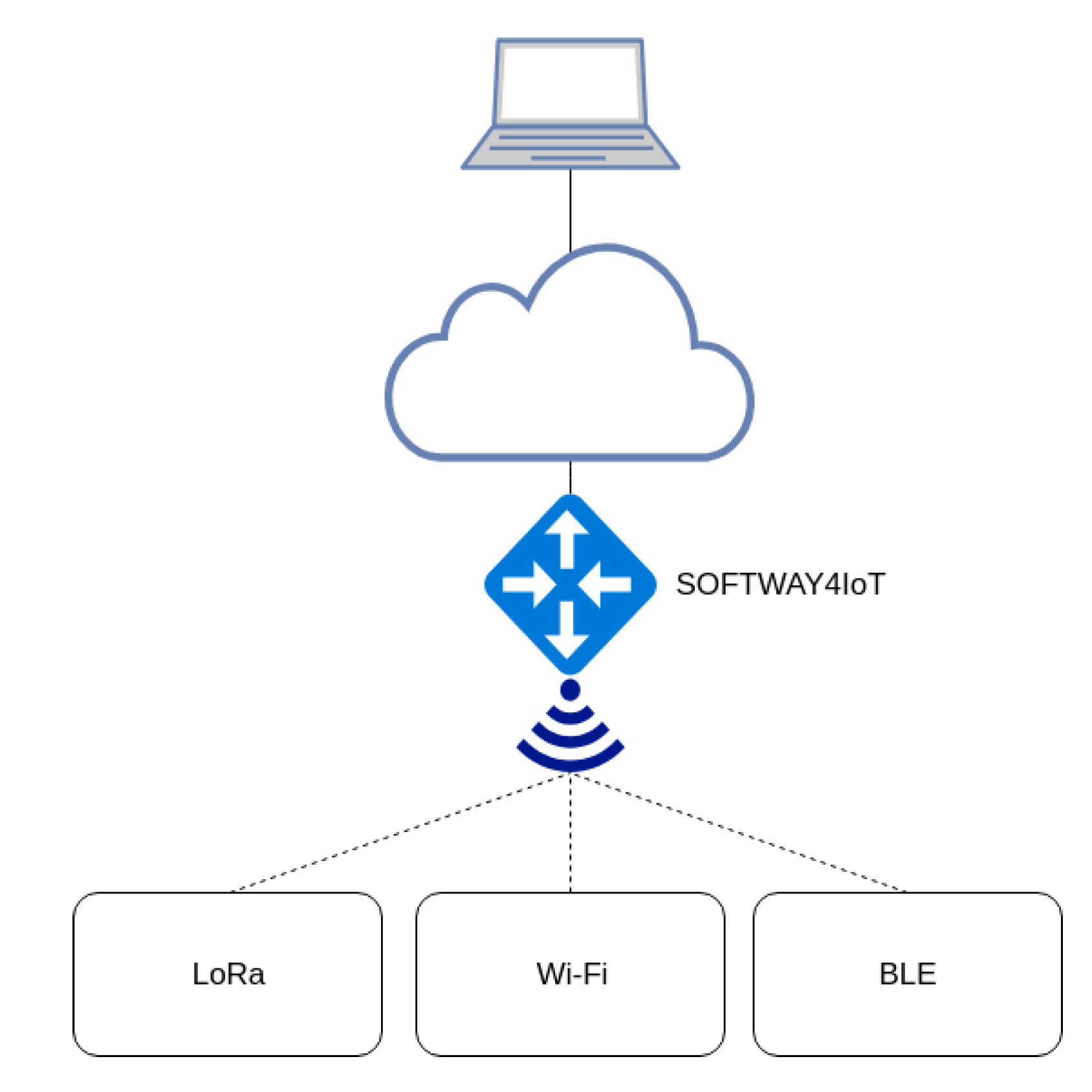
To validate our manager, we integrated it, as a component, in the SOFTware-defined gateWAY and fog computing for Internet of Things (SOFTWAY4IoT) solution [
15]. Our proof of concept is tested in a real experimental setup considering the real IoT use cases with the WiFi, BLE and LoRa wireless technologies.
Our main contributions are as follows:
A slice-based QoS management solution to allow easy integration with other SDN-based solutions (e.g., SOFTWAY4IoT) and that implements the desired QoS for each use case, considering a lightweight concept of network slicing (as a virtual network partition) to allow better provision.
Implementation and validation of different QoS models (i.e., best effort, traffic policing, IntServand DiffServ).
A comprehensive description of the implementation and tools used in the proposed solution, as well as its integration into the SOFTWAY4IoT deployment.
The remainder of this paper is structured as follows.
Section 2 provides a brief overview of the related work available in the literature.
Section 3 describes SOFTWAY4IoT, while
Section 4 describes in detail our proposed slice-based QoS manager for IoT, as well as the solution implementation.
Section 5 discusses the validation, evaluation and performance analysis results. Finally,
Section 6 presents conclusions and future work.
2. Related Work
Focusing on the specific QoS proposals using the SDN and OvS capabilities, a recent work [
16] proposed a QoS framework for network slicing in 5G networks using SDN, NFV and OvS. The experimental setup includes well-known tools such as ONOSand Mininet. However, it is not feasible for the IoT domain due to complexity.
Alipio et al. [
17] proposed the implementation of traffic policing based on priority-based packet discarding using OpenFlow 1.0. Additionally, this work chose to use a set of Raspberry Pis in order to create an SDN switch considering the Open vSwitch (OvS) capabilities for testing purposes. Moreover, our work focuses on IoT considering a well-known lightweight Ryu controller instead of POXand applying other QoS models, not only priority queuing.
Furthermore, Durner et al. [
18] presented dynamic QoS mechanisms for flows in an OpenFlow-based network, focusing their results on prioritisation and bandwidth guarantees and working for both classless and classful queueing disciplines, not considering Differentiated Services Code Point (DSCP) traffic marking. Durner realised that the use of OpenFlow on different network switches creates a variety of testing results, which must be considered when implementing QoS concepts in the network by SDN application developers.
W. Hsu et al. [
19] went into detail on a proposed architecture for QoS and Quality of Experience (QoE) mapping and application adjustment in the SDN context, taking advantage of the Ryu controller and OvS-based OpenFlow switches to do so. This work’s objective was to implement and design an application capable of perceiving the users’ QoE in order to redirect that information for the Internet Service Provider (ISP). With that valuable information, it is possible to adjust the network rules, providing a higher overall QoS. However, the only considered rate-limiting approach is the OpenFlow Meter Table [
20], discarding OvS capabilities in the QoS rules’ implementation.
Adedayo and Twala [
21] addressed both major QoS models, not taking into consideration the IoT real world in the testing methodology. This work used the Ryu controller Representational State Transfer (REST) Application Programming Interface (API) to be able to apply QoS rules in the OpenFlow OvS-based switches. Additionally, the majority of tests use Mininet [
22] in order to emulate the virtualised network, not reviewing the impact multiple clients might have on the tested network. This work did not address the concept of network slicing.
Regarding network slicing applied in the IoT domain, the IoT slicing method proposed by Casado-Vara et al. [
23] is a technique for processing heterogeneous temperature data collected by an IoT network in a smart building. The solution combines complex networks and clusters to reduce algorithm input errors and improve the monitoring and control. This work differs from ours as IoT slicing is not the network slicing concept that is applicable to SDN as in our proposal.
An approach for network slicing provisioning for IoT based on flyweight Network Functions (fNF) was proposed by Ouedraogo et al. [
24] in order to support QoS requirements to extend 5G networks. fNFs are network functions whose deployment incurs no virtualization overhead. Our work is quite close to their since they claimed an IoT I4.0 use case using the network slice. However, the work resorted to fNF and use cases considering the 5G concept offering no implementation and real-world evaluation.
An et al. [
14] proposed a slice management solution considering QoS with a focus on reducing the wireless interference among slices. The approach considers routing based on the prioritization of interference and admission control. Still, the focus of this work was not IoT, and the validations were performed over NS2 simulations.
Xiao et al. [
25] proposed an inter-operator network slice framework that is able to coordinate and access spectrum resources in both licensed and unlicensed bands. The evaluation was carried out using the LTE and WiFi networks. While our solution focuses on non-3GPP unlicensed communication, it overlooks the QoS requirements of IoT applications.
A network slicing solution [
26] for enabling the coexistence of enhanced Mobile Broadband (eMBB) and IoT sharing the RANis very interesting in the 5G domain. They validated the solution in a 5G prototype using the Open Air Interface (OAI) and FlexRAN SDN controller. However, in our work, we focus on non-3GPP unlicensed wireless communication technologies for IoT.
Wu et al. [
27] demonstrated network slicing as an enabler for Industrial IoT (IIoT) for QoS requirements consisting of multiple sensor devices with WiFi/BLE communication modules. This work relates to ours regarding the implementations and tools used (Ryu controller, OvS). However, our proposed slice-based QoS manager is implemented in a full IoT software-defined and virtualised IoT gateway employing container concepts for edge computing.
Network slicing has also been applied in LoRa networks [
28,
29] to provide specific QoS guarantees. A dynamic and adaptive inter-slicing resource reservation was proposed and evaluated in an NS3 simulation environment. However, this work did not consider the real SDN-based network for validation as done in our proposed solution.
Although the purpose of LoRaWAN networks is directed towards IoT applications, the means to carry out the integration procedures with 5G systems are not yet established as reference and technical standards in 3GPP. Hence, Navarro-Ortiz et al. [
30] presented a model for integrating LoRaWAN networks with LTE applied to the Evolved Packet Core (EPC) network. The approach does not need to change the structure of the core of the pre-existing network, and there is no need for protocols or signalling commands other than those already established. The LoRaWAN gateway acts as the User Equipment (UE). Four different approaches for integrating into the 4G structure were discussed [
31]. The integration methods covered were (i) integration via the 3GPP access network, (ii) non-trusted access by non-3GPP, (iii) encapsulating components of the LoRaWAN structure as part of the eNodeB, and (iv) virtualizing components of the LoRaWAN network architecture as part of the core network LTE. However, those works were focused on the integration of LoRaWAN with LTE without QoS requirements.
Our proposal differs from the aforementioned works as it focuses on the provision of specific QoS parameters. While we identified a few efforts in this regard, most of them were for specific application scenarios, with a strong focus on the IoT within the 5G domain. On the other hand, we are looking at non-3GPP IoT solutions over unlicensed band wireless technologies and how to provide slice-based QoS for Industry 4.0 and digital farming deployments considering a lightweight concept of network slicing.
4. Our Proposed Slice-Based QoS Manager for IoT
Our proposed lightweight slice-based QoS manager was implemented as a solution to be integrated in SOFTWAY4IoT. Our solution is lightweight since it is focused on non-3GPP IoT environments considering simpler SDN implementations besides the complete framework such as MANO, OpenDayLight or OpenStack. Hence, this section provides a detailed setup of the proposed solution to achieve QoS in slices for Industry 4.0 and digital farming deployments.
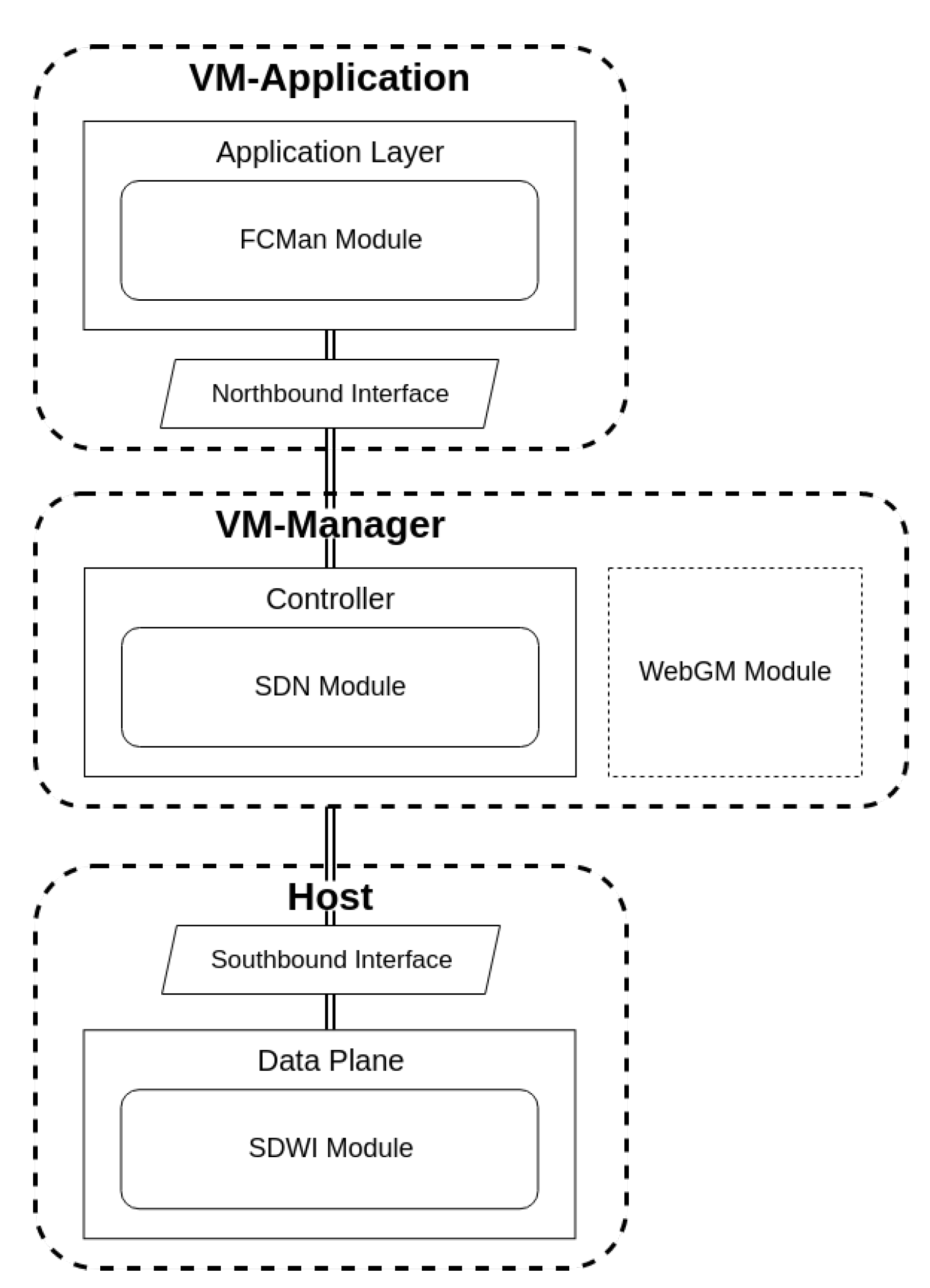
The implementation is split among three machines: Host; VM-Application and VM-Manager. The VM-Application can be described as the machine that stands between the cloud, services and tenant applications, being responsible for high-level tasks. It represents the FCMan module and, consequently, the Application Layer. VM-Manager’s primary purpose is to run the SDN module, including the lightweight Ryu controller, with the additional task of hosting WebGM and all its administration capabilities, including the services that run on other machines. Thus, from the Network Operating System (NOS) perspective, the machine can be seen as the controller API. Both VMs run on the Host in a virtualisation environment with the Xen hypervisor [
46], and all their components run inside Docker containers, guaranteeing the previously mentioned isolation of services and applications. In contrast with the VM-Application, the Host has the responsibility of performing the lower-level services and therefore represents the Data Plane. The SDWI service runs on the Host, and it communicates with the VMs employing OvS, which takes advantage of OpenFlow to update flow table entries in switches as the considered standard solution for the Southbound Interface. A schematic of the implemented setup and how it fits in the NOS architecture is depicted in
Figure 4.
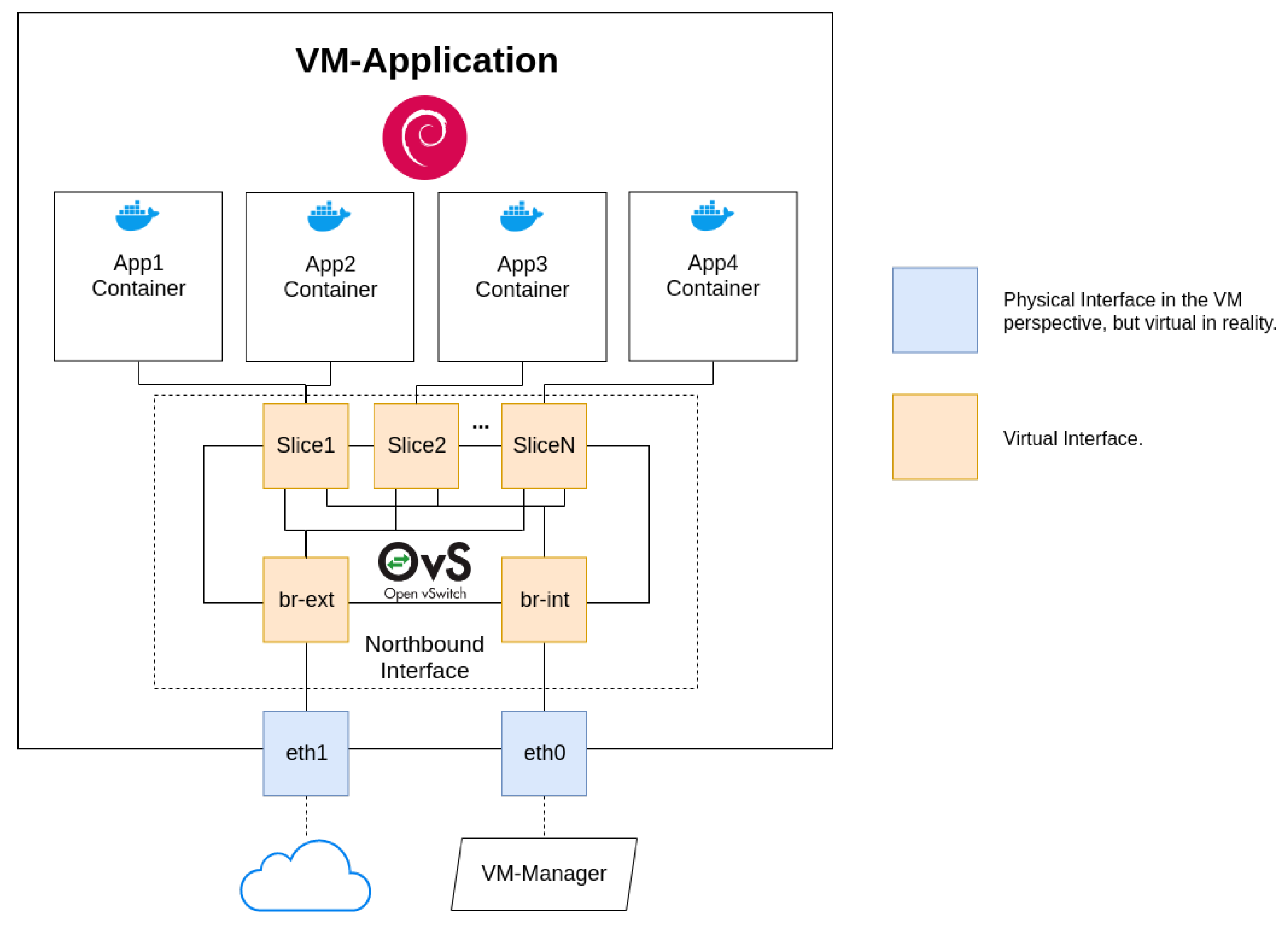
4.1. VM-Application
Since the VM is intended to represent the application layer, it has the main role of running applications with the purpose of dealing with the information coming from the bottom of the architecture stack (Data Plane). If it chooses to process information itself, then data are processed between the cloud and the source device, and therefore, fog computing is occurring. On the other hand, applications can choose to strictly redirect that information to the cloud, where it would later be computed and consequently fog computing takes place.
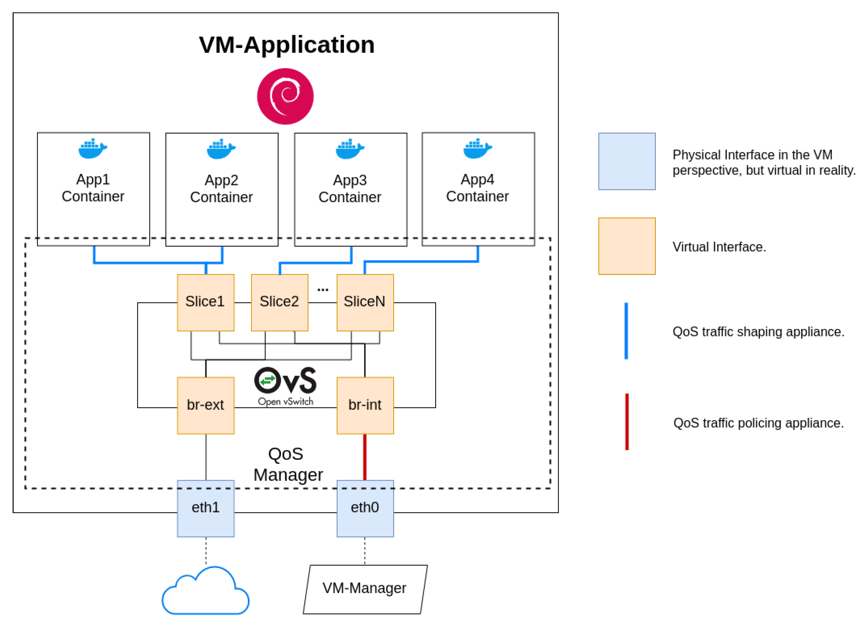
The VM-Application has two physical interfaces from its perspective, which represent OvS bridges, which are in reality virtual ones. As a matter of convention, we call them eth0 and eth1. Interface eth0 has the main role of providing applications connectivity to the controller and consequently any device available in the Data Plane. On the other hand, eth1 is the interface that connects to the cloud, being responsible for passing information if any application chooses to process information by means of cloud computing.
All applications run inside separate Docker containers, which are automatically created when the order is given by WebGM. This guarantees information isolation and the ability to provide each application different connectivity environments if needed. One of the reasons Docker containers and services are so powerful is that you can connect them together or connect them to non-Docker workloads. The deployed applications do not require being aware that they are running on Docker, or whether their peers are also Docker workloads or not, managing them independently of the platform they choose to use [
47].
In order to facilitate information exchanging between containers and the VM-Application, SOFTWAY4IoT uses OvS (Northbound Interface), allowing the use of multiple VLANs on a single bridge. Of course, this results in a more complex and virtual-oriented system, but also allows for an incredibly adaptable and scalable system. Hence, each new slice is represented by a VLAN in a newly created OvS switch, and both “physical” interfaces are bridged by
br-int (
eth0) and
br-ext (
eth1). We must remind ourselves that each slice can have more than one running application, whose connectivity is handled by its OvS bridge with a newly running port.
Figure 5 depicts the VM-Application system and networking scheme.
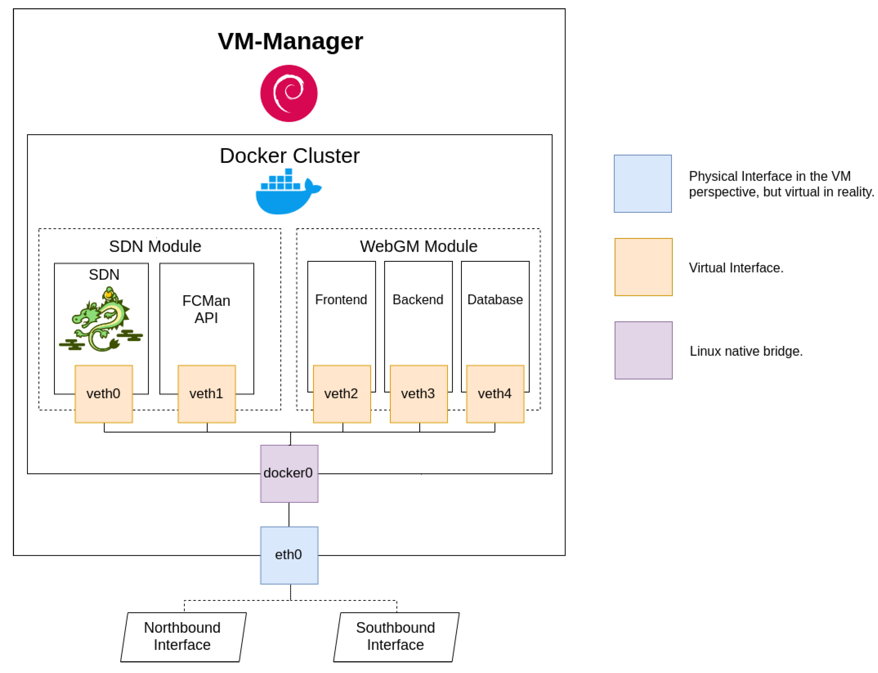
4.2. VM-Manager
The VM-Manager plays the role of the core of the considered SDN system and allows for the administration features to take place. It is essentially divided into the WebGM and SDN modules, which are segmented into several services. All components are implemented on Docker containers. WebGM is the web interface that enables any network administrator to manage all gateway functions. Its services are WebGM-Frontend, WebGM-Backend, and a database. WebGM-Frontend hosts the actual web server, which is used as a presentation layer and interacts directly with the administrator. WebGM-Backend deals with the required APIs that allow it to perform any kind of actions at a SDN level, storing the necessary information on the PostgreSQL database.
As mentioned, the SDN module has the duty to run the lightweight Ryu controller. SMan and NSMan run a container completely dedicated to be an API to FCMan. As a matter of fact, the SDN module was modified in order to support the Ryu QoS capabilities, which take advantage of a REST API and allow rules’ insertion in the network environment.
Because the machine was not in need of a scalable private network, it uses a Linux native bridge and virtual interfaces in order to access each container. Similarly to the VM-Application, it has Debian as the operating system, but only uses one physical interface from the machine perspective. The interface is called
eth0 and provides the connection to both the VM-Application and the host machine.
Figure 6 provides an insight into the VM-Manager architecture.
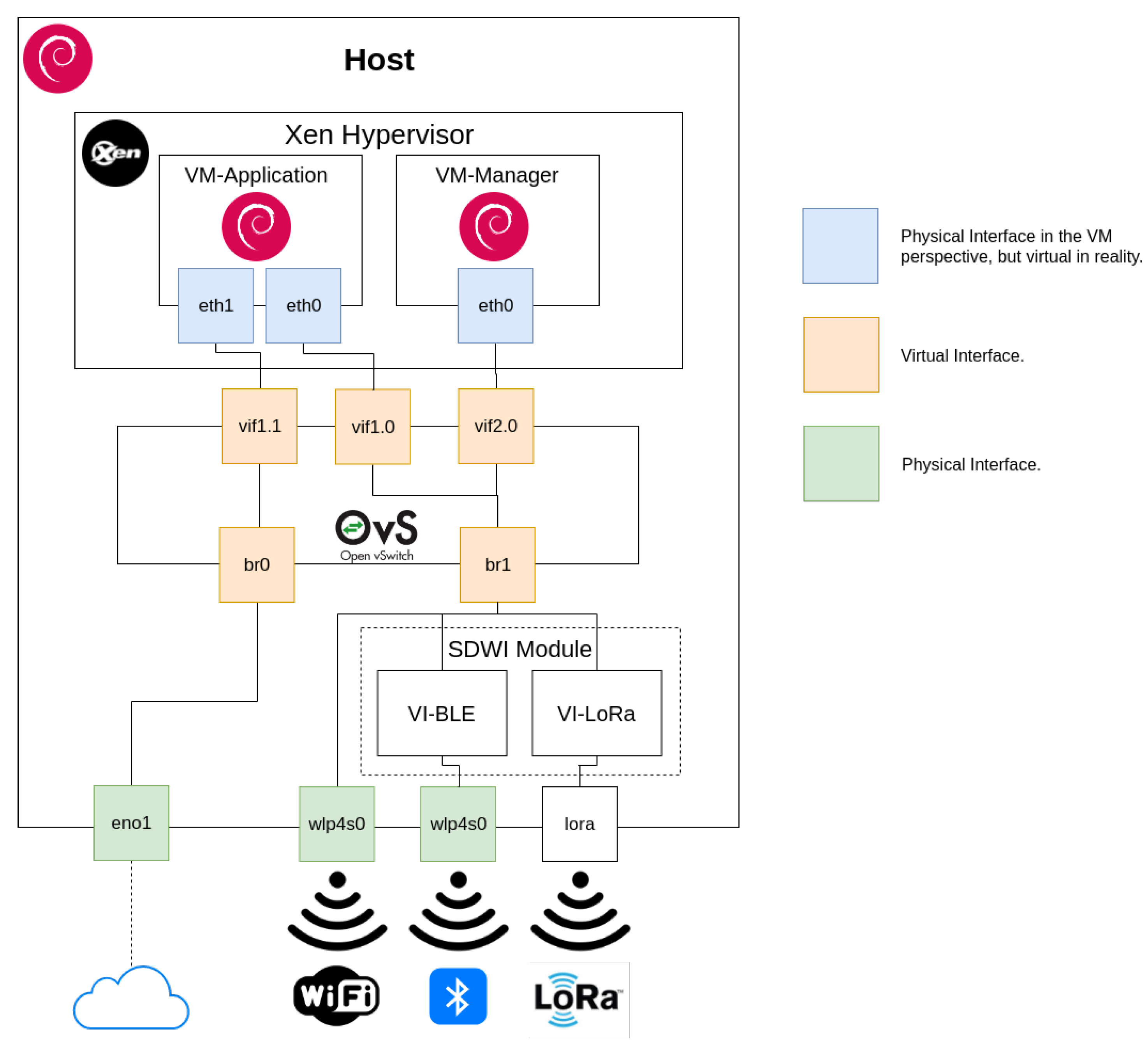
4.3. Host
The Host is running Xen hypervisor, which is responsible for the execution and management of the previous virtual machines. In order for the inter-machine communication to take place, it takes advantage of OvS and consequently OpenFlow, which functions as the system Southbound Interface. In addition to that, it is running a modified SDWI module and tries to make the best of virtualisation to perform its actions.
Figure 7 provides a visual clarification of the Host system. Regarding its networking architecture, it has two physical interfaces. The Ethernet
eno1 is responsible for providing Internet access, both to the host machine and the VM-Application through the OvS system. Besides that, the wireless interface (that supports both WiFi and BLE) is intended to enable gateway connectivity to devices that wish to communicate via those technologies. In order for the VMs to be reachable, OvS uses its bridging capabilities,
eno1 now being represented by
br0, where
wlp4s0 and the
sdwi module are bridged by
br1, accessing both systems through OvS virtual interfaces.
In addition, as previously stated, the Host runs the SDWI module. As we do not use SDR in this work, the SDWI module is divided in two services VI-BLE and VI-LoRa in order to represent our virtual interfaces of wireless technologies.
4.4. Data Plane Networking
The goal of this work is to support WiFi, BLE and LoRa wireless technologies for IoT. In order to do so, the Gateway requires handling the reception of their signals, interpreting them and redirecting to the above architecture layers. Additionally, it is necessary to consider that the raw BLE and LoRa technologies may signify problems in the information exchanging process. Those problems can be solved by means of a renovated SDWI module, and only the LoRa physical interface is left for the gateway to be able to deal with the necessary radio services.
4.4.1. LoRa Physical Interface
In this work, the radio communication system components are not dealt with through software implementations. As seen in the Host system architecture (
Figure 7), it is clear that the machine wireless interface supports BLE and can be used to fetch data from LoRa technology end devices. On the other hand, LoRa still needs a physical interface ready to receive information that will be provided by the technology devices. For that reason, an Arduino Uno [
48] device along with a Dragino LoRa Shield [
49] were used as the information transceiver, redirecting to the SDWI module through its serial port. In brief, the shield was chosen due to its configuration flexibility, Arduino compatibility and low power consumption, representing a good choice for the technology access point.
It was necessary to use RH_RF95 [
50], a driver that enables the reception of datagrams via a LoRa capable radio transceiver, which is also capable of configuring its signal power and operating frequency.
4.4.2. VI-BLE and VI-LoRa in the SDWI Module
It is important to notice that SOFTWAY4IoT uses IP when it comes to the Network Layer of the OSI Model. Therefore, having in mind the BLE and LoRa protocol stack lacking the IP, those technology devices would not be able to properly communicate with the gateway. Hence, the new version of the SDWI module is required to perform the received packets’ IP encapsulation and their redirection to the assigned OvS bridge. For that reason, two new components are created, VI-BLE and VI-LoRa.
All BLE devices use the Generic Attribute Profile (GATT), which can be translated into APIs offered by operating systems that support BLE technology likely being based on its concepts [
51]. GATT is built on top of the Attribute Protocol (ATT) and establishes common operations and a framework for the data transported and stored by a generic data protocol [
52]. In order to better understand how VI-BLE works, it is necessary to inspect the profile terminology, which works around the server/client relationship and has essentially five important concepts: Client; Server; Profile; Services; Characteristics.
Because BLE focuses on low power consumption, their devices are not willing to send information by themselves and need to be requested to do so. Hence, the GATT client (VI-BLE on the Host) has the responsibility to start a transaction on the GATT server (a given peripheral device), which suggests a connection interval that the client will respect in order to inspect if any new data are available.
VI-BLE takes advantage of GATT and one of its Python modules [
53] in order to fetch information from the intended BLE devices, using the Host Bluetooth adapter to do so. Because it might be interesting to filter the devices VI-BLE wants to connect to, a JSON file is kept containing a list of MAC addresses. Additionally, that file has a related IP address to each assigned device, which is used to create a Linux virtual interface and consequently send the fetched information to the Gateway upper layers by means of MQTT.
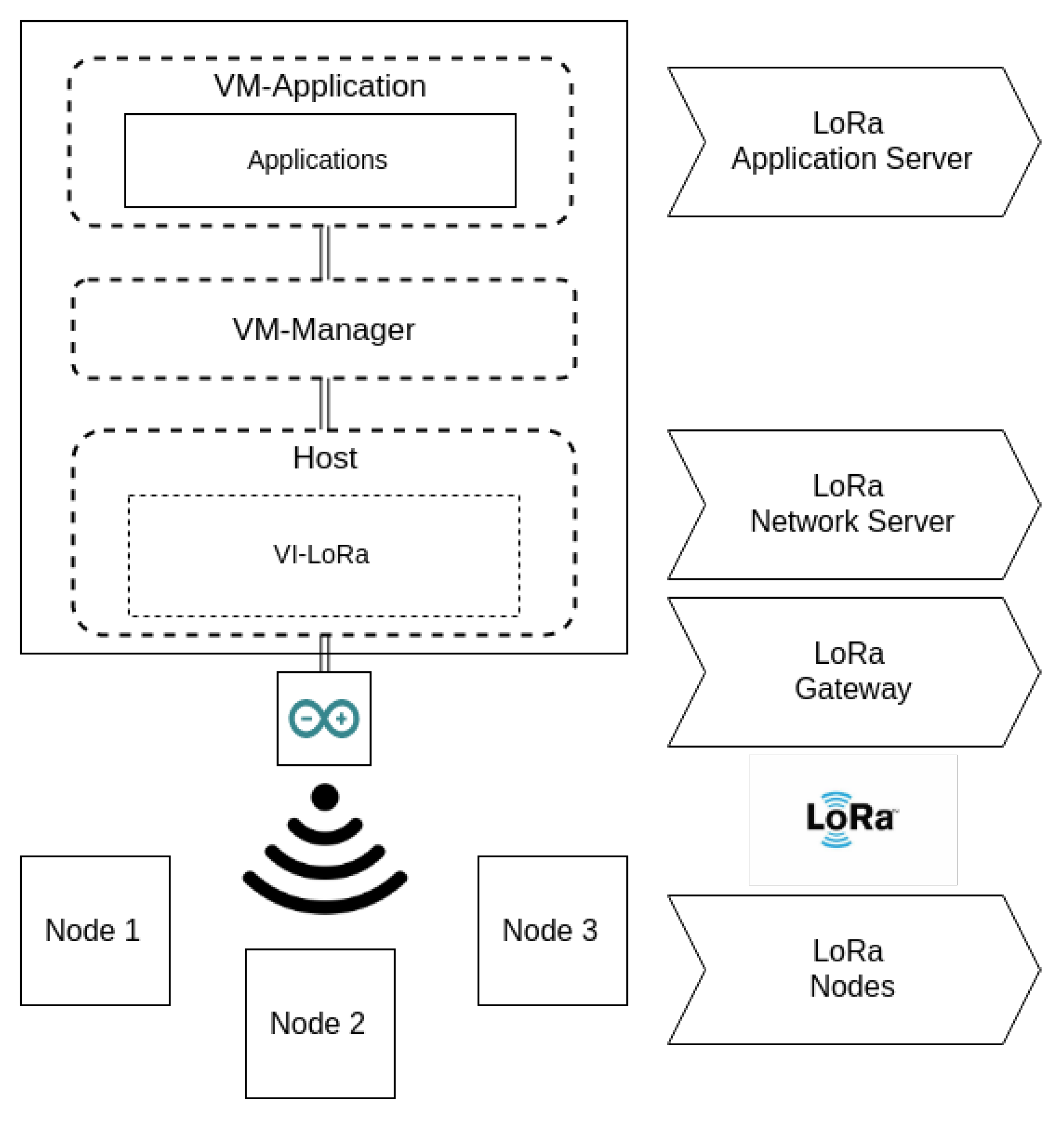
The used LoRa network architecture is deployed in a star topology in which nodes, gateway, network servers, and application servers are placed. A node collects sensor records and sends them to a gateway by using single-hop wireless communication with LoRa modulation. The gateway is connected to a central network server and acts as a bridge between the node and the network server, converting radio frequency signals into IP packets. The network server determines which data belong to which node and removes duplicated data, redirecting them to the Application Layer. Hence, the applications that reside on the top of the SDN architecture are used to collect and analyse data from nodes [
54].
As might be noticed, in this work solution context, the LoRa network Application Server is represented by the running applications on the corresponding VM. Additionally, the component VI-LoRa joins forces with Arduino LoRa Shield in order to perform not only data interpretation, but also packet IP conversion. Because of that, it is responsible for functioning as both the Network Server and Gateway in the technology network architecture. The nodes are the end devices whose information is fetched from the sensors. The LoRa network architecture and its relation with SOFTWAY4IoT can be seen in
Figure 8.
The utilised Arduino LoRa Shield device is able to interpret data by itself, and contrary to BLE devices, LoRa nodes do not need to be stimulated in order to send the fetched sensors data. Hence, when a node connects to SOFTWAY4IoT, both IP and MAC addresses are generated and kept in a small database, which resides inside the SDWI module. After receiving the sensor’s information, under the same approach of VI-BLE, VI-LoRa uses MQTT in order to exchange data with applications.
4.5. Network Architecture Overview
It is clear that most networking on the solution VMs take advantage of the OpenFlow protocol in order to properly function. Additionally, it might be interesting to understand which protocols the implementation takes advantage of to communicate.
Figure 9 provides an overview of the solution network architecture and the used protocols on each link.
Hence, the Host is responsible for dealing with the Data Plane related tasks of the system architecture. If devices choose to use WiFi in order to access the gateway, traffic enters directly to the system Southbound Interface. On the other hand, in the case of BLE and LoRa devices, data firstly go through the SDWI module in order to be encapsulated. All those communication processes take advantage of the OpenFlow and MQTT protocols.
The VM-Manager is responsible for running the administration features by means of Docker containers. It provides lodging for the SDN module, which includes the lightweight Ryu controller and FCMan API. Additionally, a web interface with the purpose of facilitating the network administrator actions is hosted on the machine. Furthermore, this important component can communicate with the VM-Application components through the system Northbound Interface. The VM-Application is responsible for dealing with the slice related networking, assigning each one to a newly created OvS switch. Additionally, it has the task of running all slice applications on separate Docker containers. All those actions are orchestrated and supervised by the VM-Manager, where the controller resides.
4.6. Slice-Based QoS Manager Solution
A functional SDN gateway is running and capable of fetching data from all proposed wireless technologies devices. Additionally, those devices can be assigned to different network slices (as virtual network partitions) if needed. However, all of them are being given the same connectivity conditions, which might not be the ideal scenario if their production environment is not the same. Hence, the solution is in need of a component that would be capable of providing each virtual network partition different QoS levels in order to better fit its use case application.
Figure 10 represents our proposed slice-based QoS manager solution placement. The solution developed can provide each slice (virtual network partitions) with different QoS levels in order to better fit the application requirements. The Northbound API can program the Data Plane to perform QoS, and because of that, the VM-Application is the machine where the slice-based QoS manager solution takes place.
The current solution has several lightweight SDN related running components, which are capable of setting QoS levels in which we have modified the original SDN module of SOFTWAY4IoT. The network administrator is now able to perform REST API requests in order to install QoS rules. It must be noted that despite all those requests, rules are in reality imposed by OvS and OpenFlow. Hence, the Ryu REST API enables the user to perform requests in order to enable a more straightforward QoS implementation at an OvS and OpenFlow level. However, as the SDN core resides on the controller, the administrator can apply QoS on OvS switches that are connected to the Ryu controller.
Taking a closer look at the VM-Application architecture and how it relates to OvS, all information that comes from the bottom layers passes through the VM eth0 interface and consequently br-int as well. Each flow is then divided on br-int, taking the direction of the bridge that belongs to the destination slice. On that bridge, several ports are placed where they are meant to provide a connection to their application containers.
On the other side, it is crucial to understand that policing can be applied on traffic that is entering a given OvS switch. Additionally, it should be noted that br-int is connected to any container bridge through a patch port. OvS documentation claims that bridges that are connected through patch ports behave like a single one, which translates in the Northbound Interface to being represented by a switch in the QoS manager perspective.
It is essential to mention that it could be overcome if it was chosen to implement those rules utilising the Linux Traffic Control (TC) tool [
55]. However, as the OvS itself does not take advantage of TC in order to perform its QoS implementations, the implementation of those features that are not currently supported by OvS is not in the scope of our work.
With that in mind, considering the current SOFTWAY4IoT implementation, policing is applied to the port that is meant to provide a connection to the lower layers of the SOFTWAY4IoT architecture (br-int of VM-Application). Consequently, this kind of traffic limitation affects slices from a single-level perspective, and their traffic splits in order to respect those limits. Nonetheless, traffic shaping QoS rules are going to be applied in ports that allow traffic to egress the Northbound API environment, making sure our developed solution can be actuated in both an application and slice in an independent way.
The next subsection explains in detail how our slice-based QoS manager solution can apply QoS rules. While Ryu provides a built-in REST API that enables QoS rules’ application, those are implemented by OvS and OpenFlow features. Because of that, despite having different roles, it might be interesting to explain how those tools are put together in order to implement the major QoS models’ characteristics. Additionally, each tool is inspected with the purpose of elaborating how its QoS implementation architecture can be related to our solution.
4.6.1. Open vSwitch Role
There are mainly two ways of providing QoS with OvS. For traffic that ingresses into a switch, OvS can perform policing [
20], which is the action of dropping packets whenever the allocated network resources have been exceeded. When traffic is egressing from a switch, OvS supports traffic shaping. Unlike policing, shaping slows down the packet transmission or reception instead of dropping the packet, inserting it in queues, waiting to be dispatched. It is essential to mention that OvS does not implement QoS by itself, taking advantage of Linux QoS features previously built in its kernel.
4.6.2. Linux Traffic Control
Linux TC is a handy utility that has a wide range of applicability and is available in standard Linux distributions. The technology has traffic control related features [
55], which rely on shaping, scheduling, policing and dropping. The Qdiscs Linux TC implementation is the basis of traffic control. There are several types of both classless and classful Qdiscs. On the classless side, we have First In-First Out (FIFO), Random Early Detection (RED), Stochastic Fair Queuing (SFQ) and Token Bucket Filter (TBF). Classful Qdiscs are Class-Based Queuing (CBQ), Hierarchical Token Bucket (HTB) and Priority Queuing (PRIO).
In our solution, we considered the HTB, which has shaping capabilities based on TBF and has the ability of classes prioritisation. TBS is the right choice when it comes to limiting traffic to a configured maximum rate, dealing exceptionally well with significant amounts of bandwidth. HTB works by implementing a well-composed link sharing hierarchy of classes with an emphasis on conforming to existing practices. It facilitates guaranteeing bandwidth to classes, while also allowing the specification of upper limits to inter-class sharing.
4.6.3. OpenFlow Role
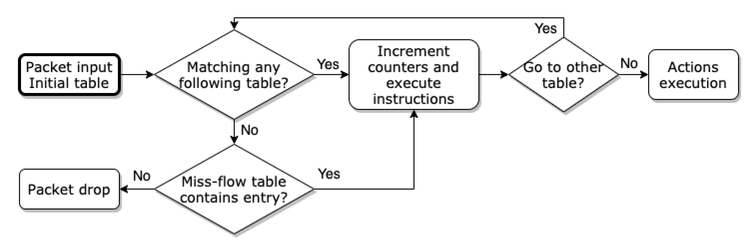
OpenFlow contains interesting features that can prove to be essential for the slice-based QoS manager’s successful functioning. The slice-based QoS manager takes advantage of the protocol and inherently contains three main components: flow tables; group table; openflow channel. Flow tables and the group table are usually put together and allow inspection and forward packets to a given port. On the other hand, the OpenFlow channel is used by Ryu in order to apply any rules using the OpenFlow protocol. In light of this, the controller can choose to insert, update and remove flow entries from flow tables, in a reactive (based on receiving packets) or proactive way. Hence, flow entries are put together in order to form a flow table, which consists of several characteristics.
Figure 11 illustrates how packets are handled at the OpenFlow protocol level in our solution. The flowchart represents the role of OpenFlow in our slice-based QoS manager solution. Due to its matching capabilities, it is possible to distinguish packets based on its headers and its ingress port. It is essential in flows’ identification, where the IntServ model is applied. Additionally, because in order to perform traffic classification, DiffServ uses a six bit DSCP within the differentiated services octet, services’ differentiation is also possible. Furthermore, based on the performed matching, packets can be redirected to any OvS created queue and obey distinct queue characteristics.
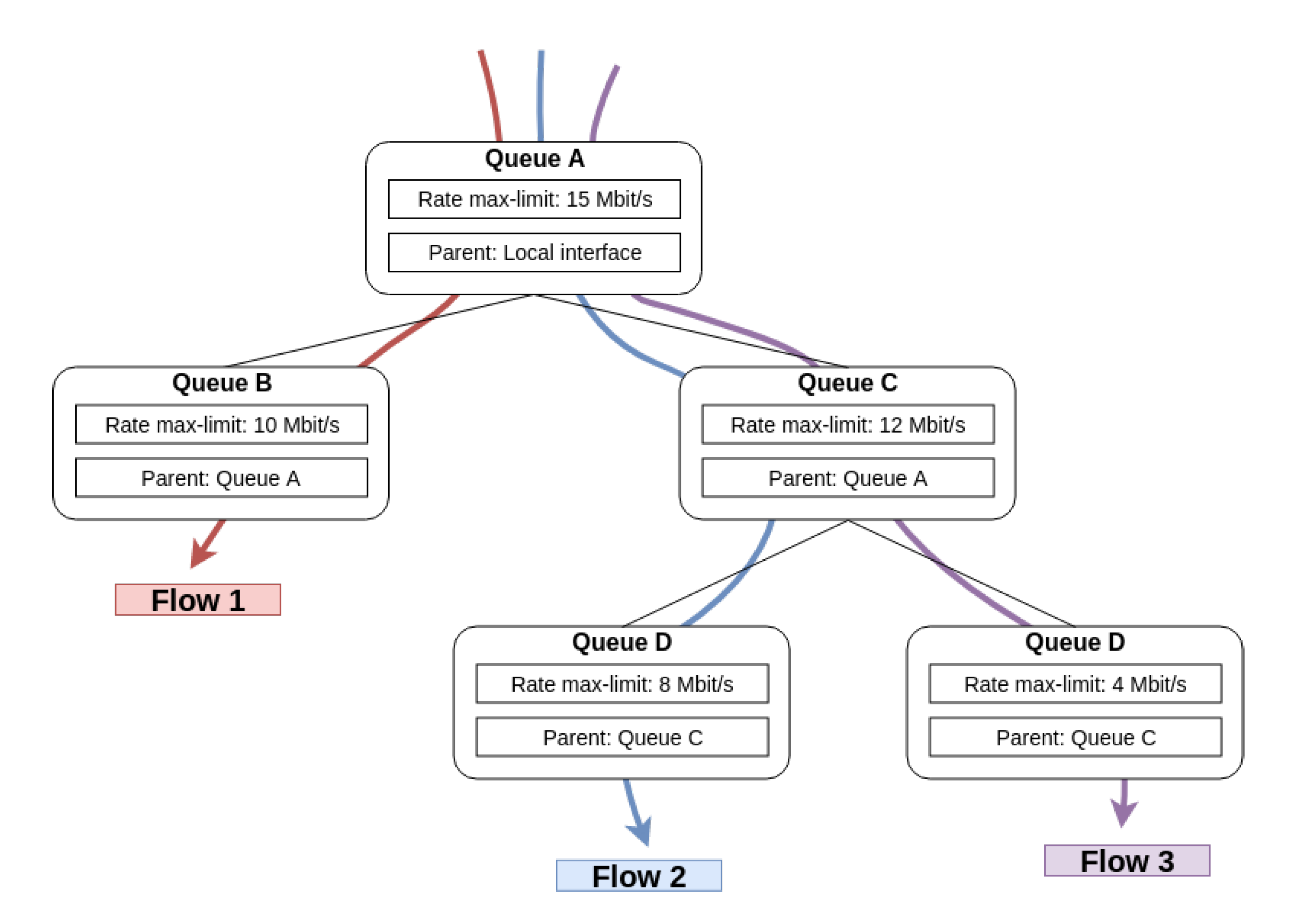
Hence, because the module takes advantage of OvS and OpenFlow, it is able to implement the major QoS models, which can be calibrated in order to attend to several scenarios. In order to aid the understanding of what both technologies are able to do when they join forces, an example configuration can be found in
Figure 12.
4.6.4. Per-Interface Policing
We developed and implemented our slice-based QoS solution using traffic policing on the ingressing ports of a switch. Rules are set up to limit the transmission rate on a given interface by setting the ingress policing rate and ingress policing burst. This is a form of QoS that drops packets received over the configured maximum bandwidth. The implementation of policing is usually less accurate and less effective than egress QoS. For its functioning, it uses a token bucket approach, where the size of the bucket corresponds to ingress policing burst. Initially, the bucket is set as full. When a packet is received, its size is converted to tokens and compared to the number of tokens currently in the bucket. In the eventuality of the required number of tokens being available, they are removed, and the packet is forwarded. Otherwise, the packet is dropped. On the other hand, when the bucket is not full, it is refilled with tokens at the previously configured maximum rate.
4.6.5. Per-Flow QoS: IntServ
Our per-flow slice-based QoS implementation adds queue settings and rules to reserve network bandwidth, taking advantage of egress traffic shaping to do so. Hence, the target interface is not only limited to a specific bandwidth, but instead, distinct known applications or services can be assigned a bit rate using IntServ classification [
21]. Traffic shaping is configured using the QoS and queue OvS tables and uses OpenFlow in order to identify and separate services in the solution SDN environment.
4.6.6. DiffServ QoS
While per-flow QoS can have a good behaviour as communication flows increase, the flow entries’ number, which is set for each OvS switch, also grows. Hence, the per-flow QoS is considered not to be scalable. Contrarily, the DiffServ slice-based QoS implementation divides flows into the several QoS classes at the domain entrance (br-int) and applies DSCP marking, matching them with the associated queues in each slice’s OvS switch. Therefore, packets will be forwarded according to the first six bits of the Type of Service (ToS) field in its IP header.
5. Validation, Evaluation and Obtained Results
In order to automate the execution of administration features that WebGM provides, a Python script was developed whose purpose is to take advantage of both modules, FCMan and SDN REST API. By doing so, it is possible to create slices, run containers and register the required IoT devices in an automated fashion every time a test is performed. All clients ran in the Host machine. Because end devices (things) must be somehow represented, several SDWI-like Linux virtual interfaces were created with a given IP and random MAC addresses. As a result of that, having in mind IoT characteristics, all the tests realised can be related to the implemented solution scalability potentialities.
With virtual end devices, it is now possible to test its connectivity by binding the process to the intended network interface. However, in order to better analyse the solution performance, the injection of stress through traffic generation is needed. Iperf3 [
56] was used to perform active measurements of the maximum achievable bandwidth. Due to Iperf3’s lack of support for fetching the server statistics output, its source code was modified and already submitted via pull request to the GitHub official repository [
57].
On top of the gateway network architecture, each client requires an Iperf3 server waiting to be connected and ready to report its statistics results. Hence, the VM-Application Docker containers were running in order to accommodate them, resulting in traffic flowing through all the SDN architecture layers. Each server was accessible through the same IP address, but different ports.
5.1. Best Effort
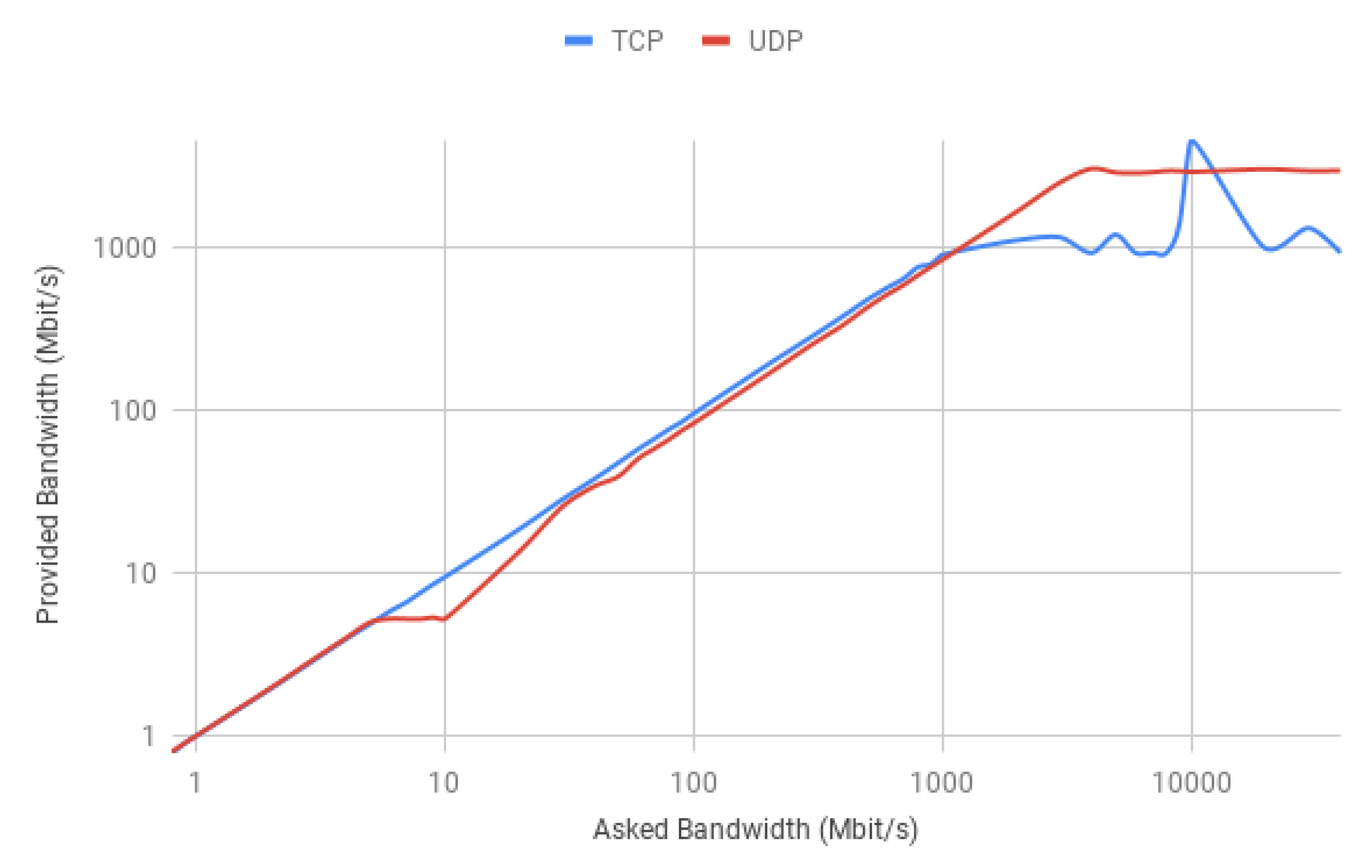
Firstly, it is important to understand the natural characteristics of the default (best effort) implementation. Hence, it is pertinent to test its functionalities without taking advantage of the slice-based QoS manager. The main purpose is to find what are the implemented solution limitations, showing potential drawbacks that some processing environments and network characteristics may provoke.
Hence, one interesting result would be to find what is the maximum achievable bandwidth that the default version of our implementation can handle. The test was performed for two scenarios, using the TCP and UDP transport layer protocols. Only one Iperf3 client was used in each case, which gradually increased the connection requested bandwidth. The test result is depicted in
Figure 13.
As can be seen by the above chart, despite one noticeable peak of 4.6 Gbit/s, TCP stabilised roughly at 1 Gbit/s, while UDP found a balance at approximately 3 Gbit/s. The observed chart reports that TCP has a stabilised best effort bitrate smaller than UDP. The proposed solution addresses two scenarios where several end devices are allowed to exist and that may serve a wide range of applications. Hence, it showed how both protocols behave when traffic provided by different devices is simultaneously flowing through the solution.
5.1.1. Multiple Clients
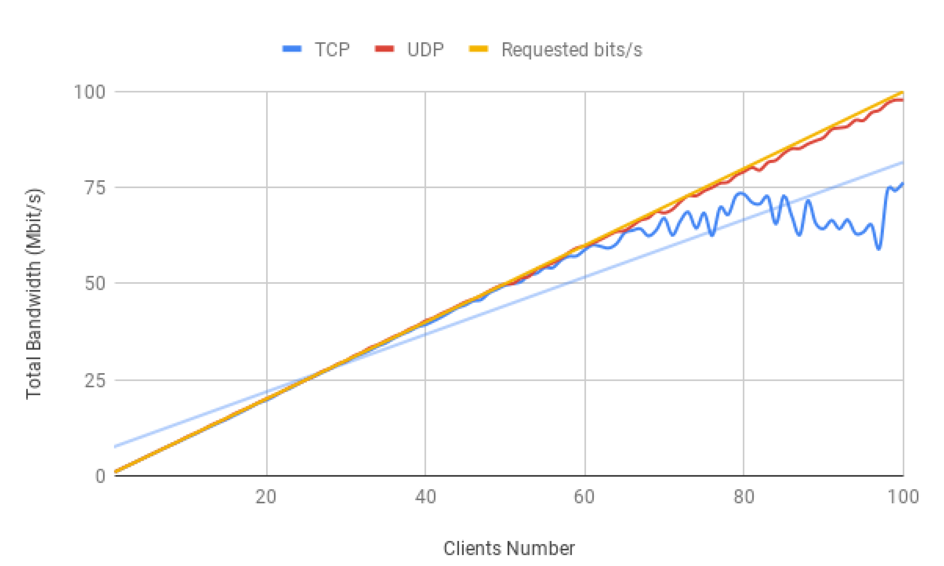
The solution is intended to deal with several client connections. Hence, it is important to analyse the resultant impact of growing devices in the gateway networking environment. In order to do so, the same protocol comparison was made where each client was imposing a bit rate of 1 Mbit/s. It should be mentioned that only one slice was considered, and the tests below were not performed simultaneously.
Figure 14 shows the total bit rate of the TCP and UDP protocols resulting from a growing client number.
TCP clients suffer and cannot keep up with the requested bandwidth, which at roughly 70 clients, begins to deteriorate. Understanding the performance of the system resources is important and might reveal some limitations of an SDN implementation. Hence, usually, software performance is directly limited by hardware, and the Iperf3 CPU utilisation reports should be taken into account.
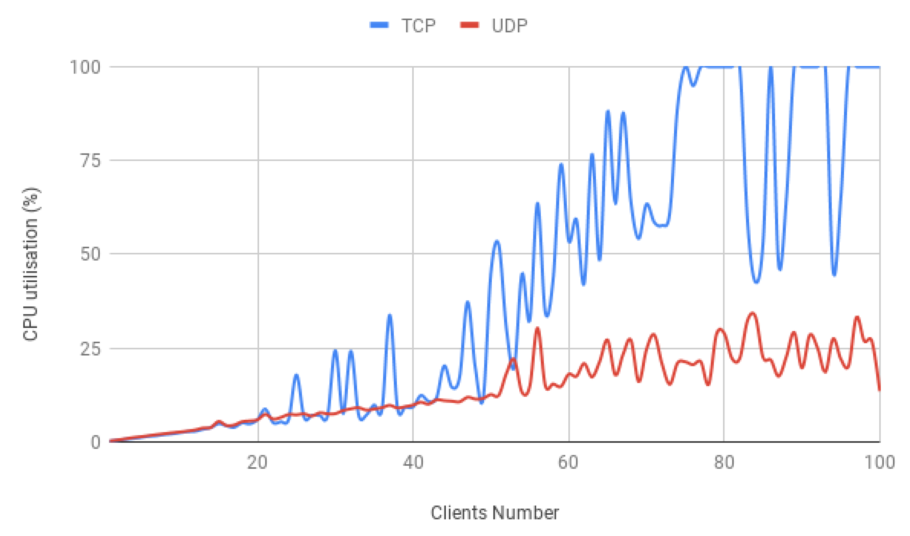
Despite not being a surprise, it is clear that the CPU usage is damaging the TCP scenario performance as shown in
Figure 15. As was anticipated, the bit rate degradation starts when the machine enters full processing power, causing the total clients’ bandwidth not to go further than 75 Mbit/s. Natural intuition would blame the protocol characteristics, which contrary to UDP, is connection oriented and focuses on reliability.
5.1.2. Multiple Slices
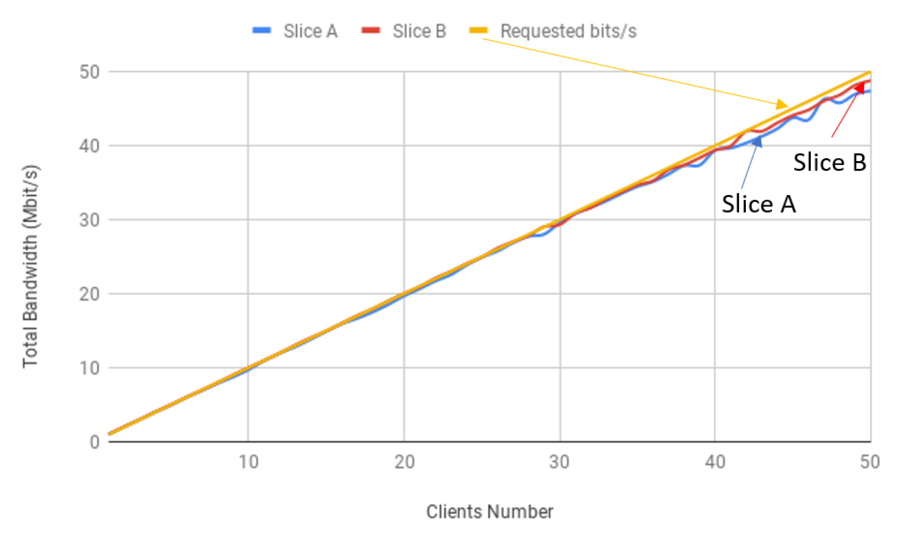
Since our goal is to address multiple use cases, it is relevant to test two simultaneously running slices in a best effort approach. The testing scenario addresses both network segments with 50 clients each, which are instructed to inject 1 Mbit/s per interface with Iperf3 default packet sizes in the gateway. The test also considers the previously mentioned protocols where Slice A and Slice B are using TCP and UDP, respectively, to illustrate better and differentiate each slice.
Figure 16 shows a comparison of both slices’ achieved bandwidth.
As expected, the implemented solution can handle several end devices, even if their destination slices happen to be different. Because this work’s proposed solution addresses two use cases, the evaluation considered two slices as well. Despite the commitment to perform exhaustive tests, it is crucial to understand that the main objective is to find the QoS implementation that would better fit the Industry 4.0 and digital farming environments.
5.2. Traffic Policing
Policing can be implemented on interface
eth1 of the VM-Application, mainly because it represents the interface that deals with traffic flows entering the system from the outside. On the other hand, each created slice port represents the way out of the whole OvS system, which enables its usage for outgoing traffic shaping. Because of that, traffic policing is inevitably applied to all the gateway created slices, affecting them in a single-level fashion. Contrarily, shaping is applied to each slice independently, where rules are set and are inherent to one single virtualised network segment. Hence, it is important to mention that besides the default flow entries applied by the Ryu controller, no flows entries are applied by our proposed slice-based QoS manager. The evaluation is intended to illustrate that it affects all slices when the solution is taking advantage of it. In light of this, the clients’ number was gradually increased in two simultaneously running slices whose combined bit rate was limited by 50 Mbit/s. All clients were attempting to poke the server with 1 Mbit/s, using TCP. Additionally, the defined policing burst value was set as 10 Mbit/s. The slices’ aggregated bandwidth is observable in
Figure 17.
As can be seen, both slices are being affected when their bit rates reach 25 Mbit/s. This can be explained by their aggregated bandwidth of 50 Mbit/s at a time, which is the rate limit that the traffic policing implementation imposed. The OvS documentation states that defining a burst size to be a sizeable fraction of the policing maximum limit rate enables the flow to more easily achieve the full rate. However, if the defined burst size is set to be a significant value, the client can notice an average rate slightly higher than the specified maximum one [
20]. Hence, because the test defined burst value is around 20% of the maximum rate limit, the slices’ aggregated bandwidth is moderately overcoming it.
5.3. Per-Flow QoS: IntServ
The slice-based QoS policing is actuated at an interface level, dropping excess traffic that crosses into it and not taking advantage of QoS queues to do so. On the other hand, traffic shaping is applied on an OvS port, allowing multiple queues’ creation and flow control on its OvS switch side. Hence, it enables the use of a set of IntServ rules in our proposed solution.
As our goal is to address two use cases, it is vital to guarantee the stability of the implemented scenarios having two network slices in mind. Hence, all clients are required to possess an IntServ classification (flow entry) that would forward them based on their destination IP port. This feature results in additional traffic in the OpenFlow switch table. The details of the implemented slice-based QoS queues are shown in
Table 1.
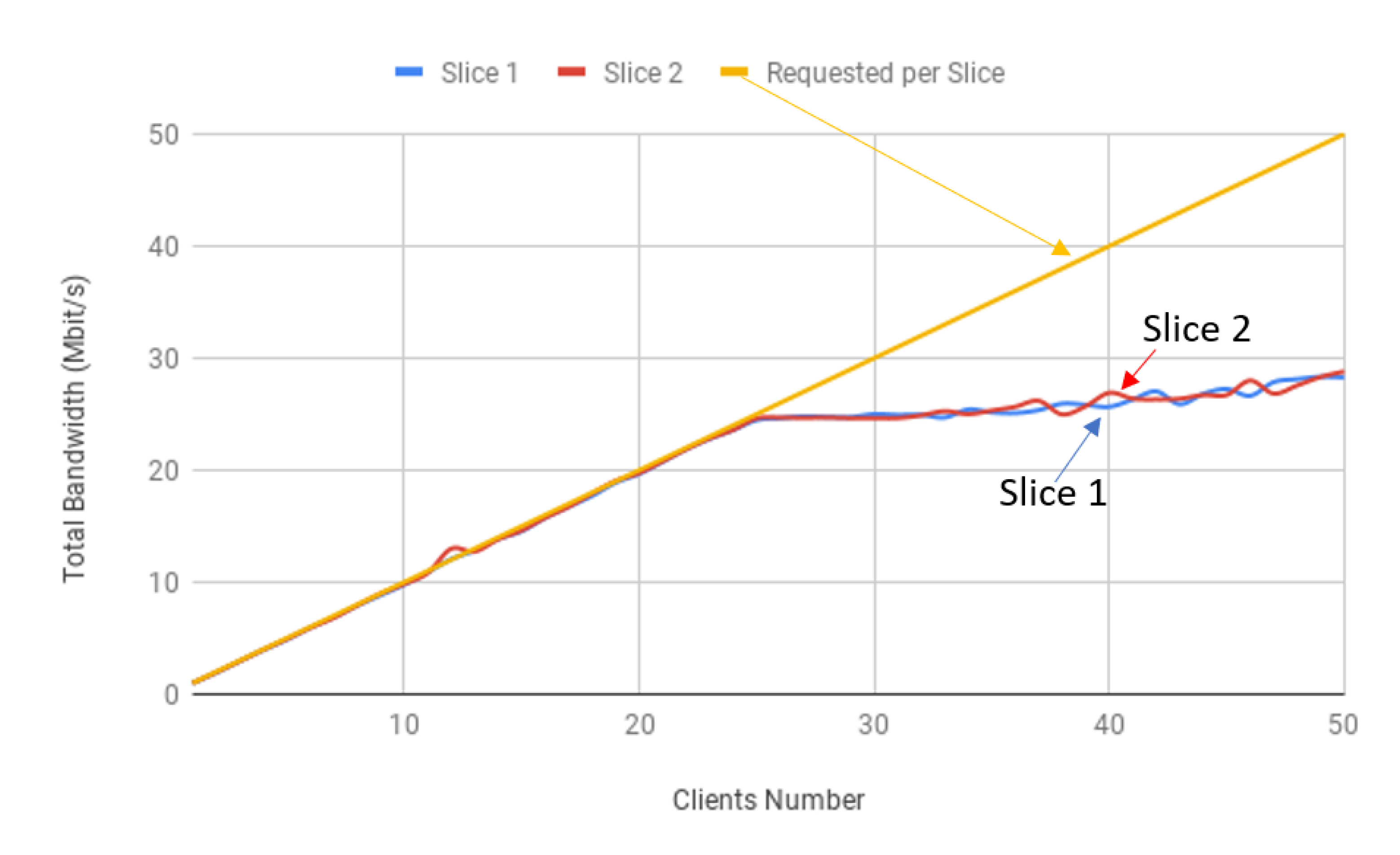
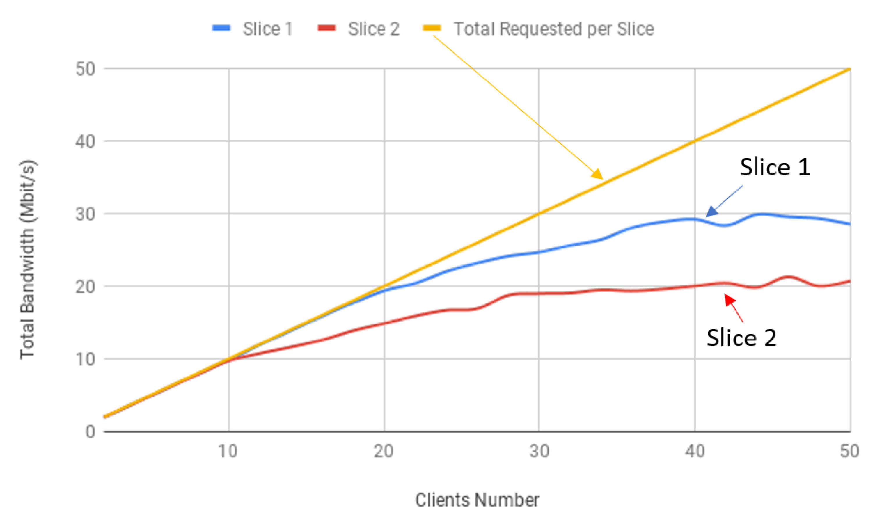
The comparison of both slices’ achieved bandwidth is depicted in
Figure 18, showing the efficiency of our solution. Clients were behaving in the same way as in the traffic policing evaluation, using TCP and injecting 1 Mbit/s each. With that in mind, Slice 1 (ID = 1) is expected not to go beyond 30 Mbit/s (ID 1 = 20 Mbit/s and ID 2 = 10 Mbit/s), while Slice 2 (ID = 2) should stabilise around 20 Mbit/s (ID 1 = 15 Mbit/s and ID 2 = 5 Mbit/s).
5.4. DiffServ QoS
Contrary to IntServ, DiffServ seeks to use methods in order to categorise traffic into distinct classes. The solution Northbound core OvS switch is not able to apply the tool QoS rules, which forces them to be implemented in each slice switch port instead and creating the so-called DiffServ domains. However, OpenFlow related parameters can still be applied in br-int, which allows our slice-based QoS manager to take advantage of it in order to mark DSCP values. Moreover, since IP headers contain the DSCP bit field, which is positioned in the ToS octet, it is possible to define OpenFlow rules that mark and redirect traffic flows based on their packet’s DSCP value. Hence, the services’ differentiation also allows OvS to define traffic prioritisation within a given slice, which causes important queues to receive all the excess bandwidth that they can use before less prioritised queues receive any.
Our proposed slice-based QoS manager provides an OvS and OpenFlow level API to allow classification and to differentiate services within each slice domain. Therefore, in the case of prioritisation requirements, the relation between them and DSCP values has to be set by the gateway administrator. We followed the commonly utilised DSCP values’ list, which is described by RFC 2475. DiffServ analyses the pre-defined traffic classes on each domain node. Thus, our model can differentiate flows based on matching parameters. The defined queue rules are shown in
Table 2.
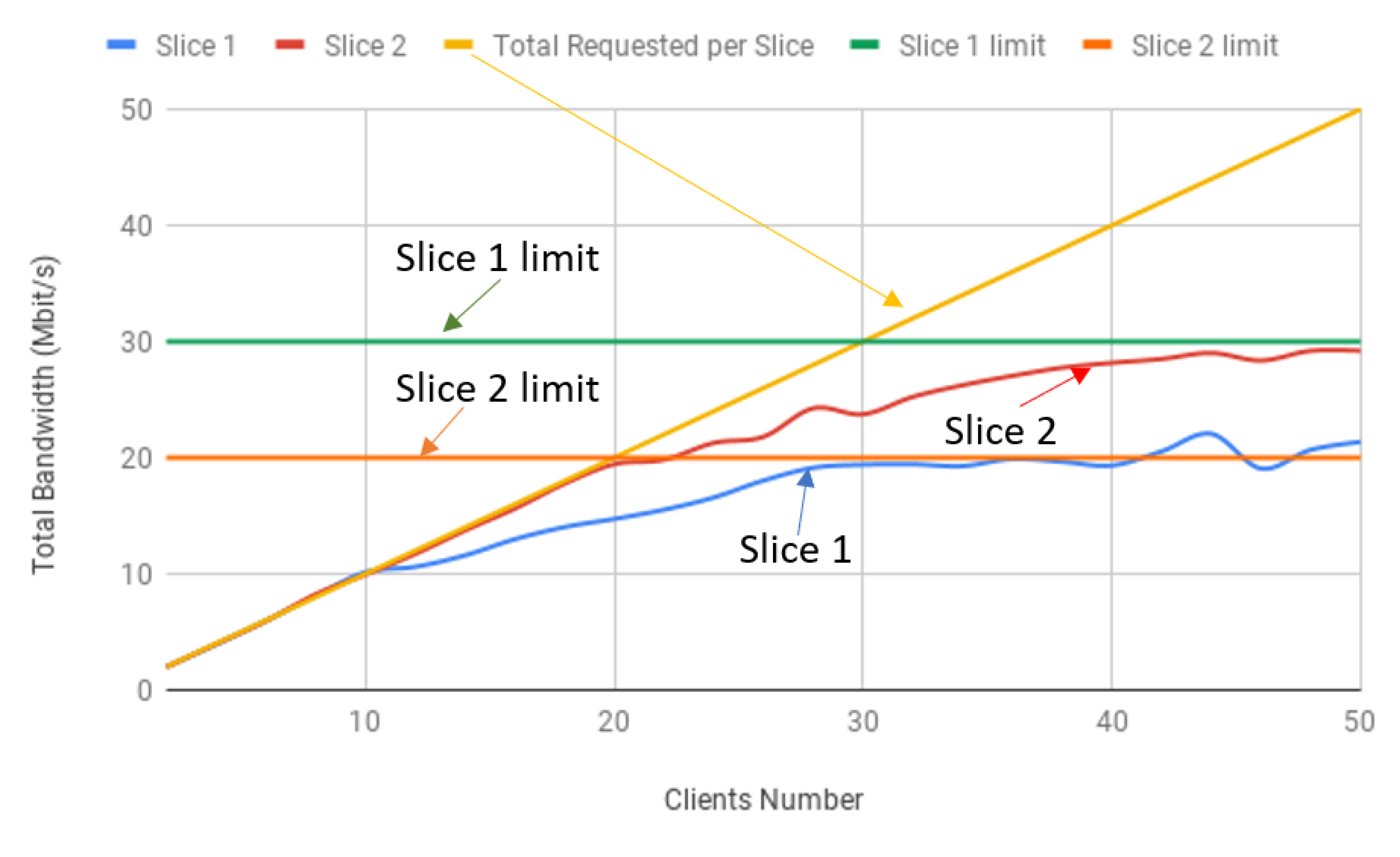
Therefore, our solution in the core switch classified traffic, applying a DSCP value based on a match of the packet transport layer protocol. Traffic that took advantage of TCP was marked with 10, while in traffic that was using UDP, a value of 18 was applied instead. Additionally, each slice switch had QoS OvS rules, specifying the queue rules to where traffic should be redirected based on OpenFlow entries that would match the known DSCP values. This means that after the core switch, the following path OvS elements did not have to deal with flows any longer, merely inspecting the packets ToS octet in order to apply QoS. The total achieved bandwidth in each slice condition is illustrated in
Figure 19, which represents the efficiency of our solution.
6. Conclusions
In this paper, we proposed, implemented and evaluated a lightweight slice-based QoS manager for non-3GPP IoT scenarios, having in mind the Industry 4.0 and digital farming use cases with specific QoS requirements. Our solution was implemented as a component in SOFTWAY4IoT considering the best effort, traffic policing, IntServ and DiffServ QoS models. The validation and evaluation were carried out in a real experimental environment. The results obtained showed that our solution has great potential for IoT deployments, which can provide the desired bandwidth for each slice (as virtual network partitions) according to the QoS requirements defined for each use case.
Our solution, as a proof of concept, is feasible, and we can go further mainly in the evolution of the solution, as well as the development of an API to automate the process.
As future work, besides the evolution of the slice-based QoS management, we are looking to deploy it as a pilot on a new version of the SOFTWAY4IoT, considering multiple gateways, centralised management and orchestration. We are working on the integration of IoT non-3GPP network access to the 5G core by SOFTWAY4IoT. We also intend to evaluate our solution regarding other performance metrics as well.


