Abstract
Mechanically stabilized earth (MSE) retaining walls have become a favored substitute for traditional poured concrete walls due to their affordability, minimal site preparation needs, and practical construction advantages. However, using backfill material with too many small particles and poor drainage qualities may cause the wall to rotate and shift a lot or collapse completely, especially when water pressure is present. This study examines an MSE wall considering different variables, such as water pressure, the type of soil materials in the backfill materials, external load, and the type of analysis. To this aim, both PLAXIS V20 and SLOPE/W (GeoStudio 2019 Suite) software were employed, and after the verification, further investigations were carried out. These numerical analyses aligned with the real-world failure reported by previous researchers, departments, and companies. The findings suggest that the elevated presence of fine particles likely contributed to the wall’s excessive shift. Also, hydrostatic pressure behind a wall, especially in the rainy season, plays a crucial role in the factor of safety reduction by 45% and wall failure, which leads us to consider it an appropriate factor of safety for the MSE wall.
1. Introduction
A composite retaining structure made up of alternating layers of compacted soil and reinforcing components attached to a facing panel is known as an MSE wall [1]. The tensile and frictional contact that forms between the reinforcements and the backfill creates overall stability [2,3]. A cohesive yet flexible gravity mass that can support heavy loads and allow for considerable differential settlement without causing structural strain is produced by this interaction [4,5]. Since MSE retaining walls require less site preparation and foundation work than gravity, semi-gravity, cantilever, and counterfort systems, they decrease right-of-way demands, enable rapid construction, support sustainable practices, and remain stable. Because of this, their use has increased over the past 25 years in a variety of civil projects [6,7]. The increased shear resistance along soil–reinforcement contacts and the increased tensile strength inside the composite soil mass are the benefits of reinforcement. MSE walls employ two categories of reinforcement: extensible and inextensible. While extensible inclusions like geogrids, geotextiles, and welded wire mesh deform to levels equal to or greater than those of the surrounding soil, inextensible inclusions like steel strips and bar mats exhibit relatively slight stresses at failure when compared to the backfill.
These walls are capable of tolerating significant differential settlement without damage and can also endure heavy loads (such as bridge abutment footings and crane loads) while offering strong resistance to seismic and accidental forces. These walls also play a key role in preventing the erosion of the backfill material and create a stable and flexible gravity system capable of withstanding various heavy loads [8]. Compared to conventional reinforced concrete (RC) retaining walls, MSE walls are a popular choice in earth retaining systems due to their economic advantages and high capacity to withstand differential settlements. Based on the particular application, wall height, and soil conditions, different types of reinforcements and MSE wall facings are employed [9]. Extensive research on MSE retaining walls, through rigorous experimentation, field investigations, analytical modeling, and numerical simulations, demonstrates that multi-tiered configurations outperform rectangular tall walls. This is particularly true for high-rise MSE retaining walls, where stability, cost-effectiveness, and aesthetic considerations are critical. The results obtained from limited examinations on multi-tiered reinforced soil walls employing numerical simulations obviously indicate that a tall MSE wall’s performance can be remarkably enhanced by its construction in a tiered manner [10,11,12,13,14].
Researchers’ understanding of MSE wall behavior has improved in the light of numerical analytical technique developments based on finite element, finite difference, and limit equilibrium schemes [15,16,17]. Programs like FLAC, MSEW, ReSSA, and PLAXIS are frequently utilized. The effects of shape, material characteristics, and stress on wall performance have been the subject of several parametric studies using these tools [18,19,20]. In order to investigate stress distributions and overall stability, Kniss et al. [21] integrated UTEXAS4 limit equilibrium analysis with PLAXIS finite element modeling. They specifically looked at how the wall aspect ratio affected both vertical and horizontal stresses, as well as safety factors related to soil shear strength and capacity. In order to determine the reinforcement length, Bilgin et al. [22] looked into the controlling failure process and assessed if the standard minimum length might be shortened. The size of the surcharge, wall height, backfill qualities, reinforcing spacing, and foundation properties were among the variables examined. In contrast to the commonly accepted figure of 0.7 times the wall height recommended by various organizations, the results showed that the necessary reinforcement length is determined by either internal or external stability and that lengths near half of the wall height may be enough.
To examine the failure mechanisms of MSE walls, field experiments, whether conducted at full scale or in proportional experiments, play a pivotal role [23,24,25,26,27]. By gauging the wall strain and pressure in field experiments, the relationship among earth pressure behind the wall, wall deflection, the secondary geogrid, and wall height can be acquired [23,24]. It has been demonstrated that secondary reinforcement significantly reduces wall-facing deflection while causing a uniform distribution of lateral earth pressure [27]. Yazdandoust and Ghalandarzadeh [25] employed scaled shaking table experiments to analyze reinforced wall failure modes, indicating the impact of nonuniform acceleration distribution on the seismic coefficient of reinforced soil structures. Safaee et al. [28] gauged the amounts of the critical dynamic parameters of single- and multi-layer walls under various seismic excitations. They investigated the behavior of wall stability by comparing single- and multi-layer walls. The stability analysis theory of the MSE wall provides an effective framework for investigating the failure mechanism governing the wall [27].
In recent years, the numerical analysis of MSE walls using the finite element method (FEM) has significantly increased. Kim et al. [9] carried out a case history of an MSE wall failure, as well as finite element modeling results and a failure mechanism assessment. They performed parametric analyses for the existing and ultimate loading conditions to aid in creating remedial actions to stem any prospective failure of the MSE wall. They concluded that as a result of significant differential settlement occurring between the wall panels supported by caissons and the reinforcement strips positioned posterior to the panels, the peak tensile stresses experienced by the reinforcement strips escalated by more than a factor of six, ultimately achieving their ultimate strength.
Hedjazi [29] conducted a finite element analysis of MSE walls by employing welded wire wall panels. The obtained results have been utilized to substantiate the feasibility of employing 3D panels as facings for MSE walls, to identify the failure modes of these panels, and to develop an adequate anchorage system. Alimohammadi and Memon [30] conducted an examination of the structural failure of an MSE retaining wall located in Tennessee, USA. They articulated a series of recommendations for the design and construction of prospective retaining walls under analogous geotechnical circumstances.
2. Research Significance and Methodology
Mechanically stabilized earth walls support highways, bridges, rail lines, and urban corridors because their compacted granular backfill, held by metallic or geosynthetic reinforcement, offers high strength with shorter construction times and a lower cost than cast-in-place concrete systems. More than eight million square meters of facing panels are installed each year across the United States, so any loss of stability would jeopardize public safety and strain transportation budgets. In the U.S.A., over 8 million square meters of MSE walls are constructed annually for highway and bridge projects, making them one of the most important constructions. Because they may save up to 30% on construction costs when compared to regular concrete barriers, they make up about half of the retaining walls utilized in federal and state transportation efforts. These walls’ reinforced construction allows for endurance in 90% of seismically active areas, supporting vital infrastructure such as roadways, railroads, and urban transportation networks. By reducing project timelines by up to 25%, MSE walls facilitate the faster delivery of transportation networks, ensuring safe and sustainable connectivity across diverse terrains. This study therefore investigates sliding and overturning performance through a clearly defined modeling–verification–evaluation sequence carried out in both PLAXIS and SLOPEW.
The two-dimensional plane strain representation of the wall described in this manuscript was built in PLAXIS and duplicated in SLOPEW. Construction was simulated in successive stages that mirror the field placement of the backfill and reinforcement. The soil was treated with a Mohr–Coulomb constitutive model, and each reinforcement layer was represented by axial elements assigned the tensile stiffness measured for the chosen metal strips or geosynthetic sheets. This study focuses on the material and loading parameters already reported earlier in this manuscript. Each parameter was varied one at a time within the project-specific ranges, while all other inputs remained fixed. This approach isolates the direct influence of every variable on sliding and overturning resistance. The numerical framework was first verified by reproducing the published factors of safety from peer-reviewed studies that employ the same backfill type and reinforcement materials referenced in this manuscript. The computed sliding and overturning factors of safety closely matched those of the benchmark values, confirming the adequacy of the adopted soil model, boundary placement, and staged construction procedure. Parallel calculations in SLOPEW yielded factors of safety that agree with the PLAXIS results, which reinforces the reliability of the dual-platform approach. After validation, the parameter study revealed that reinforcement length and backfill shear strength exert the greatest control on both sliding and overturning safety, followed by surcharge magnitude. All the findings are synthesized in Figure 1, which traces the full workflow from model definition through verification to variable-by-variable evaluation.
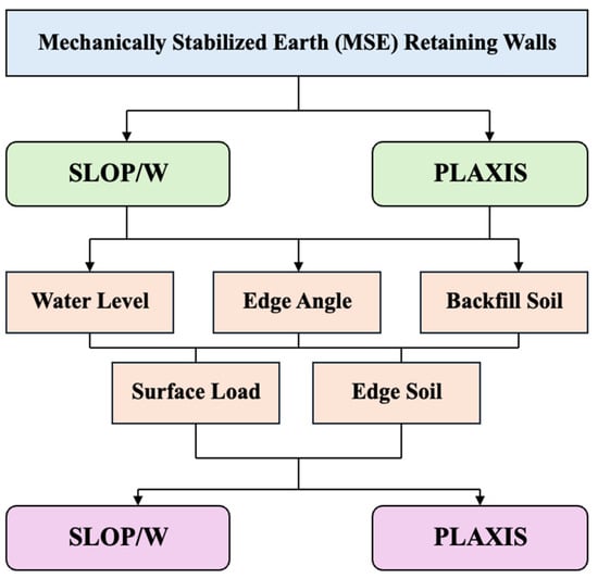
Figure 1.
Schematic presentation of this study’s methodology.
3. Verification
To validate the accuracy of the performed analysis and results, the study performed by Yu et al. [31] was used. According to their study, to validate the numerical model developed for this study, a reference case from a 6 m high mechanically stabilized earth (MSE) test wall constructed by the Public Works Research Institute of Japan in 1978 was analyzed, as shown in Figure 2 [31]. The numerical modeling and analysis of the MSE wall are carried out using the 2-D FE programmer PLAXIS. Using points, lines, and other XY-plane elements, a 2-D geometry model is produced. The properties of the materials and the boundary conditions are defined, and then an FE mesh is built to carry out an FE analysis using PLAXIS. Water pressures and effective stresses are generated as the final step in the input process, which establishes the initial state. In their paper, the FE model uses plain strain type analysis. For shapes having uniform cross sections, the plain strain model is usually used. It is assumed that there are no strains or displacements in the z-direction. However, normal stress acting in the z-direction is considered in the analysis. In PLAXIS, 15 noded triangle elements were added during modeling for the better accuracy of the calculation of stress and deformations at each point. All the variables and parameters were used as defined by Yu et al. [31]. The wall featured cruciform-shaped concrete panels, each 1.5 m high and 180 mm thick, with silty sand as the backfill material. The wall incorporated a 0.3 m wide, 0.15 m thick concrete leveling pad and 0.02 m thick bearing pads at the panel joints to prevent contact, modeled as beam elements with free rotation. The soil properties for the backfill and foundation were not specified in the original documentation, so assumed values were adopted, prioritizing the elastic modulus (10–50 MPa for backfill, 10–100 MPa for foundation) over strength parameters, as the analysis targeted operational conditions rather than failure [31]. The properties of the model are provided in Table 1 and Table 2. A linear-elastic Mohr–Coulomb model was employed with reduced stiffness (0.5 times the backfill modulus) within one meter of the facing to reflect lighter compaction practices. The backfill-facing interface was modeled with a strength reduction factor of 0.67, yielding an interface friction angle of 32.91° and adhesion of 0.67 kPa. It should be noted that in the numerical simulation using PLAXIS, the interaction between the reinforcement strips and the surrounding soil was modeled using interface elements. The properties of the soil–strip interface were defined using a reduced friction angle (ϕ) and adhesion (c) based on a strength reduction factor. Specifically, a friction angle of 32.91° and adhesion of 0.67 kPa, as reported in Table 2, were used. These values reflect realistic shear behavior at the soil–reinforcement interface. Numerical simulations using PLAXIS software accurately replicated the wall’s geometry and material properties, with strip elements representing the steel reinforcement. The model’s construction sequence mirrored the physical process, activating panels, backfill layers, and reinforcement iteratively to achieve equilibrium. By comparing the simulated reinforcement and toe loads with the measured data from the test wall, the model demonstrated a reliable prediction of structural behavior under working stress conditions, confirming its suitability for analyzing MSE wall performance in transportation infrastructure applications. Therefore, the comparison between the existing study and the benchmark model presented by Yu et al. [31] is presented in Figure 3. According to this figure, there is a high agreement between the results, and the presented models and results in this study are acceptable.
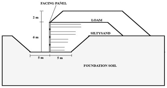
Figure 2.
Benchmark structure presented [31].

Table 1.
Properties used in verification model [31].
Table 2.
Properties of interface and strip.
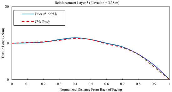
Figure 3.
Comparison between this study and Yu et al. [28] for verification.
4. Results and Discussion
After the verification, the effect of various variables were studied, and the results are provided. Figure 4 represents the soil layers and the basic structural configuration considered in this study. According to this figure, the MSE wall is supported by a soil layer named MSE that is stabilized with an edge soil layer. The whole structure is considered over a fat clay soil layer supported by underneath shale soil. The soil properties are provided in Table 3.
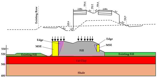
Figure 4.
General soil layers and structural configuration.
Table 3.
Material properties.
Because of its affordability, adaptability, and resilience to a range of geotechnical difficulties, MSE walls have emerged as the go-to option for retaining wall applications. However, hydrostatic pressure accumulation behind the wall, especially during periods of heavy rain, can have a substantial impact on its function. The wall structure may distort, become unstable, or even fail as a result of excessive water penetration into the reinforced backfill material, which increases lateral pressure. In order to guarantee long-term stability, this work attempts to present a thorough examination of the effects of hydrostatic pressure on MSE walls. MSE walls are based on earth structures that have been strengthened, usually using metallic or geosynthetic reinforcements. These reinforcements efficiently preserve the soil mass’s structural integrity in arid environments. However, during intense rainstorms, water may collect behind the wall due to inadequate drainage or a lack of readily draining backfill material, increasing the hydrostatic pressure over the wall’s design limit. By acting as an external force pressing on the retaining wall, this additional pressure raises lateral ground pressures and may cause the structure to collapse, bulge, tilt, or move outward.
Hydrostatic pressure has a variety of technical consequences on MSE walls. First of all, the forces acting on the reinforcing layers are amplified by increased lateral ground pressure brought on by water accumulation, frequently beyond their design limitations. Shear strength, which can be considerably diminished in saturated circumstances, is a critical component of the stability of the reinforced soil. Water degrades the granular soil structure’s interlocking qualities and reduces effective stress when it seeps into the backfill material, increasing the soil’s vulnerability to movement or deformation. Furthermore, when too much moisture weakens the bond between soil particles and reinforcement layers, reinforcing components may lose their tensile strength and their capability to offer sufficient stability. Therefore, the hydrostatic pressure behind MSE walls presents a significant engineering challenge, particularly during rainfall events. The effects of water infiltration include increased lateral earth pressure, reduced shear strength, the loss of reinforcement efficiency, erosion, and potential global instability. To this aim, in this part of this study, the effect of the water table level behind the MSE walls is studied, as shown in Figure 5. Considering the effect of the water table level, the effect of hydrostatic pressure on the sliding and overturning factor of the safety of MSE walls is provided in Table 4. Additionally, Figure 6 presents the maximum top-of-wall movement as a result of increasing the water pressure behind the wall.
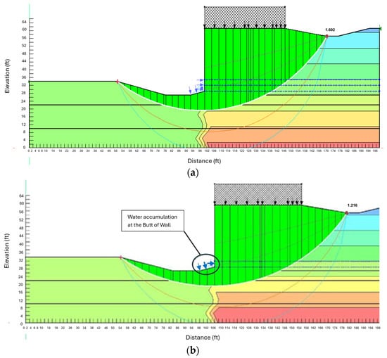

Figure 5.
Effect of water table level behind wall on sliding stability at (a) 6 ft, (b) 10 ft, and (c) 14 ft from base of wall. (Colors indicate the hydro pressure of ground water level).
Table 4.
Effect of water table level on factor of safety of MSE wall.
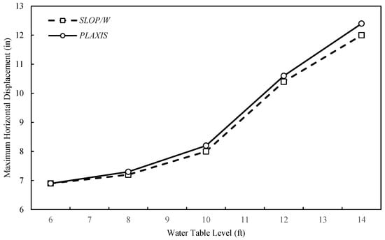
Figure 6.
Effect of water table level on horizontal displacement of MSE wall at the top.
Table 4 indicates that for sliding SLOP/W, the factors of safety are 0.6% at 6 feet, 5.1% at 8 feet, 1.6% at 10 feet, 8.5% at 12 feet, and 1.0% at 14 feet, exceeding PLAXIS by a mean margin of 3.4%. The equivalent surpluses for overturning are 1.2%, 5.2%, 0.9%, 6.4%, and 2.9%, with an average of 3.3%. This indicates that while both pieces of software follow the same downward trend as the water table rises, SLOP/W consistently forecasts somewhat greater stability. The widening peaks at 12 feet suggest that the finite element formulation in PLAXIS captures additional deformation-induced stress redistribution and pore pressure concentration that the limit equilibrium framework in SLOP/W idealizes as uniform, resulting in more conservative estimates once the phreatic surface intersects the reinforcement layers. This pattern highlights the advantage of coupling seepage with stress deformation analysis when groundwater conditions are critical, warning designers that simplified, limited equilibrium solutions may overstate the reserve capacity when partial submergence undermines the effective stress and shear bands’ form, even though the average discrepancies stay below 4%. Therefore, using PLAXIS for comprehensive verification offers an extra safety check against optimistic limit equilibrium findings, particularly close to the 12-foot level where the safety drop is greatest for both systems.
Additionally, the results show that the combination of effective stress reduction, buoyancy effects, and changes in earth pressure distribution results in a decrease in the sliding and overturning factors of safety when the water table level behind the walls rises. The effective stress in the backfill soil is decreased when the water table rises due to an increase in pore water pressure. This can reduce the driving forces that cause instability and shear strength. Furthermore, the overturning moment is lessened by hydrostatic uplift, which lowers the soil’s net weight. Stability evaluations are impacted by the decrease in lateral forces against the wall, which is another effect of the drop in effective ground pressure. Increased water table conditions also change the way reinforcements interact with the surrounding soil mass, which can change the MSE system’s overall stability performance. The apparent disparity between the findings of PLAXIS and SLOPE/W is the result of fundamentally different computing approaches. In contrast to SLOPE/W, which depends on limit equilibrium analysis, PLAXIS uses finite element analysis (FEA) to capture precise stress redistributions, nonlinear soil behavior, and seepage effects. This results in somewhat lower factor of safety values. Because of its oversimplified approach to soil–structure interaction and pore pressure effects, the latter may overestimate stability and presume pre-defined failure surfaces. Thus, its more thorough integration of stress–strain relationships with the groundwater effect is responsible for the little decrease in the PLAXIS-calculated factor of safety. Furthermore, sliding failure occurred in the MSE, but an overturning failure was not seen as the water level rose.
Because of the basic variations in failure processes and the significance of pore water pressure in soil stability, sliding failure occurs in mechanically stabilized earth (MSE) walls as water levels rise but overturning failure does not. As the water table rises, the backfill’s stress distribution changes due to the rise in hydrostatic pressure, which lowers effective stress and, in turn, shear strength. The soil is more prone to horizontal movement as a result of this decrease in shear strength, which raises the possibility of sliding failure. The moment equilibrium between the ground pressure behind the wall and the resisting forces from the wall’s weight and reinforcing system, however, is what mostly controls overturning failure. Because of buoyancy effects and changed pore pressure, the rising water level lowers active earth pressure, which lowers the driving force that causes overturning. Significant overturning is further prevented by the strengthened soil zone and by facing the system’s weight, which essentially stays constant. By efficiently transmitting loads through tensile forces, the reinforcing layers inside the MSE wall help to preserve structural integrity by reducing the likelihood of overturning tendencies while leaving slide failures possible. The intricate relationships between the soil and reinforcement under various hydraulic circumstances are captured by the finite element approach, which enables a thorough assessment of stress redistribution and seepage effects in numerical analysis using PLAXIS. In contrast, SLOPE/W makes assumptions about the limit equilibrium that can overstate the resistive forces, which might result in marginally greater factors of safety. The disparity between these two approaches emphasizes how crucial it is to take sophisticated numerical modeling into account when evaluating stability in the face of shifting groundwater conditions.
The substantial influence of groundwater conditions on structural stability is demonstrated in Figure 6, which shows the rise in the horizontal displacement of the MSE wall brought on by rising water table levels. The displacement increased from 6.9 inches to 12.4 inches, or a rise of almost 79.7%, as the water table rose from 6 feet to 14 feet. A decrease in effective stress, which results in decreased shear strength and higher lateral deformation inside the backfill, is the cause of this significant increase in movement. Higher pore water pressure modifies the distribution of earth pressure, promoting lateral displacement tendencies and decreasing soil confinement. Furthermore, the basic variations in analytic procedures between PLAXIS and SLOPE/W are the cause of the disagreement between their results. Compared to SLOPE/W, which is based on limit equilibrium assumptions, PLAXIS predicts somewhat larger displacement values because it uses finite element analysis to more thoroughly account for stress redistribution and seepage effects.
Furthermore, Figure 6 demonstrates that while both programs forecast relatively comparable wall movements at a water table of 6 feet, with the greatest horizontal displacement occurring close to 6.9 inches, PLAXIS starts to outperform SLOP/W as the water level increases. PLAXIS provides around 7.3 inches at 8 feet, whereas SLOP/W provides 7.2 inches, a 1.4% improvement. At 10 feet, the difference increases to 2.5% when PLAXIS records 8.2 inches vs. 8.0 inches. It then somewhat narrows to 1.0% at 12 feet, with values of about 10.6 inches and 10.5 inches, respectively, before expanding to 5.0% at 14 feet when PLAXIS predicts 12.6 inches and SLOP/W 12.0 inches. PLAXIS displacements are typically 2.1% greater. The abrupt slope between 10 and 12 feet shows that the water table has crossed the reinforced zone where less confinement speeds up movement, and the common upward curve reveals that greater groundwater decreases effective stress and stiffness, encouraging bigger lateral deformation. Because PLAXIS’s finite element formulation accounts for strain localization, progressive yielding, and reinforcement bending—all of which the limit equilibrium approach in SLOP/W treats as rigid body translation—it consistently produces larger offsets. As pore pressure increases, the finite element model records additional softening. Even though the mean difference is small, the 5% divergence at the highest water table indicates that any time flood or seasonal factors threaten to elevate groundwater over about 12 feet, planners should confirm limit equilibrium serviceability predictions using a deformation-based approach.
In order to prevent excessive lateral movement under various hydrogeological circumstances, effective drainage techniques and reinforcing strategies are essential, as the observed displacement increase highlights the need to take groundwater impacts into account when designing MSE walls. According to the presented results above, the water level and hydrostatic pressure behind MSE walls play a crucial role in their stability. In addition to water level, the soil properties behind the walls represents another important factor. In this regard, the MSE soil part and edge are the most important parts since they provide the reinforcement and connection to the backfill soil, respectively. In addition, backfill soil is another important part since it is directly in contact with the external surface load and, using soil strength, could transfer more stress and deformation to the wall, which could result in significant wall movement and failure. Therefore, in this section, the effect of soil properties in addition to hydrostatic pressure is studied. The results are provided in Table 5 and Table 6.
Table 5.
Simultaneous effect of water pressure and the modulus of elasticity of the fill soil.
Table 6.
Simultaneous effect of water pressure and the modulus of elasticity of the reinforced MSE and edge soils.
The results obtained indicate that the interplay of hydrodynamic pressures and soil stiffness is responsible for the observed decrease in the sliding S.F. caused by a simultaneous increase in water level from 2 feet to 8 feet and a decrease in the modulus of elasticity of the backfill soil, MSE reinforced soil, and edge soil. The rise in water level significantly increases the pore water pressure in the soil, lowering the effective stress and therefore the soil’s shear strength along the sliding plane. This impact causes increased deformation and reduced resistance to sliding forces, which are made worse by a drop in the modulus of elasticity, a sign of weakened soil. Stability is mostly dependent on the backfill soil, which usually has a bigger volume and directly supports the weight of the building. The greater settlement and lateral deformation brought on by a decrease in its modulus of elasticity destabilize the MSE structure by dispersing loads and decreasing frictional resistance at the base, which lower the sliding S.F.
Since the backfill soil plays a major role in load distribution and stress transmission within the MSE system, the effect of lowering the modulus of elasticity is more noticeable on it than on the MSE reinforced and edge soils. The stiffness of the backfill soil controls the entire structural response to external stresses, particularly those brought on by high water levels, and it has direct interactions with the foundation and reinforcing components. On the other hand, the edge soil, which is frequently found around the perimeter, has a lesser effect on the core stability mechanisms, and the MSE reinforced soil, although essential for tensile reinforcement, adds little to the system’s total stiffness. As a result, lowering the stiffness of the backfill soil causes a more substantial disturbance to the structure’s balance, which lowers the sliding FOS. These results highlight how crucial it is to choose backfill materials with sufficient stiffness and put in place efficient drainage systems in order to reduce the accumulation of pore pressure in MSE structures under various hydraulic circumstances. The failure surface in the present backfill soil modulus of elasticity is shown in Figure 7.
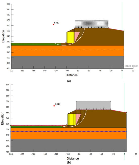
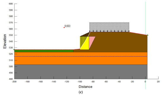
Figure 7.
Simultaneous influence of soil modulus of elasticity and water level on sliding factor of safety of (a) backfill with 2 ft water and 600 × 103, (b) backfill with 8 ft and 600 × 102, and (c) MSE and edge soils with 8 ft water and 0.5 × 10⁴.
Consequently, the relative mechanical characteristics and functions of different soil zones inside the structure may be used to explain the finding that the failure surface goes through the backfill soil rather than the MSE reinforced soil or edge soil. Usually a granular substance, the backfill soil is more prone to shear deformation in situations with higher stress, like high water levels. The backfill becomes the weakest link along the possible failure plane as a result of the increase in pore water pressure brought on by water level, which also lowers the backfill’s effective stress and shear strength. However, MSE reinforced soil exhibits enhanced shear resistance when paired with tensile reinforcement elements like geogrids or geotextiles. This is because the soil and reinforcement work together to effectively stop the development of failure planes. In a similar vein, edge soil, which is frequently compacted and found on the outskirts, does not reach the failure surface as it is less important to overall stability and encounters smaller stress concentrations. Because of the backfill soil’s decreased stiffness and shear strength when saturated, the failure surface will naturally choose the route of least resistance, which in this instance is through it.
Maintaining the structural integrity and long-term performance of MSE structures depends on the prevention of the creation of a failure surface through the MSE reinforced and edge soils. Through the interplay of soil and reinforcement, the reinforced soil zone is intended to disperse loads and avoid localized failures while providing tensile strength and stability. Because of the loss of tensile capacity, a failure surface that passes through this area would undermine the effectiveness of the reinforcement and cause a catastrophic collapse. Similarly, even though the edge soil is less important, its stability is crucial for preserving the geometry of the building and avoiding sloughing or erosion at the edges, which might make instability worse. The reinforced zone can continue to operate as planned and the edge soil can continue to play its protective role by making sure the failure surface is contained inside the backfill soil. This emphasizes how crucial it is to choose premium backfill materials with sufficient stiffness and shear strength, put in place reliable drainage systems to reduce pore pressure accumulation, and carefully plan the reinforced zone to increase composite strength in order to reduce failure risk and guarantee the longevity of MSE structures in challenging hydraulic circumstances.
Furthermore, the altered mechanical behavior of the soil–reinforcement system under these conditions can explain the observation that the failure surface passes through the MSE reinforced layer and significantly reduces the sliding S.F. when the modulus of elasticity of the MSE reinforced and edge soils are reduced in conjunction with an increase in water level. The MSE reinforced soil’s stiffness is reduced when its modulus of elasticity drops, which lessens the composite strength that the soil’s interaction with tensile reinforcement components—like geogrids and geotextiles—provides. This weakened reinforced zone is more vulnerable to failure plane propagation since it can no longer withstand shear loads as well. At the same time, the higher water level causes pore water pressure to rise, which lowers the edge and reinforced soils’ effective stress and shear strength. Because of its decreased stiffness, the edge soil usually found at the periphery may also become less stable, which may lead to stress redistribution, putting additional strain on the reinforced layer. Because it becomes the path of least resistance, the failure surface moves from the backfill soil to the MSE reinforced layer. The combined impacts of decreased soil stiffness and increasing hydrodynamic pressures, which destabilize the whole MSE system, worsen the weakened shear resistance along this new plane failure, as seen by the notable fall in the sliding S.F.
Several tactics may be used to lessen these problems and improve the stability of MSE constructions under certain circumstances. First, the stiffness and shear strength of the reinforced zone may be increased, decreasing the possibility of failure plane propagation through it, by using premium MSE reinforced soil with a higher modulus of elasticity and making sure it is well compacted. Second, adding sturdy drainage systems, like recomposite drains or perforated pipes, can efficiently control the accumulation of pore water pressure, preserving greater effective stresses and shear strength even at high water levels. Third, the structure can be further stabilized by improving the composite strength and load distribution by lengthening the reinforcing components or increasing their density and tensile strength inside the MSE layer. Peripheral instabilities that might put stress on the reinforced zone can also be avoided by routinely checking and maintaining the edge soil’s compaction and erosion resistance. Lastly, a greater sliding S.F. may be guaranteed by performing site-specific geotechnical assessments to improve the design of the soil and reinforcement characteristics under expected hydraulic conditions, improving the long-term durability and safety of the MSE structures. Figure 8, Figure 9 and Figure 10 show the stress distribution for two stable and failed cases.
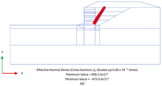
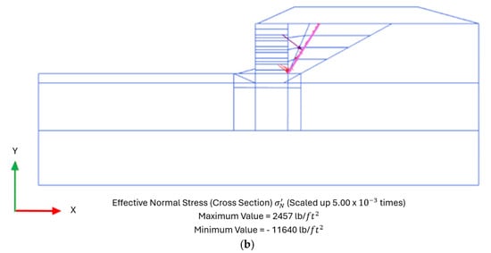
Figure 8.
Effective normal stress distribution in a (a) failed case and (b) stable case.
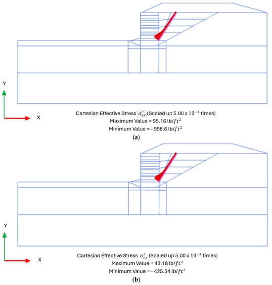
Figure 9.
Horizontal stress distribution in a (a) failed case and (b) stable case.
Figure 10.
Maximum displacement and stress distribution in a (a) failed case and (b) stable case.
In addition to the soil materials and water table levels explained above, the effect of external load was evaluated. The results are presented in Figure 11 and Figure 12. Figure 11 shows that the extra stress placed on the reinforced soil system and the ensuing redistribution of forces are the main factors influencing the observed decline in the sliding and overturning factors of safety with increasing surcharge on the MSE wall. Greater horizontal stresses and higher shear forces along possible failure surfaces result from the increased surcharge load amplifying the driving forces operating inside the backfill. As a result of the increased lateral stress challenging the reinforced soil mass’s resisting shear strength, the sliding factor of safety is significantly reduced. On the other hand, because of the nature of overturning failure mechanics, the influence on the overturning factor of safety is relatively smaller. Surcharge adds to the system’s total stabilizing weight, somewhat counteracting its destabilizing effect even if it increases the driving moments acting on the wall. Furthermore, the MSE wall’s reinforcing layers give significant tensile resistance, which improves moment balance and reduces excessive overturning tendencies while providing less control over elevated sliding stresses. In order to ensure that excessive lateral displacement and stability reduction are appropriately addressed and long-term structural integrity is maintained, it is crucial to take into account surcharge load distribution and reinforcement configuration in MSE wall design. This is demonstrated by the disparity in their relative effects on sliding and overturning stability.
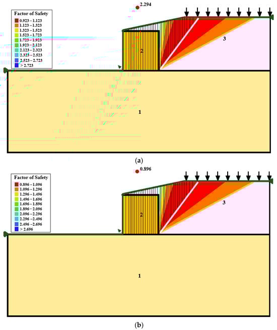
Figure 11.
Effect of surcharge load on behavior and sliding factor of safety of MSE wall at (a) 40 psf and (b) 250 psf (in This figure, area 1, 2 and 3 indicate Shale, Reinforced and Fill soils, respectively).
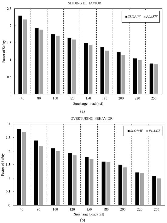
Figure 12.
Effect of surcharge load on the factor of safety for (a) sliding and (b) overturning.
Additionally, as seen in Figure 12a, the findings demonstrate a definite inverse connection between the sliding factor of safety and surcharge load, showing that the stability of the MSE wall against sliding dramatically diminishes as the applied load increases. The increased horizontal stress brought on by surcharge loads, which intensify the driving forces operating parallel to the reinforcing layers, directly results in a decrease in the sliding factor of safety. The reinforced soil system’s resisting shear strength is effectively decreased by this increase in lateral stress, hastening the decline in stability. The sliding factor of safety decreased from 2.294 at 40 psf to 0.896 at 250 psf, indicating a 60.9% total decline according to the data’s numerical trend, which is nonlinear. Higher surcharge loads cause the rate of reduction to become more noticeable, suggesting that slide resistance gradually weakens as increasing stress increases soil deformation and lowers reinforcing effectiveness. The MSE wall’s structural reinforcing layers offer tensile resistance, which prevents excessive sliding, but above a critical load threshold, the cumulative horizontal shear pressures exceed this resistance, raising serious stability issues. In order to minimize shear-induced sliding failure, the obtained findings highlight the need to optimize reinforcement designs, especially for high-surcharge scenarios where careful consideration in reinforcing strength, length, and spacing is required. In order to maintain safe and dependable structural performance under growing surface loads, this trend emphasizes the significance of surcharge control in MSE wall applications and the necessity of thorough stability evaluations. Additionally, SLOP W forecasts a bigger reserve at all loads. The margin remains small at 3.7% at 80 psf and 4.2% at 100 psf, then drops to 2.5% at 120 psf. The factors are 2.30 and 2.20 at 40 psf, meaning that SLOP W is 4.5% higher. After this, deformation starts to dominate the response that PLAXIS records, causing the gap to increase. The difference increases to 4.9% at 150 psf, reaches a peak of around 11.7% at 200 psf, and stays over 8% for the two largest loads. On average, SLOP W is 6.7% more optimistic across the nine examples. When surcharge-induced shear reaches the reinforcement layer, PLAXIS provides a more conservative estimate because the divergence at a high surcharge indicates that the finite element model can detect strain softening and reinforcement slip, which the limit equilibrium idealizes as stiff sliding.
Furthermore, the findings show that the overturning factor of safety decreases as the surcharge load increases, underscoring the impact of external loading on moment equilibrium. The overturning factor of safety decreases from 2.822 to 1.084, or a total drop of 61.6%, when the surcharge rises from 40 psf to 250 psf. The higher vertical load placed on the MSE wall system is the cause of this reduction since it increases the driving moments that cause overturning instability. The stabilizing effect of the surcharge-induced weight is seen in the somewhat lower rate of drop compared to the sliding factor of safety. Higher surcharge loads raise the overall weight of the reinforced soil system, which gives it more resistance against rotational failure even if they also increase its overturning moments. The numerical trend suggests that the accumulating surcharge-induced driving forces are increasingly challenging the resisting moment capacity, as the reduction in overturning stability is relatively moderate at lower surcharge loads and more sharply decreases beyond 150 psf. Although their efficiency is gradually reduced under situations of severe load, reinforcement layers are essential in reducing overturning tendencies because they fix the reinforced soil mass and improve overall moment resistance. In order to minimize excessive overturning instability under heavy surcharge applications, our findings highlight the need to maintain an adequate reinforcement distribution and structural weight control. Maintaining long-term MSE wall stability and reducing surcharge-induced overturning effects require careful design considerations, such as lengthening reinforcement and making sure there is enough facing integrity. Moreover, the factors are 2.80 and 2.65 at 40 psf, which represent a 5.7% surplus for SLOP W. At 80 psf, the gap increases to 10.6%, then fluctuates between around 4% and 7% from 100 psf to 220 psf, before peaking at 11.3% at 250 psf. The average advantage is over 6%. This pattern once again demonstrates that PLAXIS records more rotation and modulus deterioration in the soil and reinforcement as surcharge moments rise, which prevents the limit equilibrium from reproducing and results in lower factors.
The findings showed that when evaluating the structural integrity and performance of MSE walls, overturning behavior is a crucial consideration. The results on the impact of the water table level on the overturning moment are shown in Figure 13. This figure indicates that the overturning moment increases as the water table level behind the MSE wall rises, mostly as a result of the extra hydrostatic stresses acting on the retained soil mass. The lateral ground pressure distribution changes when the water table rises, increasing the driving force that causes overturning. The observed variations in the maximum overturning moment between water table levels of two, four, six, and eight feet, however, show that the rate of increase is not very significant. This suggests that the influence of water pressure stabilizes rather than continuously increases beyond a certain depth. This behavior is probably caused by the backfill’s internal stress redistribution and the reinforcement’s counteracting action, which keeps the system balanced against overturning forces. The pattern of the overturning factor of safety diminishing with increasing water table levels emphasizes the importance of efficient stress reduction in stability evaluation, even if the overturning moment remained over 1.0 across all water levels examined. Pore water pressure decreases the soil’s effective weight as groundwater levels increase, decreasing the resisting forces that prevent the overturning motion. As a result, the resistive moment declines more noticeably, resulting in a decreased factor of safety, even when the absolute overturning moment does not increase significantly. In order to ensure that excessive water penetration does not jeopardize the system’s capacity to maintain structural stability under a variety of hydraulic circumstances, this decrease highlights the importance of appropriate drainage systems and reinforcing design in MSE wall applications.
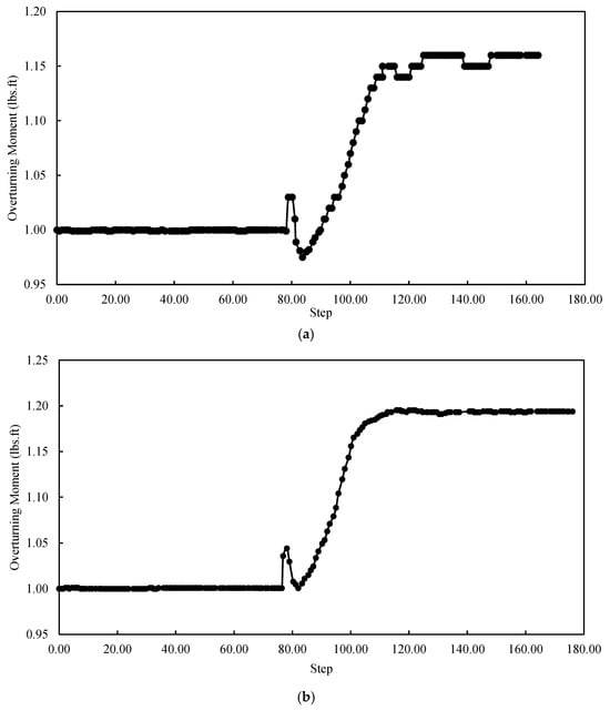
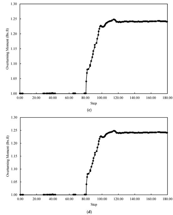
Figure 13.
Effect of water table level on overturning moment at (a) 2 ft, (b) 4 ft, (c) 6 ft, and (d) 8 ft.
5. Conclusions
With an emphasis on sliding and overturning stability, this study thoroughly examined the structural performance and stability of mechanically stabilized earth (MSE) walls under various hydraulic and loading circumstances. This study’s analysis of the impacts of soil characteristics, hydrostatic pressure, and external surcharge loads on MSE wall behavior was confirmed by comparisons with previous research using PLAXIS and SLOPE/W software. Important parameters including soil stiffness, water table levels, and surcharge loads were all thoroughly assessed to see how they affected wall displacement and stability considerations. The results demonstrate how important soil characteristics, groundwater management, and reinforcement design are to guarantee the long-term functionality of MSE walls in transportation infrastructure.
- As a result of increasing pore water pressure, which decreased effective stress and shear strength, rising water table levels dramatically decreased the sliding and overturning factors of safety. The weight of the wall and the tensile resistance of the reinforcing system reduced overturning failure, highlighting the necessity of efficient drainage to control hydrostatic pressure. Sliding failure was found to be the predominant failure mechanism.
- Compared to edge and MSE-reinforced soils, the modulus of elasticity of the backfill soil had a more noticeable impact on sliding stability. Because of its lower shear strength under saturated circumstances, failure surfaces mostly passed via the backfill, and decreased backfill stiffness resulted in higher lateral deformation and a decreased sliding factor of safety.
- The sliding (60.9%) and overturning (61.6%) factors of safety decreased nonlinearly as surcharge loads increased from 40 psf to 250 psf. While the reinforcement layers offered some resistance to overturning, increased horizontal loads had a greater detrimental effect on sliding stability, highlighting the need for an optimal reinforcement design for high-load situations.
- Using finite element analysis, PLAXIS forecasted larger displacements and marginally poorer factors of safety than SLOPE/W’s limit equilibrium method. This disparity indicates PLAXIS’s predilection for complicated hydrogeological situations by highlighting its capacity to more precisely capture seepage effects and stress redistribution.
- Because of the decreased shear strength and changed ground pressure distribution, the horizontal wall displacement increased by 79.7% (from 6.9 to 12.4 inches) when the water table rose from 6 to 14 feet. This highlights the significance of having robust drainage systems to prevent excessive lateral movement.
6. Suggestions
To improve MSE wall resistance against hydrostatic pressure, future studies should investigate cutting-edge drainage materials and layouts. Design requirements may be further raised by examining the long-term performance of innovative reinforcing materials under harsh weather and cyclic loads. Furthermore, more research is necessary to improve soil–reinforcement interactions and forecast failure surfaces by incorporating machine learning algorithms. Additionally, it is highly recommended for future investigations to implement more advanced constitutive models (e.g., Hardening Soil Model or Modified Cam-Clay) in order to obtain a better reflection of nonlinear stress–strain behavior under high pore pressure.
Author Contributions
A.K.P.: Conceptualization, methodology, software, formal analysis, investigation, writing—original draft, writing—review and editing, and visualization. A.S.: Supervision, conceptualization, methodology, and writing—review and editing. E.N.F.: Supervision, conceptualization, methodology, and writing—review and editing. All authors have read and agreed to the published version of the manuscript.
Funding
This research received no external funding.
Data Availability Statement
The data presented in this study are available on request from the corresponding author.
Conflicts of Interest
The authors declare no conflict of interest.
References
- Li, T.; Zhong, Y.; Xu, P.; Yang, G.; Jiang, G. Centrifuge model tests on performance of MSE walls with different facing types. Geotext. Geomembr. 2024, 52, 1045–1053. [Google Scholar] [CrossRef]
- Xu, P.; Zhong, Y.; Hatami, K.; Yang, K.; Liu, W.; Jiang, G. Centrifuge and limit analysis investigation of hybrid wrapped-face, full-height panel MSE walls on clay foundations. Transp. Geotech. 2024, 48, 101308. [Google Scholar] [CrossRef]
- Yünkül, K.; Gürbüz, A. Determination of shear stress-shear strain behavior of polymeric geostrip reinforced MSE wall. Geotext. Geomembr. 2024, 52, 184–195. [Google Scholar] [CrossRef]
- Zheng, Y.; Li, F.; Guo, W.; Wang, P.; Yang, G. Influence of facing conditions on the dynamic response of back-to-back MSE walls. Soil Dyn. Earthq. Eng. 2023, 164, 107650. [Google Scholar] [CrossRef]
- Xu, P.; Zhong, Y.; Hatami, K.; Yang, G.; Liu, W.; Jiang, G. Influence of reinforcement design on seismic stability of full-height panel MSE walls. Soil Dyn. Earthq. Eng. 2023, 165, 107674. [Google Scholar] [CrossRef]
- Xu, P.; Yang, G.; Hatami, K.; Li, T. Upper-bound limit analysis of MSE walls subjected to strip footing load. Geosynth. Int. 2022, 31, 54–66. [Google Scholar] [CrossRef]
- Zheng, Y.; Li, F.; Niu, X.; Yang, G. Numerical investigation of the interaction of back-to-back MSE walls. Geosynth. Int. 2022, 30, 382–397. [Google Scholar] [CrossRef]
- Bathurst, R.J. Developments in MSE wall research and design. In International Congress and Exhibition “Sustainable Civil Infrastructures”; Springer International Publishing: Cham, Switzerland, 2019; pp. 22–50. [Google Scholar]
- Kim, D.; Bhowmik, S.K.; Willmer, J.L. A case history of MSE wall failure: Finite element modeling and evaluation. In GeoFlorida 2010: Advances in Analysis, Modeling & Design; 2010; pp. 2232–2242. Available online: https://ascelibrary.org/doi/10.1061/41095%28365%29226 (accessed on 1 June 2025).
- Leshchinsky, D.; Han, J. Geosynthetic reinforced multitiered walls. J. Geotech. Geoenvironmental Eng. 2004, 130, 1225–1235. [Google Scholar] [CrossRef]
- Yoo, C.; Kim, S.B. Performance of a two-tier geosynthetic reinforced segmental retaining wall under a surcharge load: Full-scale load test and 3D finite element analysis. Geotext. Geomembr. 2008, 26, 460–472. [Google Scholar] [CrossRef]
- Liu, H.; Yang, G.; Ling, H.I. Seismic response of multi-tiered reinforced soil retaining walls. Soil Dyn. Earthq. Eng. 2014, 61, 1–12. [Google Scholar] [CrossRef]
- Bhattacharjee, A.; Amin, M.U. Behaviour of two-tiered geosynthetic-reinforced soil walls. INAE Lett. 2019, 4, 91–100. [Google Scholar] [CrossRef]
- Srivastava, A.; Chauhan, V.B. Parametric studies using finite element modeling for the evaluation of the performance of tiered MSE walls under seismic loading. Innov. Infrastruct. Solut. 2021, 6, 159. [Google Scholar] [CrossRef]
- Mohammed, W.; Han, J. Laterally-loaded pile-MSE wall system performance under different design configurations. Geosynth. Int. 2022, 29, 116–136. [Google Scholar] [CrossRef]
- Xu, P.; Hatami, K.; Yang, G.; Li, T.; Liang, X. Influence of facing toe condition on the bearing capacity of full-height panel MSE walls. Geosynth. Int. 2022, 29, 593–609. [Google Scholar] [CrossRef]
- Bhandari, P.; Sahadat Hossain, M.D.; Azijul Islam, M.D.; Badhon, F.F. Controlling base movement of MSE walls using recycled plastic pins. Transp. Geotech. 2022, 32, 100707. [Google Scholar] [CrossRef]
- Rajagopal, G.; Thiyyakkandi, S. Effect of reinforcement stiffness on response of back-to-back MSE wall upon infiltration. Geosynth. Int. 2022, 29, 409–425. [Google Scholar] [CrossRef]
- Soleimanbeigi, A.; Ozocak, A.; Li, B.; Akmaz, E.; Dayioglu, A.Y.; Tanyu, B.F.; Aydilek, A.H.; Likos, W.J. Mechanical and hydraulic compatibility of RAP with geosynthetics used in MSE walls. Geosynth. Int. 2022, 29, 1–18. [Google Scholar] [CrossRef]
- Ahmadi, H.; Bezuijen, A.; Zornberg, J.G. Interaction mechanisms in small-scale model MSE walls under the strip footing load. Geosynth. Int. 2021, 28, 238–258. [Google Scholar] [CrossRef]
- Kniss, K.T.; Wright, S.G.; Zornberg, J.G.; Yang, K.H. Design Considerations for MSE Retaining Walls Constructed in Confined Spaces; 2007. Available online: https://library.ctr.utexas.edu/ctr-publications/0-5506-1.pdf (accessed on 1 June 2025).
- Bilgin, Ö. Failure mechanisms governing reinforcement length of geogrid reinforced soil retaining walls. Eng. Struct. 2009, 31, 1967–1975. [Google Scholar] [CrossRef]
- Jiang, Y.; Han, J.; Parsons, R.L.; Brennan, J.J. Field instrumentation and evaluation of modular-block MSE walls with secondary geogrid layers. J. Geotech. Geoenvironmental Eng. 2016, 142, 05016002. [Google Scholar] [CrossRef]
- Jiang, Y.; Han, J.; Zornberg, J.; Parsons, R.L.; Leshchinsky, D.; Tanyu, B. Numerical analysis of field geosynthetic-reinforced retaining walls with secondary reinforcement. Géotechnique 2019, 69, 122–132. [Google Scholar] [CrossRef]
- Yazdandoust, M.; Ghalandarzadeh, A. Pseudo-static coefficient in reinforced soil structures. Int. J. Phys. Model. Geotech. 2020, 20, 320–337. [Google Scholar] [CrossRef]
- Razeghi, H.R.; Viswanadham, B.V.S.; Mamaghanian, J. Centrifuge and numerical model studies on the behaviour of geo-friendly reinforced soil walls with marginal backfills with and without geocomposite layers. Geotext. Geomembr. 2019, 47, 671–684. [Google Scholar] [CrossRef]
- Li, J.; Li, X.; Jing, M.; Pang, R. Numerical limit analysis of the stability of reinforced retaining walls with the strength reduction method. Water 2022, 14, 2319. [Google Scholar] [CrossRef]
- Safaee, A.M.; Mahboubi, A.; Noorzad, A. Experimental investigation on the performance of multi-tiered geogrid mechanically stabilized earth (MSE) walls with wrap-around facing subjected to earthquake loading. Geotext. Geomembr. 2021, 49, 130–145. [Google Scholar] [CrossRef]
- Hedjazi, S.; Solan, D. Finite element modeling of mechanically stabilized earth walls built with welded wire wall panels. Proc. Int. Struct. Eng. Constr. 2020, 7, 1–6. [Google Scholar] [CrossRef]
- Alimohammadi, H.; Memon, A.A. Case Study of Mechanically Stabilized Earth (MSE) Retaining Wall Failure in the State of Tennessee; Recommendations for Future Design and Constructions. J. Civ. Eng. Res. 2023, 5, 52–65. [Google Scholar] [CrossRef]
- Yu, Y.; Bathursta, R.J.; Miyata, Y. Numerical analysis of a mechanically stabilized earth wall reinforced with steel strips. Soils Found. 2015, 55, 536–547. [Google Scholar] [CrossRef]
Disclaimer/Publisher’s Note: The statements, opinions and data contained in all publications are solely those of the individual author(s) and contributor(s) and not of MDPI and/or the editor(s). MDPI and/or the editor(s) disclaim responsibility for any injury to people or property resulting from any ideas, methods, instructions or products referred to in the content. |
© 2025 by the authors. Licensee MDPI, Basel, Switzerland. This article is an open access article distributed under the terms and conditions of the Creative Commons Attribution (CC BY) license (https://creativecommons.org/licenses/by/4.0/).