1. Introduction
Poultry farming has undergone severe transformations in recent decades due to technological innovations promoted by Precision Animal Science [
1,
2]. Concerns such as loss reduction, environmental analysis, behavioral analysis and animal welfare are factors that drive the use of technologies such as Big Data [
3], Artificial Intelligence [
4,
5,
6,
7] and robotics [
8,
9] as solutions for identifying technological bottlenecks in production rates. This allows the understanding of how some production gaps can be filled through the combination of electronic devices with intelligent technologies that generate analytical and predictive models on animal production points that are not easy to analyze.
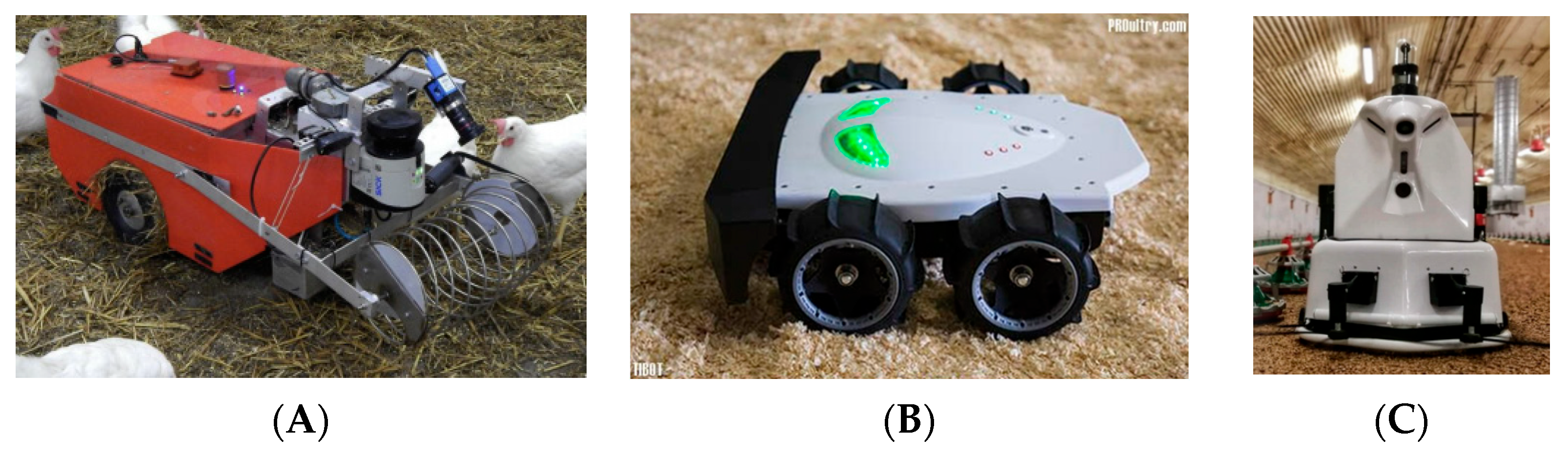
Robotics enters this context as a tool that can be used both to monitor and to act in so-called “smart farms”. In performance, repetitive tasks (those that require human presence in unhealthy situations/hazardous) can be automated by a mechanical and electronic device that executes such tasks according to a previously programmed result. Current research presents several robots that have the ability to collect eggs from the floor of the aviary (
Figure 1A) [
10,
11], turn over the litter (
Figure 1B), sanitize the environment and promote the movement of birds (
Figure 1C) [
12,
13,
14]. In monitoring, high-precision environmental sensors are used to evaluate thermal and environmental conditions that are fundamentally required for the physiological development of animals and to promote very good welfare [
4,
15,
16], as well as to activate equipment.
In poultry farming, environmental monitoring relies on two main types of equipment: stationary machines and mobile robots. Fixed-location monitoring systems use sensors and cameras to provide continuous surveillance of specific areas, such as entrances, perimeters, and critical points. These systems often integrate with alarms, ensuring consistent security coverage. Mobile monitoring robots, on the other hand, adaptively navigate different environments, making them better suited for large or dynamic spaces. Their flexibility allows for route adjustments and task reprogramming. However, their mobility increases maintenance needs and energy consumption, which can affect operational efficiency. Both solutions benefit from AI and machine learning, enabling predictive behavior analysis and real-time automation to enhance monitoring precision and adaptability [
20,
21,
22].
Navigating a robot in an aviary presents significant challenges due to the dynamic and unpredictable nature of the animals’ environment. To mitigate disturbances, specialized autonomous movement algorithms are required to ensure smooth and non-intrusive path planning. Some systems utilize proprietary Directed Coverage Path Planning (DCPP) algorithms [
23], while others adopt open-source solutions like A* (A-star) [
24]. Most implementations integrate hardware, such as LiDAR sensors, with software, including computer vision, to develop proprietary autonomous navigation systems [
25]. Effective robotic navigation in such dynamic settings thus depends on scenario-specific algorithm models, leveraging integrated technologies for optimal performance [
20,
26,
27].
This study presents the hypothesis that it is possible to use rapid prototyping mechanical and electronic components to develop a mobile robot to apply in poultry farming. The objective of the study was to develop and validate a robotic prototype (RobôFrango) for poultry farming, focusing on selecting and testing the most suitable components for broiler production systems. The specific objectives were (a) to design and implement a robotic structure (so-called RobôFrango) capable of supporting electronic components for movement and data collection; (b) to develop and implement an algorithmic structure in a compatible programming language capable of performing the locomotion and actuation of the robotic structure in a commercial broiler poultry farm; and (c) to carry out the execution of this robotic structure in a commercial poultry farm to evaluate its efficiency in movement.
2. Materials and Methods
The present study follows a development-based research approach focused on technological evolution and iterative prototyping. Therefore, the structure of the manuscript intentionally adopts a chronological narrative, detailing the evolution of the robotic prototypes from initial design stages to the final solution. This structure is commonly employed in engineering and applied robotics studies [
28,
29] where the primary objective is the stepwise resolution of technical challenges rather than a conventional experimental hypothesis testing framework. This narrative approach allows the reader to follow the decision-making process, the identification of technological bottlenecks, and the improvements implemented at each iteration, which are fundamental outcomes in robotics development studies.
The construction technique was adapted into the Scrum software 2020 development methodology [
30]. It was proposed to prepare a “product backlog” for the project’s functionalities and then “sprint backlogs” were defined with a maximum execution time of 3–5 weeks, totaling a perspective of 15 months of development. The construction was divided into 3 “sprints” (
Figure 2).
The details of the “sprints” are presented below:
Sprint 1 (evolutionary prototypes): identification of the most suitable electronic components for the project and their behavior in a commercial broiler aviary. This “sprint” generated several prototypes of robotic structures that were analyzed on different aspects (locomotion, load capacity, data reading, etc.); the results were several qualitative perspectives on the use of components until the adaptation of the most suitable ones for building the model and subsequent final product.
Sprint 2 (3D modeling and physical implementation): Design of the structural dimensioning of the robotic composition was carried out through modeling using a CAD (Computer-Aided Design) tool. The objective was to develop a virtual prototype that could be validated in a reduced scale format and dimensions in order to accommodate all components and their distribution to harmonize with the robot’s center of gravity; the final model was built in real size using structuring materials.
Sprint 3 (coding and field experiment): implementation of an algorithm in a programming language that allowed (a) manipulating the robot’s locomotion motor structure and (b) moving it around the aviary to analyze the electronic and mechanical components.
It is important to clarify that this study is focused on the technological development process of a robotic platform for poultry farming using an evolutionary prototyping approach. The objective was not to perform a statistical comparison between prototypes or to quantify the aging of mechanical and electronic components, such as wheel degradation or chemical wear. Each prototype iteration served as an engineering step to identify and solve specific design challenges related to locomotion, stability, battery autonomy, and structural adequacy under poultry house conditions. Therefore, detailed statistical analyses regarding component lifespan, debris accumulation, or physical–chemical aging were beyond the scope of this study but are acknowledged as relevant topics for future research.
It is important to note that the field tests were conducted using a single functional prototype, as it is the standard in engineering design research. To ensure repeatability and reliability of the locomotion performance assessment, three independent movement trials were performed for each motor configuration, both under unloaded and loaded conditions (with a 2.5 kg additional weight simulating the environmental sensor module). This approach is consistent with robotics validation protocols in agricultural applications [
30,
31], where replication occurs at the level of test runs rather than multiple physical prototypes.
This study was submitted, analyzed and approved by the Ethics Committee on the Use of Animals of the Luiz de Queiroz College of Agriculture of the University of São Paulo under protocol number 7364090322. To carry out this project, a partnership was established with a broiler chicken producer of the Cobb lineage, located in the city of Itatiba, in the state of São Paulo (latitude: −23.0068; longitude: −46.8387; 23°0′24″ S, 46°50′19″ W; altitude: 771 m). The region is characterized by a humid subtropical climate, classified as Cfa according to the Köppen–Geiger system. The aviary used was a negative pressure type, measuring 135 m in length, 14 m in width, and 3 m in ceiling height. It was equipped with evaporative cooling pads, exhaust fans, and an automatic electronic system for monitoring relative humidity and dry air temperature (inoBram brand, model SMAAI 3 PE, Pato Branco, Brazil).
3. Results and Discussion
3.1. Evolutionary Prototypes
The environment of poultry housing is too aggressive of a place for the presence of electronic components and circuits. Levels of gases (such as ammonia and carbon dioxide), dust, relative humidity and air temperature are always in fluctuation, which can affect the useful life of the chemical and physical components that make up electronic equipment. Furthermore, the floor (chicken litter) is another factor that makes the presence of robots difficult due to several factors; for example, its own material can make it difficult to move the wheels and the animals’ debris (droppings: feces and urine) can accumulate in the couplers, thus increasing drag and causing corrosion. Therefore, the results of preliminary studies of different types of robotic architectures, motors, batteries, microcontrollers, etc., are presented to determine which ones would be best suited for this environment.
3.1.1. First Prototype
The first prototype was built on an aluminum structure, with a Wemos D1 microcontroller, four 6 v DC motors, 65 mm × 25 mm wheels, an L298N H bridge and three 1500 mAh 18,650 batteries (
Figure 3).
This prototype was tested on a commercial poultry farm and presented the following results: the wheels were smooth and accumulated a lot of litter, in addition to being too small to elevate the structure and maintain enough free space to avoid scraping the prototype’s floor; the motors were very weak and were unable to drive the structure (which was light, 745 g) in addition to not being able to make the robot perform curves (even braking the left wheels to turn to the right and vice versa); however, the H bridge was satisfactory for motor control (driver). The three 1500 mAh model 18,650 batteries had enough charge to carry out the tests and were later recharged; the aluminum structure did not guarantee adequate insulation, generating, from time to time, short circuits that shut down the entire structure; the microcontroller proved to be satisfactory, managing to support a program in C++ language that directed the robot. Finally, its size (length 25 cm × width 15 cm × height 12 cm) was not enough to be around the animals in the final weeks of the breeding cycle and it was unable to carry an environmental analysis module.
3.1.2. Second Prototype
The attempt to purchase a ready-made chassis (or structure) was made in the second prototyping (
Figure 4). However, the results were not satisfactory: a resistant plastic structure was acquired with the advantage of maintaining an excellent free space above the ground (8 cm) but its dimensions (length 25 cm × width 20 cm × height 10 cm) were not sufficient to load ambience sensors. Furthermore, it only provided support for the same direct current (DC) motors and wheels as the previous robot and still did not have Battery Management System (BMS) protection despite being able to support some ambience sensors; the Wemos D1 proved to be incompatible as it has only one analog port and there are several sensors that transmit data through analog ports, requiring the insertion of another component (multiplexer) to guarantee this communication in addition to its size, which took up a lot of space in the structure. Finally, the motorization did not have enough strength to turn the robot.
The fragility of the wheels led to studies that determined the best type to be used on chicken litter (specifically sawdust and peanut shells). Five types of wheels were analyzed and the fitting hole between the wheel and the motor was not considered (there are couplers that serve as a connection between the wheel and the motor shaft) (
Table 1). The manufacturer was disregarded because this type of equipment generally does not have labeling.
Characteristic factors of the bedding (such as compaction, hardening, plastering, excess excrement, etc.) were analyzed qualitatively using the technical specifications of the wheels. Therefore, the five models used in this research were analyzed on two aspects: grip and height (free space) from the floor. The adhesion factor was chosen due to the different characteristics that the bedding presents throughout its useful life; the height factor was chosen due to the possibility of keeping the robot chassis as high as possible from the chicken litter, avoiding drag. For grip, all wheels that had smooth rubber or discreet trim (wheel 34 mm, wheel 68 mm and wheel 85 mm model B) were discarded as they tended to slip and accumulate debris easily. For height (free space), the 130 mm wheel and the 85 mm model A wheel proved to be compatible with the presence of both deformities on the bed surface (elevations and depressions) and cobbled parts. Finally, considering that the bedding can appear as compact, stony, plastered, muddy or soft (depending on its time of use and level of conservation), it was concluded that both the 85 mm and 130 mm wheels presented a good distance of free space for the robotic structure in relation to the ground, in addition to having sufficient grip to detach the robotic structure as they were rubberized with claws. However, the 130 mm wheel had a larger free span (65 mm) than the 85 mm wheel (42 mm) due to the robot’s chassis design and the later addition of a bed humidity sensor to the structure.
3.1.3. Third Prototype
The third prototype (
Figure 5) was based on the Ackerman architecture, thus having a chassis and front axle capable of steering. In this model, the Wemos D1 mini microcontroller was chosen because it is small in size and thus created space for the presence of the environmental sensor module. The dimensions of this prototype were 55 cm (length) × 15 cm (width) × 10 cm (height).
The steering of the wheels was enough to make the robot move in several directions, and the size made it possible to accommodate the prototype of the environmental sensor; however, the Wemos Mini has a very small number of digital ports and only one analog one, and this model still relies on very low wheels and weak DC motors. The batteries did not have a protection circuit (Battery Management System) which resulted in their malfunction (very rapid discharges), especially when their life was at the end, but their lifespan was considered good (around 1 h uninterrupted). Its movement in the aviary was satisfactory; however, it could not support weight above 1 kg (e.g., if an animal climbed onto this prototype it would not have the strength to continue its movement).
The batteries used in this third prototype were analyzed, focusing on three types: LiPO, Li-Ion and sealed batteries (Valve-Regulated Lead–Acid—VRLA). Rather than individual cells, the analysis considered battery packs designed to provide higher energy storage capacity, with protection circuits (BMS) and voltage variations between 6 v and 16 v (minimum and maximum limits supported by the Wemos Mega R3 ESP8266/ATmega2560).
Table 2 presents the models evaluated.
The two Lipo batteries presented voltages compatible with what was needed in the project, but they have a low charge capacity. According to the study carried out by [
31] on the influence of temperature on robotic structures, the reference temperature for this type of battery is 20 °C and variations above or below 10 °C reduce its usability by around 8 to 25% (permanent). Therefore, as these batteries already have a low charge capacity and the aviary, over several weeks of breeding phases, has an ambient temperature above 30 °C, it was concluded that the temperature of the aviary would reduce the useful life of the battery and, therefore, if it had a low charging capacity, it would have a reduced useful life. Therefore, this type of battery was qualified as unsuitable for the project. The VRLA-type battery has a large charging capacity (40 Ah) and voltage compatible with the project; however, an excess weight of 13.5 kg will cause excess weight to the robotic structure, thus requiring motors with higher starting torque, due to the weight of the battery plus the robotic structure itself. This characteristic disqualified this battery, also making it incompatible with the project. The JWS Li-Ion battery pack featured a low voltage (8.4 v), a high charging capacity (28 Ah) and an adequate weight (285 g). Finally, LiitoKala’s Li-Ion battery pack had an adequate voltage (12 v), a good charging capacity (10 Ah) and also an adequate weight (412 g).
Based on these considerations, it was concluded that the JWS Li-Ion battery was compatible with the project’s need for powering the sensor circuit as it has a high charging capacity and voltage (8.4 v) equivalent to the Wemos R3 AtMega, but not compatible with 12 v DC motors. The Li-Ion battery had a compatible voltage (12 v) with 12 v DC motors and a good charging capacity. Thus, it was understood that the sensor circuit should be implemented separately from the movement circuit, ensuring compatible voltages with the components of each circuit and increasing the operating time capacity of the robotic structure. Therefore, two circuits are presented in the system (movement and sensing) with individual supplies. This corroborates what is presented in the PoultryBot power system, as according to [
30], a 12 v battery set was made available for the robot’s obstacle sensing system, with another 24 v battery for the motorization system. This was due to the fact that 24 v motors were adopted in the PoultryBot, which made the power supply system for the motorization mechanism and the sensing mechanism incompatible. In this project, voltage compatibility was guaranteed between all sensors and actuators, enabling the use of a single battery model with the same voltage.
3.1.4. Fourth Prototype
The fourth prototype (
Figure 6) presented satisfactory results in terms of movement and, therefore, was completed with a cover structure (dimensions: length 45 cm × width 45 cm and height 12 cm). At this point, the environmental sensor module was coupled, and it was possible to carry out environmental analysis tests. However, its small wheels (prone to accumulating dirt and often jamming), limited weight capacity (unable to move if an animal climbed on it), low ground clearance (which caused frequent scraping on uneven surfaces), and excessive width made it unsuitable for the environment, mainly because it was unable to fend off animals (this was suggested by escape distance studies).
The lack of ability to carry weight led to the study of different types of motors. The motorization of the robotic structure was analyzed, considering the need for torque (starting and movement) and speed to move the chassis and its structure depending on the particularities existing in the chicken litter. Thus, the following were analyzed: the speed of the motors based on the number of revolutions per minute (rpm), the movement capacity from inertia through starting torque (post-inertia displacement), supply voltage, dimensions, and weight.
Table 3 presents the four DC motors used and their characteristics.
According to [
30], the PoultryBot robot was built with three pneumatic wheels controlled by two Roboteq AX3300 controllers. This made it more complex compared to the mechanism with four motors and just one controller adopted in the present project because for the PoultryBot it was necessary to calculate the speed per individual wheel, while in this project the algorithm used in the microcontroller performed the same speed on all four wheels due to the L298n H-bridge maintaining a single speed control for all wheels.
3.1.5. Fifth Prototype
The fifth prototype was created to analyze the movement and charging capacity using these motors (
Figure 7), which was assessed in a movement test. This prototype was based on the Pioneer 3-DX. However, four 12 v motors and 85 mm wheels with mudguards were included. The microcontroller was changed to the Wemos Wifi R3 ATMega2560 + ESP8266 as it has a greater number of digital and analog ports, as well as great memory and processing. Its dimensions were 45 cm in length × 35 cm in width × 41 cm in height.
The modeling considered the spatial distribution of components in the robot chassis through the correct distribution of weights and spacing between components, ensuring the stability of the robot with analysis at the center of gravity. The motors were controlled by an L298n H-bridge driver and the Wemos Wifi ESP8266 + AtMega328p microcontroller and powered by a 12 v direct current power source. An electronic circuit diagram was designed to understand the connection scheme between the components (
Figure 8).
To carry out the movement test, a test track (
Figure 9) was created in a commercial poultry shed during the empty period. This track was designed with 3.0 m of length and 60 cm of width. Furthermore, an additional load of 2.5 kg was added to simulate an approximate value for the weight of the environmental sensor equipment and the final robotic structure. For each type of motor, three uniform rectilinear movements were performed on the test track. Several authors propose different ways of evaluating robot movement, but in common they propose analysis on a specified (single) trajectory [
31,
32]. These authors do not define the number of movements necessary in this trajectory for evaluation. In the present study, it was opted to run the robot on a specified trajectory and with three rectilinear movements due to the imperfections of the chicken litter in the robot’s displacement.
What was evaluated in this test was the robot’s ability to move in two aspects: (1) start and (2) constant movement until reaching the end of the track (for both cases, with and without additional load). For this purpose, a single motion control algorithm (same rotation value) applied to the different motors was created; the flowchart of this algorithm is presented in
Figure 10. The result of the test allowed us to understand both the travel time between the beginning and end of the track and the performance of the motorization.
The results of the robot’s moving time (in minutes and seconds) in the four motorizations are presented in
Table 4 (movement without additional load and movement with additional load).
The movement performed without additional load presented satisfactory results for all four motors as they were all able to move the robot structure from the starting point (0 m) to the end point (3 m). The N20 motor (300 rpm) showed the shortest time (0 min 19 s) to move with the highest speed (0.16 m/s), while the 25 ga 370 motor (12 rpm) showed the longest time (1 min 38 s) with a speed of 0.03 m/s, as expected due to its RPM.
The movement performed with additional load presented satisfactory results for the 25 ga 370 motors of 12 rpm and 26 rpm and unsatisfactory results for the DC 80 rpm and N20 300 rpm motors. This is due to the fact that the 80 rpm DC motor was unable to start the robot, remaining stationary in the attempts made, and the 300 rpm N20 motor was unable to start in the first attempt, succeeding in the others, but taking a very long time to complete the movement. Furthermore, after carrying out the test trials, one of the four N20 motors showed an oil leak, indicating that it exerted greater effort than expected, which probably damaged its internal structure [
33].
It was concluded that the 12 rpm 25 ga 370 and 26 rpm 25 ga 370 motors were the only ones that managed to present satisfactory results in the tests carried out, making them suitable for execution in the poultry shed, since the 80 rpm DC motors were unable to move the robot with additional load, and the 300 rpm N20 motors were unable to complete one of the three tests with additional load. However, it is necessary to carry out new experiments to determine how much its speed of execution interferes with coexistence with chickens. Therefore, the next work proposed was an analysis of the “escape distance” of the animals (ED) in their different production phases, to determine how much these two motors impact their movement during operation in the aviary in avoiding crowding, and how they compromise animal welfare. It should be considered that among the motors evaluated, the speed varied between 0.03 m/s and 0.08 m/s (without additional load) and between 0.01 m/s and 0.08 m/s (with additional load).
Finally, the fifth prototype proved to be sufficient to move with stability presenting enough internal space to accommodate its components and environmental sensor module. However, the way it was designed caused it to be higher than the feeder lines (height of the robot: 30 cm; minimum height of the feeder lines: 22 cm), making it difficult to pass under the lines, having to go around them. Furthermore, it kept its motors exposed at the bottom, which made them subject to waste from the bedding, compromising their functioning. With these field limitations in accordance with the management of the aviaries, a new prototype was started.
3.1.6. Sixth Prototype
The sixth and final prototype (
Figure 11) was built with a technological evolution that involved replacing the microcontroller with a microcomputer. Previous prototypes were sufficient to determine the battery, motorization and wheels. However, the complexity of the environment demonstrated the need to use more robust technologies, such as computer vision, to determine, for example, the method of moving the robot around the poultry shed. To do so, the Wemos Wifi ESP8266 + AtMega328p microcontroller was exchanged for the NVIDIA
® Jetson Nano™ Developer Kit, which was added to a distance detection system based on a light sensor 360° camera (Light Detection and Ranging, model RP LiDAR A1; camera: Samsung model Np350xbe Ba96-07238a).
The use of LiDAR was sufficient to determine a 2D view of the distances of objects around the robot within a 360° radius. The LiDAR sensor emits pulses of light that strike objects and then detects the range of pulses that are reflected back. From the interval between the first and second pulse, it is possible to measure the time interval that the pulse takes to make this journey and thus calculate the distance in relation to the objects around it. Each LiDAR reading returns a vector with three elements (quality, angle, and distance). To determine the position of a reflected object within a map, the cosine value of position can be simply obtained.
The camera allowed for the visualization of the environment by recognizing objects using the OpenCV library in Python (version 3.13.0.). Specifically, it allowed for the real-time detection of chicken feeders with orange dishes (a limitation of this experiment, considering that there are dishes in other colors). However, this approach had a significant limitation: any other orange object would be identified as a feeder (
Figure 12).
3.2. Summary of Prototypes
Table 5 presents a summary of each prototype and the characteristics that each one provided to the project.
3.3. Modeling and Physical Implementation of RobôFrango
The acquired knowledge from the six prototypes developed was systematically integrated into the final RobôFrango design. This mobile robot was engineered to navigate poultry house bedding in the presence of livestock while transporting an environmental sensor module. The hardware architecture incorporated four critical capabilities: (1) autonomous locomotion, (2) precise maneuvering, (3) obstacle detection, and (4) computer vision for future route programming. The previous prototypes provided essential insights for these functional requirements. The environmental module of RobôFrango was designed for real-time monitoring of key poultry house parameters, including dry bulb temperature, relative humidity, gas concentrations (NH3, CO, CO2) and particulate matter levels.
The modeling of the robotic structure was carried out in the TinkerCad
® software, and the approval was updated in AutoCAD 2020
®, both from the company AutoDesk. The structure was based on the modeling proposed by [
34], who divided the modeling of the environmental disinfection robot into four parts that allowed interdependence between the components—navigation compartment, disinfection unit, monitoring unit and intelligent control—with its modeling divided into a structure consisting of three parts (platform, body and trunk):
Platform: supports the wheels, motors, batteries and microcomputer;
Body: lateral structural parts supporting the robot and fixing the movement sensors (LiDAR) and camera;
Trunk: allows the coupling of the sensory analysis device (environmental sensor module).
Aiming to distribute the processing workload and energy consumption, the robotic structure was designed as a scalable platform for electronic modules having its own energy source and specific microcomputer to carry out movements around the poultry shed. The environmental sensor module is a device separated from the robotic structure with its independent electrical and electronic circuit. The robotic structure serves as a vehicle that transports this device in the poultry shed and can be connected to it or be independent units. Dimensions and comparisons with existing robots are presented in
Table 6.
Figure 13 shows the external view of the sixth version of the robot. In (A), the front part of the structure is shown, which consists of a rubberized bumper to avoid contact with animals, with a LiDAR sensor above to detect feeder lines and a video camera below for computer vision (Samsung model Np350xbe Ba96-07238a). The environmental sensor module is attached to the upper base (luggage compartment). In (B), the front view is shown, where the LiDAR and the camera stand out. The bottom-rear view of the structure is shown with the presence of another rubberized bumper and the presence of the four wheels that are protected by a skirt that makes up the side of the robot.
The internal distribution of electronic components was achieved according to the spatial availability of the components and distribution in their electrical scheme and was guided by the robot’s center of gravity.
Figure 14 shows the electrical scheme of the motorization (prepared in the Fritzing software, version 0.9.3) and the modeling of the spatial distribution of these components in the 3D model.
The 3D modeling made it possible to manufacture the robotic structure, which was made of MDF (Medium-Density Fiberboard) with a thickness of 3 mm and 6 mm (base for motors and wheels). The choice of this material was based on its malleability, low weight and low production cost. The dimensions of the 3D modeling were maintained on the laser cutting machine. The final product weighed 8420 kg (with batteries, motors, wheels, environmental module and electronic components included).
Figure 15 shows the built prototype.
The internal components were distributed according to the modeling presented in the electrical circuit and their physical implementation (
Figure 16).
Table 7 presents the electronic components (hardware) used in the construction of the robotic structure. Electronic components such as microcomputers, sensors and actuators were used. All software was processed by the NVIDIA
® Jetson Nano™ Developer Kit microcomputer and programmed in the Python 3.11.2 programming language.
3.4. Coding and Field Experiment
The operating system used was Ubuntu version 20.04.6 LTS (Focal Fossa) adapted for the Advanced RISC Machine (ARM) platform. Coding was implemented in the Python programming language (version 2.7.18). This language was chosen for the following reasons: (a) it is compatible with the NVIDIA® Jetson Nano™ Developer Kit microcomputer; (b) it has compatibility with a set of hardware manipulation libraries used in this project; and (c) it is compatible with an Integrated Development Environment (IDE) for professional use (Visual Studio Code version 1.88.1). The code construction method followed evolutionary prototyping followed by versioning. Coding was divided into four stages, as follows:
Motorization: A program in Python language was coded to manipulate the four 12 v motors and their execution speeds using two HL298N bridges (one controlled the two wheels on the left side of the robot and the other the two wheels on the right side). Four functions that guided the movement of the robotic structure were built: forward, backward, left, right and stop movement. The control of the two HL298N bridges was performed through the RPi.GPIO library in which the basic motor control settings (forward or reverse) were defined using modularized functions in Python, as described in
Table 8. Details of the code can be obtained at
https://github.com/glauberbalthazar83/RoboFrango/blob/main/RoboFrango.py (accessed on 8 July 2025).
Distance detection: The program was enhanced with the function of detecting distances from objects in their movement, for which the LiDAR sensor was used. Vroegindeweij et al. (2018) used a particle filter with a single LiDAR-type distance measurement sensor that identified the presence of obstacles in the trajectory; therefore, the trajectory was maintained, but obstacles were avoided. Distance analyses carried out in the literature review demonstrated that a distance of up to 20 cm was sufficient to avoid collisions with obstacles [
30]. There are related studies that deal with different forms of navigation and obstacle avoidance techniques [
35]. Ref. [
36] presents a method using the LiDAR sensor that extracts spatial information from the point cloud laser using segmentation and grouping methods. The results of these studies suggest a distance of 0.20 m to 0.30 m up to 100 m. These studies corroborate [
30]. Therefore, LiDAR was used in this project with a minimum distance of 20 cm from objects in front of it.
Coloration (robot painting): Colors, particularly light ones, due to their varying wavelengths, can affect the behavior, welfare and performance of birds [
37,
38,
39]. Generally, chickens prefer the color white [
40] as these animals have greater sensitivity in spectra from 350 nm to 700 nm, and the color white has wavelengths between 400 nm and 700 nm. According to [
40], the color white represents a high stimulus for animals when perceiving the environment, as it stimulates the birds’ entire field of vision [
41,
42]. Thus, the robot was painted white.
Controlled movement: The movement of the robotic structure was guided by the rows of animal feeder lines and by the measurements obtained by the LiDAR sensor. It was determined that the movement of the robotic structure would be centered on maximum and minimum limits of distance from the feeder line: maximum between 45 and 55 cm and minimum between 25 and 35 cm. These distances were chosen by observing attempts to move the robotic structure between the feeder lines in order to maintain a safe distance from the drinker line (parallel to the feeder line) and the feeder plates (schematic drawing in
Figure 17). According to the specifications presented by [
43], who also determined left and right navigability safety measures based on readings from ultrasonic sensors, it was possible to establish the travel path as an ideal distance range for the feeder line between 30 and 50 cm ± 5 cm. The LiDAR sensor captured the actual distances from the robot to the feeder line, from which it was possible to make a decision about which movement the robot should perform. This decision could be made manually by a human being via remote control (Remote Desktop Connection software—Microsoft) or autonomously, with the robot deciding on its own which movement is most appropriate according to the calculations of the median distances to the feeder line, as shown in
Table 9.
Battery analysis: The following current consumption tests were performed: when turning on the robot (motor tests), starting consumption was 0.38 mAh; during loading of the operating system (initialization and loading of the Python program with the motor manipulation drives), it was 0.67 mA; after finishing loading of the operating system and robot drives and in standby, consumption was 0.82 mA; during movement, the current consumption was measured when performing the robot’s displacement movements: forward: 3.66 mA; to the left: 2.48 mA; to the right: 2.36 mA; and backward: 3.68 mA. Considering the battery capacity used of 50,000 mAh and a continuous rectilinear movement of the robot forward, we divided its capacity by the forward consumption (50,000 mAh/3.66 mA), obtaining an autonomy of 13,661 h. However, in practice, it only obtained ~6 h of continuous execution. The factors that may have led to this difference may have been the poultry house bedding having many undulations, forcing the motors to work at maximum power to move the robot; the battery may have a lower actual capacity than specified; despite the battery being new, it may have presented accelerated self-discharge problems (excessive loss of charge when used in extreme situations); and lithium batteries lose capacity in very hot and humid environments, such as poultry houses (which may cause more pronounced degradation).
Three tests were carried out to move the robotic structure from the starting point to the end of the aviary (traversing the three partitions) and the robot was executed by remote controlling. A video is available at
https://youtube.com/shorts/f-g73piGydw (accessed on 20 June 2025). The following average times were obtained (average times for each partition present strong fluctuations due to the different stages of the litter in each part of the shed) (hh:mm:ss):
- ○
First partition (45 m): 00:25:32 (average speed: 0.030 m/s);
- ○
Second partition (45 m): 00:23:52 (average speed: 0.032 m/s);
- ○
Third partition (45 m): 00:24:02 (average speed: 0.031 m/s);
- ○
Total time (135 m): 01:13:26 (final average speed: 0.031 m/s).
4. Conclusions
The hypothesis of this study was proven considering that it was possible to build a mobile robotic structure using fast electronic prototyping equipment, allowing it to be executed in a commercial broiler aviary. Therefore, it was possible to determine the following components for the robotic structure: 130 mm wheels, with a 42 mm tire width rubberized with claws; a Li-Ion battery with 12 v voltage and 50,000 mAh charging capacity; a 12 v 25 ga 370 DC motor (12–25 kgf/cm) controlled by an L298N H bridge; an RP1 LiDAR sensor; and a Samsung camera, model Np350xbe Ba96–07238a. The execution algorithm was developed and implemented on the robot, enabling it to operate within the poultry farm. The robot successfully traversed the entire length of the aviary, and its components proved to be robust without suffering damage.
The incorporation of mobile robotics into broiler production can enhance efficiency, productivity, and animal welfare, contributing to the sustainability and competitiveness of the poultry sector. The benefits for broiler production include continuous monitoring of house conditions (e.g., temperature, humidity, lighting), enabling rapid adjustments to optimize animal performance and welfare; automated assistance with repetitive tasks, such as collecting dead animals; early detection of health or behavioral issues in chickens, allowing for swift and effective intervention; collection of production data, including weight gain, feed conversion, and mortality rate, for analysis and strategic decision-making; and integration with farm management systems, providing real-time information to optimize overall production efficiency.
Limitations of the study: This stage of development of
RobôFrango was limited to analyzing the mechanical and electronic components for the construction of the robot’s chassis and electrical circuit. Additional studies were carried out to evaluate the robot’s locomotion condition considering the animals’ welfare, through tests of escape distance speed. The results are demonstrated by da Rocha Balthazar [
44].
Author Contributions
G.d.R.B.: data collection, writing—original draft, conceptualization, data curation, methodology, writing—original draft, validation; R.M.F.S.: writing—original draft, validation; I.J.O.d.S.: data collection, writing—original draft, conceptualization, data curation, methodology, writing—original draft, validation. All authors have read and agreed to the published version of the manuscript.
Funding
This research was funded by the São Paulo State Research Support Foundation (FAPESP), grant number 2022/07442-8, and the Luiz de Queiroz Agricultural Studies Foundation (FEALQ).
Institutional Review Board Statement
The animal study protocol was approved by the Ethics Committee on the Use of Animals of the University of São Paulo (protocol code: 7364090322; date of approval: 16 June 2021).
Informed Consent Statement
Not applicable.
Data Availability Statement
The datasets generated and/or analyzed during the current study are available upon request to the corresponding author.
Conflicts of Interest
The authors declare no conflicts of interest.
References
- Kopler, I.; Marchaim, U.; Tikász, I.E.; Opaliński, S.; Kokin, E.; Mallinger, K.; Neubauer, T.; Gunnarsson, S.; Soerensen, C.; Phillips, C.J.C.; et al. Farmers’ Perspectives of the Benefits and Risks in Precision Livestock Farming in the EU Pig and Poultry Sectors. Animals 2023, 13, 2868. [Google Scholar] [CrossRef]
- Tzanidakis, C.; Simitzis, P.; Panagakis, P. Precision Livestock Farming (PLF) Systems: Improving Sustainability and Efficiency of Animal Production. In International Series in Operations Research & Management Science; Springer: Cham, Switzerland, 2023; pp. 285–337. ISBN 9783031166198. [Google Scholar] [CrossRef]
- Franzo, G.; Legnardi, M.; Faustini, G.; Tucciarone, C.M.; Cecchinato, M. When Everything Becomes Bigger: Big Data for Big Poultry Production. Animals 2023, 13, 1804. [Google Scholar] [CrossRef]
- Depuru, B.K.; Putsala, S.; Mishra, P. Automating Poultry Farm Management with Artificial Intelligence: Real-Time Detection and Tracking of Broiler Chickens for Enhanced and Efficient Health Monitoring. Trop. Anim. Health Prod. 2024, 56, 75. [Google Scholar] [CrossRef] [PubMed]
- Bao, J.; Xie, Q. Artificial Intelligence in Animal Farming: A Systematic Literature Review. J. Clean. Prod. 2022, 331, 129956. [Google Scholar] [CrossRef]
- Wu, D.; Cui, D.; Zhou, M.; Ying, Y. Information Perception in Modern Poultry Farming: A Review. Comput. Electron. Agric. 2022, 199, 107131. [Google Scholar] [CrossRef]
- Singh, M.; Kumar, R.; Tandon, D.; Sood, P.; Sharma, M. Artificial Intelligence and IoT Based Monitoring of Poultry Health: A Review. In Proceedings of the 2020 IEEE International Conference on Communication, Networks and Satellite (Comnetsat), Batam, Indonesia, 17–18 December 2020; IEEE: New York, NY, USA. [Google Scholar] [CrossRef]
- Yuan, J.; Ji, W.; Feng, Q. Robots and Autonomous Machines for Agriculture Production; MDPI: Basel, Switzerland, 2023; Available online: https://mdpi-res.com/bookfiles/book/7738/Robots_and_Autonomous_Machines_for_Agriculture_Production.pdf?v=1710859530 (accessed on 25 March 2024).
- Uzedhe, G.O.; Akinloye, B.O.; Febaide, I.C. Development of an Animal Farm Robotic Feeding System. Trop. J. Sci. Technol. 2023, 4, 14–22. [Google Scholar] [CrossRef]
- Parajuli, P.; Huang, Y.; Tabler, T.; Purswell, J.L.; DuBien, J.L.; Zhao, Y. Comparative Evaluation of Poultry-Human and Poultry-Robot Avoidance Distances. Trans. ASABE 2020, 63, 477–484. [Google Scholar] [CrossRef]
- Ren, G.; Lin, T.; Ying, Y.; Chowdhary, G.; Ting, K.C. Agricultural Robotics Research Applicable to Poultry Production: A Review. Comput. Electron. Agric. 2020, 169, 105216. [Google Scholar] [CrossRef]
- Park, M.; Britton, D.; Daley, W.; McMurray, G.; Navaei, M.; Samoylov, A. Artificial intelligence, sensors, robots, and trans-portation systems drive an innovative future for poultry broiler and breeder management. Anim. Front. 2022, 12, 147–162. [Google Scholar] [CrossRef]
- Priva, M.; Pavithraa, K.; Devi, P.; Sureshkumar, V. Smart Poultry Farm Incorporating GSM and IoT. Int. Res. J. Eng. Technol. 2021, 8, 3186–3190. Available online: https://www.irjet.net/archives/V8/i3/IRJET-V8I3613.pdf (accessed on 22 April 2024).
- Chang, C.-L.; Xie, B.-X.; Wang, C.-H. Visual Guidance and Egg Collection Scheme for a Smart Poultry Robot for Free-Range Farms. Sensors 2020, 20, 6624. [Google Scholar] [CrossRef]
- Montalcini, C.M.; Voelkl, B.; Gómez, Y.; Gantner, M.; Toscano, M.J. Evaluation of an Active LF Tracking System and Data Processing Methods for Livestock Precision Farming in the Poultry Sector. Sensors 2022, 22, 659. [Google Scholar] [CrossRef] [PubMed]
- Olejnik, K.; Popiela, E.; Opaliński, S. Emerging Precision Management Methods in Poultry Sector. Agriculture 2022, 12, 718. [Google Scholar] [CrossRef]
- Gasmetric. Gasmetric Lanza un Nuevo Producto de Medición del Ambiente en Granjas. Available online: https://seleccionesavicolas.com/files/digital/revista-de-avicultura-seleccionesavicolas/2016-05-selecciones-avicolas-revista/html5/index.html?page=047 (accessed on 23 January 2023).
- Spoutinic Nav. Invented by Breeders, Developed for Their Needs, Rewarded by Their Results. 2016. Available online: https://tibot.fr/ (accessed on 23 January 2023).
- Lavicole Robot. Self-Propelled and Radio-Controlled Cleaning Machine Designed for Poultry Houses, Chicken Coops. Available online: https://www.rabaud.com/en/products/poultry-cleaning-machine/poultry-houses-cleaning-machine-lavicole.html (accessed on 23 January 2023).
- Özentürk, U.; Chen, Z.; Jamone, L.; Versace, E. Robotics for Poultry Farming: Challenges and Opportunities. Comput. Electron. Agric. 2024, 226, 109411. [Google Scholar] [CrossRef]
- Edan, Y.; Adamides, G.; Oberti, R. Agriculture Automation. In Springer Handbook of Automation; Springer: Cham, Switzerland, 2023; pp. 1055–1078. ISBN 9783030967284. [Google Scholar] [CrossRef]
- Sassi, B.N.; Averós, X.; Estevez, I. Technology and Poultry Welfare. Animals 2016, 6, 62. [Google Scholar] [CrossRef]
- Lei, T.; Li, G.; Luo, C.; Zhang, L.; Liu, L.; Gates, R.S. An Informative Planning-Based Multi-Layer Robot Navigation System as Applied in a Poultry Barn. Intell. Robot. 2022, 2, 313–332. [Google Scholar] [CrossRef]
- Haixia, Q.; Jinzhuo, J.; Chaohai, W. Path Planning for Agricultural Robots in Wild Livestock Farm Environments. Int. J. Agric. Biol. Eng. 2024, 17, 207–216. [Google Scholar] [CrossRef]
- Quan, Q.; Palaoag, T.D.; Sun, H. Research and Design of Intelligent Inspection Robot for Large-Scale Chicken Farms. In Proceedings of the 2024 5th International Conference on Machine Learning and Human-Computer Interaction (MLHMI), Kawasaki, Japan, 14–16 March 2024; IEEE: New York, NY, USA. [Google Scholar] [CrossRef]
- Yang, D.; Cui, D.; Ying, Y. Development and Trends of Chicken Farming Robots in Chicken Farming Tasks: A Review. Comput. Electron. Agric. 2024, 221, 108916. [Google Scholar] [CrossRef]
- Zhang, Y.; Sun, W.; Yang, J.; Wu, W.; Miao, H.; Zhang, S. An Approach for Autonomous Feeding Robot Path Planning in Poultry Smart Farm. Animals 2022, 12, 3089. [Google Scholar] [CrossRef]
- Shutherland, J.; Shutherland, J.J.; Lua, N. Scrum: A Arte de Fazer o Dobro do Trabalho na Metade do Tempo, 1st ed.; Sextante: Rio de Janeiro, Brazil, 2019. [Google Scholar]
- Łebkowski, A. Temperature, Overcharge and Short-Circuit Studies of Batteries Used in Electric Vehicles. Prz. Elektrotech. 2017, 1, 69–75. [Google Scholar] [CrossRef]
- Vroegindeweij, B.A.; Blaauw, S.K.; IJsselmuiden, J.M.M.; van Henten, E.J. Evaluation of the Performance of PoultryBot, an Autonomous Mobile Robotic Platform for Poultry Houses. Biosyst. Eng. 2018, 174, 295–315. [Google Scholar] [CrossRef]
- Garganta, G.R.B. Protótipos de Robots Móveis com Diferentes Configurações de Locomoção, 1st ed.; Faculdade de Engenharia da Universidade do Porto: Porto, Portugal, 2023. [Google Scholar]
- Fu, C.; Jing, B.A.I.; Huiyu, W.; Xiaoguang, X.I.E. Reducing the Energy Consumption of a Palletizing Robot through RobotStudio. In Proceedings of the 2019 Chinese Control and Decision Conference (CCDC), Nanchang, China, 3–5 June 2019; IEEE: New York, NY, USA. [Google Scholar]
- Eletronics Pololu Robotics & Micro Metal Gearmotor. Pololu. 2018. Available online: www.pololu.com/product/1098 (accessed on 18 March 2021).
- Feng, Q.C.; Wang, X. Design of Disinfection Robot for Livestock Breeding. Procedia Comput. Sci. 2020, 166, 310–314. [Google Scholar] [CrossRef]
- Pandey, A. Mobile Robot Navigation and Obstacle Avoidance Techniques: A Review. Int. Robot. Autom. J. 2017, 2, 1–12. [Google Scholar] [CrossRef]
- Ghorpade, D.; Thakare, A.D.; Doiphode, S. Obstacle Detection and Avoidance Algorithm for Autonomous Mobile Robot Using 2D LiDAR. In Proceedings of the 2017 International Conference on Computing, Communication, Control and Automation (ICCUBEA), Pune, India, 17–18 August 2017; IEEE: New York, NY, USA, 2017. [Google Scholar]
- Genc, M.; Ozenturk, U. The Effect of Worker Clothing Color on Stress in Laying Hens. Arch. Anim. Breed. 2024, 67, 145–151. [Google Scholar] [CrossRef]
- Nelson, J.R.; Bray, J.L.; Delabbio, J.; Archer, G.S. Light Emitting Diode (LED) Color and Broiler Growth: Effect of Supplementing Blue/Green LED to White LED Light on Broiler Growth, Stress, and Welfare. Poult. Sci. 2020, 99, 3519–3524. [Google Scholar] [CrossRef]
- Li, G.; Li, B.; Zhao, Y.; Shi, Z.; Liu, Y.; Zheng, W. Layer Pullet Preferences for Light Colors of Light-Emitting Diodes. Animal 2019, 13, 1245–1251. [Google Scholar] [CrossRef]
- Siriani, A.L.R. Referência de Galinhas Para Diferentes Comprimentos de Onda de luz Usando Deep Learning, 1st ed.; Universidade Estadual Paulista Júlio de Mesquita Filho: Tupã, Brazil, 2022. [Google Scholar]
- Riber, A.B. Effects of Color of Light on Preferences, Performance, and Welfare in Broilers. Poult. Sci. 2015, 94, 1767–1775. [Google Scholar] [CrossRef]
- Prescott, N.B.; Wathes, C.M. Spectral Sensitivity of the Domestic Fowl (Gallus g. Domesticus). Br. Poult. Sci. 1999, 40, 332–339. [Google Scholar] [CrossRef]
- Johnson, J.; Godwin, D.J. Indoor Navigation of Mobile Robot Using Fuzzy Logic Controller. In Proceedings of the 2015 3rd International Conference on Signal Processing, Communication and Networking (ICSCN), Chennai, India, 26–28 March 2015; IEEE: New York, NY, USA, 2015. [Google Scholar]
- da Rocha Balthazar, G.; Silveira, R.M.F.; da Silva, I.J.O. How Do Escape Distance Behavior of Broiler Chickens Change in Response to a Mobile Robot Moving at Two Different Speeds? Animals 2024, 14, 1014. [Google Scholar] [CrossRef]
Figure 1.
Robots used in poultry farming: PoultryBot (
A); OctopusRobot (
B); and Spoutnic Nav (
C). Source: [
17,
18,
19].
Figure 1.
Robots used in poultry farming: PoultryBot (
A); OctopusRobot (
B); and Spoutnic Nav (
C). Source: [
17,
18,
19].
Figure 2.
Constructive iterations of the robotic structure.
Figure 2.
Constructive iterations of the robotic structure.
Figure 3.
First prototype built: (A): top left view; (B): tests in the poultry shed; (C): top right view.
Figure 3.
First prototype built: (A): top left view; (B): tests in the poultry shed; (C): top right view.
Figure 4.
Second prototype built: (A): left-side view; (B): top view; (C): front view.
Figure 4.
Second prototype built: (A): left-side view; (B): top view; (C): front view.
Figure 5.
Third prototype built: (A): top view; (B): top view with the environmental sensor prototype; (C): in field test view.
Figure 5.
Third prototype built: (A): top view; (B): top view with the environmental sensor prototype; (C): in field test view.
Figure 6.
Fourth prototype built: (A): top view with the environmental sensor prototype; (B): in field test view.
Figure 6.
Fourth prototype built: (A): top view with the environmental sensor prototype; (B): in field test view.
Figure 7.
Fifth prototype built: (A): bottom view; (B): side view.
Figure 7.
Fifth prototype built: (A): bottom view; (B): side view.
Figure 8.
Analysis of the motors in the fifth prototype: (A): distribution of internal components; (B): electrical diagram.
Figure 8.
Analysis of the motors in the fifth prototype: (A): distribution of internal components; (B): electrical diagram.
Figure 9.
Locomotion track and motor testing.
Figure 9.
Locomotion track and motor testing.
Figure 10.
Robot movement algorithm.
Figure 10.
Robot movement algorithm.
Figure 11.
Sixth prototype: external view.
Figure 11.
Sixth prototype: external view.
Figure 12.
Sixth prototype. (A): mapping of distances using LiDAR; (B): identification of feeders with computer vision.
Figure 12.
Sixth prototype. (A): mapping of distances using LiDAR; (B): identification of feeders with computer vision.
Figure 13.
External view 3D modeling of the robotic structure: (A) front-side view and (B) bottom-rear view.
Figure 13.
External view 3D modeling of the robotic structure: (A) front-side view and (B) bottom-rear view.
Figure 14.
Internal view of the modeling of the robotic structure: electrical diagram of the motorization.
Figure 14.
Internal view of the modeling of the robotic structure: electrical diagram of the motorization.
Figure 15.
External view of the robotic physical structure: (A) front; (B) front without environmental sensor module compartment cover; (C) internal view.
Figure 15.
External view of the robotic physical structure: (A) front; (B) front without environmental sensor module compartment cover; (C) internal view.
Figure 16.
Distribution of electronic components.
Figure 16.
Distribution of electronic components.
Figure 17.
Modeling the navigation distances of the robotic structure guided by the feeder line: (A) description of distances and (B) field vision (green: minimum of 25–35 cm; red: maximum of 45–55 cm). Note: The orange trapezoid outlines the region of interest (ROI) for spatial navigation modeling.
Table 1.
Wheels used in the research.
Table 1.
Wheels used in the research.
| Wheel Model/Diameter | Tire Width | External Coating |
|---|
| 34 mm | 6.5 mm | Rubberized with friezes |
| 68 mm | 28 mm | Rubberized with discreet friezes |
| 85 mm model A | 38 mm | Rubberized with claws |
| 5 mm model B | 38 mm | Rubberized with discreet friezes |
| Wheel 130 mm | 42 mm | Rubberized with claws |
Table 2.
Batteries analyzed for the project.
Table 2.
Batteries analyzed for the project.
| Type/Model | Description |
|---|
| Battery Lipo 5000 80 c Uruav 11.1 v | Battery with capacity of 5000 mAh, voltage of 11.1 v, high discharge rate and weight of 383 g |
| Battery Lipo 11.1 v 6500 mah 45 c Uruav | Battery with capacity of 6500 mAh, voltage of 11.1 v, medium discharge rate and weight of 413 g |
| Battery VRLA 12 v 40.0 AH M6 UP12400 RT 06C043 | VRLA type sealed battery with 40 Ah of capacity, 12 v of voltage, high discharge rate and weight of 13.5 kg |
| Battery Li-Ion JWS 6 × 18,650 rechargeable | 18,650 battery pack (6 units), voltage of 8.4 v, capacity of 28,800 mAh weight of 285 g |
| Battery Li-Ion LiitoKala 12 × 18,650 rechargeable | 18,650 battery pack (6 units), 12 v of voltage, 50,000 mAh of capacity, weight of 212 g |
Table 3.
DC motors used in the research.
Table 3.
DC motors used in the research.
Model
(Dimensions and Weight) | Voltage | Rotations | Torque
(Starting and Moving) |
|---|
Dual Shaft DC Motor
(length: 70 mm; height: 22.5 mm; width: 37 mm; weight: 28 g) | 3–6 v | 80 rpm | 0.35 kgf/cm (3 v) and 0.80 kgf/cm (6 v) |
N20 with single axle
(length: 36 mm; height: 12 mm; width: 12 mm; weight: ~15 g) | 6 v | 300 rpm | 1.7 kgf/cm (6 v) and 0.60 kgf/cm (6 v) |
DC Motor 12 v 25ga 370
(length: 55 mm; height: 23 mm; width 23 mm; weight 32 g) | 6–12 v | 26 rpm | 9 kgf/cm and 25 kgf/cm |
Dc Motor 12 v 25ga 370
(length: 60 mm; height: 25 mm; width 25 mm; weight 42 g) | 6–12 v | 12 rpm | 12 kgf/cm and 25 kgf/cm |
Table 4.
Travel time results with and without additional load.
Table 4.
Travel time results with and without additional load.
| Motors | With Additional Load | Without Additional Load |
|---|
| Essay | Averages | Essay | Averages |
|---|
| 1 (s) | 2 (s) | 3 (s) | TT (s) | TTSD | TS m/s | 1 (s) | 2 (s) | 3 (s) | TT (s) | TTSD | TS m/s |
|---|
| DC 80 rpm | 25 | 26 | 29 | 26.67 | 1.73 | 0.11 | - | - | - | - | - | - |
| N20 300 rpm | 18 | 21 | 19 | 19.33 | 1.29 | 0.16 | - | 225 | 252 | 238.5 | 13.5 | 0.02 |
| 25 ga 370 12 rpm | 100 | 96 | 99 | 98.33 | 1.73 | 0.03 | 200 | 204 | 202 | 202 | 1.63 | 0.01 |
| 25 ga 370 26 rpm | 37 | 38 | 37 | 37.33 | 0.47 | 0.08 | 41 | 38 | 40 | 39.67 | 1.29 | 0.08 |
Table 5.
Summary of each prototype and their characteristics.
Table 5.
Summary of each prototype and their characteristics.
| Model | Prototype | Characteristics and Strengths |
|---|
| 1 |
![Agriengineering 07 00233 i001]()
https://youtu.be/aep_9DDyqn8 (accessed on 20 June 2025) * | The robot was built with a microcontroller and a 6 V DC motor driver, paired with 65 mm smooth wheels. However, it struggled with ground mobility due to insufficient motor power and poor traction. Additionally, the aluminum chassis posed electrical insulation issues, creating a risk of short circuits. |
| 2 |
![Agriengineering 07 00233 i002]() | The second iteration used the same core technology but featured a plastic chassis with increased clearance. While this design resolved the electrical insulation issues, its compact size proved insufficient to hold all electronic components, leading to its prompt rejection. |
| 3 |
![Agriengineering 07 00233 i003]()
https://youtu.be/lKueFngYUpI (accessed on 20 June 2025) * | The third iteration maintained the same microcontroller technology but utilized an MDF chassis, offering excellent maneuverability due to its lightweight and easily modifiable structure. This design successfully validated the Ackermann steering geometry for directional control. However, during operation, debris accumulation in the wheel joints became problematic, leading to the prototype’s discontinuation. |
| 4 |
![Agriengineering 07 00233 i004]()
https://youtu.be/SFegoSuGxck (accessed on 20 June 2025) * | This iteration retained the same core technologies but was specifically designed to navigate beneath feeder and drinker lines. However, the design encountered two critical issues: animals began climbing onto the robot, and the lack of speed control caused distress among the birds during movement. These operational limitations led to the prototype’s discontinuation. |
| 5 |
![Agriengineering 07 00233 i005]()
https://youtu.be/ylwnrjXJc1A (accessed on 20 June 2025) * | The adoption of rubber wheels and a higher-power motor enabled the construction of a larger robotic structure, effectively preventing animals from climbing onto it. However, this modification inadvertently heightened livestock distress, necessitating behavioral studies to analyze movement patterns and flight distances. These investigations aimed to determine the optimal motor RPM that would ensure both operational efficiency and animal welfare. |
| 6 |
![Agriengineering 07 00233 i006]()
https://youtube.com/shorts/B59BfF8ZzNM (accessed on 20 June 2025) * | While retaining the same motor system, the microcontroller was upgraded to a microcomputer, which enabled the integration of higher-precision sensors, including computer vision and LiDAR, to monitor animal proximity and dynamically adjust the robot’s movement speed. The enhanced system achieved stable operation while maintaining animal welfare by preventing distress responses. |
Table 6.
Dimensions of robots in poultry farming.
Table 6.
Dimensions of robots in poultry farming.
| Robot | Length | Height | Width | Weight | Detailing |
|---|
| RobôFrango | 58 cm | 22 cm | 36 cm | 8.420 kg | Four motorized wheels, controlled by two L298N H bridge drivers |
| PoultryBot | 110 cm | 45 cm | 55 cm | 45.00 kg | Three motorized pneumatic wheels controlled by Roboteq AX3300 driver [30] |
| Lavicole | 170 cm | 450 cm | 120 cm | 1300 kg | Two pairs of conveyors supporting the weight of the engines that release water and detergent under high pressure, featuring a 22 hp Honda engine powered by gasoline [19] |
| Gasmetric | 40 cm | 40 cm | 40 cm | U.I. | Extendable on steel cables that direct its autonomous movement throughout the aviary, recording environmental measurements in various vertical positions (descending from the ceiling to close to the floor) [17] |
| Spoutinc Nav | 63 cm | 18 cm | 56 cm | 12 kg | Four-wheel motorization controlled by driver controller [18] |
| ChickenBoy | 60 cm | 20 cm | 25 cm | 2.250 kg | Moved by rail suspended throughout the aviary [11] |
| OctopusRobot | 140 cm | 80 cm | 112 cm | 80 Kg | Four wheels powered by a 12 v battery (autonomy of up to 10 h) with autonomous or manual navigation [11] |
Table 7.
Electronic components of the robotic structure motorization.
Table 7.
Electronic components of the robotic structure motorization.
| Component (Quantity) | Description |
|---|
| Microcomputer (1) | NVIDIA® Jetson Nano™ Developer Kit |
| Driver handling motors (2) | Bridge H L298N |
| Wheel motorization (4) | 12 v motor of 26 rpm |
| Battery (4) | Li-Ion Kedanone 6 × 18,650 rechargeable 50,000 mAh |
| Wheels (4) | 127 mm × 65 mm |
| Linear Actuator (1) | 12 v 70 mm 1200 N |
| Humidity sensor (1) | GC-58 |
| Computer vision camera (1) | Samsung Np350xbe Ba96-07238a |
| LiDAR Sensor (1) | A1M8, range 0.13 to 8 m, 360 degrees |
| Voltage regulator (1) | LM2596 input: 3.5–40 v; output: 1.5–35 v; 2A nominal, 3A maximum |
Table 8.
Python code for integration with HL298N bridge (hardware).
Table 8.
Python code for integration with HL298N bridge (hardware).
| Function | Modularized Functions of Control Movement |
|---|
| Movement stop | def stop():
print("stop")
GPIO.output(in1,GPIO.LOW)
GPIO.output(in2,GPIO.LOW)
GPIO.output(in3,GPIO.LOW)
GPIO.output(in4,GPIO.LOW) |
| Movement forward | def toForward():
print("forward")
GPIO.output(in1,GPIO.LOW)
GPIO.output(in2,GPIO.HIGH)
GPIO.output(in3,GPIO.HIGH)
GPIO.output(in4,GPIO.LOW) |
| Movement backward | def toBackward():
print("backward")
GPIO.output(in1,GPIO.HIGH)
GPIO.output(in2,GPIO.LOW)
GPIO.output(in3,GPIO.LOW)
GPIO.output(in4,GPIO.HIGH) |
| Movement to left | def toLeft():
print("left")
GPIO.output(in1,GPIO.LOW)
GPIO.output(in2,GPIO.HIGH)
GPIO.output(in3,GPIO.LOW)
GPIO.output(in4,GPIO.LOW) |
| Movement to right | def toRight():
print("right")
GPIO.output(in1,GPIO.LOW)
GPIO.output(in2,GPIO.LOW)
GPIO.output(in3,GPIO.HIGH)
GPIO.output(in4,GPIO.LOW) |
Table 9.
Python code for autonomous decision to move.
Table 9.
Python code for autonomous decision to move.
for t in scan:
angle = int(t[1]) #iterations read angle sensor LiDAR
if(angle<360):
x[angle] = int(t[2]) * math.cos(math.radians(angle))
y[angle] = int(t[2]) * math.sin(math.radians(angle))
if(t[1]>=335 or t[1]<=25): #50° from an angle forward
values_forward.append(t[2])
if(t[1]>=155 and t[1]<=205): #50° from an angle to the back
values_backward.append(t[2])
if(t[1]>=206 and t[1]<=324): #118° from an angle to the right
values_right.append(t[2])
if(t[1]>=26 and t[1]<=154): #118° from an angle to the left
values_left.append(t[2])
# statistics (median of set angle) determine decision to direction of robot
if len(values_forward)>0:
med_forward = statistics.median(values_forward)
if(med_forward>=20):
toForward()
if len(values_backward)>0:
med_backward = statistics.median(values_backward)
if(med_backward >=20):
toBackward()
if len(values_right)>0:
med_right = statistics.median(values_right)
if(med_right >=45 and med_right <=55):
toRight()
if len(values_left)>0:
med_left = statistics.median(values_left)
if(med_left >=25 and med_left <=35):
toLeft() |
| Disclaimer/Publisher’s Note: The statements, opinions and data contained in all publications are solely those of the individual author(s) and contributor(s) and not of MDPI and/or the editor(s). MDPI and/or the editor(s) disclaim responsibility for any injury to people or property resulting from any ideas, methods, instructions or products referred to in the content. |
© 2025 by the authors. Licensee MDPI, Basel, Switzerland. This article is an open access article distributed under the terms and conditions of the Creative Commons Attribution (CC BY) license (https://creativecommons.org/licenses/by/4.0/).


 ,
, 


