Article

Design and Experiment of the Codonopsis pilosula Outcrop Film-Laying and Transplanting Machine

1
College of Mechano-Electronic Engineering, Gansu Agricultural University, Lanzhou 730070, China
2
Dingxi Sanniu Agricultural Machinery Manufacturing Co., Ltd., Dingxi 743000, China
3
Shanxi Academy of Agricultural Sciences, Shanxi Agricultural University, Taiyuan 030031, China
4
Department of Mechanical Engineering, College of Engineering, Texas A&M University Corpus Christi, Corpus Christi, TX 78412, USA
*
Author to whom correspondence should be addressed.
AgriEngineering 2025, 7(5), 131; https://doi.org/10.3390/agriengineering7050131
Submission received: 10 March 2025 / Revised: 29 March 2025 / Accepted: 15 April 2025 / Published: 5 May 2025

Abstract

:
A Codonopsis pilosula film-laying and outcrop transplantation machine is developed to solve problems, such as unstable quality of transplanted seedlings, high intensity of manual work, and low efficiency of work in the seedling transplantation of Codonopsis pilosula. This paper outlines the structure and working principle of the machine and analyzes the key components of the prototype, designs the seed bed preparer, analyzes its working process and the force required for furrowing into the soil. Additionally, based on EDEM discrete element simulation technology, a soil-component simulation model was established. In addition, the Hertz–Mindlin model was selected as the contact model between the discrete element simulation soil particles and the seed bed preparer to simulate the operation process of the seed bed preparer. The structure and relevant parameters of the seedling planting device and soil covering device are determined, the transmission system scheme is established, and the working mechanism of the core components is analyzed. Field experiment results indicate that at forward speeds of 0.20, 0.25, and 0.3 m/s, the average qualified rate of planting depth is 91.08%, and the average qualified rate of plant spacing is 89.8%. The field performance test indicators met national and industry standards, which require both qualified rates to exceed 80%, and the test results met the design requirements, demonstrating the integrated operation of trenching, seedling planting, film-laying, and topsoil covering.

1. Introduction

The Gansu Province is located at the intersection of the Loess Plateau, the Qinghai-Tibet Plateau, and the Inner Mongolia Plateau. With a large span of latitude and longitude, there are significant differences in altitude. The climate features include high altitude, cold and damp weather, drought, large temperature differences between day and night, strong solar radiation, etc., providing favorable conditions for planting Codonopsis pilosula due to its special climate and site conditions [1]. The total planting area of Codonopsis pilosula in China exceeds 53,333 hectares, with Gansu Province alone accounting for 50,666 hectares. The output and market share of Codonopsis pilosula in Gansu Province both exceed 90% [2]. Compared to regular trench cultivation, the yield increase per mu from above-ground cultivation of Codonopsis pilosula reaches over 20% [3]. In order to improve the quality and yield of Codonopsis pilosula, outcrop cultivation technology has been adopted in this region. However, due to the lack of matching transplanting machinery, the transplantation of Codonopsis pilosula primarily relies on manual labor, involving four processes: trenching, sowing, mulching, and soil covering. Common issues such as unstable quality of transplanted seedlings, high labor intensity, and low operational efficiency significantly hinder the development of this technology.
According to the agronomic requirements of Chinese medicinal materials planting, relevant research institutes, universities, and enterprises have developed different kinds of Chinese herbal medicine transplanting machines, which can be generally summarized into three mechanized transplanting technologies: flat-working, inclined-moving, and vertical transplanting. Currently, the main transplanting methods used are flat-bed or inclined-bed transplanting. For example, Wang Junzeng and others from Gansu Agricultural University [4] have designed a Codonopsis pilosula seedling transplanting machine that meets the agronomic requirements for ridge mulching, row covering, and soil covering of Codonopsis pilosula seedlings in the arid regions of northwest China. This machine performs functions such as trenching, sowing, ridging, shaping, mulching, and row soil covering, effectively solving the problem of lack of suitable machinery for mulching and transplanting Codonopsis pilosula. However, the implement demonstrated relatively low average productivity (0.14 hm2.h−1), with suboptimal film mulching and soil covering uniformity, coupled with high energy consumption. Yang Yong et al. [5] have designed an integrated machine for soil covering and mulching of Astragalus and Codonopsis pilosula. The designed soil throwing device can use a rotating soil throwing blade to throw soil into the wide trench in the middle. This effectively covers the seedlings of Astragalus or Codonopsis pilosula. The designed film covering mechanism can cover the edges of the plastic film with soil without damaging the seedlings, thereby improving the efficiency of transplanting operations, but the complex structural design complicates maintenance procedures, while the soil covering process may physically damage seedling crowns, ultimately compromising survival rates. Lai Qinghui et al. from Kunming University of Science and Technology [6] have designed a chain clip-type transplanting machine for Panax notoginseng. This machine uses a combination of manual seedling feeding and mechanical transplanting to reduce labor input, lower labor costs, and ensure uniformity in plant spacing, row spacing, and planting depth. However, the seedling gripper relies on spring-controlled clamping force, where inconsistent pressure may damage fragile rhizomes. Mao Guiling, Zhang Luhai, and others [7] have designed a rotary tillage inclined six-row Codonopsis pilosula mulching and fertilizing planting machine. This machine adopts a semi-automatic, manual-assisted method, integrating fertilization, mulching, and transplanting processes, resulting in a high survival rate of the transplanted seedlings. However, the implement exhibits critical limitations: inconsistent film mulching uniformity, elevated energy consumption, and inadequate seedling crown protection. Chen Hongxia and others from Inner Mongolia University of Technology [8] have designed an Astragalus transplanting machine that achieves horizontal transplanting of Astragalus and ensures uniform planting density, but there is a risk of damage to the seedling clamp, and the precision requirements for the fit between the guide rail and the seedling clamp are high; wear and tear can easily lead to seedling clamping failure. Wang Xujian and others [9] from China Agricultural University proposed the use of a licorice tilting transplant opener for the first time. Instead of a complex mechanical structure, the licorice tilting transplant opener achieved the tilting transplantation of licorice root seedlings through the opener operation process and controlled the soil backflow for the tilting transplantation of licorice root seedling. At the same time, a stable tilting seed bed was offered to achieve the tilting transplantation of licorice root seedlings without damage. There is currently limited research on transplanting machines for exposed cultivation of medicinal herbs, but the structure is complex, the soil adaptability is limited, and the uniformity of trenching depends on the rotational speed. Yu Qingxu and others from the Nanjing Institute of Agricultural Mechanization [10] have designed a root and rhizome medicinal herb transplanting machine that processes outcropping, filming, and a roll-type mulching system, which takes an adjustable offset support component, allowing for adjustable row spacing from 900–1500 mm to 300–500 mm, effectively doubling the planting density and significantly increasing the yield of medicinal herbs. However, the efficiency of replacing spare seedlings is low, and the adjustment of multiple components relies on manual operation, which increases the labor intensity of operators. Although the operating efficiency of the above models has greatly improved compared to manual labor, there are problems such as uneven mulching and soil cover, low survival rate, complex structure, and even inability to ensure uniform row spacing for seedling transplantation. This does not meet the agronomic requirements for exposed cultivation of Codonopsis pilosula and can even lead to uneven emergence of seedlings, further affecting the mechanization of subsequent harvesting processes.
Therefore, this paper aims to design a Codonopsis pilosula mulching and exposed transplanting machine based on the agronomic requirements for Codonopsis pilosula cultivation. The seed bed preparer is employed to regulate soil return during operation, thereby providing a stable seed bed for the ginseng seedlings. The interplay between the seedling dropping mechanism and the mulching device facilitates the open-head cultivation of the Codonopsis pilosula seedlings, which enables the maintenance of consistent spacing between rows and rows of seedlings. This approach also results in a higher seedling emergence rate and yield compared to the traditional flat-rooted or slanting-shifted type. Field experiments were conducted on the entire machine, which could complete multiple procedures such as mechanical trenching, manual plant spacing, mechanical mulching, and mechanical soil covering in one operation to adapt to the use of small plots in hilly and mountainous areas.

2. Structure and Working Principle of the Entire Machine

2.1. Agronomic Requirements

Figure 1 shows a schematic diagram of the Codonopsis pilosula exposed cultivation model. The trench depth is 50 mm, and the row spacing is 500 mm and 400 mm. The seedlings are tilted at an angle of 25° during planting with a plant spacing of 40 mm. The seedling heads on the film side are exposed by 10–20 mm, and the soil covering thickness is 50–60 mm. A black plastic film with a width of 500 mm and a thickness of 0.01 mm is used to cover the ridge with a width of 500 mm [11,12]. The middle of the ridge has a rainwater collection micro-trench, and the bottom of the micro-trench on the film surface has permeable holes to ensure efficient use of rainfall.

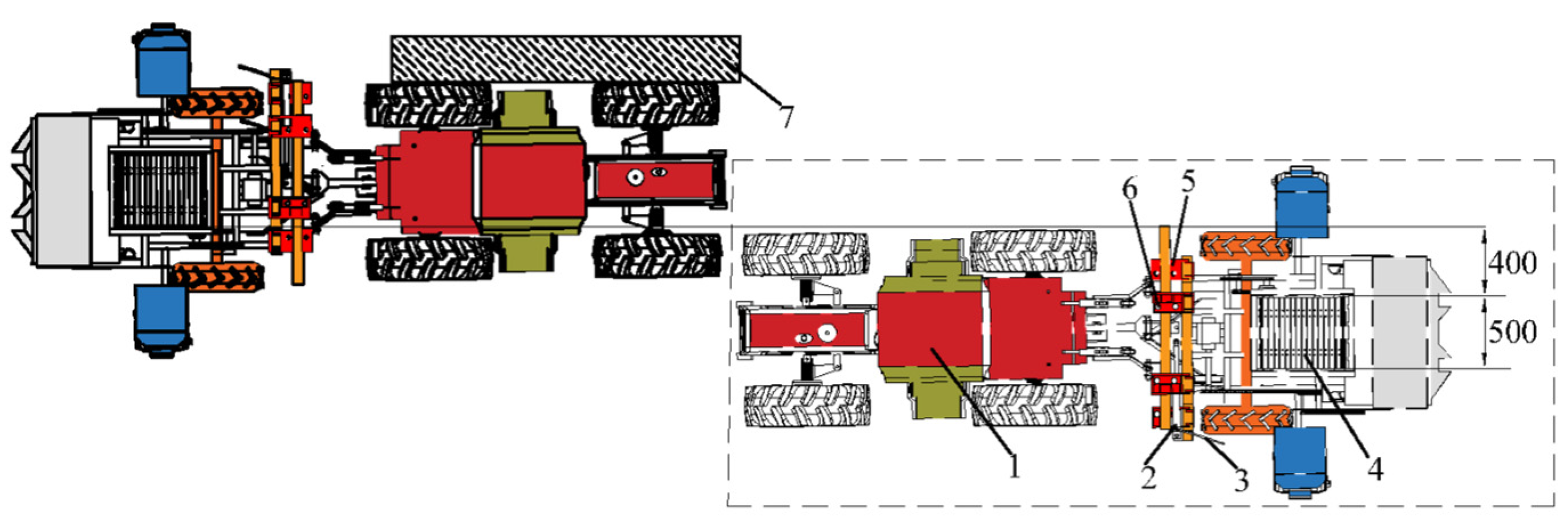
2.2. Structure of the Whole Machine

As shown in Figure 2, the machine consists of a seed bed preparation device, a seedling planting device, a soil covering device, a film covering device, an offset mechanism, ground wheels, seedling boxes, seats, and other components.

2.3. Working Principle

During operation, the Codonopsis pilosula outcrop film-laying and transplanting machine is connected to a tractor through a suspension mechanism. The machine is powered by a wheeled tractor. Under the traction of the tractor, the seed bed preparation device of the transplanting machine moves in a direction perpendicular to the ridge surface to complete trenching. The trench depth is 5 cm and the width is 50 cm. The ground wheels drive the rotation of the seedling planting device through a chain transmission. Operators manually place the Codonopsis pilosula seedlings on the seedling conveyor with the seed heads facing outward and the seed tails facing inward. The seedling conveyor transports the Codonopsis pilosula seedlings into the trench. Each trench plants one inclined seedling. Then the soil is covered on the Codonopsis seedlings with soil covering rotary blades on both sides of the machine. After soil covering, the root heads of the seedlings are 1–2 cm above the soil surface. The film covering device covers the film while simultaneously covering the soil. Finally, some soil is used to cover the sides of the film and the head portion of the seedlings through a chute, completing the entire operation process. After completing the transplanting in the first row, the hydraulic system of the tractor drives the motion of the offset mechanism, which moves the Codonopsis pilosula outcrop film-laying and transplanting machine to a suitable position for the next row of transplanting.
Since the machine adopts the method of manually placing seedlings, two people are required to continuously place seedlings on the seedling conveyor during the transplanting process. The frequency of supplying seedlings manually needs to be synchronized with the forward speed of the tractor. Therefore, it is required that the tractor can only be driven in a climbing gear during the forward process. This can effectively improve the efficiency of transplanting operations.

2.4. Main Technical Indicators

The Codonopsis pilosula outcrop film-laying and transplanting machine is designed for the double-row planting mode of Codonopsis pilosula in small plots in hilly and mountainous areas. The main technical parameters of the machine are shown in Table 1.

3. Design of Main Working Parts

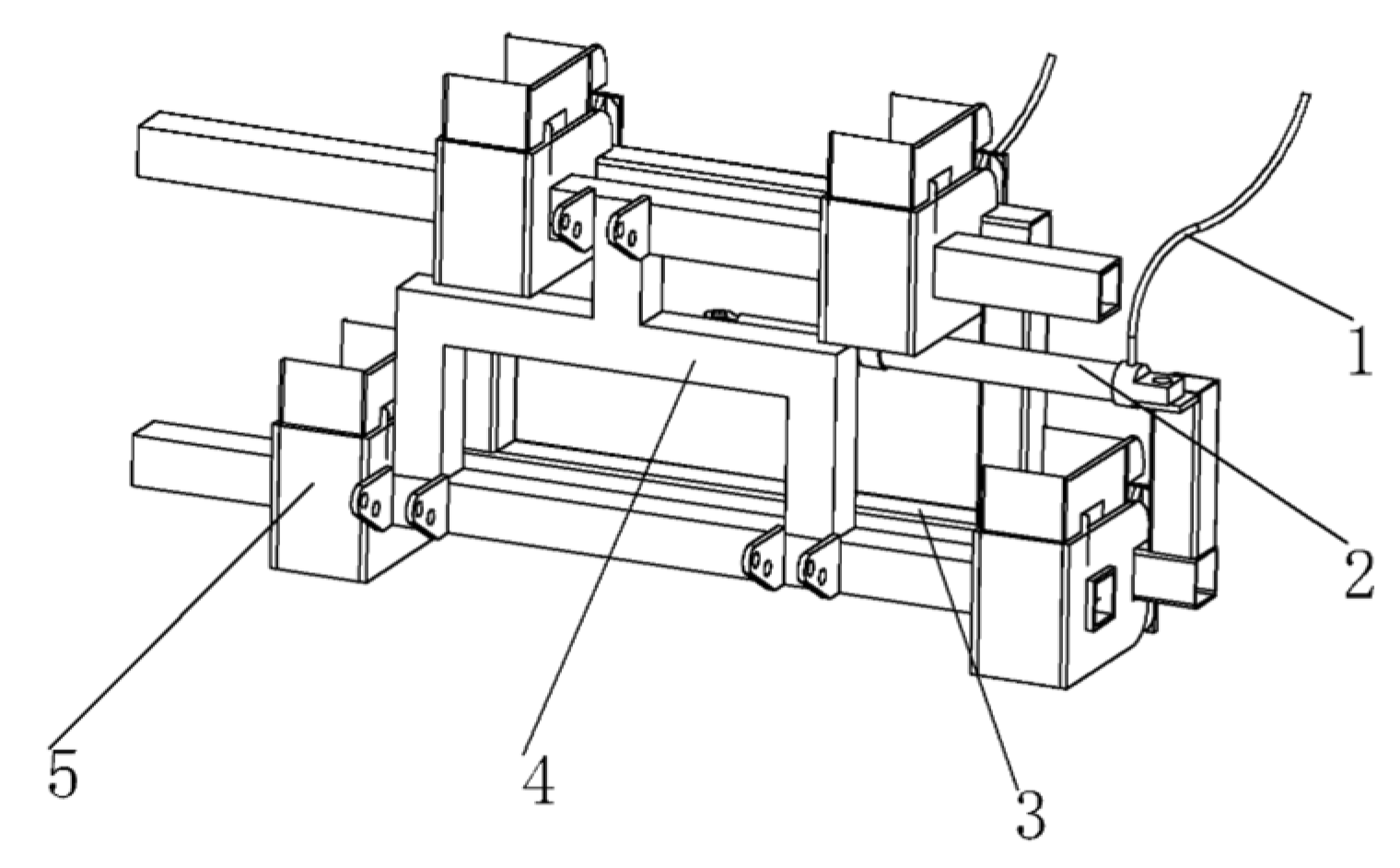
3.1. Bias Pendulum Mechanism

In the field of agricultural machinery, the application of the offset mechanism is mainly reflected in shock absorption and balance. On one hand, agricultural machinery often needs to operate on uneven terrain. In these cases, the machinery is prone to being affected by ground vibrations and bumps, which can affect the stability and efficiency of the machine. Therefore, some agricultural machinery equipment uses offset mechanisms to achieve shock absorption functions. On the other hand, in precision agriculture, agricultural machinery needs to be able to operate with precision to ensure crop growth and yield. In order to achieve this goal, some agricultural equipment used offset mechanisms for balance control [13]. In the design of the Codonopsis pilosula exposed film-laying and transplanting machine, the role of the offset mechanism is to reduce the issue of row spacing being wider than the tractor wheelbase. Since the tractor that drives the machine has a wider wheelbase than the machine itself, the actual transplanting row spacing is determined by the tractor’s wheelbase. Without the offset mechanism, the row spacing would not meet the requirements, resulting in wasted land and insufficient plant density per acre. During the process of transplanting Codonopsis pilosula seedlings, the machine needs to always lean towards the side where transplanting has already occurred. This means that every time the direction of transplanting changes It means that the machine needs to be offset relative to the tractor.

Composition and Working Principle

A bias mechanism has been designed, as shown in Figure 3, which mainly consists of an offset connector, offset auxiliary ball bearings, fixed square tubes, hydraulic cylinders, hydraulic oil pipes, and suspension brackets. After the Codonopsis pilosula outcrop film-laying and transplanting machine completes one row of transplanting, the tractor’s hydraulic system converts fluid pressure into mechanical energy through the oil pump to control the machine by driving the hydraulic cylinder. The hydraulic oil in the hydraulic system is sent into the pressure oil circuit by pressure, and the flow rate and pressure of the hydraulic oil are controlled by the regulating valve. The hydraulic oil is then transmitted to the hydraulic cylinder, which produces corresponding movement under the action of the hydraulic oil [14], thereby pushing the bias mechanism to work. The offset auxiliary ball bearing inside the bias mechanism will be driven, thus driving the whole machine to move. The Codonopsis pilosula outcrop film-laying and transplanting machine can move left and right through the bias mechanism and then adjust the machine to ensure that the row spacing of the Codonopsis pilosula seedlings remains at a wide row of 400 mm, as shown in Figure 4. Then, the second row of transplanting begins, followed by the third row, using the same procedure. The travel range of the hydraulic cylinder, that is, the adjustable range of the bias mechanism, is from 0–260 mm.

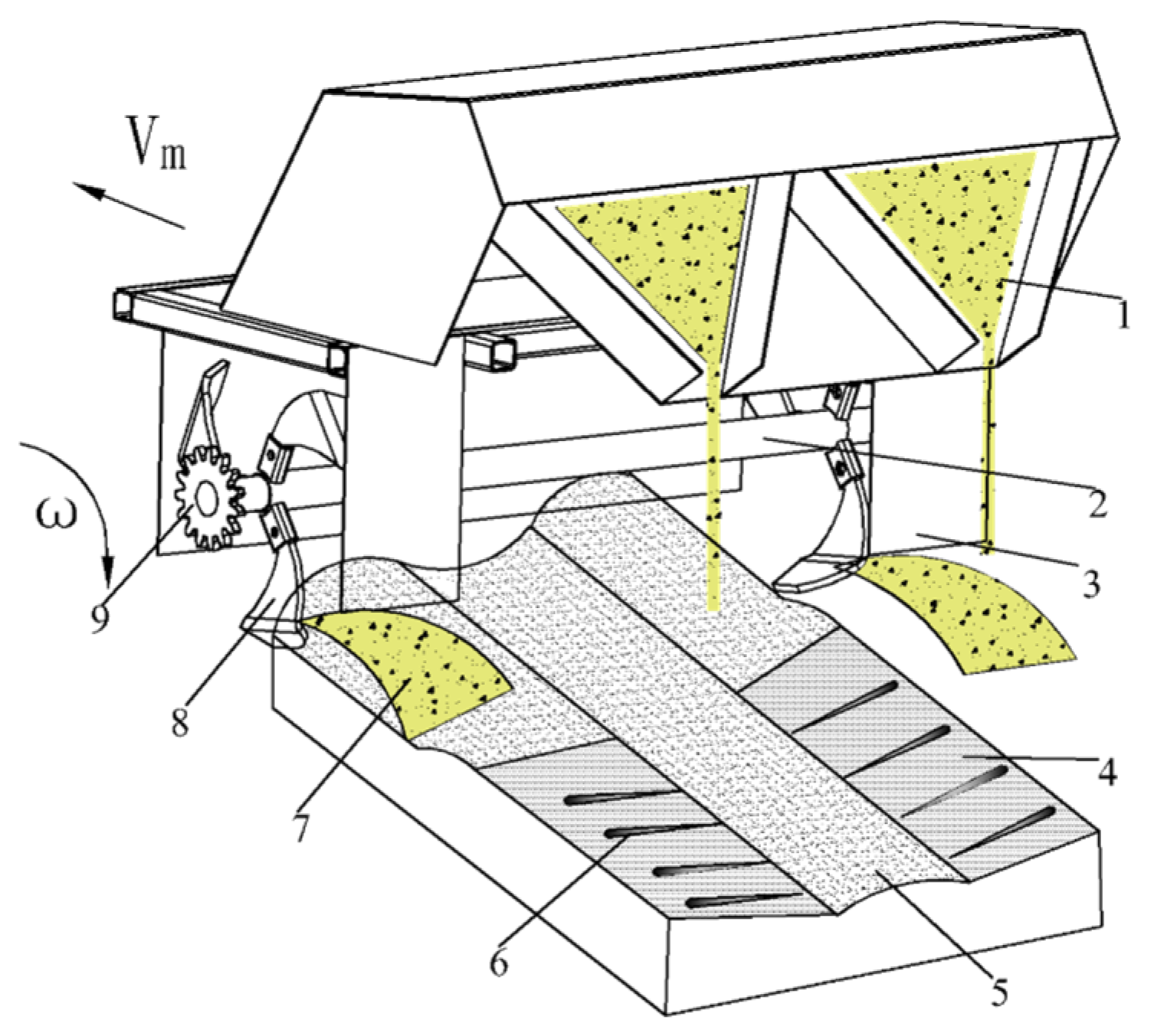
3.2. Seed Bed Preparation Equipment

The Codonopsis pilosula outcrop film-laying and transplanting machine mainly consists of seed bed preparation equipment and a seedling planting device. The seed bed preparation equipment provides a suitable bed for the growth of Codonopsis pilosula seedlings. The quality of the seed bed preparation affects the subsequent growth and yield of Codonopsis pilosula. The efficiency of the Codonopsis pilosula outcrop film-laying and transplanting machine is not only influenced by the seedling planting device but also constrained by the efficiency of the seed bed preparer. At the same time, the power of the transplanting machine is mainly consumed by the seed bed preparer. Selecting and designing a suitable seed bed preparer can effectively reduce production costs. Therefore, in this paper, based on the agronomic requirements of Codonopsis pilosula, a seed bed preparation device was designed, and relevant analysis and calculations were conducted for the seed bed preparer.
As a critical element for plant growth, soil provides nutrients and the necessary environment for the entire growth process. An appropriate seed bed for Codonopsis pilosula seedlings can provide sufficient nutrients and promote the growth of Codonopsis pilosula roots throughout the growth cycle [15]. In Gansu, the prolonged use of rotary plows has led to a shallow cultivation layer and an upward shift of the plow sole layer and thickening, which are unfavorable for Codonopsis pilosula to absorb nutrients and other growth factors from the soil during the growth cycle. According to the measurements of the mechanical and physical characteristics of the soil after crop harvest in Gansu, the average cultivation depth in the region is 150–250 mm. To construct a suitable seed bed for the growth of Codonopsis pilosula seedlings, the cultivation depth was increased during seed bed preparation. However, the power consumption of the cultivation equipment is directly proportional to the cultivation depth. Taking into account the power consumption of the cultivation operation and the quality requirements of the seed bed, the cultivation depth during Codonopsis pilosula transplanting should be set at 50–80 mm with a trench width of 500 mm.

3.2.1. Structure and Working Principle

With the improvement of mechanical development level and the transformation of agricultural production methods, many types of ditching machines are in use currently. The disc opener effectively minimizes large-scale soil disturbance in the seeding zone, creating a narrow seed trench with a width of approximately 10 mm and a depth of up to 80 mm [16]. It demonstrates superior soil-cutting performance and low energy consumption; however, it fails to meet the depth and width requirements for exposed cultivation seed beds. In contrast, the moldboard opener exhibits strong penetration capability, making it suitable for hard or clay-heavy soils while maintaining stable trench depth and width. The plow-type furrow-opening machine has low requirements for pre-sowing preparation and forms a relatively flat bottom of the furrow, which is suitable for seed germination and growth. Therefore, it is widely used in small and medium-sized sowing machines [17]. However, the traditional ditching machine operation causes large soil moisture loss due to the backfill of dry soil in the surface layer and the overturning of wet soil in the bottom layer, which cannot meet the requirements of Codonopsis pilosula’s outcrop planting. Therefore, a seed bed preparer was designed for Codonopsis pilosula’s outcroping planting, as shown in Figure 5.
It mainly consists of a furrow tip, a soil diversion plate, a soil-retaining plate, a shaper connecting rod, a shaper adjusting rod, a U-shaped screw, and a nut. The working surface of the shaper is in a triangular structure, and the hypotenuse is at a 65-degree angle with the furrow tip to ensure that the angle between the Codonopsis pilosula seedlings and the horizontal ground is 25 degrees. To meet the requirement of opening a 500 mm wide furrow for exposed planting, the distance between the soil-retaining plates on both sides of the shaper is designed as 500 mm. The shaper is fixed and connected to the frame by the connecting rod, adjusting rod, and U-shaped screw, which can be adjusted up and down to meet different requirements. When the seed bed preparer works, the shaper will cut into the soil to a certain depth according to the penetration angle, and the soil diversion plate will push the cut soil along the ridge line to split it into two parts. Then, the soil will move upward and be thrown to both sides after reaching a certain height along the soil diversion plate. The soil-retaining plate will continuously compress the side of the furrow during the working process of the soil diversion plate to prevent backfilling, thereby forming a furrow with fixed depth and stable width [18], as shown in Figure 5.

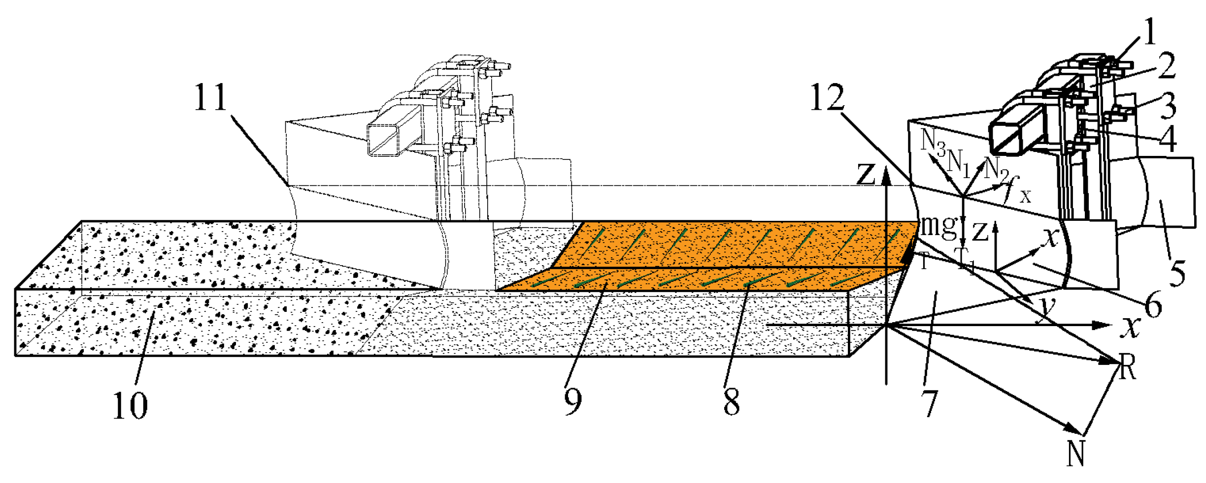
3.2.2. Force Analysis of Seed Bed Preparation Equipment into the Soil

When the shaper starts the ditching operation, the furrow tip will perform the cutting and soil-breaking work, reducing the soil reaction force acting on the furrow tip [19]. By distributing the force horizontally, the soil penetration ability of the ditching machine can be effectively improved. The force analysis of the furrow tip is shown in Figure 5.
When the shaper is working under stable conditions, the furrow tip will be subjected to a forward pressure N, and the horizontal component force F is a constant. The value of F is determined by the soil resistance of the two-faced wedge under a specific tillage depth. In the figure, β represents the friction angle of the soil, which ranges from 25° to 35° [20]. Based on the actual situation of Codonopsis transplantation, the friction angle of the soil β is set to 30°. Therefore, the force R acting on the surface of the leveler can be indirectly represented by the combined force of the forward pressure N and the frictional force T acting on the tip of the blade. The force R acting on the soil deflector when the leveler is working can be expressed as:
R = F sin α 2 + F sin α tan β cos α
R = F sin α 2 + sin 2 α 2 tan α
where α represents the angle of soil entry. By taking the derivative of the equation and setting it equal to zero, we obtain the following formula:
sin 2 α + 3 3 cos 2 α
From the above equation, we can determine the value of α that corresponds to the minimum point of the force R on the surface of the soil deflector. At this point, α represents the optimal angle of soil entry.
When the Codonopsis pilosula transplanting machine is performing field operations, the opening resistance experienced by the soil deflector is composed of the pressure exerted by the soil on the deflector and the friction between them [21]. The force acting on the soil deflector is shown in Figure 5.
The opening resistance Fy experienced by the soil deflector can be expressed as follows in the equation:
F y = f x + F N
In the equation FN is the pressure of the soil manifold by the soil, N and fx is the friction of the soil manifold by the soil, N.
When the Codonopsis pilosula transplanting machine is operating in the field, the soil exerts a certain amount of support force on the soil deflector of the leveler, including the support force of the ground on the soil deflector, the support force of the soil on both sides of the ridges on the soil deflector, and the support force of the soil extrusion resistance on the soil deflector [22]. Since the self-weight of the soil deflector mainly acts on the side of the ridge, the support force of the ground on the soil deflector is not included in the calculation of frictional force. The frictional force can be expressed as follows in the equation:
f x = μ m g + T 1 sin β + N 3
where μ is the friction factor of soil and soil manifold; m is the mass of the shaper; T1 is the support force of both sides of the monopoly body on the soil manifold; and N3 is the support force of the soil extrusion counterforce on the soil manifold.
When the structural parameters of the Codonopsis pilosula transplanting machine are determined, there will be a certain angle formed by the difference in width between the front and rear of the soil deflector, which is known as the slope angle. The soil extrusion resistance will be affected by the slope angle, and the greater the slope angle, the more significant the opening resistance experienced by the soil deflector will increase. Conversely, if the slope angle is reduced, the opening resistance experienced by the soil deflector will decrease.

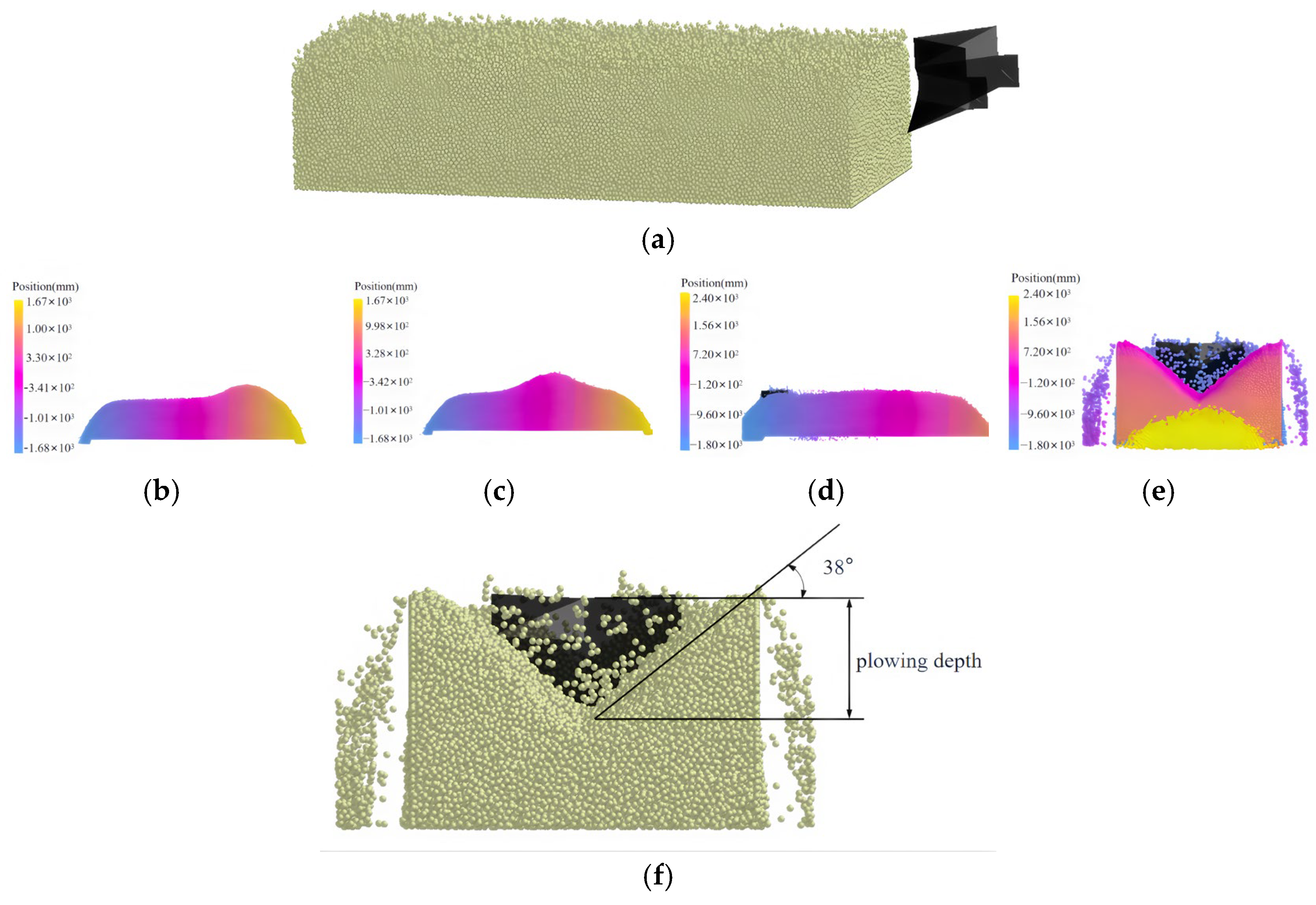
3.2.3. Simulation of the Interaction Mechanism Between Seed Bed Preparation Equipment and Soil

Determination of Soil and Machine Parameters

In order to explore the optimal working parameters and operational performance of the new seed bed preparer, a simulation analysis of the ditching process was conducted. The experimental soil used was sandy loam, which is loose and compressible. The physical properties of the soil include particle size distribution, soil density, shear modulus, Poisson’s ratio, etc. [23]. The contact parameters include restitution coefficient, static friction coefficient, and rolling friction coefficient. After obtaining the basic parameters required for soil discrete element simulation through literature research. A simulation analysis of the ditching process of the seed bed preparations was conducted and is shown in Table 2. The primary parameters were selected based on existing literature [24,25,26,27].

Discrete Element Simulation Modeling and Analysis
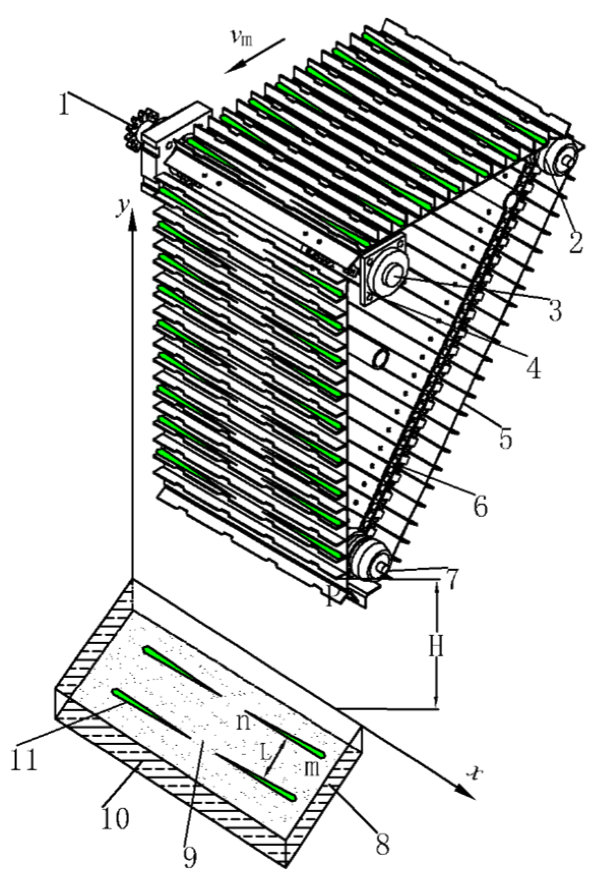
Currently, the particle size of soil modeling used in discrete element simulation research for cultivation is generally larger than the actual size of soil particles. Considering the simulation accuracy and computer performance, this study uses a variable-diameter spherical particle model to replace the actual soil particles, and the particle size range and ratio are shown in Table 3. The mass fraction set in the particle size range is based on the average value of the measured mass fraction, and the simulated particle size is ten times the arithmetic mean of the actual soil particle size [28].
As shown in Figure 6, The EDEM software was used to simulate the operation process of the seed bed preparer, which mainly includes the contact and collision between soil particles and the soil-contacting parts. The key is the contact model between soil particles. Common contact models in the EDEM 2020 software include the Hertz–Mindlin (no slip) model, Hertz–Mindlin with Bonding model, JKR model, Linear Cohesion model, Linear Spring model, Moving Plane model, etc. In this study, we do not consider heat transfer and wear issues and use the common Hertz–Mindlin (no slip) model as the contact model between the discrete element simulation soil particles and the seed bed preparer.
Once the generation of the simulated particles was complete and their distribution was stable within the simulated soil, the 3D model of the seed bed preparator was imported into the EDEM 2020 software. Subsequently, the model was positioned at one end of the simulated soil trench. During the simulation process, the depth of the seed bed preparer into the soil could be adjusted to ensure the accuracy and reliability of the simulation results. Additionally, the reasonableness of the design was verified by verifying the width of the open furrow, the angle of the open furrow incline, and the horizontal plane. The final step was to set the forward speed of the seed bed preparator to 0.25 m/s for the simulation.
Through simulation experiments, the trenching process of the seed bed preparer can be analyzed and compared with the actual field test results. The results of the field experiment demonstrated that the seed bed preparer had a trenching depth of 65 mm and a width of 500 mm. The planting angle of the Codonopsis pilosula seedlings was observed to be 32°. As shown in Figure 6, depth can be adjusted on a case-by-case basis, width is 492 mm, and planting angle is 38°. The simulation results are within 5% of the experimental data and meet the requirements of Codonopsis pilosula outcrop cultivation. Therefore, the trench width and planting angle in the simulation results verified the correctness and rationality of the design.

3.3. Seeding Device

The seeding device is the core component of the Codonopsis pilosula uncovered film transplanting machine, and good seedling delivery performance is the basis for ensuring planting performance. In order to meet the agricultural and planting requirements in China, some scholars have proposed various forms of seedling picking mechanisms, such as top-out, top-out and gripping, insertion and gripping, and pneumatic methods [29]. Although these methods have good seedling-picking effects, the seedling-picking trajectory is complex and affects the stability of seedling-picking. Therefore, in order to improve transplanting efficiency, this design adopts the method of manual seed placement with mechanical assistance in seed delivery. Future implementations could employ machine vision (e.g., RGB-D cameras or hyperspectral imaging) to achieve morphological recognition and precise positioning of Chinese medicinal herb seedlings [30,31]. Deep learning algorithms (YOLO, Mask R-CNN, etc.) may be adapted to accommodate the diversity of rhizomatous herbs like Codonopsis and Astragalus, while pneumatic soft grippers or biomimetic robotic arms could significantly reduce seedling damage rates [32,33].
As shown in Figure 7, the seedling delivery device mainly consists of a seedling groove driving gear, a seedling groove driving shaft, a chain, a seedling groove, a chain plate driving pulley one, a chain plate driving pulley two, a chain plate driving pulley fixed shaft, a bearing seat, etc. It is fixedly installed above the frame, and as the implement advances, the ground wheel drives the seedling groove driving gear to rotate. The seedling groove driving gear drives the seedling groove driving shaft to rotate at a speed of V, and then the seedling groove driving shaft drives the chain plate driving pulley fixed shaft to rotate. The seedling groove driving shaft and the chain plate driving pulley fixed shaft jointly maintain the reciprocating rotation of the seedling delivery chain plate. Manually place the Codonopsis pilosula seedlings parallel to both sides of the planting trench on each seedling groove. As the seedling delivery chain plate rotates, the seedlings are evenly placed in the soil, realizing accurate seedling delivery. The two main parts that drive the delivery of Codonopsis pilosula seedlings are the chain and the metal chain plate, which provide traction power through their cyclic reciprocating motion and serve as the carrier during the transportation process, respectively. The principle is mainly to use a series of chains fixedly connected to the traction chain to provide traction force and use a metal chain plate as a carrier to guide Codonopsis pilosula seedlings to be transported horizontally or vertically.

3.3.1. Analysis of Seedling Planting Movement

In order to determine the factors that affect the seedling delivery effect and to establish evaluation indicators for the seedling delivery experiment, the horizontal motion process was analyzed to determine the impact of the seedling delivery rate on the seedling delivery effect. The vertical motion process was also analyzed to determine the impact of the seedling drop height on the seedling delivery effect. Figure 7 shows a side view of the seedling delivery process, while Vm is the forward speed of the transplanting machine. Assuming that the head of the seedling falls into point m and the root falls into point n after being thrown out from point p at a height of H and the horizontal displacement of the seedling is denoted as L, a Cartesian coordinate system is established with the X-axis as the horizontal direction and the Y-axis perpendicular to the horizontal plane. It is known that the air resistance to the seedling is proportional to its movement speed [34]:
f = μ v
where f is the air resistance, N; μ is the air resistance coefficient, and v is the seedling speed, mm/s.
The force acting on the seedlings during the seedling delivery operation is shown in Figure 8. At a certain moment during the seedling delivery motion, the seedlings are subjected to the forces of gravity and air resistance. Based on Newton’s second law, we can establish a differential equation for the motion and explore the factors affecting seedling delivery.

3.3.2. Analysis of Horizontal Direction Planting Movement

By analyzing the horizontal motion process during the descent of the seedlings, we can explore the impact of the seedling delivery speed on the seedling delivery effect.
f x = m a x
where m is the mass of the seedling, g; ax is the horizontal acceleration of the seedling, mm/s2.
By integrating the above equation, we can obtain the horizontal velocity of the seedlings during motion as:
v x = v 0 e μ t m
where vx is the horizontal direction of the seedling movement speed, mm/s; v0 is the seedling throwing speed, mm/s; and t is the movement time, s.
Integrating the above equation again, the horizontal displacement of the seedling can be obtained as:
L = v 0 t m μ e μ t m
where L is the horizontal displacement of the seedling, in mm.

3.3.3. Vertical Direction Seedling Throwing Motion Analysis

By analyzing the vertical motion process, we can explore the impact of the seedling drop height on the seedling delivery effect.
G F f = m a y
where ay is the vertical acceleration of the seedling, mm/s2.
Integrate the above equation to get the vertical direction movement speed of the seedling as:
v y = m g μ ( 1 e μ t m )
where vy is the speed of the vertical direction movement of the seedling, mm/s.
Integrating the above equation again, the vertical displacement of the seedling is obtained as:
y = m 2 g μ 2 ( e μ t m 1 )
where y is the vertical displacement of the seedling, mm. Without considering the effect of μ on the effect of seedling casting, the vertical displacement is:
lim y μ 0 = m 2 g 2 μ t m e t m μ = 1 2 g t 2
From the equation, it can be seen that when μ tends to 0, the value of y tends to approach 1/2 gt2. In this case, when the planting height is fixed and the vertical displacement is determined, the motion duration t of the seedlings can be determined. Moreover, the air resistance has almost no effect on the delivery of the seedlings. Since the displacement of the Codonopsis pilosula seedling depends on the initial speed of the Codonopsis pilosula seedling out of the seedling transporting chain plate and the height of the seedling, while the speed of the Codonopsis pilosula seedling in the seedling transporting chain plate is fixed, and the plant spacing of the ginseng is determined to be n = 40 mm, it means that the center distance between the two neighboring chain plates is 40 mm; therefore, the length of the chain plate of the seedling transporting chain in the vertical direction is taken as L = 20 n = 800 mm. Therefore, the final design determines the length of the seedling groove in the vertical direction to be 800 mm.
The kinetic energy of the seedlings when thrown towards the ground can be expressed as:
T = m 2 v m 2 = m 2 v x 2 + v y 2
where T represents the kinetic energy of the seedlings, measured in J.
Based on Equations (8) and (11), it can be inferred that for a single seedling, the mass m remains constant while the initial velocity v0, air resistance coefficient μ, and motion time t will affect the seedling’s velocity. Similarly, from Equations (9) and (12), it can be inferred that for a single seedling, the mass m remains constant while the initial velocity v0, air resistance coefficient μ, and motion time t will affect the horizontal position of the seedling’s landing point. Furthermore, considering Equation (14) as a whole, both the planting height and planting velocity will have an impact on the success rate of seedling transplantation.

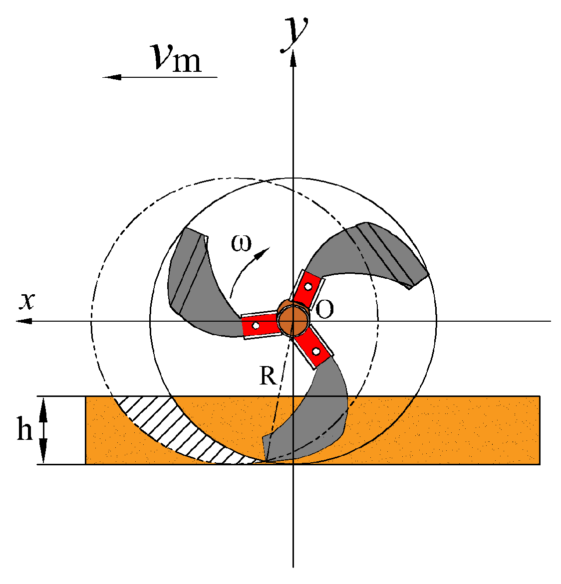
3.4. Covering Device

After completing the procedures of trenching, seedling placement, and seedling delivery, the soil flipped from both sides of the trench should be compacted over the seedlings to improve their survival rate. As shown in Figure 9, the covering device of the Codonopsis pilosula mulch-laying and transplanting machine is mainly composed of a rotary tillage shaft, drive sprocket, soil covering rotary tillage blade, ridge-forming support, soil-guiding plate, soil-blocking plate, etc. When the machine moves forward, the power from the gearbox is transmitted to the covering device through the intermediate shaft, driving the sprocket to rotate, and then the sprocket drives the rotary tillage blade to start rotating and enter the soil. Due to the design of the rotary tillage blade and its rotating motion, it can form a curved cutting surface in the soil, separating the upper layer of soil from the lower layer [35]. The soil covering the rotary tillage blade flips the cut soil and covers it along the edge of the plastic film, completing the covering operation at the film edge. At the same time, some of the broken soil is flipped into the soil-guiding plate. During the forward movement of the Codonopsis pilosula mulch-laying and transplanting machine, the fine soil is axially conveyed through the soil-guiding plate, and the soil is scattered in the gap between the soil-guiding plate and the soil-blocking plate, evenly covering the film surface and forming two strips of soil, completing the seedling-covering operation.

Kinematic Analysis of Rotary Tiller Blade Motion

During rotary tillage operation, the rotary tillage blade moves forward with the machine tool while rotating, and the motion trajectory of each point is a trochoid. Under the same operating parameters, the motion trajectory equations obtained from forward and reverse rotations are identical [36]. This paper only presents the kinematic analysis of the rotary tillage blade’s reverse rotation. A Cartesian coordinate system is established with the axis of rotation of the blade as the origin, and the direction of machine advancement is taken as the positive X-axis. During reverse rotation, the positive direction of the Y-axis is vertically upward, as shown in Figure 10.
As mentioned above, the coordinate system established at this point represents the reverse rotary ploughing motion with the equation of motion:
x = R cos ω t + v m t y = R sin ω t
where R is the rotary radius of the rotary ploughing knife endpoint, mm; ω is the rotary angular speed of the rotary ploughing knife, rad/s; t is the movement time, s; and vm is the forward speed of implements, m/s;
Through the derivation of the above equation, the rotary ploughing knife end point speed equation can be obtained as:
v x = d x / d t = v m R ω sin ω t v y = d y / d t = R ω cos ω t
where vx is the rotary ploughing knife endpoint x-axis partial velocity, m/s; vy is the rotary ploughing knife endpoint y-axis partial velocity, m/s.
Associating the above equation, the absolute velocity equation of the end point of the rotary ploughing knife is:
v = v x 2 + v y 2 = v m 2 + R 2 ω 2 2 v m R sin ω t
where v is the absolute speed of the rotary ploughing blade endpoint, m/s
From the above equation, it can be seen that during the motion of the rotary tillage component, the velocity of the blade endpoint continuously changes with time. When Vx > 0, there is mutual compression between the soil and the back of the blade, which can lead to soil accumulation in front and affect the operation of the machine. When Vx < 0, the cutting edge cuts the soil backward and throws it, allowing the rotary tillage blade to operate normally. Therefore, the component velocity of the blade endpoint in the x-axis direction must be less than 0.
Let the depth of ploughing of the rotary ploughing component be h; then we have:
h = R y = R R sin ω t
and must be satisfied to be less than zero, then:
R > h + v / ω
when the Codonopsis pilosula transplanting machine is operating normally, the forward speed of the unit, v, is within the range of 0.25 to 1.11 m/s. The rotary tillage depth, h, is between 50 and 80 mm. The rotational speed of the rotary tillage blade shaft is between 270 and 360 r/min, corresponding to a roller rotation angular velocity, ω, of 28.28 to 37.70 rad/s. By substituting the data into the equation for analysis and calculation, the rotating radius of the rotary tillage blade must be greater than 119.25 mm.

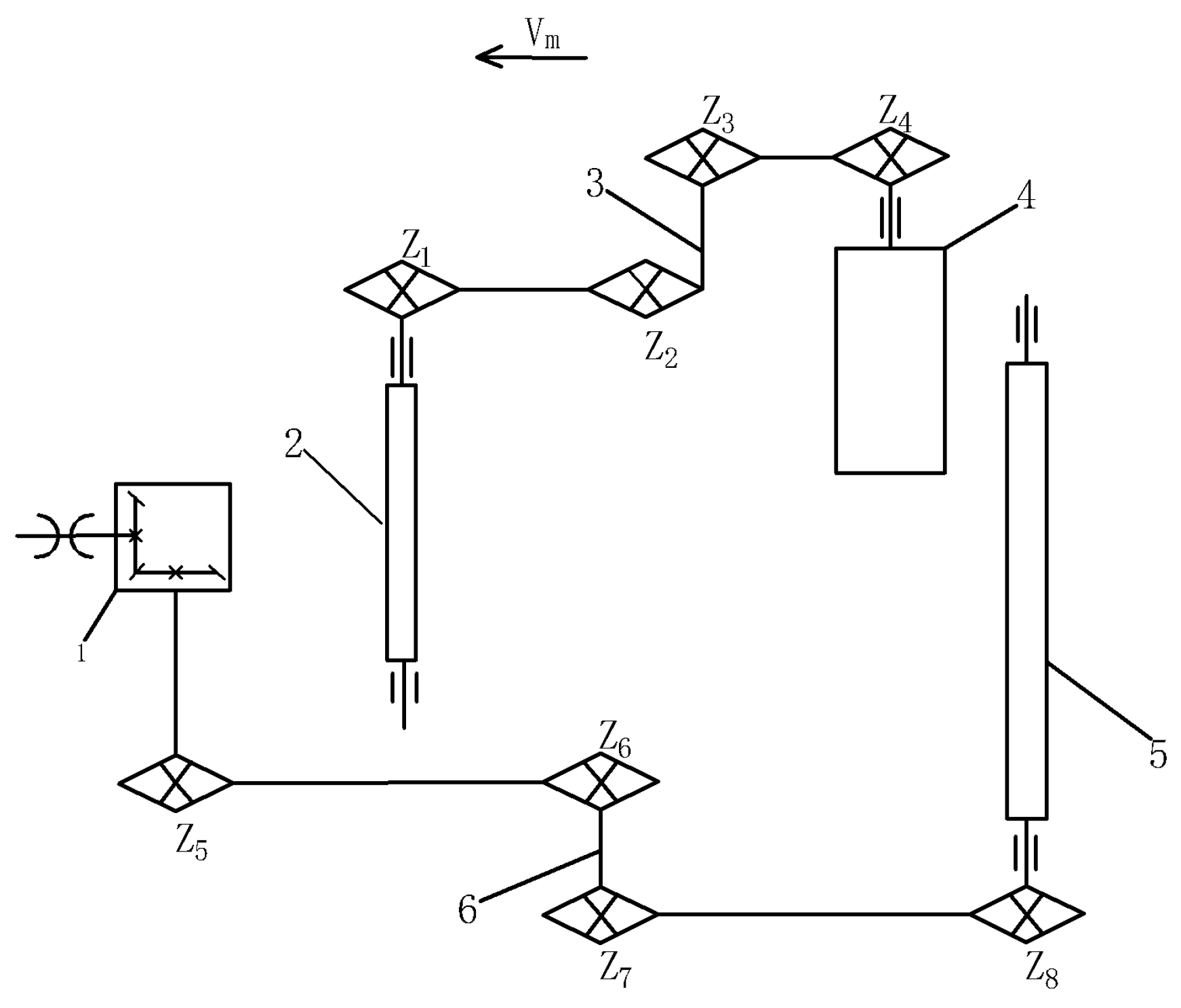
3.5. Transmission System Design
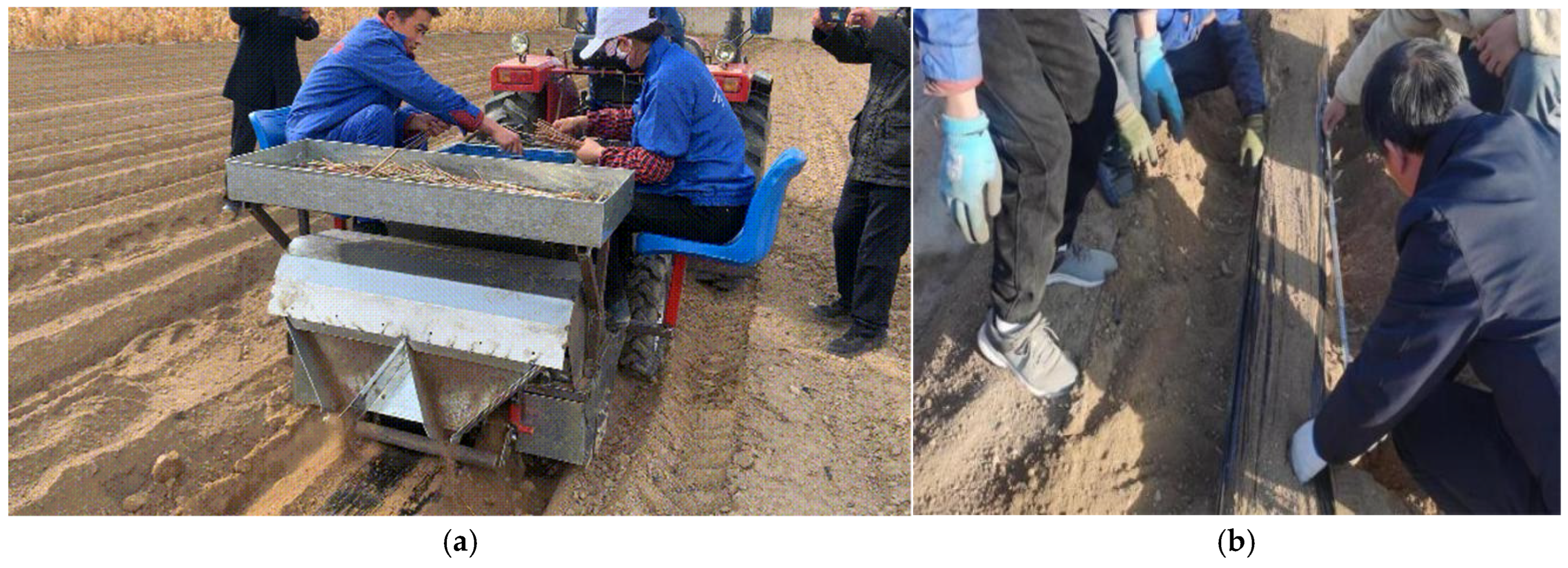
Compared to belt drives, chain drives exhibit a more compact structure, higher power transmission capacity, and superior overload tolerance, with reduced radial pressure on the drive shaft. When contrasted with gear drives, chain drives require lower installation precision and demonstrate significant cost advantages. Specifically optimized for agricultural applications, chain drive systems accommodate shaft center distances of 5–6 m, maintain transmission ratios below 8:1, and operate at chain speeds ≤ 15 m/s, effectively meeting diverse agricultural mechanization demands [37]. The transmission system of the Codonopsis pilosula mulch-laying and transplanting machine is shown in Figure 11. The machine mainly adopts chain drive, while the power from the ground wheel is transmitted to the intermediate shaft through chain drive. When the intermediate shaft drives the chain plate conveying seedling device, the power input shaft of the chain plate conveying seedling device drives the rotation of the seedling conveying chain plate, thereby completing the transplanting operation. The gearbox transmits power to the sprocket through the power output shaft, and the sprocket transmits power to the rotary tillage and covering device through the intermediate shaft using chain drive. Due to the large distance between the gearbox output and the rotary tillage and covering shaft, as well as the ground wheel shaft and the seedling conveying device, the center distance of the chain drive becomes too large, resulting in excessive sag and vibration, which reduces the transmission efficiency. To solve this problem, an intermediate shaft is designed and installed on the frame to transmit the power from the gearbox output to the rotary tillage and covering device through the intermediate shaft [38]. In this way, the power provided by the ground wheel can drive the rotation of the seedling conveying device through the intermediate shaft, thus realizing the functionality of the machine.
The ground wheel, as the main power source for driving the linear seed supplying mechanism, directly determines the stability of the automatic seed supplying operation based on its reliability. However, the diameter of the ground wheel is a key factor that affects its strength. After final design considerations, the diameter of the ground wheel has been determined as 500 mm.
The rated speed of the engine power output shaft is 540 rpm. When the implement speed is 0.25 m/s, the ground wheel speed of the Dong Fang Hong SG354 tractor in creeper gear is:
n = 60 v 2 π r
where v is the forward speed of the machine, m/s; r is the radius of the ground wheel, mm. From Equation (20), the rotational speed of the ground wheel shaft is 9.5 r/min.
The rotational speeds of the various sprockets in the chain drive are calculated according to the following formula:
n z n c = Z c Z z
where nz is the rotational speed of the master wheel, r/min; nc is the rotational speed of the driven wheel, r/min; Zz is the number of teeth of the master sprocket; Zc is the number of teeth of the driven sprocket.
Among them, the active sprocket connected to the ground wheel is selected with 26 teeth, the driven sprocket is selected with 15 teeth, the transitional sprocket is selected with 42 teeth, the driving sprocket of the seedling-supplying mechanism is selected with 12 teeth, the sprocket on the output shaft of the gearbox is selected with 10 teeth, the sprocket on the input shaft of the intermediate shaft is selected with 15 teeth, the sprocket on the intermediate shaft that matches the rotary tillage and covering device is also selected with 15 teeth, and the sprocket that drives the rotary tillage and covering device is also selected with 15 teeth. Based on the selected number of teeth and the speed of the power output shaft, the rotational speed of the driving shaft of the machine for the seedling supplying mechanism is calculated as 20.6 r/min, and the rotational speed of the active shaft of the rotary tillage and covering device is calculated as 360 r/min. Given the rotational speed of the driving shaft, the linear velocity of the seedling conveying chain plate can be calculated using the following formula:
v s = n z × 2 π r z
where vs is the linear speed of the seedling transporting chain plate, mm/min; rz is the radius of the active wheel, mm;
Among them, the radius of the active wheel of the seedling-transporting chain plate is 40 mm, and then the linear speed of the seedling- transporting chain plate is 0.09 m/s.
To ensure the smooth process of seedling delivery during the transportation of Codonopsis seedlings on the seedling conveying chain plate, it is necessary to ensure that the forward speed of the machine is greater than the linear velocity of the seedling conveying chain plate. Based on the previous calculations, the linear velocity of the seedling conveying chain plate for the Codonopsis transplanter is determined to be 0.09 m/s, while the speed of the tractor’s crawler gear is 0.25 m/s. By calculating, it can be confirmed that the seedling conveying chain plate meets the transport requirements.

4. Field Experiment

4.1. Experimental Condition

The field test was carried out on 20 May 2023 at the test site of Dingxi City Sanniu Agricultural Machinery Manufacturing Corporation Chan Kou Town, Dingxi City, Gansu Province (as shown in Figure 12). The length of the test plot should be not less than 20 m, the preparation area at both ends should be not less than 10 m, and the width should meet the test requirements. The condition of the test plot was adjusted, and the method of soil preparation and soil texture were recorded; finally, the length of the test plot was determined as 40 m, the width as 10 m, and the soil texture as sandy loam. The average value of soil water content was 14.53%, and soil capacity was 1.128 g/cm3, which met the requirements of “T/NJ 1207–2020 Roots and Stems Chinese herbal medicine transplanting machine” for transplanting test soil. The seedlings of Codonopsis pilosula were taken from the locally grown white-striped Codonopsis pilosula, with an average seedling length of 200 mm and a seedling diameter of about 3 mm.

4.2. Experimental Test and Methodology

The transplanting machine of Codonopsis pilosula was powered by a Dong Fang Hong SG354 tractor with a power of 25.7 kW. The transplanting machine was towed by the three-point hitch, and the operating speed was controlled at 0.25 m/s. Two hundred plants were measured per plot, and 17 repeated field experiments were conducted on the transplanter according to the above operating conditions. Theoretically, the transplanting spacing of Codonopsis pilosula seedlings was 40 mm, the planting angle was 25°, and the planting depth was 50 mm. The transplanting efficiency (number of plants transplanted per unit of time) is an important parameter for evaluating the performance of transplanting machines. The assessment of transplanting quality mainly includes the plant spacing qualification rate and the planting depth qualification rate. Therefore, the plant spacing qualification rate and the planting depth qualification rate are selected to comprehensively evaluate the plant spacing accuracy and planting depth of the Codonopsis pilosula film covered exposed transplanting machine. The levels of the experimental factors are shown in Table 4.
According to the relevant experimental methods for transplanting machinery in the Mechanical Industry Standard of the People’s Republic of China T/NJ 1207-2020, performance tests are conducted with tractor forward speeds of 0.25 m/s, 0.3 m/s, and 0.35 m/s. The average forward speed of the machine is maintained at the specified test speed. After each test, measurements are taken over five segments, each with a continuous length of no less than 5 m. A planting depth between 50 and 60 mm is considered qualified, and a plant spacing between 40 and 50 mm is considered qualified. The qualification rates for planting depth (Y1) and plant spacing (Y2) are calculated as follows:
  • Pass rate for planting depth
After covering the rhizomatous medicinal materials with soil, carefully remove the soil cover in each small area to measure the thickness of the soil covering the seedling emergence point. The requirement for the qualified planting depth rate is ≥80%. The qualified planting depth rate is calculated using the following formula.
H = H h H z × 100 %
Formal:
  • H—Planting depth pass rate; in percent (%);
  • Hh—The sum of the number of eligible planting depths in each plot, in units of;
  • Hz—Total number of plants measured in each plot, in pieces.
2.
Pass rate for spacing
Measure the distance between adjacent seedling heads within each small area. The requirement for the qualified plant spacing rate for seedling planting is ≥80%. The qualified plant spacing rate is calculated using the following formula:
J = J h J z × 100 %
Formal:
  • J—Plant spacing qualified rate; the unit is a percentage (%);
  • Jh—Sum of qualified number of plant spacings of each cell, unit is each;
  • Jz—The total number of plant spacings was measured in each plot, and the unit was one.

4.3. Analysis of Experimental Results

4.3.1. Experimental Results

The three-factor, three-level experimental design includes 17 test groups (5 groups for zero-point estimation errors and 12 groups for analyzing factors). The experimental design and results are shown in Table 5.

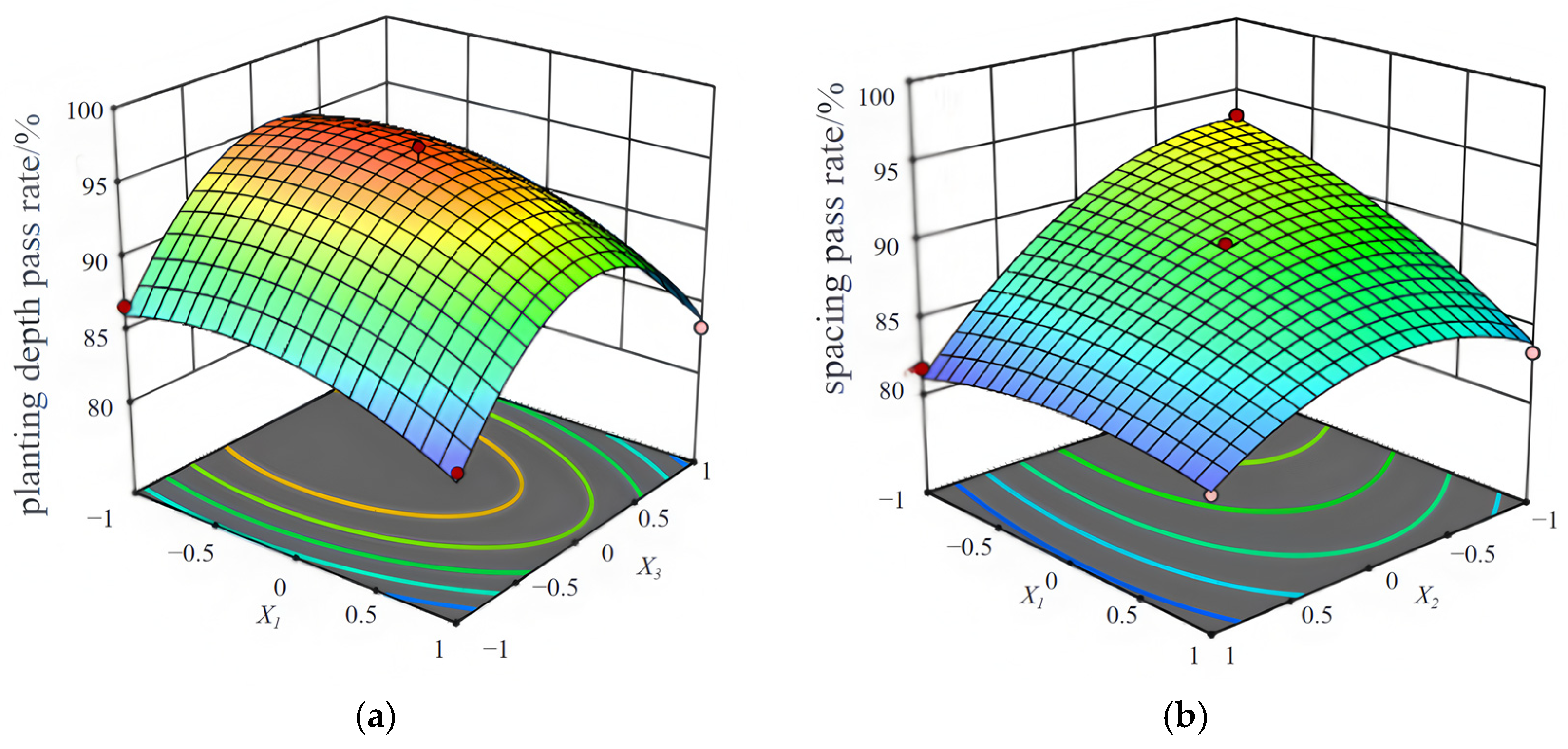
4.3.2. Regression Equation Building and Analysis

Using Design-Expert, a variance analysis of the regression model for planting depth qualification rate (Y1) and plant spacing qualification rate (Y2) was conducted, as shown in Table 6 and Table 7.
By substituting the obtained relevant parameters into the equation, the regression models for planting depth qualification rate and plant spacing qualification rate are as follows:
Y 1 = 95.68 2.10 X 1 0.2125 X 2 + 1.04 X 3 + 1.25 X 1 X 2 0.4 X 1 X 3 + 0.825 X 2 X 3 2.43 X 1 2 + 0.4975 X 2 2 7.85 X 3 2
Y 2 = 89.66 3.52 X 1 2.09 X 2 + 1.46 X 3 + 2.50 X 1 X 2 0.45 X 1 X 3 0.025 X 2 X 3 3.37 X 1 2 1.29 X 2 2 + 4.96 X 3 2
As shown in Table 6, the planting depth qualification rate model has p < 0.01, indicating that the regression model is highly significant; the lack-of-fit term has p > 0.05, suggesting that the lack of fit is not significant, meaning that the quadratic regression equation fitted by the model aligns well with the actual data and can correctly reflect the relationship between the planting depth qualification rate Y1, X1, X2, and X3. The regression model can effectively predict various experimental results in the optimization experiment. Among the terms in the model, the linear term X1 has an extremely significant impact, the quadratic terms X12 and X32 have an extremely significant impact, X3 has a significant impact, and the other terms are not significant. Based on the size of the regression coefficients of each factor in the model, the order of influence on the planting depth qualification rate is X1, X3, and X2.
The model for the plant spacing qualification rate, as shown in Table 7, has a p-value of less than 0.0001, indicating that the regression model is highly significant. The lack-of-fit term has a p-value >0.05, suggesting that the lack of fit is not significant, meaning the quadratic regression equation fitted by the model aligns well with the actual data. It accurately reflects the relationship between the plant spacing qualification rate Y2 and the variables X1, X2, and X3. The regression model can predict the results of various experiments in the optimization process with good accuracy. Among the terms, the linear terms X1, X2, and X3 are highly significant, the quadratic terms X12 and X32 are highly significant, and the interaction term X1X2 is significant, while the other terms are not significant.
The response surface plots for the relationships between the factors are generated based on the regression models, respectively.
As shown in Figure 13a, when the chain speed is at the medium level and the planting depth is fixed at a certain value, the qualification rate of planting depth decreases as the machine forward speed increases. This is because when the machine moves too quickly, the time for the soil covering device to operate is reduced, which leads to a decrease in the amount of soil covered, affecting the qualification rate of planting depth. When the machine’s forward speed remains constant, the qualification rate of planting depth first increases and then decreases as the soil entry depth increases. This is because when the entry depth of the seed bed preparation device is small, the planting of the Codonopsis is too shallow. However, when the entry depth is too large, the planting becomes too deep, both of which result in a decline in the qualification rate of planting depth.
As shown in Figure 13b, the qualification rate of planting depth decreases as the machine forward speed and chain speed increase. The main reason for this phenomenon is that when the machine and chain speeds are too fast, the Codonopsis seedlings, which are relatively long, get scraped by the chain at high speeds. This causes the seedlings to shift or tilt, leading to a decrease in the qualification rate of plant spacing.
The number of Codonopsis seedlings planted after the experiment was counted by selecting five 1 m2 plots, with the number of seedlings in each plot being 44, 48, 40, 51, and 47, respectively. The average number of seedlings, 46, was taken for estimation. Therefore, the planting density of Codonopsis seedlings for this membrane-covered head-out transplanting machine design is 30,668 plants per acre. The Codonopsis pilosula mulching and transplanting machine can complete 0.2 hm2 per day after 10 h of operation, and the cost of transplanting 1 hectare is roughly estimated to be 3280 RMB. Labor costs per hectare are approximately 7200 RMB, as 10 people can complete 0.18 hectares of land with a daily labor of 10 h. Each worker costs 130 yuan per day, resulting in a cost savings of 3920 RMB compared to manual labor. Using artificial cultivation, each person can only work 0.018 hm2 per day (calculated as 10 h), while using machinery (with manual assistance), each person can work 0.04 hm2 per day. The efficiency of mechanical operation is 2.2 times that of manual operation [37]. The Codonopsis membrane-covered head-out transplanting machine in this design meets the national and industry standards for plant spacing qualification rate and planting depth qualification rate, as determined by field experiments. During operation, all components function smoothly without any failures, demonstrating high reliability.

5. Discussion and Conclusions

Based on the current situation of Codonopsis transplantation in the arid region of Northwest China, the Codonopsis pilosula outcrop film-laying and transplanting machine was designed.
The design of key components of the machinery was carried out, including the structure and related parameters of the seed bed preparator, seedling planting device, soil covering device, and transmission system, which ensures the proper transplanting of Codonopsis seedlings, and the intended working process was achieved.
Based on discrete element simulation, the optimized design of the soil entry angle for the seed bed preparation device ensures the stability of the trench depth; the swing mechanism achieves precise adjustment of row spacing, and the synchronous control mechanism between the seedling transport chain plate and the machine travel speed achieves the qualified rate of plant spacing and planting depth.
Field experiment results indicate that at forward speeds of 0.20, 0.25, and 0.3 m/s, the average qualified rate of planting depth is 91.08%, and the average qualified rate of plant spacing is 89.8%. The experimental results meet the design requirements, demonstrating that the machine can accomplish the entire operation process of seed bed preparation, seedling placement, rotary tillage, mulching, and soil covering in one go. These field performance indicators meet both national and industry requirements.
The mechanized outcrop cultivation technology of traditional Chinese medicine not only solves the problems of high machine power consumption and root and stem loss rate but also effectively solves the problem of increased soil resistance caused by deep excavation in the harvesting process, making it suitable for large-scale promotion in hilly and mountainous areas. In the future, key technologies such as automatic separation of seedlings and automated seedling placement need to be gradually developed to ensure the plant spacing, row spacing, and depth indicators for seedling transplantation and to improve the comprehensive mechanization level.

Author Contributions

Conceptualization, W.S. and M.Z.; software, J.B., J.W. and P.A.S.; investigation, J.B., W.S., M.Z. and L.Z.; resources, W.S., J.W. and P.A.S.; writing—original draft preparation, J.B.; writing—review and editing, W.S., P.A.S., M.Z., L.Z. and J.B.; supervision, M.Z., L.Z., J.W. and P.A.S.; project administration, W.S.; funding acquisition, W.S. All authors have read and agreed to the published version of the manuscript.

Funding

This research was funded by the Central-Guided Local Science and Technology Development Fund Project (25ZYJA036), the Gansu Province Agricultural Machinery Equipment Shortcomings Action Project (njyf2024-03-1), and the Gansu Provincial University Industry Support Plan (2022CYZC-42).

Data Availability Statement

Data are reported within the article.

Conflicts of Interest

The authors declare no conflicts of interest.

References

  1. Ma, X.L.; Zhang, L.H.; Liu, P.X.; Li, S.L. Analysis of the current status and advantages of mechanised ginseng cultivation in Gansu. J. Promot. Agric. Mach. Sci. Technol. 2022, 29–31. Available online: https://kns.cnki.net/kcms2/article/abstract?v=cwBM1amFwwP9BkPOK-BT4Q57zmLbmMrhrv_Wxtv_6nBUxd5_BaDECjK_0Z-GIHg9x1DkCc0FPukH6Eyiwg5cASxLpekHEOHOPTdbolJb-0Lr6hztRvnKMAWuwhYeBVJ4jYbLa0TmLTK_z3EjYhCYyRAgzhUaWGlF36WeomiQ6Wzb6ASOqsvwDw==&uniplatform=NZKPT&language=CHS (accessed on 17 December 2024).
  2. Lv, G.Q. Gansu ginseng industry technology innovation strategy alliance set up. Gansu Daily News-Lanzhou Morning Post. Available online: https://www.gscn.com.cn/gsnews/system/2018/10/21/012038463.shtml (accessed on 17 December 2024).
  3. Ma, X.L.; Zhang, L.H.; Liu, P.X.; Li, S.L. Design and Field Experiment of a Combined Film-Mulching and Soil-Covering Machine for Exposed Cultivation of Codonopsis. J. Agric. Mech. Res. 2024, 46, 82–88. [Google Scholar]
  4. Wang, J.Z.; Sun, W.; Wang, H.C.; Zhang, H.; Liu, X.L. Design and test of seedling transplanting machine for planting soil-covered Codonopsis pilosula in rows with mulch. J. Arid. Reg. Agric. Res. 2020, 38, 289–298. [Google Scholar]
  5. Minle County Gaoyuanxueqi Chinese Herbal Medicine Farmers’ Professional Cooperative. An Integrated Soil-Covering and Film-Mulching Machine for Astragalus and Codonopsis. No. CN202010438534.8, 23 August 2022. [Google Scholar]
  6. Kunming University of Science and Technology. A Chain-Clamp Type Panax Notoginseng Transplanter. No. CN202111080485.6, 14 April 2023. [Google Scholar]
  7. Dingxi Sanniu Agricultural Machinery Manufacturing Co., LTD. A Rotary-Tilling and Oblique-Shifting Six-Row Codonopsis Film-Laying and Fertilizing Planter. No. CN202010912302.1, 8 December 2020. [Google Scholar]
  8. Inner Mongolia University of Technology. An Astragalus Transplanter. No. CN202110879519.1, 26 November 2021. [Google Scholar]
  9. Wang, X.J.; Song, J.N.; Liu, C.L. Design and test of tilting transplant opener for liquorice. J. Agric. Eng. 2016, 32, 8. [Google Scholar]
  10. Nanjing Agricultural Mechanization Research Institute, Ministry of Agriculture and Rural Affairs; Dingxi Sanniu Agricultural Machinery Manufacturing Co., Ltd. A Whole-Roll Laying Type Transplanting Machine and Planting Method for Exposed Film Mulching of Rhizomatous Chinese Medicinal Herbs. No. CN202310031097.1, 4 June 2024. [Google Scholar]
  11. Wang, C.L.; Chen, Y.G. Standardized Cultivation Techniques for Exposed Film-Mulching of Codonopsis pilosula. Agric. Technol. 2018, 38, 113–114. [Google Scholar]
  12. Guan, Q.X.; Li, C.D. Technical Regulations for Cultivation of Striped Codonopsis pilosula. Gansu Agric. Sci. Technol. 2016, 83–86. [Google Scholar]
  13. Sun, L.; Zheng, K.; Zheng, X. Optimised design of a vehicle offset steering system. J. Intern. Combust. Engines Accessories 2023, 54–56. Available online: https://kns.cnki.net/kcms2/article/abstract?v=cwBM1amFwwMTkoaTf0JE10iYlINJDjYY9fCI5hAsGdwXriJBtYj5rXllxsXCscqg262-5-gyOjo1LuzBEiusNNtrpgYRgWpmQTZEGprtmGgSNagpPGGJwvRwPDpiRPyeobCXd0kbnzIIn7NoBJlIZ5jcGQuNqwUNjI8mJUUXcFpDT3GdyzODXw==&uniplatform=NZKPT&language=CHS (accessed on 17 December 2024).
  14. Meng, C.X.; Li, N. Use and maintenance of hydraulic system of agricultural machinery. J. Agric. Mach. Use Maint. 2022, 108–110. Available online: https://kns.cnki.net/kcms2/article/abstract?v=cwBM1amFwwNzFXUX2Tx0kamw7dIoDjsDZDbAa3xF4wszIXdek6US8W75ERs_0thazIwiqQwrPBYe_IrX-27ydM4KgZHzvxXk8h-fyTGMWPVGVrllnBoZV9kncqV7YSKnrrBAi8F2WKPg9gzwuyD0fggmjS1e2aE33kGQhq6bkRCrAGy3TsEHZg==&uniplatform=NZKPT&language=CHS (accessed on 17 December 2024).
  15. Wei, G.L. Working Mechanism and Seed Bed Preparation Technology of Plough-Rotor Combined Buckling and Fencing for Oilseed Rape Direct Seeding Machine. Ph.D. Thesis, Huazhong Agricultural University, Wuhan, China, 2021. [Google Scholar]
  16. Wang, Q.J.; Li, H.W.; He, J. Design and Experiment of a Concave-Disc Type No-Till Corn Planter for Ridge Tillage. J. Trans. Chin. Soc. Agric. Eng. 2011, 27, 117–122. [Google Scholar]
  17. Cao, X.D. Structural Optimisation and Experimental Research of Core Spade Furrow Opener. Master’s Thesis, Northwest Agriculture and Forestry University, Yangling, China, 2018. [Google Scholar]
  18. Chen, H.X.; Qi, W.L.; Wang, J.H. Design of spade trenchers based on discrete element method and response surface method. J. Mech. Des. 2023, 40, 65–71. [Google Scholar]
  19. Niu, B.Y.; Wang, S.M.; Sun, X.Y. Structural design and mechanical analysis of seed and fertiliser opener for no-tillage planter. J. China-Arab. Sci. Technol. Forum 2021, 105–107. Available online: https://kns.cnki.net/kcms2/article/abstract?v=cwBM1amFwwNh2cTi7DsHfiy_0tF6lisaVh9EoLJNAHYhdVhaIH66TFBFjfv84Z3NQmVVeASkpdyerD0Fl4SIdqfv2VAx3A4hnBUIa3JOoBpnK-f5FoVCFPU6PzDd2DGBFjtGRbb91VldFa18pgoAXU4f3pY3BgQMaN48VHUr88V5CIKtWSgIqg==&uniplatform=NZKPT&language=CHS (accessed on 17 December 2024).
  20. Yao, L.T.; Luo, X.; Cao, X.L. Design and test of 2FF-100 fertiliser mulcher for hilly mountain orchards. J. Jiangxi J. Agric. 2022, 34, 209–213. [Google Scholar]
  21. Dou, J.L. Design and test of no-till sectional seeding opener for corn. J. Agric. Mach. Use Maint. 2023, 15–17. Available online: https://kns.cnki.net/kcms2/article/abstract?v=cwBM1amFwwPQ036_1QziMJIj0E4BvlKmEBe-hVYJ4y0goeZUFQH6Z2uHLXD2zBIk33zwZC1cugkUAra0_XouTAsyS0DWwjnoKJvirxKwiDLK8iNWYbFykQ1PbDo-nURVK33DCba_B2UesriUuT_Ls2Pw1qwjoeuBsA5p45koy-yvO049TGwTMw==&uniplatform=NZKPT&language=CHS (accessed on 17 December 2024).
  22. Li, Y.D.; Sun, X.Z. Simulation study of seed discharge process of air suction seed discharger based on EDEM. J. Mod. Agric. Mach. 2023, 71–74. Available online: https://kns.cnki.net/kcms2/article/abstract?v=cwBM1amFwwOluezAfuFZ6AGsVzYCWSesjI1hIVqu9Uwgmg14pRe65xhBgs-e06qbpFr1jVayVB65R2eG1Gxtj_T_YLQQRAVDofdANCNJeVNKBSXnoVFTKxOhMOCqGZigb3Ug5i7_3iNkeawxQ0V08C0PkG95DZYTNA9VeJhQ0gJO4JKuy_suEw==&uniplatform=NZKPT&language=CHS (accessed on 17 December 2024).
  23. Liu, F.Y.; Zhang, S.; Li, B. Discrete element parameter analysis and calibration of wheat based on stacking test. J. Agric. Eng. 2016, 32, 247–253. [Google Scholar]
  24. Shi, L.R.; Zhao, W.Y.; Sun, W. Discrete element-based particle contact modelling and parameter calibration of farmland soils in the Northwest dry zone. J. Agric. Eng. 2017, 33, 181–187. [Google Scholar]
  25. Song, Z.H.; Li, H.; Yan, Y.F. Calibration and test of the parameters of a discrete elemental simulation model for non-equal-sized particles in mulberry soil. J. Agric. Mach. 2022, 53, 21–33. [Google Scholar]
  26. Tao, L.M.; Shi, Y.Q.; Huang, L.Y. Parameter calibration of a discrete meta-simulation model for sugarcane cultivation soil in coastal area of Guangxi. J. Jiangxi J. Agric. 2022, 34, 94–100. [Google Scholar]
  27. Ucgul, M.; Fielke, J.M. Saunders, C. 3D DEM tillage simulation: Validation for a sweep tool for a cohesionless soil. J. Soil Till Res. 2014, 144, 220–227. [Google Scholar] [CrossRef]
  28. Li, G.; Yang, C.; He, Q.; Liu, J. Ag-based photocatalytic heterostructures: Construction and photocatalytic energy conversion application. J. Environ. Chem. Eng. 2022, 10, 107374. [Google Scholar] [CrossRef]
  29. Hu, J.P.; Liu, Y.T.; Liu, W.; Zhang, S.W.; Han, L.H.; Zeng, T.Y. Experimental study on combined seedling extraction device for automatic vegetable transplanting machine. J. Agric. Mach. 2022, 53, 110–117+184. [Google Scholar]
  30. Jiang, Y.; Sima, Y.; Liu, L.; Zhou, C.; Shi, S.; Wan, K.; Chen, A.; Tang, N.; He, Q.; Liu, J. Research progress on portable electrochemical sensors for detection of mycotoxins in food and environmental samples. Chem. Eng. J. 2024, 149860. Available online: https://www.sciencedirect.com/science/article/abs/pii/S1385894724013457 (accessed on 17 December 2024). [CrossRef]
  31. Zuo, J.; Feng, J.; Gameiro, M.G.; Tian, Y.; Liang, J.; Wang, Y.; Ding, J.; He, Q. RFID-based sensing in smart packaging for food applications: A review. J. Future Foods 2022, 6, 100198. [Google Scholar] [CrossRef] [PubMed]
  32. Ning, J.; He, Q.; Luo, X.; Wang, M.; Liu, D.; Wang, J.; Liu, J.; Li, G. Rapid and Sensitive Determination of Vanillin Based on a Glassy Carbon Electrode Modified with Cu2O-Electrochemically Reduced Graphene Oxide Nanocomposite Film. Sensors 2018, 18, 2762. [Google Scholar] [CrossRef]
  33. Tang, N.; Wei, Y.; He, Q.; Shi, S.; Zhou, C.; Chen, A.; Liu, J. Facile electrochemical determination of sertraline at nanomolar concentration using bimetallic MXene NbTiCTx and MWCNTs hybridized electrodes as sensing platform. J. Mater. Today Chem. 2024, 36, 101901. [Google Scholar] [CrossRef]
  34. Yuan, T.; Wang, D.; Wen, Y.S. Design and test of air-blowing vibration composite seedling picking mechanism for vegetable transplanter. J. Agric. Mach. 2019, 50, 80–87. [Google Scholar]
  35. Xiong, P.Y. Research on Three-Way Working Resistance and Wear Resistance of Rotary Ploughing Knives. Ph.D. Thesis, South China Agricultural University, Guangzhou, China, 2019. [Google Scholar]
  36. Ding, W.M.; Wang, Y.H.; Peng, S.S. Performance analysis of forward and reverse rotary ploughing knives and comparative test of cutting torque. J. Nanjing Agric. Univ. 2001, 113–117. Available online: https://kns.cnki.net/kcms2/article/abstract?v=cwBM1amFwwOZvRDt-85hHrWNA6w991aB8ctdNHbp8DS6ImhK8XRp5QXbvG9F_qIZzGKKGLp-riYfPrN1DH9b1IK8IE6feIN9CcQX-Tr3ykph1TOJE3Qj3SGI5G4Wfa3VbIFtjVTsRhTBSGeDYysHR1MKLLG3T8mElZIE7-zIGC315vi1IYUE9g==&uniplatform=NZKPT&language=CHS (accessed on 17 December 2024).
  37. Wang, M.H.; Feng, B.H.; Ma, Q.B. Design and Analysis of Roller Chain Drives in Agricultural Machinery. China Mech. Eng. 2025, 24–27. Available online: https://kns.cnki.net/kcms2/article/abstract?v=cwBM1amFwwMjOYvWn-gYqNc4DcSa-8CplLEBAdL9a1akED65pQtkFng9AnMnY4heIR0AM-U6KVE1Av4qkhCYRKR6DfFjuJXplSfcpaoenvoI8jYlhUbOuETrVvh3CB4DKJ32KYFXMLfhiCejgKch1oa65zQL4wZhDl1lOdvAdlYoiujP9pYVCg==&uniplatform=NZKPT&language=CHS (accessed on 17 December 2024).
  38. Li, W.K. Research on transmission system of 4M-2 potato combine harvester. J. Mach. Res. Appl. 2008, 63–66. Available online: https://kns.cnki.net/kcms2/article/abstract?v=cwBM1amFwwMOpbavmZZKFoOmGp24JBysGASH8RWohrAc4TNRFjMiVJq21GT_ffaaHx6w6oArw9WULwpz89bhHOsIQRi5TRgAxGNv448Iql9-ZVatFdlUMdLRbtWTjHdlrXVh17Infp-O1kPBSanGosQkO4ILzeyVI5JMWtJHkaxk3cEqJWEyhQ==&uniplatform=NZKPT&language=CHS (accessed on 17 December 2024).
Figure 1. Diagram of Codonopsis pilosula cultivation in outcrop planting mode 1. Codonopsis head, 2. Codonopsis root, 3. Covering the seedlings with soil, 4. Ridge body, and 5. Plastic film for ground cover.
Agriengineering 07 00131 g001
Figure 2. Structure of the machine: (a) Three-dimensional modeling diagram and (b) Prototype manufacturing drawings, with 1. Covering device, 2. Ground wheel, 3. Seed bed preparation equipment, 4. Bias pendulum mechanism, 5. Seat, 6. Seedling throwing equipment, and 7. Seedling box.
Agriengineering 07 00131 g002
Figure 3. Bias pendulum mechanism with 1. Hydraulic fluid pipe, 2. Hydraulic cylinder, 3. Fixed square tube, 4. Suspension bracket, and 5. Bias connector.
Agriengineering 07 00131 g003
Figure 4. Schematic diagram of the bias pendulum mechanism, with 1. Tractor, 2. Hydraulic fluid pipe, 3. Hydraulic cylinder, 4. Transplanting machine, 5. Bias auxiliary ball, 6. Bias connector, and 7. Ground edge.
Agriengineering 07 00131 g004
Figure 5. Seed bed preparation force analysis of the spar tip and at the soil diverter plate, with 1. Nut, 2. Shaper adjusting lever, 3. U-shaped screw, 4. Shaper connecting lever, 5. Soil retainer, 6. Soil diverter plate, 7. Share tip, 8. Chinese herbal medicine seedlings, 9. Seed bed, 10. Seed bed preparation equipment, 11. Plate, 12. Starting point for assignments.
Agriengineering 07 00131 g005
Figure 6. Simulation stages: (a) test tank establishment, analysis of seed bed preparation and soil particle bed at different time points (be), and details of the simulation process (f).
Agriengineering 07 00131 g006
Figure 7. Seedling device (side view of seeding process) with 1. Seedling trough driving gear, 2. Chain plate transmission pulley, 3. Seedling trough driving shaft, 4. Bearing housing, 5. Seedling trough, 6. Chain, 7. Chain plate transmission pulley fixed shaft, 8. Seedling covering belt, 9. Seed bed 10. Cross-section of seed bed, and 11. Seedling.
Agriengineering 07 00131 g007
Figure 8. Force analysis diagram of seedling with f the air resistance, N; mg the weight of the burrow seedling, N; v is the speed of movement of the burrow seedling, mm/s.
Agriengineering 07 00131 g008
Figure 9. Soil covering device with 1. Soil guide plate, 2. Rotary tillage shaft, 3. Soil retaining plate, 4. Seed bed, 5. Seedling soil covering belt, 6. Seedlings, 7. Soil particles, 8. Soil covering rotary tillage knife, and 9. Driving sprocket.
Agriengineering 07 00131 g009
Figure 10. Motion of the reverse rotating tiller blade.
Agriengineering 07 00131 g010
Figure 11. Schematic of the transmission system with 1. Gearbox, 2. Ground wheel shaft, 3. Intermediate shaft, 4. Seedling device, 5. Rotary tillage and covering axis, and 6. Intermediate shaft.
Agriengineering 07 00131 g011
Figure 12. Field test: (a) machine setup and (b) result assessment.
Agriengineering 07 00131 g012
Figure 13. Impact of different combinations of factors on indicators: (a) Y1 = f(X1,X3); (b) Y2 = f(X1,X2).
Agriengineering 07 00131 g013
Table 1. Main technical parameters of Codonopsis pilosula open cultivation transplanter.
ParameterNumerical Value
Dimension of the whole machine (length × width × height)/mm2000 × 1650 × 1100
Machine mass/kg5000
Structure formSuspension type
Matching power range/kW≥25.7 (with crawler gear)
Operating speed range/m.s−10.25~1.11
Working width/cm90
Planting rows2
Row spacing/cmWide range: 50; narrow range: 40
Hourly productivity/hm2.h−10.19~0.38
Table 2. Simulation parameters of discrete element method for soil.
ParameterValue
Soil particle density (kg.m−3)2600
Soil yield strength (MPa)0.23
Soil coefficient of restitution0.6
Steel density (kg.m−3)7850
Steel Poisson ratio0.3
Steel shear modulus (MPa)7.9 × 10⁴
Coefficient of static friction between soil and implements0.5
Coefficient of dynamic friction between soil and implements0.05
Coefficient of restitution between soil and implements0.6
Table 3. Particle size distribution and mass fraction of EDEM soil particles.
Actual Particle Size/mmDiameter of Simulated Particles/mmMass Fraction/%
0~0.1113.81
0.1~0.5328.89
0.5~1.07.526.57
1.0~2.01514.04
>2.02016.72
Table 4. Test factors and levels.
LevelsMachine Forward Speed X1/(m·s−1)Speed of the Seedling Chain X2/(m·s−1)Embedded Depth X3/mm
−10.250.0945
00.30.1150
10.350.1355
Table 5. Results of field experiments.
Serial NumberX1X2X2Y1Y2
1−1109583.3
20−1−188.393.3
301−18590
410−183.386.7
51−109081.7
600096.790
70009590
80009588.3
9−10188.396.7
100119093.3
1100096.790
120−119096.7
1311093.381.7
14−1−1096.793.3
150009590
16−10−186.793.3
1710183.388.3
Table 6. Analysis of Variance (ANOVA) table for the planting depth compliance model.
Test IndicatorsSource of VariationSquare SumDegrees of FreedomMean SquareFp
Planting depth pass ratemodel347.59938.6227.810.0001 **
X135.28135.2825.410.0015 **
X20.361210.36120.26010.6257
X38.6118.616.200.0416 *
X1X26.2516.254.500.0716
X1X30.640010.64000.46090.5190
X2X32.7212.721.960.2042
X1224.81124.8117.870.0039 **
X221.0411.040.75050.4150
X32259.631259.63186.97<0.0001 **
residual9.7271.39
incoherent6.2532.082.400.2080
inaccuracy3.4740.8670
aggregate357.3116
* Indicates that the difference is significant. (p ≤ 0.05); ** Indicates that the difference is highly significant. (p ≤ 0.01).
Table 7. Analysis of Variance (ANOVA) table for the model of plant spacing pass rate.
Test IndicatorsSource of VariationSquare SumDegrees of FreedomMean SquareFp
Spacing pass rateModel327.56936.4057.39<0.0001 **
X199.40199.40156.74<0.0001 **
X234.86134.8654.970.0001 **
X317.11117.1126.980.0013 **
X1X225.00125.0039.420.0004 **
X1X30.810010.81001.280.2957
X2X30.002510.00250.00390.9517
X1247.75147.7575.29<0.0001 **
X227.0317.0311.090.0126
X32103.481103.48163.16<0.0001 **
residual4.4470.6342
incoherent2.1330.70921.230.4091
inaccuracy2.3140.5780
aggregate332.0016
** Indicates that the difference is highly significant. (p ≤ 0.01).
Disclaimer/Publisher’s Note: The statements, opinions and data contained in all publications are solely those of the individual author(s) and contributor(s) and not of MDPI and/or the editor(s). MDPI and/or the editor(s) disclaim responsibility for any injury to people or property resulting from any ideas, methods, instructions or products referred to in the content.

