Article

Experimental Study on Working Solution Recovery in an Innovative Spraying Machine

by
Igor Pasat
1,
Valerian Cerempei
2,*,
Boris Chicu
1,
Nicolae-Valentin Vlăduţ
3,
Nicoleta Ungureanu
4 and
Neluș-Evelin Gheorghiță
4,*
1
Laboratory Plant Protection Machinery, Institute of Agricultural Engineering Mecagro, MD-2068 Chișinău, Moldova
2
Department Fundamentals of Machine Design, Technical University of Moldova, MD-2045 Chișinău, Moldova
3
National Institute of Research—Development for Machines and Installations Designed for Agriculture and Food Industry—INMA Bucharest, 013811 Bucharest, Romania
4
Department of Biotechnical Systems, Faculty of Biotechnical Systems Engineering, National University of Science and Technology Politehnica Bucharest, 006042 Bucharest, Romania
*
Authors to whom correspondence should be addressed.
AgriEngineering 2025, 7(10), 326; https://doi.org/10.3390/agriengineering7100326
Submission received: 12 August 2025 / Revised: 18 September 2025 / Accepted: 22 September 2025 / Published: 1 October 2025

Abstract

Sprayers for vineyards with solution recovery represent an important innovation, offering several advantages, the most important being the efficient use of pesticides and environmental protection. This paper presents the experimental equipment designed to study the treatment process of grapevine foliage, the applied research methods, and the results of optimizing key technological parameters (hydraulic pressure p of the working solution, speed V of the airflow at the nozzle outlet) and design parameters (surface area S of the central orifice of the diffuser) in different growth stages of grapevines with varying foliar density ρ, the response function being the recovery rate of the working solution. The construction of the SVE 1500 (Experimental model, manufactured at the Institute of Agricultural Technology “Mecagro”, Chisinau, Republic of Moldova) vineyard sprayer with solution recovery is presented, along with test results obtained in field conditions, which demonstrated that the experimental model of our machine ensures a 38% reduction in working solution consumption during the active vegetation phase while maintaining treatment quality in compliance with agrotechnical requirements. The SVE 1500 machine can be towed with a sufficient turning radius for use in modern vineyard plantations. Construction documentation has been developed for the production and delivery of the experimental batch of SVE 1500 machines to agricultural enterprises.

1. Introduction

According to data provided by experts from the Food and Agriculture Organization (FAO) [1] and soil scientists [2], climate change, driven by the rising concentration of greenhouse gases (GHG) such as CO2, CH4, and NOx in the atmosphere, has already increased the Earth’s surface temperature by about 0.5–1.0 °C. This warming is associated by extreme weather events and a variety of climatic hazards. Under these conditions, agriculture has significant potential to contribute to climate change mitigation by reducing GHG emissions and enhancing carbon sequestration and storage.
Experts [1,2,3,4,5,6,7] recommend a comprehensive set of measures, including sustainable soil management techniques such as “no-till” and “mini-till” practices, which minimize environmental impact, conserve natural resources, improve soil fertility, and reduce erosion, to achieve this crucial goal. Further highlighted as crucial tactics are the implementation of precision agriculture, the use of electronic command and control systems, and the streamlining of plant protection procedures [4].
Viticulture is a major branche of agriculture, practiced in many countries worldwide, including the Republic of Moldova. Currently, the protection of grapevine plantations against diseases and pests is achieved using spraying machines equipped with axial or centrifugal fans and specialized nozzles [8]. These devices enable the application of working solution—such as pesticides, fungicides, herbicides, or foliar fertilizers—by generating an airflow that transports and disperses droplets at a velocity exceeding their settling speed [9].
Droplet drift and soil percolation can result in chemical losses of 30–90%, increasing agricultural costs and contributing to environmental pollution. As a result, reducing pesticide losses is a crucial challenge for which several technical solutions have previously been put forth in accordance with the relevant rules [10].
To capture and recover the solution not deposited on the vines surface, spraying machines are equipped with a ramp, an arc, or a tunnel where the working parts, sprayers, are positioned close to the target object, the grapevine bush. Companies from Germany (Lipco) and Italy (Ravenna Bertoni Green Technology) are among the first to design and manufacture sprayers that recycle the working solution [11,12,13]. Research in Romania and the Republic of Moldova [14,15,16,17,18,19] has demonstrated the effectiveness of solution recovery devices in vineyard treatments, with recovery rates varying based on injection pressure: 20.3% at 0.10 MPa, 11.31% at 0.15 MPa, 8.56% at 0.20 MPa, and 7.61% at 0.25 MPa. Higher pressures increase droplet dispersion, leading to greater drift [16,17,18]. However, the overall impact of sprinkler design and technological parameters on solution recovery and treatment quality in vineyards remains unexamined by the authors of studies [14,15,16].
Following the adoption of Directive 2009/127/EC [10] by the European Union, research on horticultural protection machinery with solution recovery has intensified. This directive imposed stricter requirements on such equipment, mandating the reduction of working solution losses due to drift and soil percolation. Consequently, new models incorporating solution recovery technology have been introduced to the international market, particularly by manufacturers from France and Italy [18,19,20,21,22,23,24,25].
The standard configuration for spraying machines equipped with working solution recovery systems comprises two spraying assemblies positioned on either side of the machine. Each assembly includes capture screens, filters, and collection trays designed to recover unused droplets. These mobile units are mounted on an adjustable transverse beam, allowing alignment with the spacing between plantation rows. During operation, the working solution is sprayed through the plant canopy, adheres to the capture screens, passes through the filters, and accumulates in the trays. From there, it is continuously recirculated into the main tank for reuse. However, when simultaneously treating two grapevine rows, a portion of the droplets may be carried away by the airflow, resulting in drift due to the relatively large distance between the recovery units.
To address this issue, vineyard treatment machines are equipped with collectors on both sides of the row [10,11,18,22]. Within the chamber bordered by the collectors, an air jet creates a mist of droplets that does not settle on the plant leaves and stems but is instead directed toward the collectors. Spraying machines designed for solution recovery differ significantly in their pneumatic system configurations. For instance, the “Carrarospray” sprayer uses a single centrifugal fan, while the “Bertoni” sprayer features four autonomous diametrical fans arranged in the collector chamber [10,17,22]. These fans, powered by hydraulic motors, generate an adjustable airflow directed horizontally, ensuring the uniform distribution of working solution across the entire height of the treated plants. In addition to the previously mentioned solutions, some specific innovations have been proposed for sprayers with solution recovery. For example, For. Agr. SRL–Favaro has developed a device that mixes the pesticide with water directly in the spraying circuit, leaving the base tank with only clean water [10,26]. Meanwhile, the French company VitiBot from SDF Group has introduced an experimental electrically driven robotic sprayer that recovers the working solution. The VitiBot robot is controlled by an electronic system, ensuring precision agriculture requirements [27].
Manufacturers of vineyard protection machines highlight the key advantages of machines equipped with electronic control systems and robotic technology [12,13,21,26,27]: minimizing or eliminating drift of working solution droplets, reducing pesticide consumption by 10–80% compared to conventional methods, mitigating environmental impact, improving treatment quality under optimal conditions, and reducing dependence on climatic factors. New vineyard sprayers employ technology that recycles the working solution, offering ecological benefits but also introducing challenges. The use of vertical collectors increases the sprayer’s volume and mass, complicating row-turning and overall operation. Additionally, spraying machines with solution recovery are more expensive. We propose alternative, lighter, and more maneuverable designs, such as machines with unilateral autonomous spraying and droplet collection on the opposite side of the row. This approach offers a balanced price/quality ratio. However, existing literature offers only general information on sprayers with solution recovery, with insufficient data to determine optimal design and technological parameters, so further research is needed to address this gap.
The purpose of the work is to reduce the losses of working solution during the treatment of vineyard plantations by optimizing the technological and constructive parameters of recovery sprayers. In order to achieve this goal, the research had the following objectives: development and validation of a mathematical model that describes the dependence of the degree of recovery on the main influencing factors (hydraulic pressure, p, of the working solution, air flow velocity, V, at the nozzle outlet, area, S, of the central orifice of the diffuser, foliage density); design and testing of an experimental stand for simulating real working conditions; construction and field experimentation of the SVE 1500 spraying machine; performance evaluation in terms of solution economy, treatment quality and ecological impact. Thus, the work is aimed at modern research in the direction of their sustainable development for the protection of technologies in viticulture.
Similar optimization studies have been reported in the literature. Pergher and Gubiani [28] applied statistical methods to evaluate tunnel sprayers in vineyards, obtaining recovery rates between 34% and 77%. Balsari et al. [29] demonstrated the decisive influence of leaf density on recovery efficiency, and Planas et al. [30] used experimental designs to evaluate recycling tunnels in orchards, with significant results on the reduction of solution losses. Pergher et al. [28] analyzed the effect of pressure and air flow velocity on deposition and drift losses, and Facchinetti [11] highlighted, in a synthesis study, the role of multifactorial optimization in the design of recovery sprayers. In Romania, Chirilă and Vâlcu [14] presented horticultural machines with capture panels, confirming the importance of working parameters on the degree of recovery. These results confirm the need for in-depth optimization research, adapted to current technological conditions and the particularities of modern viticulture.
The novelty and innovation of the research consist in the development and validation of an original mathematical model for optimizing the technological and constructive parameters of sprayers with the recovery of the working solution, as well as in demonstrating the decisive influence of the foliar density and the surface of the diffuser orifice on the degree of recovery. The practical innovation is reflected in the construction of the experimental machine SVE 1500, equipped with capture devices with sedimentary labyrinths, which ensure the recovery of very small droplets and the reduction of the working solution consumption by about 38% in field conditions, maintaining the quality of the treatment according to agrotechnical requirements.

2. Materials and Methods

To achieve the objective outlined in this study, a comprehensive methodology and program were developed, encompassing the following key objectives:
  • Design and construction of an experimental setup that accurately simulates real-world conditions for grapevine treatment with recovery of the working solution.
  • Selection of a multifactorial experimental design and execution of research using the experimental setup.
  • Analysis of research data to develop a mathematical model and identify the optimal parameter values for the vineyard treatment process.
  • Design and fabrication of an experimental sprayer model equipped with a working solution recovery system.
  • Conducting field tests of the experimental sprayer model to measure the recovery rate of the working solution and assess treatment quality according to relevant regulations [10,31,32].
The research and testing objects included the experimental test stand for sprayers and the experimental model of the SVE 1500 spraying machine, both developed at the Institute of Agricultural Technology “Mecagro”, the technological process of vineyard treatment, and the working solution (drinking water).

2.1. Experimental Research

Research into the grapevine treatment process was carried out by determining the recovery rate of the working solution based on the relationship:
Y = f ( X 1 , X 2 , X 3 , X 4 )
where: Y is the amount of working solution recovered, relative to the amount administered [%]; X1 is the hydraulic pressure of the working solution [bar]; X2 is the air flow speed at the nozzle outlet [m/s]; X3 is the surface area of the central orifice of the diffuser [mm2]; X4 is the foliage density [%].
The recovery rate of the working solution is the main indicator used in this research to evaluate the efficiency of recovery sprayers. It expresses the percentage of the sprayed solution that does not deposit on the leaf surface of the vine, but is captured by the collection devices and returned to the tank for reuse. In practical terms, the recovery rate is calculated as the ratio between the amount of liquid recovered and the total amount administered, multiplied by 100. For example, a recovery rate of 60% means that more than half of the initially dispersed and unused liquid is returned to the circuit, reducing both the consumption of phytosanitary substances and environmental pollution. This parameter is essential, as it directly correlates the technical performance of the sprayer with the economic efficiency and ecological sustainability of the treatment process.
To accomplish the assigned tasks, the Box-Behnken design was selected [33,34,35], allowing obtaining a mathematical model of the studied process in the form of a complete quadratic equation. The research was conducted according to a second-degree design with four factors at three levels B3. The levels of the influencing factors were determined based on preliminary single-factor research data. The conditions for planning the experiments are presented in Table 1.
The application of the Box–Behnken design allowed for 27 experiments, sufficient to build a robust mathematical model with linear, interaction, and quadratic terms. For example, this presentation highlighted the strongly curvilinear influence of the parameter X3 (the area of the diffuser orifice), which would not have been observed in a single-factorial design.
To carry out the experiments according to the Box–Behnken plan, an experimental stand was designed and built that models the real conditions of grapevine spraying. Its construction and operating scheme are presented in Figure 1.
The experiments were carried out in 2024, in the Sprayer Testing Laboratory of the Institute of Agricultural Technology “Mecagro”, Chisinau, Republic of Moldova.
We designed and constructed the experimental stand presented in Figure 1 and prepared the necessary normative-technical documentation (operating guidelines, company standards) for all the technical means developed, researched, and tested.
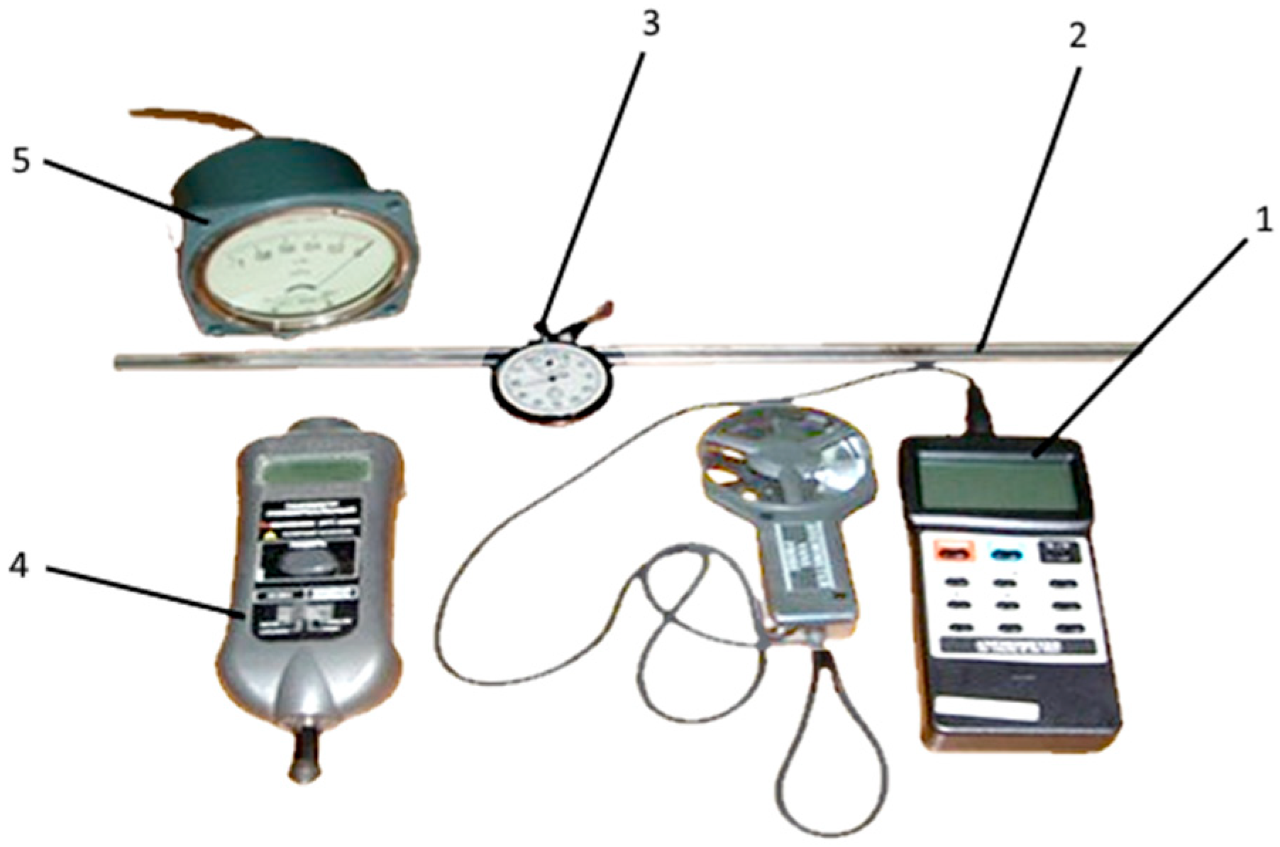
The instruments used (Figure 2) are part of the facilities of our Sprayer Testing Laboratory and have undergone regulatory calibration and verification.
To measure the speed V [m/s] of the air flow at the plant crown entry, an electronic anemometer 1 model ATT-1005 (manufacturer Joint Stock Company “ELICS Production and Research Enterprise”, Moscow, Russia) was used, with a measurement error Δlim = ±0.05 m/s. The hydraulic pressure p [Pa] was measured using a Pitot tube Prandtl model (manufacturer Testo SE & Co KGaA, Baden-Württemberg, Germany). The duration of each experiment was set using chronometer 3 model SOPpr-2A-3-000 (manufacturer Zlatoust Watch Factory, Zlatoust, Russia).
A laser tachometer 4 model ATT-6006 (manufacturer Lutron Electronic Enterprise Co., Ltd., Taipei city, Taiwan) was used to measure the fan rotor speed. Pressure meter with 5 pulses model TmMP-100U3 (manufacturer TD “Machine and Instrument Factory “Saransk” LLC, Saransk, Russia) allowed for the measurement of the vacuum in the droplet collection chamber.
The experiments were conducted randomly in three repetitions. The calculation of regression coefficients, variance analysis, model fit, and graphs were made using the “STATGRAPHICS Plus 5.1” program. The statistical processing of the measurement results was carried out in Excel 2021 (Microsoft Corporation, Redmond, WA, USA).
The electric motor from stand 1 was started, driving the rotor of fan 2 (Figure 1). The air was directed into the distribution hose 3, from which it exited in a controlled flow through the holes 4. Pump 5 was then activated, ensuring the circulation of the working solution from tank 6 to the pressure regulator 7, which was equipped with pressure gauge 8 and control valve 9. Subsequently, the working solution was pumped through the hydraulic pipe 10 and into the spraying nozzles 11, which atomized and directed it toward the bush 12. A portion of the working solution that did not deposit on the foliar apparatus entered the collection chamber 13 and drained along its inner walls into the collection vessel 14. To generate a vacuum in the droplet collection chamber 13, fan 16 was activated, transmitting the suction effect through pneumatic hoses 15 toward the collection chamber 13. Each experiment lasted one minute, after which both air and working solution flows were stopped. The working solution collected in vessel 14 was then poured into a graduated cylinder for volume measurement. The required hydraulic pressure was adjusted via pressure regulator 7. The necessary airflow, conveyed through distribution hoses 3, was achieved by regulating the rotational speed of fan rotor 2, through adjustments of the drive parameters on the KI 5342.1 stand (manufacturer: GOSNITI Institute, Moscow, Russia). Airflow was monitored using a Pitot tube and the TmMP-100U pressure gauge (Saransk, Russia), (Figure 2), following established procedures [8,36]. The airflow rate in collection chamber 13, required for the experiments, was adjusted by modifying the position of flap 17 and monitored using the electronic anemometer ATT-1005 (Moscow, Russia).
Two imitation bushes 12 were prepared, identical in volume, but differing in the number of leaves. Each bush consisted of two horizontally stretched wires on the stand, to which fresh grapevine branches with leaves were attached, with a volume of 0.5 m3.
During multifactorial research, the temperature of the working solution (water) and the ambient temperature in the laboratory were 20 ± 2 °C.

2.2. Field Testing

We aimed to determine the recovery rate of the working solution and the quality of treatment. The tests were conducted at the Experimental Technological Station “Codru”, in Chisinau, in compliance with the requirements of applicable regulations [36,37,38,39]. Test conditions are presented in Table 2.
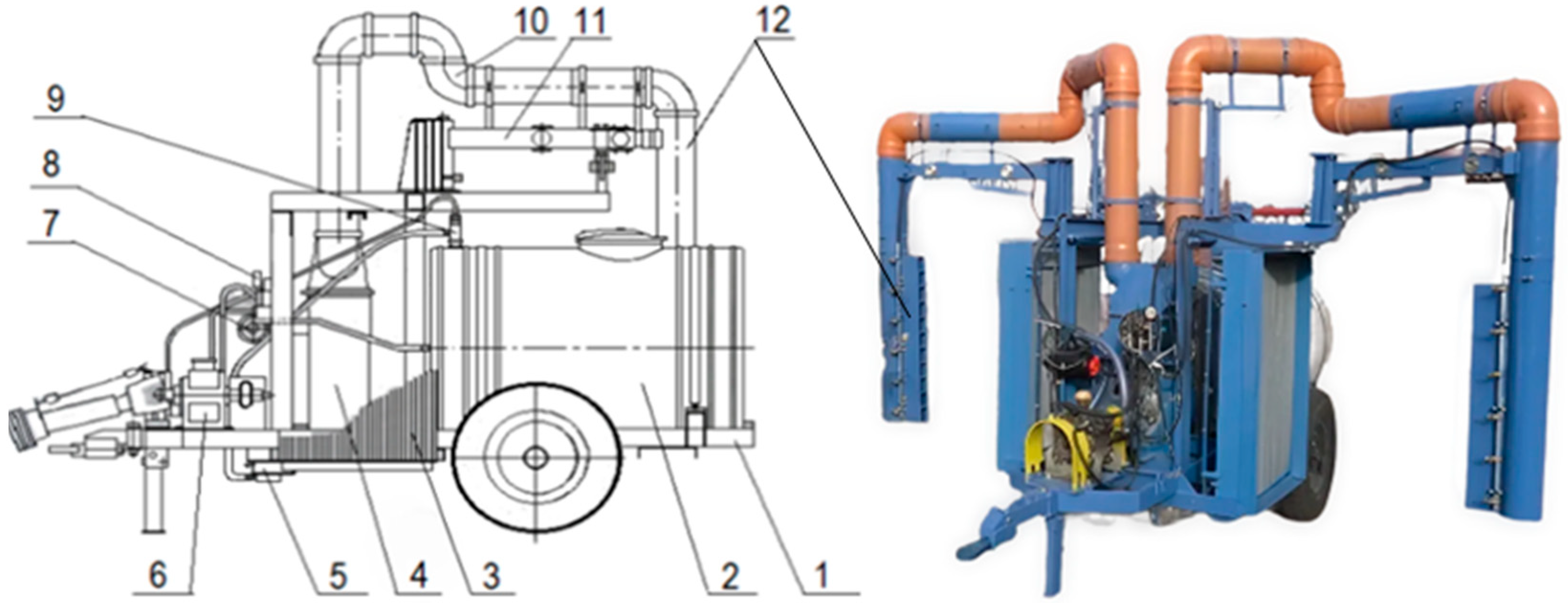
In the second phase of our research, an experimental model of the sprayer with working solution recovery was designed and manufactured (Figure 3).
During the field testing of the experimental spraying machine, the foliage coefficient of the grapevine bushes was determined. 10–20 leaves were collected from different regions of each plant’s canopy, including the upper, middle, lower, and peripheral regions.
The total mass of the selected leaves was measured using a scale. Then, with a sharp-edged metal tube, a section with a diameter of Φ13 mm was taken from the middle part of each leaf. The collected sections were weighed. Based on the mass of the collected leaves, the mass and surface area of the sections taken from the leaves, the foliage coefficient (K0) for an area of 1 ha was calculated using the equation [36,40]:
K 0 = 10 8 S b × C l × F × B c G b
where: Sb is the surface area of the section [cm2]; Cl is the mass of collected leaves [g]; Gb is the mass of the sections in the leaves [g]; F is the average number of leaves per plant [pcs.]; Bc is the number of plants [pcs/ha].
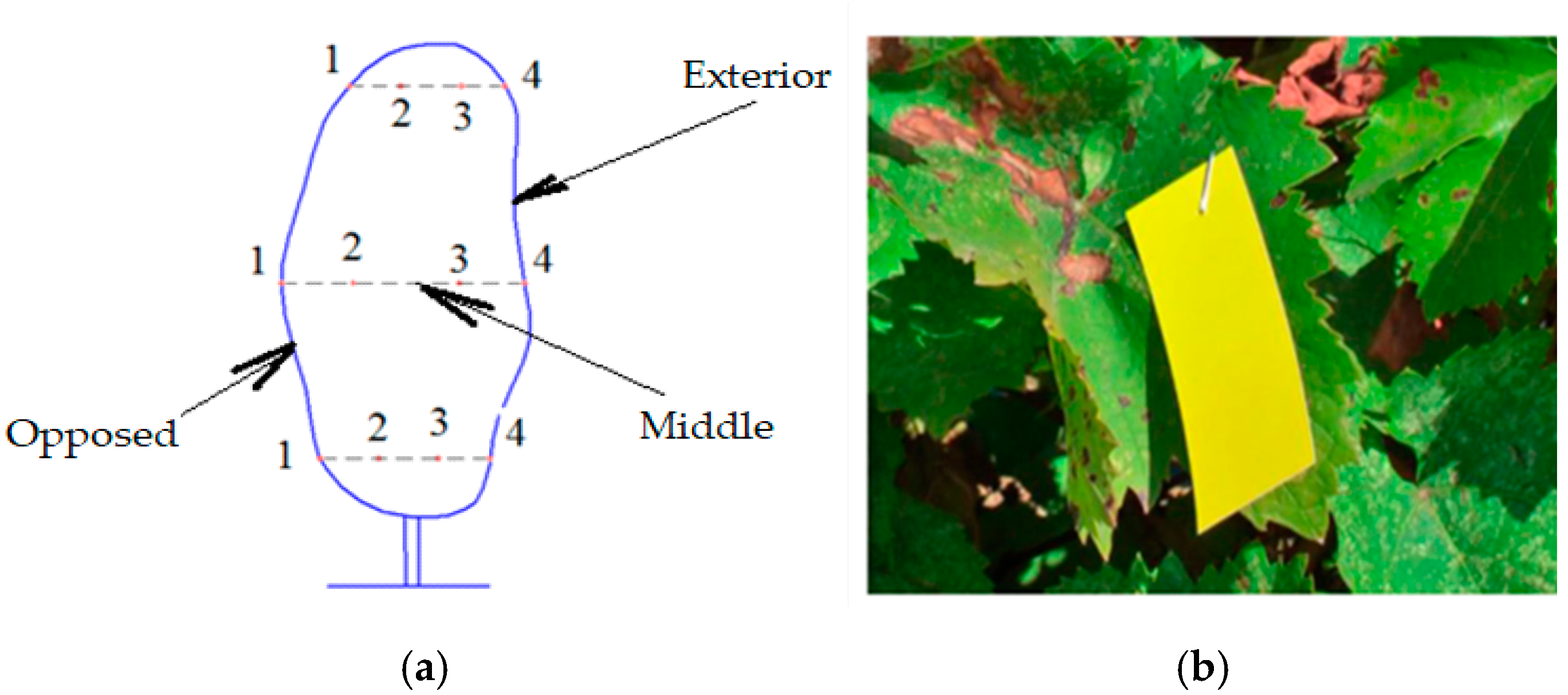
The dimensions of the bush were determined using a measuring tape (Topmaster model 260556, 5 m, Moscow, Russia). To determine the recovery rate of the working solution, plant rows were treated with clean water. The amount of working solution (1400 L) from the sprayer tank was sprayed as follows: 700 L with working solution recovery; 700 L without working solution recovery. To assess treatment quality, water-sensitive papers (manufacturer LEHLER, Metzingen, Germany) were placed in the grapevine crowns according to the following scheme: 12 cards in three zones of the crown (exterior, middle, and opposite) at three levels (upper, middle, and lower). In each area, 4 cards were clipped onto the plant leaves using staples, as shown in Figure 4.
After the treatment was performed, the water-sensitive papers were collected and sorted based on the degree of coverage with dispersed working solution droplets. The cards were then scanned and processed on the computer using specialized RO software (Drop Vision AG, LeafLab v.3.2, Germany).

3. Results

According to the Box-Behnken planning matrix (Table 1), 27 experiments were performed, with the results presented in Table 3.
After processing the data using “Statgraphics” software (Statgraphics Centurion XVI), a detailed analysis of the experimental results was conducted, including the effects of independent variables (X1, X2, X3, X4), their interactions, and optimization of the dependent variable response Y [%] was made.
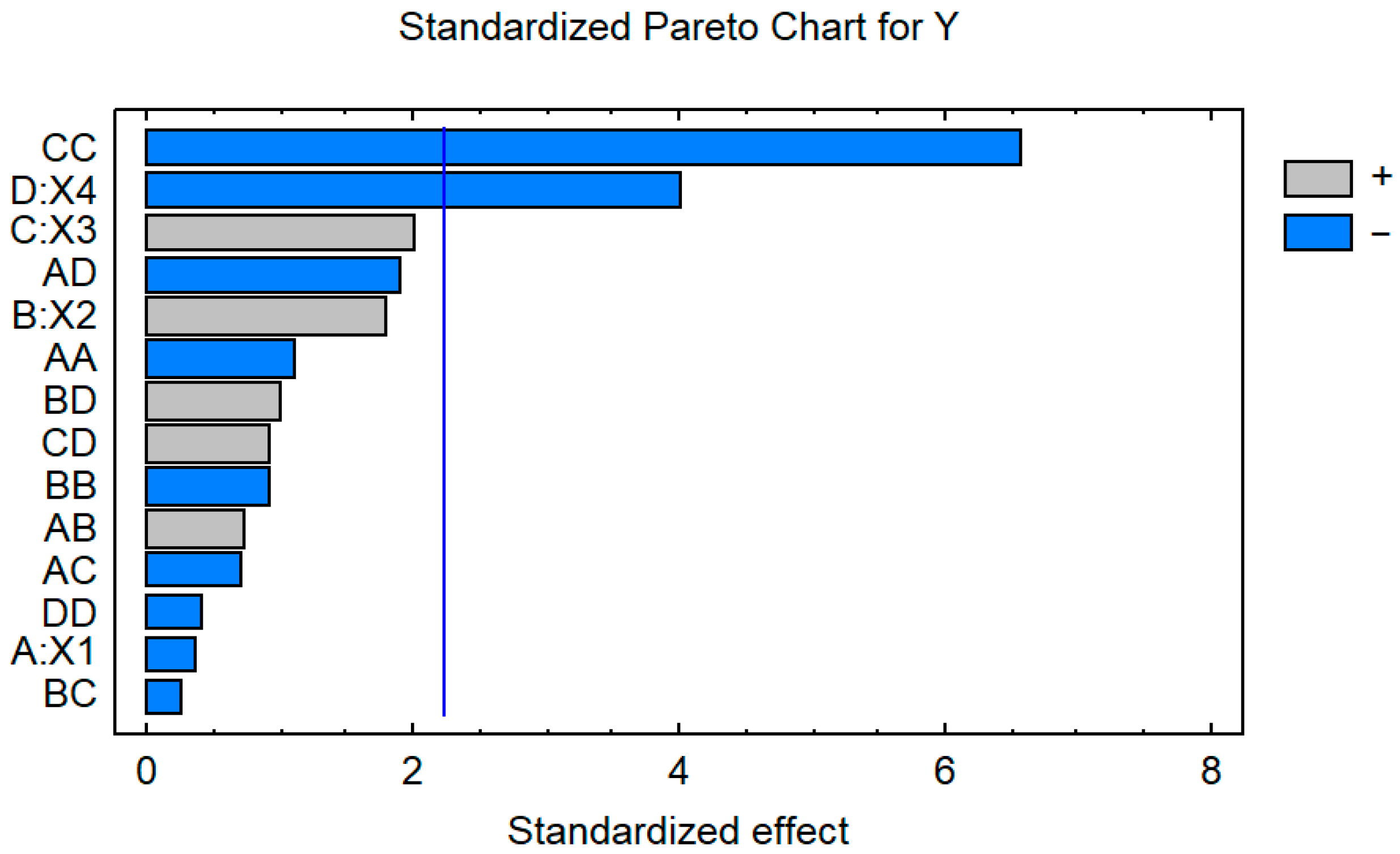
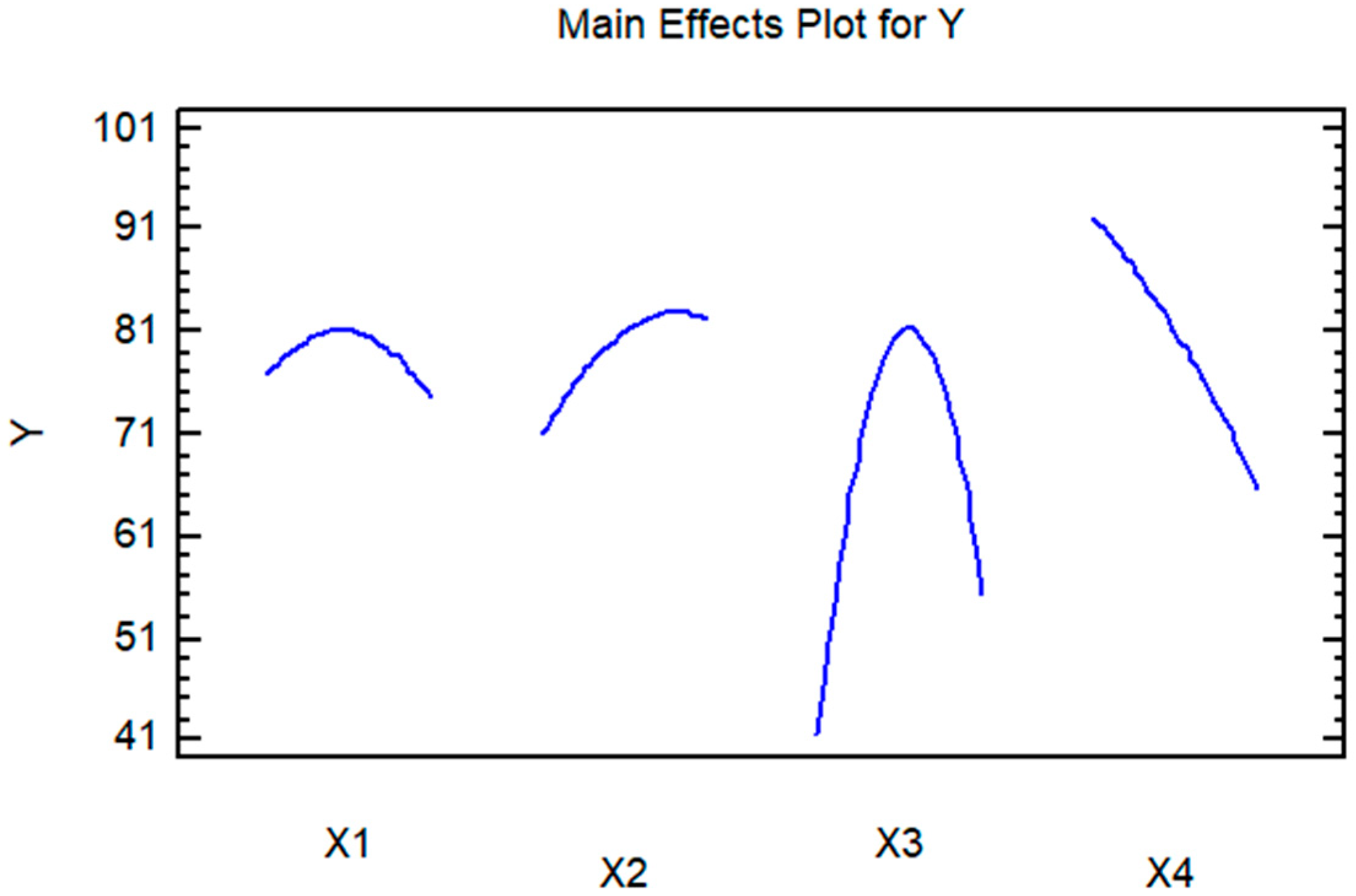
The influence of the X4 variable is the most significant (K = −26.6071). Among second-degree variables, factor X32 has a significant contribution, as does the negative meaning (−65.5415) (Table 4, Figure 5). The Variance Inflation Factor (VIF) values are small (<10), which indicates the lack of strong collinearity between variables.
The statistical significance of each effect, by comparing the mean square with an estimate of experimental error and R2 statistic, is presented in Table 5.
Based on the experimental data (Table 3), the validity range was estimated, with the following indicators: coefficient of determination R2 = 89.2458%; coefficient of determination R2 (adjusted for degrees of freedom df) = 76.6992%; standard error of estimate = 10.9454; mean absolute error = 5.65002; Durbin-Watson statistic = 2.13289 (p = 0.4609); residual autocorrelation Lag 1 = −0.162775.
Table 5 shows the following:
  • Two effects (factors) are statistically significant (p < 0.05): X4 (p = 0.0026) and X32 (p = 0.0001).
  • Since the p-value is greater than 5.0%, there is no indication of serial autocorrelation in the residuals at the 5.0% significance level.
  • The obtained mathematical model (3) explains 89.25% of the variability in the response variable Y (coefficient of determination R2).
After analyzing the experimental data, the regression equation was derived to accurately represent the relationship between the recovery rate (Y) of the working solution and the influencing factors:
Y = 81.0 − 1.09969·X1 + 5.71279·X2 + 6.78272·X3 − 13.3036·X4 − 5.42044·X12 + 4.58928·X1·X2
− 3.93744·X1·X3 − 10.9509·X1·X4 − 4.38915·X22 − 1.31256·X2·X3 + 5.63836·X2·X4
− 32.7708·X32 +5.0·X3·X4 − 2.00297·X42
The graphs in Figure 6 complement the information obtained from the ANOVA analysis (Table 5), providing an intuitive visualization of the effects of the factors, namely:
  • Factor X4: The line Y = f(X4) has the steepest slope, confirming that X4 has a significant impact on Y, as also indicated by ANOVA.
  • Factor X3 also significantly influences Y, but with a less steep slope than X4. The dependence Y = f(X3) is presented by a line with a pronounced curvilinear character, which coincides with the Pareto chart data (Figure 5).
  • Factors X1 and X2: The lines Y = f (X1,X2) is almost horizontal, suggesting a minimal effect on Y.
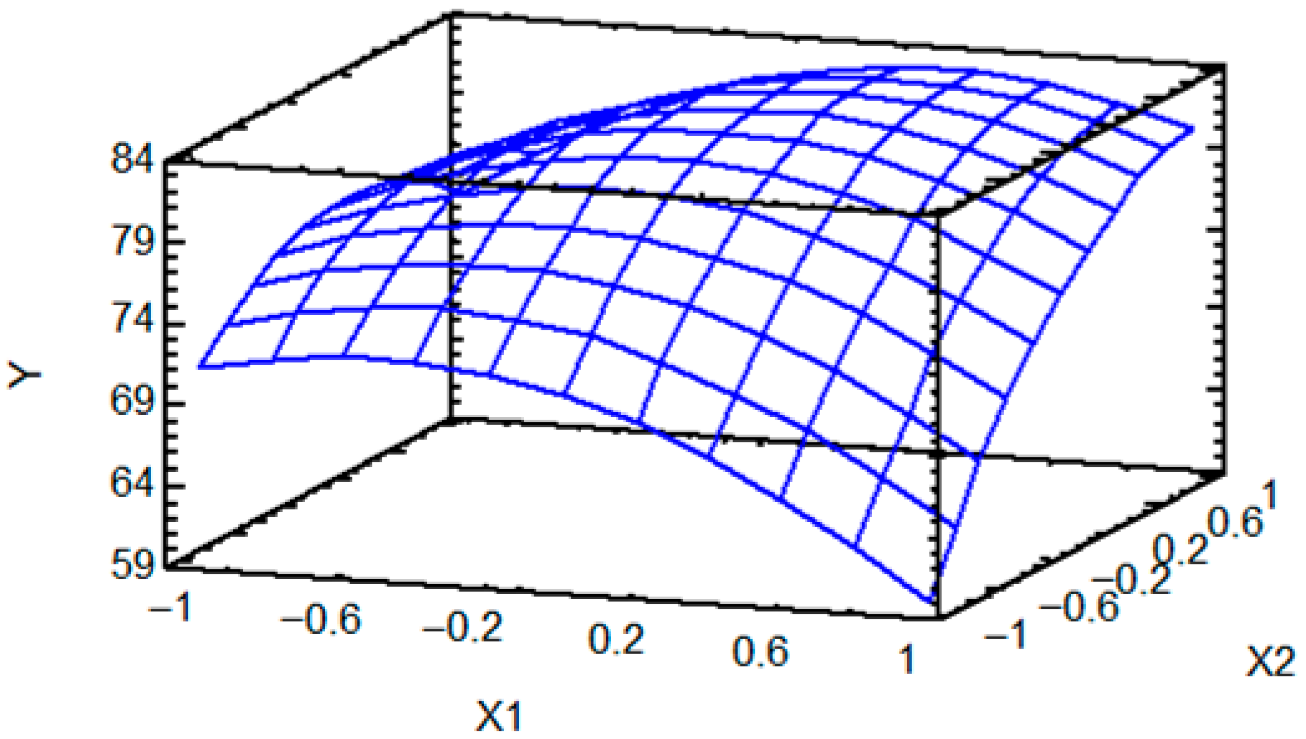
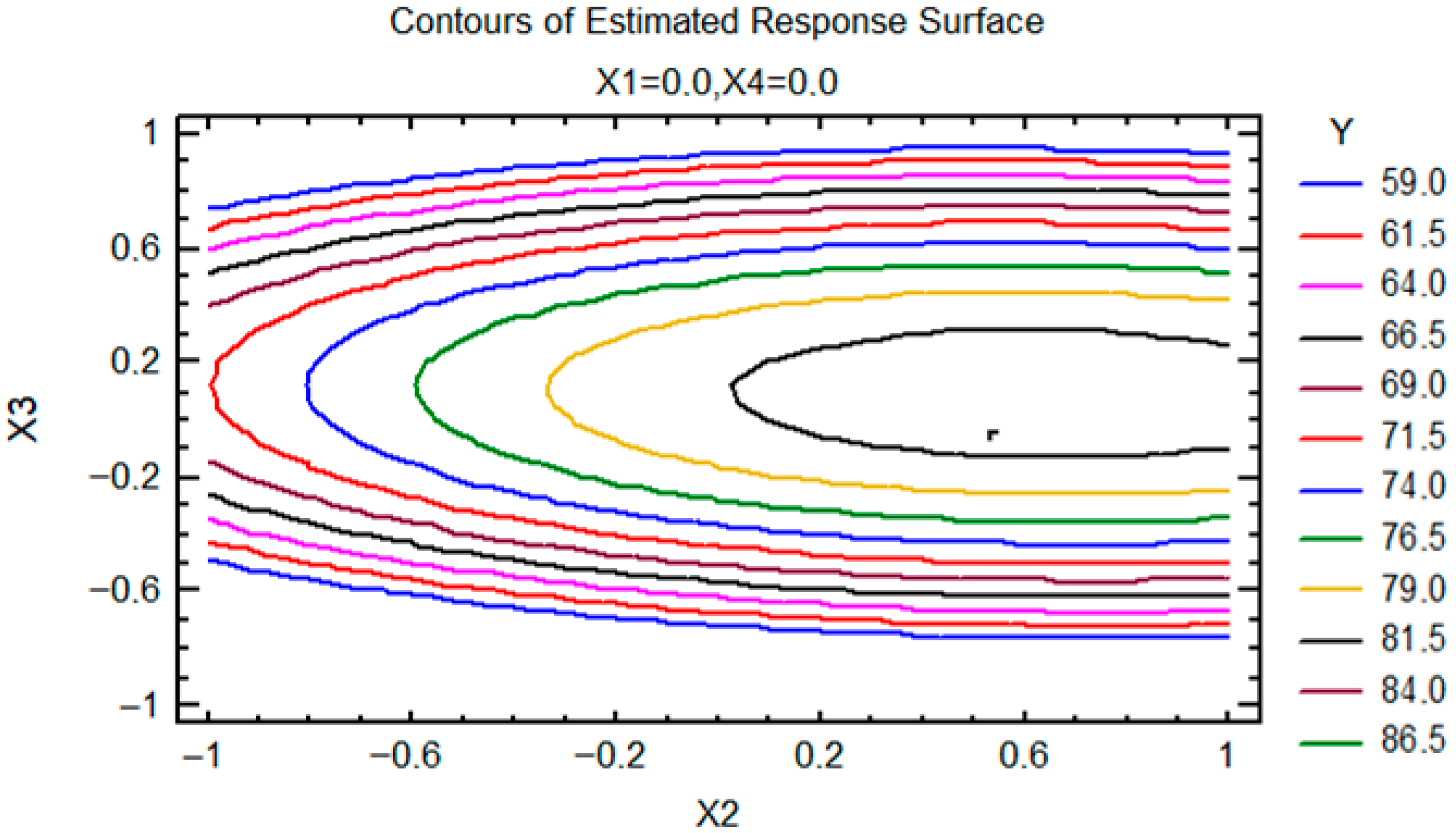
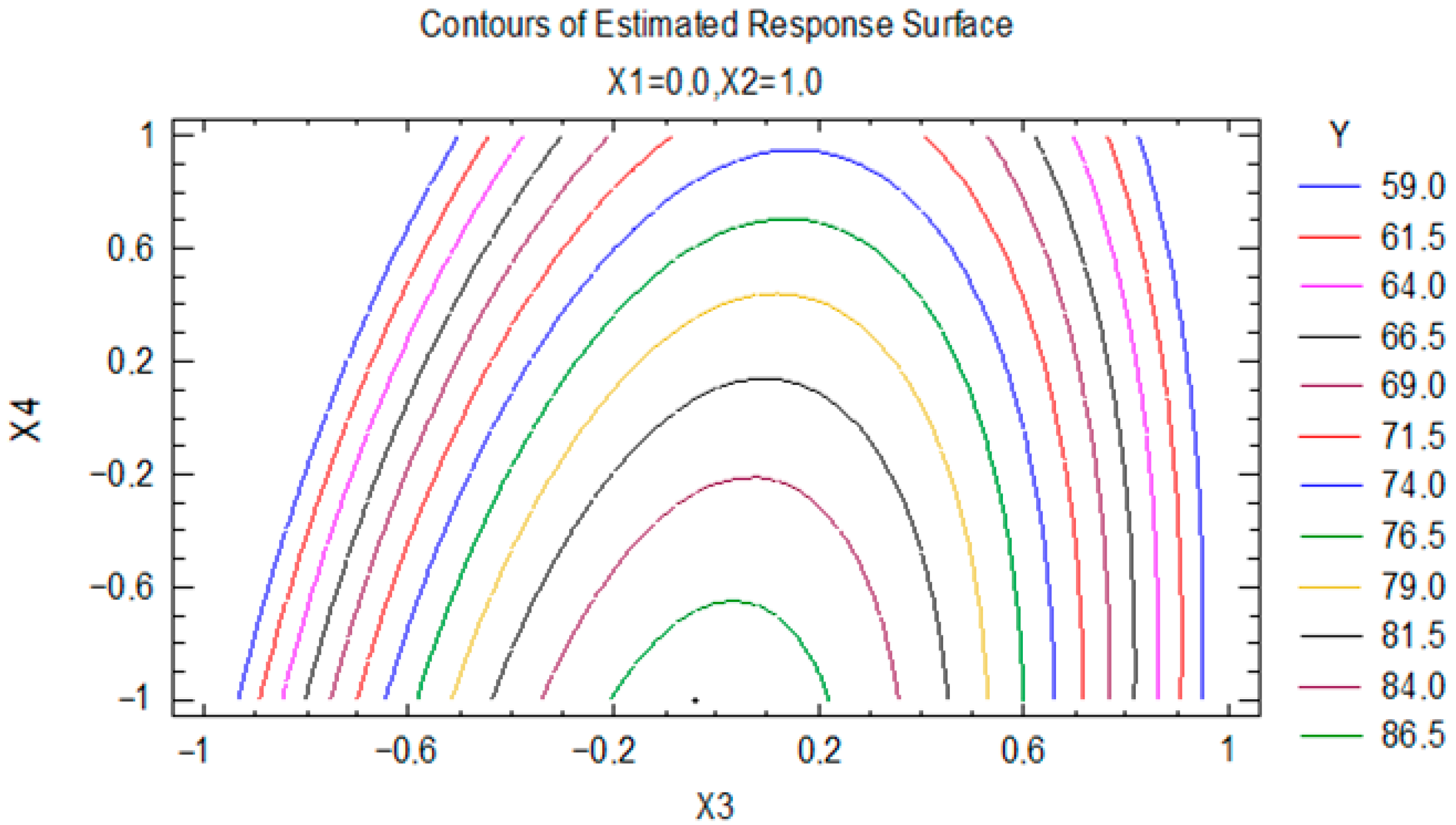
To illustrate the variation of the response variable (Y) with changes in the independent factors (X1 and X2), while maintaining the most influential factors (X3 and X4) at their average values, a response surface graph was generated, as shown in Figure 7. Additionally, cross-sectional graphs of the response surface are presented in Figure 8, Figure 9, Figure 10 and Figure 11.
The optimization of the influencing factors was performed with the aim of maximizing the response value Y, specifically the recovery rate of the working solution. As a result, the optimal levels of the influencing factors are as follows:
  • X1 = 0.999999 or, in natural value, the optimal hydraulic pressure, x1 = 25 [bar].
  • X2 = 0.534786, the optimal air flow speed at the plant crown entry, x2 = 15.1 [m/s].
  • X3 = −0.0435871, the optimal surface area of the diffuser’s central orifice, x3 = 1.2 [mm2].
  • X4 = −1.0, plant foliage density, x4 = 0 [%].
This research results demonstrate that when the optimal values of influencing factors X1, X2, X3, X4 are ensured, the maximum recovery rate can be achieved, which is Y = 98.0325%. Importantly, when the plant foliage density is equal to 0, the deviation rate of the working solution is minimal, amounting to 1.97% due to small dispersed and evaporated particles in the air, which cannot be captured. Among the four factors studied, factor X4 (plant foliage density [%]) cannot be adjusted under real operating conditions of the spraying machine, as it depends on the growth stage of grapevine bushes. However, it is essential to consider the actual foliage density value when setting the values of X1, X2, X3 to achieve the highest possible recovery rate of the working solution.
The results of the experimental research enabled the identification of the optimal values for the technological factors (X1, X2) and constructive factor (X3), proceeding to the next stage of field testing.
Field testing. The results of SVE 1500 sprayer testing under field conditions. Environmental conditions during field testing: Wind speed—4.1 m/s, ambient air temperature—24 °C, air humidity—62%. These parameters comply with the ISO 5682-1: 2017 standard [41,42]. The results of the tests are presented in Table 6.
It is important to note that the results of the preliminary measurements for evaluating the agrotechnical characteristics of grapevine bushes (Table 2) showed that the treated plants were in the active vegetation phase and berry ripening, with a foliage coefficient of 0.37. Under these conditions, the values of the working solution hydraulic pressure were increased to 30 bars and the air flow velocity to 15.5 m/s, while the diffuser’s central orifice surface area remained at the optimal level of x3 = 1.2 mm2.
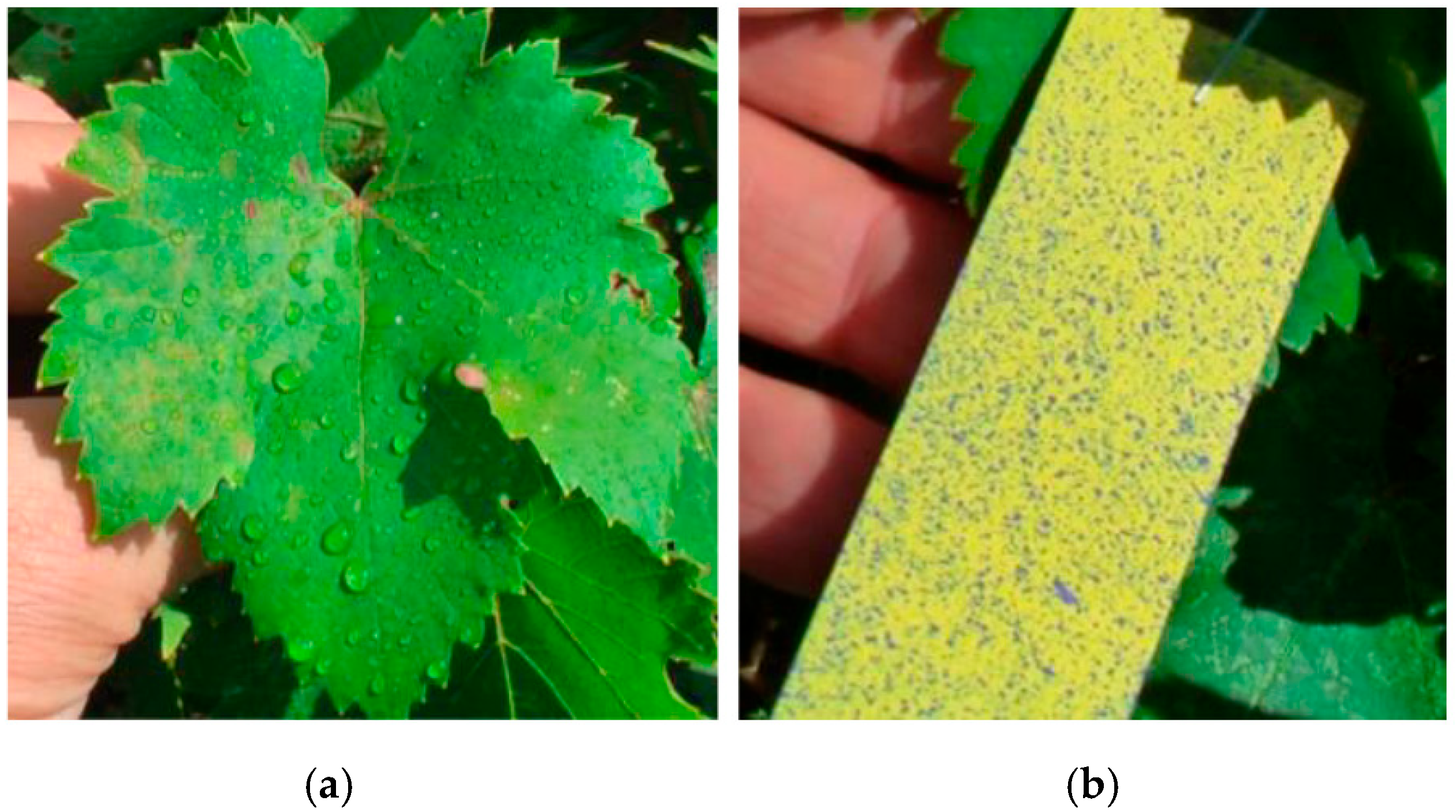
Under real testing conditions of the SVE 1500 sprayer (Table 2 and Table 6) the treatment quality was assessed using water-sensitive papers (Figure 12).
The analysis of the SVE 1500 sprayer work quality indices demonstrates that the treatment quality in field tests complies with the requirements of normative documents [10,34,35,36,37]. The above-mentioned indices have the following values:
  • Distribution of the coverage density ρ over the working width: >150 drops/cm2 ρ = 0 [%]; 150 drops/cm2 ρ = 0 [%]; <150 drops/cm 2, ρ = 100 [%]. Therefore, over the entire studied surface the density ρ (number of drops per 1 cm2) did not exceed the value of 150 drops/cm2.
  • Median diameter of the masked droplet fraction dm = 1560.0 [µm]; of the medium droplet fraction dm = 224.0 [µm]; of the small droplet fraction dm = 93.8 [µm].
  • The weighted average diameter of the droplets was D = 970 µm.

4. Discussion

Considering the values of the coefficients of the mathematical model (3), the data from the Pareto diagram (Figure 5) and the ANOVA analysis (Table 5), it can be noted that the most significant factors are X4 (plant foliage density) and X32 (central orifice area of the diffuser), which have a major influence on the working solution recovery rate. This is evident from both ANOVA (p < 0.05), and the Pareto chart and Main Effects Plot.
The difference between the two factors X4 and X32 lies in their mode of action on the recovery process. Specifically, as the value of factor X3 increases, the recovery rate rises from 41% to 81% when x3 = 1.2 mm2, but with a further increase in X3, the recovery rate Y decreases to 53% (Figure 6, Figure 9, Figure 10 and Figure 11). Increasing X4 in the range of 0–100% results in a continuous decline in the recovery rate from 98% to 59% (Figure 6, Figure 10 and Figure 11).
Non-significant variables X1 (working solution hydraulic pressure) and X2 (air flow velocity at plant crown entry) do not have a significant impact on Y (p > 0.05) (Table 5).
The performance analysis of the obtained mathematical model demonstrates a high-quality fit: the model has a high R2 (89.25%), which explains most of the variation in Y. However, the adjusted R2 (76.70%) is significantly lower, suggesting that some factors included in the model may not significantly contribute to explaining the variation.
Regarding the validity and limitations of the analysis based on the mathematical model (3), the low VIF values (<3) confirm that the independent variables are relatively orthogonal, supporting the validity of the coefficient estimates. The Durbin-Watson test does not indicate significant autocorrelation, confirming the independence of observations.
The practical interpretation and applications of the analysis based on the obtained mathematical model identify the optimal levels of the factors (X1 = 0.999999, X2 = 0.534786, X3 = −0.0435871, X4 = −1) that lead to an estimated response value of Y = 98.0325%. This result provides a solid foundation for practical applications.
Researchers from Romania [15] established that increasing the working solution pressure within the range p = 10–25 bar causes a decrease in the working solution recovery rate from 20.3% to 7.61%. In this case, varying the working solution pressure within the range p = 15–25 bar, results in achieving maximum recovery values at a pressure of p = 20–25 bar.
According to information from manufacturers of sprayers with working solution recovery [12,13,20,26,27,43,44,45] their machines ensure a reduction in pesticide consumption of 10–80% compared to conventional treatment, depending on the plant growth stage, and mitigate the negative environmental impact of pesticides. During field testing of the SVE 1500 spraying machine, a reduction in the specific working solution consumption by 38% was achieved, with vine bushes in the active vegetation and fruit maturation stage (foliage coefficient Kf = 0.37).
The field tests of the SVE 1500 spraying machine revealed that its structural design enables it to be towed with an adequate turning radius, making it suitable for operation in modern vineyards. The data obtained in this study suggest promising directions for the development of viticultural sprayers with working solution recovery. Capture devices with sedimentary labyrinths ensure the recovery of very fine droplets (under 90 microns) into the tank, preventing their entrainment by the airflow.

5. Conclusions

This research found that the most significant factors influencing the working solution recovery rate are the area of the central orifice of the diffuser X3 [mm2]; foliage density X4 [%].
The use of capture devices with sedimentary labyrinths has proven effective in ensuring the recovery of very fine droplets (under 90 microns). This process prevents working solution loss caused by airflow entrainment, thereby enhancing operational efficiency and minimizing the negative environmental impact.
Field testing of the SVE-1500 sprayer demonstrated that working solution recovery ensures an absolute economy of 431 L/ha (38%) compared to the method without recovery. Evaluation of treatment quality indices showed a uniform distribution of coverage density across the working width, with a well-distributed average droplet diameter. The smallest droplets (under 90 microns) were effectively captured, contributing to the overall performance of the sprayer.
The results indicate promising directions for further development of sprayers. Integrating capture devices with sedimentary labyrinths can increase the efficiency and sustainability of the process, reducing chemical losses and mitigating the environmental impact. These conclusions highlight the importance of optimizing the technical parameters and using innovative devices in spraying processes.

6. Patents

Short-term patent. 272 Y, MD, A 01 M 7/00. Spraying machine with recovery/Ion Hăbăşescu, Valerian Cerempei, Boris Chicu, Sergiu Vasilevschi, Galina Lungu, Vladimir Cobernic (MD). Application submitted on 15.02.2010, BOPI no. 9/2010.
Short-term patent. 397 Y, MD, A 01 M 7/00. Cyclone spraying machine/Ion Hăbăşescu, Valerian Cerempei, Boris Chicu, Sergiu Vasilevschi, Galina Lungu, Vladimir Cobernic, Ilarion Bragari (MD). Application submitted on 22.12.2010, BOPI no. 7/2011.

Author Contributions

Conceptualization, I.P., V.C. and N.-V.V.; methodology, I.P., B.C. and V.C.; software, V.C., N.-V.V. and N.U.; validation, I.P., B.C. and V.C.; formal analysis, I.P., V.C. and N.-V.V.; investigation, I.P., V.C. and N.-V.V.; resources, V.C., N.-V.V., N.-E.G. and N.U.; data cleaning, N.-V.V. and N.U.; written—original draft preparation, I.P., V.C., N.-V.V. and N.U.; writing—review and editing, I.P., N.-V.V., N.U. and N.-E.G.; visualization, I.P., B.C. and V.C.; supervision, I.P. and N.-V.V.; funding acquisition, N.-E.G. All authors have read and agreed to the published version of the manuscript.

Funding

The APC was funded by the National University of Science and Technology Politehnica Bucharest, Romania, within the PubArt Program.

Institutional Review Board Statement

Not applicable.

Informed Consent Statement

Not applicable.

Data Availability Statement

The data presented in this study are available on request from the corresponding authors.

Conflicts of Interest

The authors declare no conflicts of interest. The funder had no role in the study design, data collection, analysis, or interpretation, manuscript writing, or decision to publish the results.

References

  1. Food and Agriculture Organization of the United Nations (FAO). The State of Food and Agriculture: Climate Change, Agriculture and Food Security; FAO: Rome, Italy, 2016; 194p, ISBN 978-92-5-109374-0. ISSN 0081-4539. Available online: http://www.fao.org/3/a-i6030e.pdf (accessed on 15 June 2025).
  2. Blanco, H.; Lal, R. Soil Conservation and Management, 2nd ed.; Springer: Berlin/Heidelberg, Germany, 2023; 611p, ISBN 978-3-031-30340-1/978-3-031-30341-8. [Google Scholar] [CrossRef]
  3. Bojariu, R.; Hurmuzachi, I. Guide to Good Practices in Adapting to Climate Change and Implementing Climate Change Mitigation Measures in the Agricultural Sector; Print-Caro: Chișinău, Moldova; UCIP IFAD: Chișinău, Moldova, 2021; 120p, ISBN 978-9975-5. Available online: https://www.ucipifad.md/wp-content/uploads/2020/07/Ghid-de-bune-practici-pentru-sectorul-agricol-intru-adaptarea-la-schimbarile-climatice_pag-1-40.pdf (accessed on 13 March 2025). (In Romanian)
  4. Vlăduț, N.V.; Atanasov, A.; Ungureanu, N.; Ivașcu, L.V.; Cioca, L.I.; Popa, L.D.; Matei, G.; Boruz, S.; Cerempei, V.; Țîței, V.; et al. Trends in the development of conservative/ecological agriculture in the context of current climate change—A review. INMATEH-Agric. Eng. 2024, 74, 980–1032. [Google Scholar] [CrossRef]
  5. Visconti, F.; López, R.; Olego, M.Á. The health of vineyard soils: Towards a sustainable viticulture. Horticulturae 2024, 10, 154. [Google Scholar] [CrossRef]
  6. Gristina, L.; Novara, A.; Minacapilli, M. Rethinking vineyard ground management to counter soil tillage erosion. Soil Tillage Res. 2022, 217, 105275. [Google Scholar] [CrossRef]
  7. Cataldo, E.; Fucile, M.; Mattii, G.B. A review: Soil management, sustainable strategies and approaches to improve the quality of modern viticulture. Agronomy 2021, 11, 2359. [Google Scholar] [CrossRef]
  8. Molnar, I.; Keicher, R.; Schwartz, H.P. Sprayer development for vineyards. UPB. Sci. Bull. 2018, 80, 281–292. [Google Scholar]
  9. Chicu, B.; Lungu, G.; Vasilevschi, S.; Cerempei, V.; Cobernic, V.; Prisacari, V.; Bragari, I. Plant Protection: Technologies and Technical Means; Bons Offices: Chișinău, Moldova, 2010; 312p, ISBN 978-9975-80-418-9. (In Romanian) [Google Scholar]
  10. European Parliament and Council of the European Union. Directive 2009/127/EC Amending Directive 2006/42/EC with Regard to Machinery for Pesticide Application. Available online: https://eur-lex.europa.eu (accessed on 1 September 2024).
  11. Facchinetti, D. Atomizers with Product Recovery: An Eco-Friendly Solution (Gli Atomizzatori con Recupero del Prodotto, una Soluzione Ecologica). In MW-Machinery World. 2017. Available online: https://www.mondomacchina.it/it/gli-atomizzatori-con-recupero-del-prodotto-una-soluzione-ecologica-c1927 (accessed on 3 June 2025). (In Romanian).
  12. Bertoni Green Technology. Irroratrice a Tunnel Modello TR. Available online: https://www.bertonigreentechnology.com (accessed on 13 March 2025).
  13. Lipco GmbH. Sprühgeräte Zum Versrühen Von Pflanzenschutzmittel. Available online: https://www.lipco.com (accessed on 13 June 2025).
  14. Chirilă, C.; Vâlcu, V. Preliminary Tests in real working conditions of the recovery panels for spraying solution mounted on V-445 tractor. In Horticultura; University of Agricultural Sciences and Veterinary Medicine: Iași, Romania, 2006; Volume 49. [Google Scholar]
  15. Hăbăşescu, I.; Cerempei, V.; Chicu, B.; Vasilevschi, S.; Lungu, G.; Cobernic, V. Spraying Machine with Recovery. Short-Term Patent MD 272 Y, A 01 M 7/00, BOPI No.9/2010. Available online: https://agepi.gov.md/sites/default/files/bopi/BOPI_09_2010.pdf (accessed on 23 September 2025). (In Romanian).
  16. Hăbăşescu, I.; Cerempei, V.; Chicu, B.; Vasilevschi, S.; Lungu, G.; Cobernic, V.; Bragari, I. Cyclone Spraying Machine. Short-Term Patent MD 397 Y, A 01 M 7/00. Available online: https://agepi.gov.md/sites/default/files/bopi/BOPI_07_2011.pdf (accessed on 23 September 2025). (In Romanian).
  17. Marin, E.; Gheorghe, G.V.; Bălțatu, C.; Mateescu, M. Application of 3D printing technology for the design and manufacture of some component parts of spraying machine with solution recovery. INMATEH-Agric. Eng. 2022, 67, 147–154. [Google Scholar] [CrossRef]
  18. Matache, M.G.; Marin, F.B.; Gurău, C.; Gurău, G.; Marin, M.; Găgeanu, I.; Ionescu, A. Neural network testing for spot-application of phytosanitary substances in vegetable crops using a self-propelled electrical sprayer. INMATEH-Agric. Eng. 2022, 68, 471–480. [Google Scholar] [CrossRef]
  19. Bungescu, S.; Caba, I.; Duma Copcea, A.; Popa, D.; Salanki, R.; Giurgiu, C.; Melneciuc, C.; Valer, P. In-Depth Experimental Research regarding the verification of spraying machines in large culture farms in the Western area of Romania. In Proceedings of the International Symposium ISB INMATEH, Bucharest, Romania, 15 October 2021. [Google Scholar]
  20. Wimmer, A. Fachkunde: Land-Und Baumaschinentechnik; Verlag Europa-Lehrmittel: Hamburg, Germany, 2016; 575p, ISBN 978-3-8085-2007-9. Available online: www.europa-lehrmittel.de (accessed on 3 July 2025).
  21. Neacșu, F. Ecoprotect L3, a New Gregoire equipment for Phytosanitary Treatments in Vineyards (Ecoprotect L3, un nou Echipament Gregoire Pentru Tratamente Fitosanitare în Podgorii). Ferma, 2 July 2020. Available online: https://revista-ferma.ro/ecoprotect-l3-un-nou-echipament-gregoire-pentru-tratamente-fitosanitare-in-vii/ (accessed on 3 July 2025). (In Romanian)
  22. Idealitalia. Recovery Sprayers. Available online: https://www.idealitalia.it (accessed on 5 July 2025).
  23. Coffee. Recovery Sprayers. Available online: https://www.caffini.com (accessed on 5 July 2025).
  24. Ciclone SRL. Recovery Systems for Sprayers for Pesticides and Vineyards. Available online: https://www.ciclonesrl.it (accessed on 3 July 2025).
  25. Carraro Spray. Gli Atomizzatori Amici Dell’ambiente. Available online: https://www.carrarospray.com (accessed on 3 August 2024).
  26. Favaro. Drift Recovery Sprayer. Available online: https://www.favaro.eu (accessed on 2 July 2025).
  27. VitiBot Confined Spraying. Available online: https://vitibot.fr (accessed on 23 September 2025).
  28. Pergher, G.; Gubiani, R. The effect of spray application rate and air assistance on spray deposition in vineyards. Crop Prot. 1995, 14, 343–347. [Google Scholar]
  29. Balsari, P.; Marucco, P.; Tamagnone, M. A field study on tunnel sprayers in vineyards. Crop Prot. 2001, 20, 405–412. [Google Scholar]
  30. Planas, S.; Gallart, M.; Fillat, A. Evaluation of recycling tunnel sprayers in orchards. J. Agric. Eng. Res. 2002, 83, 79–88. [Google Scholar]
  31. Interstate Standard GOST MD 53053-2008; Plant Protection Machines. Spraying Machines. Test Methods. National Standard of The Russian Federation: Moscow, Russia, 2009. Available online: https://meganorm.ru/Data2/1/4293831/4293831096.htm (accessed on 10 July 2025). (In Russian)
  32. Testing of Agricultural Machinery. Sprayers, Pollinators, Entomophagous Dispersers, Machines for the Treatment and Transport of Working Fluid. Test Program and Methods. RD 10 6.1-89. Moscow. 2009. 35p. Available online: https://meganorm.ru/list2/64490-0.htm (accessed on 10 July 2025).
  33. Mencher, É.M.; Zemșman, A.Y. Basics of Experimental Planning with Elements of Mathematical Statistics in Viticultural Research; Știința Publishing House: Chișinău, Moldova, 1986; 240p. (In Russian) [Google Scholar]
  34. Montgomery, D.C. Design and Analysis of Experiments, 8th ed.; John Wiley & Sons: Hoboken, NJ, USA, 2013; 757p, ISBN 978-1-118-14692-7. Available online: https://www.slideshare.net/slideshow/douglas-c-montgomery-design-and-analysis-of-experimentswiley-2013pdf/265094162 (accessed on 8 July 2025).
  35. Ferreira, S.L.C.; Bruns, R.E.; Ferreira, H.S.; Matos, G.D.; David, J.M.; Brandão, G.C.; da Silva, E.G.P.; Portugal, L.A.; dos Reis, P.S.; Souza, A.S.; et al. Box-Behnken design: An alternative for the optimization of analytical methods. Anal. Chim. Acta 2007, 597, 179–186. [Google Scholar] [CrossRef] [PubMed]
  36. Şaragov, I.; Vîrlan, L. Measurement of Local Velocities in Fluid Flows: Methodological Guide; Technical University of Moldova, Faculty of Urban Planning and Architecture: Chișinău, Moldova, 2020; 48p. (In Romanian) [Google Scholar]
  37. ISO 5682-2:2017; Equipment for Crop Protection—Spraying Equipment Part 2: Test Methods to Assess the Horizontal Transverse Distribution for Hydraulic Sprayers. ISO: Geneva, Switzerland, 2017. Available online: https://www.iso.org/standard/60054.html (accessed on 23 September 2025).
  38. Stahli, W.; Bungescu, T. Devices, Equipment and Machines for Plant Protection; AgroPrint: Bucharest, Romania, 2006; 377p, ISBN (10) 973-8287-39-1/(13) 978-973-8287-39-6. (In Romanian) [Google Scholar]
  39. Directives 2023 for the Inspection of Existing Sprayers for Fruit, Winemaking and Outdoor Culture. Available online: https://www.agrartechnik.ch/fileadmin/user_upload/spritzentests/Richtlinien_Spr%C3%BChger%C3%A4te_2023_D.pdf (accessed on 3 July 2025).
  40. Lentochkin, A.M. Agronomic Research Methods: Methodological and Didactic Guide; FGBOU VO Izhevsk State Agricultural Academy: Izhevsk, Russia, 2018; 172p, Available online: http://portal.izhgsha.ru/docs/15122017_22641.pdf (accessed on 3 July 2025). (In Russian)
  41. EN ISO 16122-3:2024; Agricultural and Forestry Machinery—Inspection of Sprayers in Use—Part 3: Sprayers for Bush and Tree Crops. ISO: Geneva, Switzerland, 2024. Available online: https://www.iso.org/standard/83370.html (accessed on 23 September 2025).
  42. ISO 5682-1:2017; Equipment for Crop Protection—Spraying Equipment—Part 1: Test Methods for Sprayer nozzles. ISO: Geneva, Switzerland, 2017. Available online: https://www.iso.org/standard/60053.html (accessed on 23 September 2025).
  43. Roșu, M.; Căsăndroiu, T.; Matache, M.G.; Vlăduț, V.; Pruteanu, A. Experimental researches regarding the dispersion angle of the nozzle jet from spraying machines. UPB Sci. Bull. Ser. D Mech. Eng. 2018, 80, 207–218. [Google Scholar]
  44. Pergher, G.; Petris, R. The Effect of Air Flow Rate on Spray Deposition in a Guyot-trained Vineyard. Agric. Eng. Int. CIGR Ejournal 2008, X, 1–15. [Google Scholar]
  45. Dumitrașcu, A.; Manea, D.; Popa, R.; Popa, V.; Deak, G.; Duţă, D.; Dinu, M. Modern trends in applying phytosanitary treatments in orchards. Fruit Grow. Res. 2018, XXXIV, 83–88. [Google Scholar] [CrossRef]
Figure 1. Simplified diagram of the experimental equipment: 1—stand; 2—centrifugal fan; 3—distribution hose; 4—holes; 5—pump; 6—tank; 7—pressure regulator; 8—pressure gauge; 9—control valve; 10—pipes; 11—nozzles; 12—bush; 13—droplet collection chamber; 14—collection vessel; 15—pneumatic hose; 16—centrifugal fan; 17—flap [Authors’ own drawing].
Agriengineering 07 00326 g001
Figure 2. Instruments used during the experiments: 1—electronic anemometer (ATT-1005); 2— Pitot tube; 3—timer; 4—laser tachometer (ATT-6006); 5—pulse pressure meter (TmMP-100U3) [Authors’ own picture].
Agriengineering 07 00326 g002
Figure 3. SVE 1500 sprayer: 1—frame; 2—tank with a capacity of 1500 L; 3—lateral droplet collectors; 4—ventilation assembly equipped with an axial fan; 5—working solution recovery accumulator; 6—centrifugal pump; 7—suction (absorption) filter; 8—pressure regulator; 9—ejector; 10—pipes; 11—hydraulic cylinders; 12—nozzles [Authors’ own drawing and picture].
Agriengineering 07 00326 g003
Figure 4. Grapevine bush: (a) Placement scheme of the cards in the bush’s cross-section; (b) View of the water-sensitive papers attached to the bush foliage [Authors’ own drawing and picture].
Agriengineering 07 00326 g004
Figure 5. Pareto diagram highlighting the weight of the effects of variables and interactions on response Y.
Agriengineering 07 00326 g005
Figure 6. Influence of each independent factor on response Y, when the others factor values are maintained at their average level.
Agriengineering 07 00326 g006
Figure 7. Response surface of the recovery rate of the working solution as a function of X1 (hydraulic pressure [bar]) and X2 (air flow velocity at the plant crown entry [m/s]), for X3 = 0 and X4 = 0.
Agriengineering 07 00326 g007
Figure 8. Cross-section of the response surface of the recovery rate Y as a function of X1 and X2 for X3 = 0 and X4 = 0.
Agriengineering 07 00326 g008
Figure 9. Cross-section of the response surface of the recovery rate Y as a function of X2 and X3 for X1 = 0 and X4 = 0.
Agriengineering 07 00326 g009
Figure 10. Cross-section of the response surface of the recovery rate Y as a function of X3 and X4 for X1 = 0 and X2 = 0.
Agriengineering 07 00326 g010
Figure 11. Cross-section of the response surface of the recovery rate Y as a function of X3 and X4 for X1 = 0 and X2 = 0.5.
Agriengineering 07 00326 g011
Figure 12. Image sequences reflecting the quality of foliar treatment of grapevine bushes: (a) Treated leaf; (b) Treated card [Authors’ own picture].
Agriengineering 07 00326 g012
Table 1. Levels of influencing factors in the Box-Behnken research plan 43 (Authors’ own Table).
Influencing Factors NameNatural ValuesCoded Value Levels
LevelsVariation RangeLowerBasicHigh
LowerBasicHigh
X1—hydraulic pressure
[bar]
1520255–10+1
X2—air flow speed at the nozzle exit
[m/s]
1214162−10+1
X3—surface of the central orifice of the diffuser
[mm2]
01.252.51.25−10+1
X4—plant foliage density
[%]
05010050−10+1
Table 2. Characteristics of the treated grapevine crop.
IndicesIndices Value
varietyArcadia
Planting scheme [m]
  • -
    row spacing
3.0
  • -
    plant spacing
1.0
Bush height [m]1.5
Bush diameter [m]
  • -
    lengthwise
2.5
  • -
    widthwise
0.5
Vegetation phaseActive growth and berry ripening
Foliage coefficient0.37
Table 3. Experimental plan and results of its implementation.
No. d/oCoded ValuesNatural ValuesSpecific Amount of Working SolutionRecovery Rate of the Working Solution
ConsumedRecovered
X1X2X3X4x1
[bar]
x2
[m/s]
x3
[mm2]
x4
[%]
Y1
[L/min]
Y2
[L/min]
Y
[%]
1100125141.2510081.648.059
20−10120121.2510075.633.845
3−100−115141.25066.040.662
4100−125141.25081.670.486
5011020162.550152.092.461
6−101015142.550130.069.654
7−110015161.255066.042.064
80−10−120121.25075.670.894
9000020141.255075.661.281
10101025142.550168.081.646
110−1−10201205052.812.023
12−1−10015121.255066.051.678
13110025161.255081.661.271
14−100115141.2510066.054.082
1501−10201605052.826.450
1610−10251405057.225.244
17000020141.255075.661.281
18010120161.2510075.654.071
19−10−10151405045.618.039
2000−1−120140052.832.461
2100−112014010052.87.214
221−10025121.255081.651.663
23001−120142.50150.398.465
24000020141.255075.661.281
250−11020122.550150.363.642
26001120142.5100150.356.438
27010−120161.25075.673.297
Table 4. Estimation of effects for Y.
EffectEstimateStandard ErrorVIF
X1−2.206.431.03
X211.436.431.04
X313.576.751.14
X4−26.616.671.11
X12−10.849.921.37
X32−65.5410.001.39
Table 5. ANOVA (analysis of variance).
SourceSum of SquaresdfMean SquaresF-Ratiop-Value
X114.02114.020.120.7400
X2377.841377.843.150.1100
X3484.471484.474.040.0700
X41905.8311905.8315.910.0030
X325143.4615143.4642.930.0001
Total error1198.0310119.80
Table 6. Recovery rate of the working solution obtained after field tests (x3 = 1.2 mm2).
Treatment
Method
Operating Hydraulic Pressure x1
[bar]
Airflow Speed x2
[m/s]
Travel Speed of the Tractor-Sprayer Assembly
[km/h]
Treated Plantation Area
[ha]
Working Solution VolumeWorking Solution Economy
Absolutely
Administered
[L]
Specifically Consumed
[Lha]
[L/ha][%]
with working solution recovery3015.540.43700162743138
without working solution recovery3015.540.367002058
Disclaimer/Publisher’s Note: The statements, opinions and data contained in all publications are solely those of the individual author(s) and contributor(s) and not of MDPI and/or the editor(s). MDPI and/or the editor(s) disclaim responsibility for any injury to people or property resulting from any ideas, methods, instructions or products referred to in the content.