Abstract
Collecting real-time data on physical and chemical parameters of the soil is a prerequisite for resource-efficient and environmentally sustainable agriculture. For continuous in situ measurement of soil nutrients such as nitrate or phosphate, a lab-on-chip approach combined with wireless remote readout is promising. For this purpose, the soil solution, i.e., the water in the soil with nutrients, needs to be extracted into a microfluidic chip. Here, we present a soil-solution extraction unit based on combining a porous ceramic filter with a microfluidic channel with a 12 µL volume. The microfluidic chip was fabricated from polydimethylsiloxane, had a size of 1.7 cm × 1.7 cm × 0.6 cm, and was bonded to a glass substrate. A hydrophilic aluminum oxide ceramic with approximately 37 Vol.-% porosity and an average pore size of 1 µm was integrated at the inlet. Soil water was extracted successfully from three types of soil—silt, garden soil, and sand—by creating suction with a pump at the other end of the microfluidic channel. For garden soil, the extraction rate at approximately 15 Vol.-% soil moisture was 1.4 µL/min. The amount of extracted water was investigated for 30 min pump intervals for the three soil types at different moisture levels. For garden soil and sand, water extraction started at around 10 Vol.-% soil moisture. Silt showed the highest water-holding capacity, with water extraction starting at approximately 13 Vol.-%.
1. Introduction
Continuous monitoring of soil parameters such as moisture, temperature, pH, or nitrate level is essential for resource-efficient and environmentally sustainable agriculture. Plants are remarkably sensitive to nutrients such as N, P, K, and Fe, which affect the root development in various ways [1]. A monitoring of the nutrients inside the soil allows for a precise nutrient application in agriculture [2]. However, overfertilization is a well-known problem resulting in the accumulation of agricultural chemicals in the groundwater. Hallberg reported in 1989 about 39 pesticides in the groundwater of 34 states or provinces of the United States, with nitrate as one of the common agricultural chemicals [3]. In the following, we first review the current state of the art in the determination of chemical soil properties, and subsequently introduce an extraction unit suitable for automated soil-solution extraction into a microfluidic system. This unit is highly suitable for integration with lab-on-a-chip systems already introduced in the literature recently and discussed below.
For the measurement of physical parameters, such as moisture and temperature, sensors for the continuous in situ measurement are available on the market; however, the analysis of chemical parameters such as the soil nutrients nitrate or phosphate is today based on soil or soil-solution sample extraction in the field and analysis in the laboratory. Singh et al. [4] provided a comprehensive review of soil-sampling methods for laboratory analysis. Weihermüller et al. reviewed methods for continuous and discontinuous extraction of soil solution based on suction from the soil [5]. Details on the correct installation of porous ceramic cups for soil-water sampling were discussed by Curley et al. [6]. It is known from these studies that biasing effects due to the sampling method must be considered [5,6]. Additional sample alteration occurs during transport and storage of samples before analysis due to the ongoing chemical and physical processes in soil samples. Therefore, efforts have been made to allow for point-of-source and portable soil-analysis systems.
Point-of-source analysis systems promise fast results on fresh, unaltered samples. Here, a microfluidic approach is particularly suitable to reduce the size of the analysis system, as well as the needed sample volume. Chen et al. [7] reported on an integrated soil water potential sensor for continuous in situ monitoring. Kim et al. [8] demonstrated a microfabricated nitrate sensor that used double-potential-step chronocoulometry. The systems by Xu et al. [9] and Kokkinis et al. [10] were based on electrophoresis of charged ions in a capillary for measurement of ion concentrations. The measurement of nitrate (NO3−), sulfate (SO42−), and dihydrogen phosphate (H2PO4−) is shown. Dudala et al. [11] reported on a microfluidic-based standalone system for multiplexed detection of nitrite, pH, and the electrical conductivity of the soil solution. Thus, methods for point-of-source analysis systems are available. However, all of the demonstrated measurements relied on the manual preparation of the sample. For example, in the approach by Dudala et al., the sample had to be prepared by mixing soil with DI water and following a filtration protocol with Whatman filter papers. Our aim is to realize a system that does not require manual sample preparation.
Based on our experience in biomedical lab-on-chip devices for multiplexed detection [12,13] and integrated optical measurement systems [14], we aimed at developing a multiplex microfluidic chip for continuous in situ soil nutrient measurements. We planned to use the established analysis methods, but for the continuous measurement, the task of automated extraction of soil solution into the microfluidic systems had to be solved. Xu et al. [9] presented a first step in this direction by attaching a ceramic capillary tube to a polyetheretherketone (PEEK) tubing and delivering the sample solution to the microfluidic chip with a vacuum pump. For a new sample, the entire tubing volume had to be refilled, in addition to the microfluidic chip, in this approach. An analysis of the necessary solution volume was not presented. In addition, no investigation was shown for different soil types. Here, we present a microfluidic chip with an integrated porous ceramic filter for in situ extraction of soil solution. To our knowledge, such a system is presented for the first time and no prior data exists on the performance of an extraction unit integrated with a microfluidic chip for different soil types. This system was devised such that as little sample solution was necessary as possible. In Section 2, we discuss the choice of porous ceramic filter, the fabrication procedure of the soil-solution extraction unit, the experimental hardware setup, and the characterization procedure for measurements with different soil samples. In Section 3, the experimental results are described. A particular focus is placed on the soil moisture necessary for device operation, as well as on the extraction speed and volume. Section 4 presents a discussion of the results, and Section 5 draws conclusions.
The extraction unit presented here is the missing link between the microfluidic analysis systems already known and the bulky automated soil solution extraction units utilized for laboratory sample extraction. It is the next step towards an automated and continuous in situ soil nutrient detection unit for smart agriculture.
2. Experimental Methods
2.1. Porous Ceramic Filter
Hydrophilic materials, such as porous ceramics, have the ability to transport a polar liquid by capillary forces due to the charged surface inside the pore matrix [15]. This effect is called wicking, and can be described by the Washburn equation [16,17]. We chose a hydrophilic aluminum oxide ceramic as a porous water-permeable filter membrane. Cui et al. [18] used a similar ceramic in a miniature tensiometer report for soil-suction monitoring in the field. Ceramics are well suited to collecting soil samples for the detection of anions (NO3−, SO42−) as well. The sorption of the elements is negligible due to the inertness of the ceramic material [19,20]. Soil solution investigations for trace elements with an Al2O3 ceramic were reported in the past [21,22]. Additionally, Silkworth and Grigal showed a significantly higher ion concentration by collecting the soil solution with small samplers than for those collected by larger ones [23]. Thus, the miniaturization of the soil samplers is promising.
We used a hydrophilic aluminum oxide ceramic (Keralpor 99, 99.5% Al2O3, Kerafol Keramische Folien GmbH & Co. KG, Eschenbach in der Oberpfalz, Germany) with a size of 3 mm × 2.5 mm × 2 mm (length × width × height). According to the datasheet, the porosity had a value of approximately 36–38 Vol.-%, an average pore size of 1 µm, and a gross density of 2.56 g/cm3. The surface roughness was approximately 0.7 µm. In the following figures, we present the characterization data in order to show the structure of the ceramic filter. Figure 1a–c show a morphological characterization of the Al2O3 ceramic obtained with confocal laser scanning microscopy (CLSM) and atomic force microscopy (AFM). In Figure 1a,b the grainy structure and statistically distributed holes can be observed. Figure 1c shows a zoom-in obtained with AFM. In the image, a pore is visible in the upper right corner.
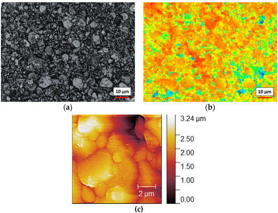
Figure 1.
Morphological characterization of the Al2O3 porous ceramic filter: (a) confocal laser scanning microscopy (CLSM) images with 150× magnification show the pressed Al2O3 grains of different sizes; (b) the height profile of the same section; (c) atomic force microscopy (AFM) scan images of a 10 µm × 10 µm area. The zero reference was set on lowest point of the picture. A pore is visible in the upper right corner.
For characterization of the hydrophilic behavior, a 10 µL drop of water was placed on the dry Al2O3 ceramic. For comparison, a second drop was placed on a hydrophobic polycarbonate surface. The evolution of the drop shape was recorded with a contact-angle measurement instrument (OCA 50 AF, DataPhysics Instruments GmbH, Filderstadt, Germany). Figure 2a,b show both drops at 0 s and at 0.8 s after placement of the drop on the ceramic. The quick absorption into the ceramic was clearly observed, and the 10 µL drop disappeared within approximately 1.6 s.

Figure 2.
Images of two 10 µL water drops on a hydrophobic polycarbonate (left) as a reference, and the hydrophilic Al2O3 ceramic for different times: (a) a snapshot of the first water ceramic contact (t = 0 s); (b) the drops after approximately 0.8 s. After approximately 1.6 s, the drop on the ceramic was fully absorbed.
From the porosity given in the datasheet and the volume of the ceramic filter, we calculated a solution volume of approximately 6 µL to fill the ceramic filter piece. In order to verify this volume, we measured the weight of the dehydrated filter (70.6 mg) and the fully saturated filter (84.3 mg) on a precision scale. This measurement had a significant systematic error, as water also wetted the surface of the ceramic, forming a puddle at the bottom. Thus, the water volume of approximately 13.7 µL obtained by weighing was an upper bound, and we believe the calculated 6 µL volume was a better estimate. This volume in the low µL range did not add significantly to the sample volume needed for the soil-solution analysis systems demonstrated so far [8,9,10,11].
2.2. Extraction Device Fabrication
The soil-solution extraction unit was fabricated with polydimethylsiloxane (PDMS) on a glass substrate. Figure 3a,c show a photograph and a schematic of the solution extraction device. The PDMS microfluidic chip was molded by using a Teflon mold as shown in Figure 3b, fabricated with a milling machine. It had a 12 mm microfluidic channel for extracted water transport with a quadratic cross section of 1 mm × 1 mm; i.e., the channel had a volume of 12 µL. The PDMS chamber was prepared by pouring the prepolymer of PDMS (SYLGARD® 184, Merck KGaA, Darmstadt, Germany) into the Teflon mold. It was hardened by baking in an oven at 90 °C for 1 h, and released after cooling down from the mold by peeling off from the master. The inlet of the fluidic was punched out with a biopsy punch (2 mm) and glued airtight with the 3 mm × 2.5 mm × 2 mm Al2O3 ceramic filter piece. Additionally, we drilled a port on the bottom side of the substrate and connected a silicone tube as the outlet.
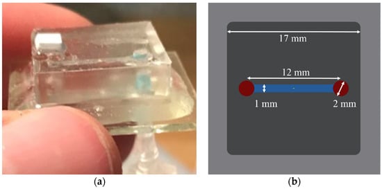
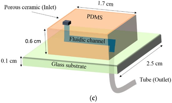
Figure 3.
(a) Photograph of the soil-solution extraction device. (b) mold schematic for fabrication of the PDMS microfluidic device. The 12 mm fluidic channel had a 1 mm × 1 mm channel cross section. (c) Schematic view of the full water-extraction device.
As the final step, the PDMS microfluidic chip with the ceramic filter at the inlet was attached to the glass substrate by using an epoxy adhesive. For a more complex microfluidic system, the bonding is preferentially done by an oxygen plasma treatment of the PDMS surface [9].
2.3. Hardware Setup
We realized the measurement setup depicted in Figure 4 for characterizing the water extraction unit. The purpose of these experiments was to determine the necessary soil moisture level for extraction to begin and to measure the extraction speed. The tube at the bottom of the glass substrate was connected to a low-power miniature peristaltic pump (RP-QX1.2N, Ring Pump, Aquatech Co., Ltd., Osaka, Japan) to create suction. We used a Raspberry Pi 4 system and a motor driver (TB6612, Adafruit Industries) to control the peristaltic pump and read the soil-moisture sensor (SMT100, Truebner GmbH, Bad Schwartau, Germany). The SMT100 measured the volumetric water content and the temperature in the soil near the measuring surface based on time-domain reflectometry (TDR) and frequency domain reflectometry (FDR). The low-power peristaltic pump (0.36 W at 3 V) generated a maximum pump pressure of 0.5 bar (50 kPa). The extraction of soil solution was achieved by the underpressure inside the microfluidic channel while pumping.
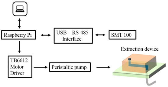
Figure 4.
Hardware setup for testing the soil-solution extraction system. A miniature peristaltic pump and a reference soil-moisture sensor SMT100 were controlled by a Raspberry Pi 4 system.
2.4. Procedures for Soil-Sample Experiments
To estimate the behavior of our system, we investigated the extraction of soil solution with different types of soil. The tested soil types were silt, garden soil, and sand, chosen for their different water-holding capacities (Figure 5). The samples were collected in the field and separated (except garden soil) by wet sieving into their components, without further analysis of the soil components. Here, we examined the correlation between the soil moisture and the amount of extracted soil solution for a given pump duration.
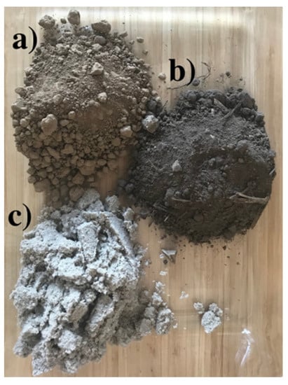
Figure 5.
Tested soil types: (a) silt; (b) garden soil; (c) sand.
Figure 6 shows a photograph of the experimental setup with garden soil. The garden soil sample was piled up in a plastic box. The extraction device and the soil-moisture sensor SMT100 were installed adjacent to each other. Good soil contact was essential for the reference sensor and the porous ceramic of the extraction device, since larger air inclusions can lead to a lower water extraction. Thus, care should be taken in placing the sensor to avoid a larger air gap. As shown in Section 2.1, it was not problematic if the sensor was dry at the beginning, as the wicking also began for a dry ceramic filter.
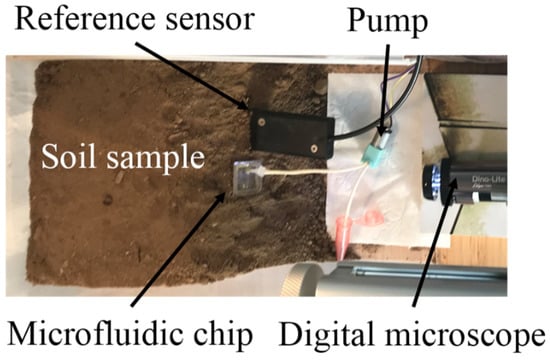
Figure 6.
Characterization setup for soil-solution extraction unit. This garden soil sample was prepared in a plastic box (30 cm × 16 cm × 12 cm). The upper side of the device was pushed approximately 5 mm into the soil.
All three samples were prepared with the same volume of approximately 2500 cm3. For reproducibility of the initial filter condition in repeated measurements, the aluminum oxide membrane was moistened at the beginning of the experiments. As discussed in Section 2.1, we could also use a dry filter, as this was filled quickly by wicking. We chose the wetting method, as the integrated filter could not be dried on a hot plate, and drying without temperature would require much more time than wetting. Furthermore, we measured the initial moisture content of the soil sample. Next, the effect of changing water content was analyzed by subsequently adding 100 mL of water on top of the soil sample with a spray bottle. After 15 min, we measured the moisture condition and activated the pump for 30 min. Hereafter, the pump was separated from the extraction device in order to transfer the extracted water to a beaker. To keep the contact condition between the soil and the microfluidic chip, we left the device inside the soil and evaluated the solution content inside the pump tube only.
The procedure of adding 100 mL of water with the spray bottle, pumping, and measuring the extracted water amount was iterated until the water-holding capacity of the soil was exceeded and the water ran out at the lowest point of the sample.
For characterization and better understanding of the system, the extraction of water into the microfluidic was filmed with a digital microscope (Dino-Lite AM7115MZTL, Bürklin GmbH & Co. KG, Oberhaching, Germany). We stress that the entire procedure of 30 min of pumping, transfer of the extracted water to a beaker, and filming with the digital microscope was only performed for extraction-unit characterization. For a field-deployed system, it would simply be required to add a pump to the microfluidic chip for suction and run the pump until the desired volume is extracted.
3. Experimental Results
3.1. Water Extraction into the Microfluidic Chip
Water was successfully extracted from all three soil types into the microfluidic chip. This demonstrated that the soil-extraction unit was functional for a sufficient moisture level. The following experiments show the beginning of the solution extraction at a 15 Vol.-% moisture level after adding 300 mL of water. Figure 7a–d show a time sequence of the extraction process into the microfluidic channel for garden soil. The 12 µL volume of the microfluidic channel was filled after approximately 8 min.
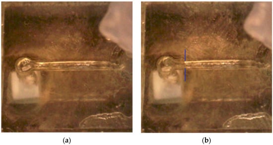
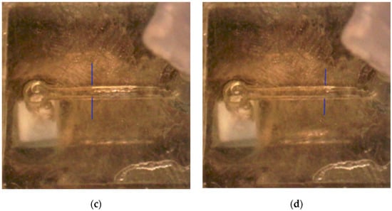
Figure 7.
(a–d) Images of the garden soil solution extraction process after: (a) 0 min; (b) 1.5 min; (c) 2.5 min; and (d) 4.5 min. The position of the water column was barely visible, and is marked with the blue lines. The microfluidic channel was filled after approximately 8 min.
Figure 8 presents a plot of the liquid propagation inside the microfluidic device during the extraction measurement. The plot shows the filling of the 12 mm channel within 512 s. The analyzed distances were directly translated into the amount of extracted soil solution by considering the channel cross section. We observed an approximately linear filling behavior of the device with time. From the data, an extraction rate of approximately 1.4 µL/min was deduced. From these experiments, we expected an extraction volume of approximately 40 µL after the 30 min extraction interval for 300 mL of added water.
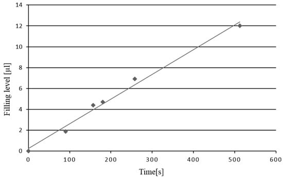
Figure 8.
Evaluation of the microfluidic filling level. The data show the propagation of the soil solution over the 12 mm channel. The volume was calculated by analyzing the microscope images.
3.2. Experiments with Different Soil Types
For comparison of water extraction from different soil types, we always extracted water for 30 min and measured the amount of extracted solution in the tube as described in Section 4.2. Thus, this water volume was in addition to the channel volume. The temperature of the samples was consistently between 21 °C and 22 °C. Table 1 gives the experimental results for the extracted soil water from the three different types of soil.

Table 1.
Experimental series of water extraction for different soil moisture levels in three types of soil. The moisture level was increased by adding water in steps. The volume of extracted solution for a 30 min pump period was measured. As the experiment was stopped at different amounts of added water, we do not have values for all fields.
We observed that the amount of added water resulted in different moisture conditions of the soil samples. The water-holding capacities of the soil samples were different, as expected. Therefore, the extracted solution was stagnant when initially adding water. The reason for this effect can be described by the capillary matric potential of soil [24]. The movement of soil water inside the soil matrix typically takes place from wet to drier regions. This is referred to as different matric potentials of the soil, which describes the attractive force between the particles and water inside the soil. Dryer soil regions have higher matric potential. For sampling of soil water, the forces generated by the applied vacuum inside the ceramic must be higher than the capillary matric potential of the soil. Since we kept the suction constant, the moisture had to be increased by adding water to the sample and lowering the matric potential. The different values within the samples resulted from the texture dependency of the capillary forces inside the soil matrix. Silt showed the highest water-holding capacity. Due to the higher soil moisture tension, the moisture level was increased to approximately 13 Vol.-% after adding 500 mL of water. At this point, the extraction of water into the microfluidic device began. In contrast to silt, the extraction of the soil solution began after adding 200 mL of water to garden soil and sand at 11 Vol.-% and 8 Vol.-%, respectively.
3.3. Analysis of Measurement Variability
To investigate the measurement variability in this experimental procedure, we conducted the experiment with garden soil two more times. The garden soil was changed between the measurements. Table 2 shows the data comparison of the three measurement iterations. We observed that the initial water extraction began at different moisture conditions. As already shown in Table 1, the extraction began at 11 Vol.-% for the first run with garden soil. For the second and the third iterations, we began extracting soil water at 14 Vol.-% and 6 Vol.-%, respectively.

Table 2.
Experimental series of repeated water extraction from garden soil for different soil moisture levels. The moisture level was increased by adding water in steps. The volume of extracted solution for a 30 min pump period was measured.
A possible reason for this divergence was the uneven distribution of water bound inside the soil, as well as air bubbles. We expect that the small microfluidic extraction unit with ceramic inlet was more sensitive to inhomogeneous water distribution, as the sampled soil volume was much smaller than for the rather large reference sensor SMT100. Additionally, the structure of the soil also had a great impact on capillary effects between the soil solution and the porous membrane. As we changed the soil between iterations and repositioned the microfluidic extraction unit, this contact was not constant between iterations.
Figure 9a shows the correlation between the added water on top of the soil sample and the measured soil moisture with the reference sensor. We plotted all three measurements with garden soil to investigate the error propagation within a measurement. The plot showed a moderate deviation. We suggest this was mainly due to the inhomogeneous water distribution inside the soil sample.
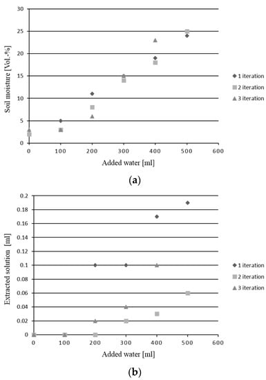
Figure 9.
Evaluation of measurement variability: (a) soil moisture with added water; and (b) extracted soil solution with added water for three measurement iterations.
Figure 9b shows the amount of extracted soil solution after adding water. It was observed that the water extraction start points were different for the three soils, varying between 200 and 300 mL of added water. The small size of the membrane coupled with the water distribution variability inside the soil structure led to the variability in the extracted amount of water. At 400 mL of added water, the extracted water volume had the largest variability, with values between 0.03 mL and 0.17 mL.
4. Discussion of Experimental Results
4.1. Necessary Soil-Moisture Level
In all experiments, soil water was extracted successfully from the soil into the microfluidic chip. The necessary level of soil moisture was determined to be approximately 13 Vol.-% for silt, 11 Vol.-% for garden soil, and 8 Vol.-% for sand. Therefore, the proposed soil-solution extraction unit is particularly suited to extracting water in the nonequilibrium state after watering the field or a rainfall. Since nutrients are particularly susceptible to leaching through the soil profile [25], this transfer of chemicals during rainfall is a promising circumstance for using in situ soil water samplers without applying high vacuum potentials for the suction lysimetric approach. Thus, the system becomes energy-efficient, and may be miniaturized. In-depth tests are still required to determine the temporal correlation between soil nutrients dissolved in the soil water and bound to the solid soil phase. Here, the proposed extraction unit could be used in combination with one of the microfluidic analysis systems developed by other groups to gain valuable insights into the soil dynamics by continuous in situ measurements.
4.2. Volume of Extracted Water
In the characterization experiments, extraction rates in the µL/min range were demonstrated. In microfluidic lab-on-chip systems, typically solution volumes in the µL range are used, and these volumes may be extracted within minutes. In addition, the amount of solution stored in the ceramic membrane must be exchanged for correct measurement of a given sampling time. For the characterization experiments, we moistened the ceramic filter in order to create reproducible conditions. As the ceramic filter stored approximately 6 µL, this volume had to be extracted in addition to the volume needed in the microfluidic chip. An even smaller ceramic filter may be used to reduce this volume further. In the experiments shown in Figure 2, it is visible that water extraction also began for a dry ceramic filter. Thus, it was not a fundamental problem if the filter was dry or air bubbles were in the soil. This only affected the amount of extracted water per time unit, and air inclusions had to be eliminated in the subsequent microfluidic chip.
4.3. Pump Choice for Field Deployment
For field deployment, the proposed extraction unit needs to be combined with a microfluidic analysis system and a pump. The compact and low-power (<360 mW) peristaltic pump used in the characterization experiments is one good choice, as long as the soil solution is extracted from well-watered soil. The peristaltic pump may also be integrated directly on the chip, or replaced with an even smaller actuator based on piezoelectric devices. For even further miniaturization, capillary pumping is of high interest [26]. For even lower system power levels, approaches for moving liquids inside a microfluidic system without using a pump may be considered [27,28]. Here, the possible operation time if using a porous PDMS sponge or a reinforced balloon must be compared to a battery-operated pump system. As long as the analysis system and communication system also require a battery, a miniature electric pump seems to be the best choice.
For extraction of soil solution from soil of a high matric potential, much higher suction forces are necessary, and a different approach with a stronger pump and wiring to a larger power supply is needed. Weihermüller [29] conducted silt numerical simulations using the physically based convection–dispersion equation (CDE). He showed that the amount of the extracted water increased with higher suction rates (approaching an asymptotic value of the system). Additionally, different soil samples showed, as expected, different extraction rates, with clay loam and sandy soil as the highest and the lowest, respectively. These simulations matched our results, since silt is a component of loam. Van der Ploeg and Beese made similar observations. They observed a nonlinear relation between the suction and the extracted water [30].
In our proof-of-principle experiments, we did not observe any coagulation effects. For long-term operation of the filter, fine soil particles may coagulate in the system. For cleaning of the system, approaches such as backflushing of the particles by reversing the flow direction of the peristaltic pump may be considered, and thus a pump and microfluidic system suitable for bidirectional operation is preferred for the next step of a long-term field test. In this context, it would also be interesting to investigate the influence of the best pore size in more detail. A careful balance between the pore size and the power consumption must be found for field application. The soil particle sizes range from 0.2 µm to 2 mm [31] for fine clay to very coarse sand, respectively. Higher pore sizes lead to detrimental filter quality, since more particles would enter the ceramic unit. Lower pore size would require higher suction potential at the ceramic/water interface; i.e., the setup would need a pump with higher power.
Finally, the pump cost was the dominant cost factor in our current system. The overall system cost of the pump, electronics, and microfluidics for our proof-of-principle extraction system was approximately EUR 100. Here, the pump accounted for around 70% of the costs. Thus, for a cost-efficient system, the price of the pump is an important factor, and the necessary performance parameters must be carefully evaluated in long-term experiments to reduce cost.
4.4. Susceptibility to Inhomogeneities
The repeated experiments using garden soil showed that due to the small collection volume, the microfluidic system was inherently susceptible to inhomogeneities in the soil. Additionally, it must be considered that the soil properties and moisture level vary from one area to another on a single agricultural field. Shallow regions in the field may have a much higher moisture level than elevated regions. Weihermüller depicted in his PhD thesis [29] that the reliability of suction cups and commercially available lysimeters is increased by the deployment of numerous samplers to obtain a good average. Thus, the problem of dealing with inhomogeneities is known from larger systems, and we propose a distributed network of miniaturized sensors for spatially resolved monitoring of soil nutrients.
In addition, it has been recognized previously in the literature that the soil-solution extraction method may bias the result of the nutrient concentrations derived for the soil [5,6]. These effects were also expected for our approach, and need to be analyzed in field studies. Relative concentrations of different nutrients provide additional information. Contrary to the traditional approach of calculating the nutrient concentration for a fixed soil volume or mass, in soil-solution analysis approaches, the concentration is related to the solution volume [9,10]. Regarding the different amounts of extracted solution in the repeated experiments shown in Figure 9, it was concluded that a monitoring of the extracted water amount should be implemented to determine the necessary pump duration.
5. Conclusions
In conclusion, we demonstrated the fabrication and function of a microfluidic soil-solution extraction chip. Soil water was extracted successfully from three types of soil—silt, garden soil, and sand—with a rate in the µL/min range. This device is promising as an extraction unit for continuous sensing systems, as well as for discrete time-point sensing in agriculture. The proposed extraction unit may be combined with any of the microfluidic analysis systems proposed in the literature [8,9,10,11]. Low-power and long-range data transmission standards such as Long Range (LoRa) are particularly suitable, and the Internet of Underground Things (IoUT) is being established [32,33]. Combining the proposed low-power soil-solution extraction unit, a low-power microfluidic analysis system and a low-power communication standard brings a wireless, low-maintenance stand-alone system for chemical nutrient analysis into reach. As the next steps, this integration should be accomplished, and extensive field testing be performed.
The deployment of microfluidic systems in the agricultural field is not only limited to investigations on soil solution. Studies on environmental organisms, root bacteria, and simulating microbial ecology in soil systems were carried out in the past two decades [34,35,36]. Stanley et al. [37] provide a critical review on Soil-on-a-Chip or Plant-in-Chip technologies for soil organisms studies and their interactions with the environment. A merging of the two research areas promises additional insights.
Author Contributions
Conceptualization, S.B., I.T. and M.G.; data curation, S.B. and I.T.; formal analysis, I.T. and M.G.; funding acquisition, M.G.; investigation, I.T. and M.G.; methodology, S.B.; project administration, I.T. and M.G.; resources, I.T. and M.G.; supervision, I.T. and M.G.; validation, I.T. and M.G.; visualization, S.B.; writing—original draft, I.T. and M.G.; writing—review and editing, I.T. and M.G. All authors have read and agreed to the published version of the manuscript.
Funding
This work was supported in part by ZIM (Project AuToilette, ZF4558802RH8). The authors also acknowledge financial support by DFG within the funding programme Open Access Publizieren.
Institutional Review Board Statement
Not applicable.
Informed Consent Statement
Not applicable.
Acknowledgments
The authors acknowledge the Institute of Plant Nutrition and Soil Science at Kiel University for providing soil samples, and Kerafol Keramische Folien GmbH & Co. KG for the test samples of Keralpor 99.
Conflicts of Interest
The authors declare no conflict of interest.
References
- Forde, B.; Lorenzo, H. The nutritional control of root development. In Interactions in the Root Environment: An Integrated Approach; Springer: Dordrecht, The Netherlands, 2002; pp. 51–68. [Google Scholar] [CrossRef][Green Version]
- Robert, P.C. Precision agriculture: A challenge for crop nutrition management. Plant Soil 2002, 247, 143–149. [Google Scholar] [CrossRef]
- Hallberg, G.R. Pesticides pollution of groundwater in the humid United States. Agric. Ecosyst. Environ. 1989, 26, 299–367. [Google Scholar] [CrossRef]
- Singh, G.; Kaur, G.; Williard, K.; Schoonover, J.; Kang, J. Monitoring of Water and Solute Transport in the Vadose Zone: A Review. Vadose Zone J. 2017, 17, 160058. [Google Scholar] [CrossRef]
- Weihermüller, L.; Siemens, J.; Deurer, M.; Knoblauch, S.; Rupp, H.; Göttlein, A.; Pütz, T. In Situ Soil Water Extraction: A Review. J. Environ. Qual. 2007, 36, 1735–1748. [Google Scholar] [CrossRef]
- Curley, E.M.; O’flynn, M.; McDonnell, K. Porous Ceramic Cups: Preparation and Installation of Samplers for Measuring Nitrate Leaching. Int. J. Soil Sci. 2009, 5, 19–25. [Google Scholar] [CrossRef][Green Version]
- Chen, Y.; Tian, Y.; Wang, X.; Wei, L.; Dong, L. Miniaturized, Field-Deployable, Continuous Soil Water Potential Sensor. IEEE Sens. J. 2020, 20, 14109–14117. [Google Scholar] [CrossRef]
- Kim, D.; Goldberg, I.B.; Judy, J.W. Microfabricated electrochemical nitrate sensor using double-potential-step chronocoulometry. Sens. Actuators B Chem. 2009, 135, 618–624. [Google Scholar] [CrossRef]
- Xu, Z.; Wang, X.; Weber, R.J.; Kumar, R.; Dong, L. Nutrient Sensing Using Chip Scale Electrophoresis and In Situ Soil Solution Extraction. IEEE Sens. J. 2017, 17, 4330–4339. [Google Scholar] [CrossRef]
- Kokkinis, G.; Kriechhammer, G.; Scheidl, D.; Wilfling, B.; Smolka, M. Towards the Commercialization of a Lab-on-a-Chip Device for Soil Nutrient Measurement. In Information and Communication Technologies in Modern Agricultural Development, Proceedings of the 8th International Conference (HAICTA 2017), Chania, Greece, 21–24 September 2017; Springer: Cham, Switzerland, 2019; pp. 118–130. [Google Scholar]
- Dudala, S.; Dubey, S.K.; Goel, S. Microfluidic Soil Nutrient Detection System: Integrating Nitrite, pH, and Electrical Conductivity Detection. IEEE Sens. J. 2020, 20, 4504–4511. [Google Scholar] [CrossRef]
- Jahns, S.; Bräu, M.; Meyer, B.-O.; Karrock, T.; Gutekunst, S.B.; Blohm, L.; Selhuber-Unkel, C.; Buhmann, R.; Nazirizadeh, Y.; Gerken, M. Handheld imaging photonic crystal biosensor for multiplexed, label-free protein detection. Biomed. Opt. Express 2015, 6, 3724–3736. [Google Scholar] [CrossRef]
- Jahns, S.; Gutekunst, S.B.; Selhuber-Unkel, C.; Nazirizadeh, Y.; Gerken, M. Human blood microfluidic test chip for imaging, label-free biosensor. Microsyst. Technol. 2016, 22, 1513–1518. [Google Scholar] [CrossRef]
- Titov, I.; Kopke, M.; Schneidewind, N.C.; Buhl, J.; Murat, Y.; Gerken, M. OLED-OPD Matrix for Sensing on a Single Flexible Substrate. IEEE Sens. J. 2020, 20, 7540–7547. [Google Scholar] [CrossRef]
- Joekar-Niasar, V.; Schreyer, L.; Sedighi, M.; Icardi, M.; Huyghe, J. Coupled Processes in Charged Porous Media: From Theory to Applications. Transp. Porous Media 2019, 130, 183–214. [Google Scholar] [CrossRef]
- Li, Z.; Giese, R.F.; Oss, C.J.; Kerch, H.M.; Burdette, H.E. Wicking Technique for Determination of Pore Size in Ceramic Materials. J. Am. Ceram. Soc. 1994, 77, 2220–2222. [Google Scholar] [CrossRef]
- Kissa, E. Wetting and Wicking. Text. Res. J. 1996, 66, 660–668. [Google Scholar] [CrossRef]
- Suits, L.D.; Sheahan, T.C.; Cui, Y.-J.; Tang, A.M.; Mantho, A.T.; De Laure, E. Monitoring Field Soil Suction Using a Miniature Tensiometer. Geotech. Test. J. 2008, 31, 95–100. [Google Scholar] [CrossRef]
- Spangenberg, A.; Cecchini, G.; Lamersdorf, N. Analysing the performance of a micro soil solution sampling device in a laboratory examination and a field experiment. Plant Soil 1997, 196, 59–70. [Google Scholar] [CrossRef]
- Göttlein, A.; Hell, U.; Blasek, R. A system for microscale tensiometry and lysimetry. Geoderma 1996, 69, 147–156. [Google Scholar] [CrossRef]
- Hädrich, F.; Stahr, K.; Zöttl, H.W. Die Eignung von Al2O3-Keramik und Ni-Sinterkerzen zur Gewinnung von Bodenlösungen für die Spurenelementanalyse. Mitteilungen der Deutschen Bodenkundlichen Gesellschaft; DBG: Bremen, Germany, 1977; No. 25-1; pp. 151–162. [Google Scholar]
- Berger, W.; Kalbe, U. “Saugsonden zur Untersuchung der Bodenwasserbeschaffenheit: Ein Überblick der Einsatzmöglichkeiten”; TerraTech 11-12; Vereinigte Fachverlage GmbH: Mainz, Germany, 2004; pp. 8–12. [Google Scholar]
- Silkworth, D.R.; Grigal, D.F. Field Comparison of Soil Solution Samplers. Soil Sci. Soc. Am. J. 1981, 45, 440–442. [Google Scholar] [CrossRef]
- Warrick, A.W. Soil Water Dynamics; Oxford University Press: Oxford, UK, 2003. [Google Scholar] [CrossRef]
- Kumar, A.; Kanwar, R.; Singh, P.; Ahuja, L. Evaluation of the root zone water quality model for predicting water and NO3–N movement in an Iowa soil. Soil Tillage Res. 1999, 50, 223–236. [Google Scholar] [CrossRef]
- Guo, W.; Hansson, J.; Van Der Wijngaart, W. Capillary pumping independent of the liquid surface energy and viscosity. Microsyst. Nanoeng. 2018, 4, 2. [Google Scholar] [CrossRef]
- Thurgood, P.; Baratchi, S.; Szydzik, C.; Mitchell, A.; Khoshmanesh, K. Porous PDMS structures for the storage and release of aqueous solutions into fluidic environments. Lab Chip 2017, 17, 2517–2527. [Google Scholar] [CrossRef]
- Thurgood, P.; Suarez, S.A.; Chen, S.; Gilliam, C.; Pirogova, E.; Jex, A.R.; Baratchi, S.; Khoshmanesh, K. Self-sufficient, low-cost microfluidic pumps utilising reinforced balloons. Lab Chip 2019, 19, 2885–2896. [Google Scholar] [CrossRef]
- Weihermüller, L. Comparison of Different Soil Water Extraction Systems for the Prognoses of Solute Transport at the Field Scale Using Numerical Simulations, Field and Lysimeter Experiments. Ph.D. Dissertation, Rheinische Friedrich-Wilhelms-Universität, Bonn, Germany, 2005. [Google Scholar]
- Van Der Ploeg, R.R.; Beese, F. Model Calculations for the Extraction of Soil Water by Ceramic Cups and Plates. Soil Sci. Soc. Am. J. 1977, 41, 466–470. [Google Scholar] [CrossRef]
- Webster, R. Soil Sampling and Methods of Analysis—Edited by M.R. Carter & E.G. Gregorich. Eur. J. Soil Sci. 2008, 59, 1010–1011. [Google Scholar] [CrossRef]
- Grunwald, A.; Schaarschmidt, M.; Westerkamp, C. LoRaWAN in a rural context: Use cases and opportunities for agricultural businesses. In Proceedings of the Mobile Communication—Technologies and Applications; 24. ITG-Symposium, Osnabrueck, Germany, 15–16 May 2019; pp. 134–139. [Google Scholar]
- Salam, A.; Vuran, M.C.; Irmak, S. Di-Sense: In situ real-time permittivity estimation and soil moisture sensing using wireless underground communications. Comput. Netw. 2019, 151, 31–41. [Google Scholar] [CrossRef]
- Parashar, A.; Pandey, S. Plant-in-chip: Microfluidic system for studying root growth and pathogenic interactions in Arabidopsis. Appl. Phys. Lett. 2011, 98, 263703. [Google Scholar] [CrossRef]
- Massalha, H.; Korenblum, E.; Malitsky, S.; Shapiro, O.H.; Aharoni, A. Live imaging of root–bacteria interactions in a microfluidics setup. Proc. Natl. Acad. Sci. USA 2017, 114, 4549–4554. [Google Scholar] [CrossRef]
- Aleklett, K.; Kiers, E.T.; Ohlsson, P.; Shimizu, T.S.; Caldas, V.E.; Hammer, E.C. Build your own soil: Exploring microfluidics to create microbial habitat structures. ISME J. 2018, 12, 312–319. [Google Scholar] [CrossRef]
- Stanley, C.E.; Grossmann, G.; Solvas, X.C.I.; Demello, A.J. Soil-on-a-Chip: Microfluidic platforms for environmental organismal studies. Lab Chip 2016, 16, 228–241. [Google Scholar] [CrossRef]
Publisher’s Note: MDPI stays neutral with regard to jurisdictional claims in published maps and institutional affiliations. |
© 2021 by the authors. Licensee MDPI, Basel, Switzerland. This article is an open access article distributed under the terms and conditions of the Creative Commons Attribution (CC BY) license (https://creativecommons.org/licenses/by/4.0/).