1. Introduction
The growing global demand for food will be a major challenge for agriculture, together with the necessity to support the emergence of technologies able to meet environmental and ethical standards, promoting also efficiency and healthy work environments [
1]. The UN Food and Agriculture Organization (FAO) and other research studies estimate that 20–40% of global crops are lost due to plant pests and diseases [
2]. Farmers use chemicals to mitigate damages caused by pests, which interferes with the production of crops, affecting quality. Pesticide residues resulting from the use of plant protection products on food or feed crops may be a risk to public health.
Precision spraying in agriculture represents an innovative methodology that can help farmers to spray only where needed, using the right amount of chemicals [
3]. This can improve the efficiency of treatments, reducing costs and chemical waste. Moreover, precision spraying can help to fulfil legal requirements, in terms of worker health [
4], environmental sustainability, and food safety and quality. However, most suppliers do not offer robots and integrated systems that are able to operate in narrow and steep spaces or in the presence of obstacles, as in the case of greenhouses or terraced cultivations.
The subject of this work is a system capable of distributing inputs (e.g., crop/plant protection products, bio-agro drugs, pesticides, powders) in an efficient, sustainable, and safe way, in environments where standard agricultural machineries (automated or autonomous) cannot operate: greenhouses, mountainous areas, and heroic cultivations.
The adoption of autonomous robots can help in optimizing the agricultural operations, increasing productivity and safety. Moreover, the costs of technological devices (e.g., electrical motors, batteries, computers, sensors) is reduced from year to year, allowing these robotic systems to become easily wide-spread of among farmers. A quite complete review of the basic concepts of agricultural robotics is reported in [
5,
6]. Here common robotic architectures, components, and applications are discussed in depth. Many research activities deal with the adoption of robotics in agriculture [
7]. For example, a robot for crop and plant management is presented in [
8], while Vasconez et al. [
9] provide a general description of the potentiality of human–robot interaction (HRI) in many agriculture activities, such us harvesting, handling, and transporting.
Agricultural robots are typically autonomous or semi-autonomous systems that can be operated in several stages of the process. In particular, robots that must operate inside greenhouses and vineyards have to deal with very tight passages while avoiding damages to the plants. Moreover, they should have very good performance regarding path following, during turn maneuvers at headlands. Several localization and navigation solutions have been implemented. A laser-guided path follower technique was tested in [
10]. The system is stated to be very reliable, but requires several lasers to be mounted in the proximity of corridors. In [
11], different approaches were used regarding sensors and algorithms. Some trials were performed using map-based techniques and using motor encoders for localization.
A combination of the Hector Simultaneous Localization and Mapping (SLAM) and an artificial potential field (APF) controller is used in [
12] to estimate the robot’s position and to perform autonomous navigation inside the greenhouse.
In Reis et al. [
13], a multi-antenna receiver Bluetooth system and the obtained transfer functions (from received signal strength indication (RSSI) to distance estimation) are used as redundant artificial landmarks for localization purposes.
In Tourrette et al/. [
14], a solution based on the cooperation of at least two mobile robots—a leader and a follower, moving from either side of a vine row—is investigated thanks to ultra-wideband (UWB) technology. In particular, the formation control of the follower with respect to a leader is proposed, allowing relative localization without visual contact and avoiding the limitations of GPS when moving near to high vegetation.
Many EU-funded projects concerning vineyards have recently concluded. One of these is Vinerobot [
15], whose aim was the development of a system able to monitor vineyard physiological parameters and grape composition. Another European project is VinBot [
16]. VinBot is an all-terrain autonomous mobile robot with a set of sensors capable of capturing and analyzing vineyard images and 3D data by means of cloud computing applications, in order to determine the yield of vineyards and to share this information with the winegrowers. The robot will help winegrowers in defoliation, fruit removal, and sequential harvesting by grapes’ ripeness.
As regards spraying robots, image processing algorithms for the detection and localization of the grape cluster and of the foliage for selective spraying are presented in Berenstein et al. [
17]. In this case, the system was tested on a manually driven cart.
A specially designed algorithm to measure complex-shaped targets using a 270° radial laser scanning sensor is presented in Yan et al. [
18] for the future development of automatic spray systems in greenhouse applications.
Adamides et al. [
19] compare different user interfaces (i.e., human–machine interface, HMI) for a teleoperated robot for targeted spraying in vineyards. It compares different approaches with dedicated input devices such as a joypad or a standard keyboard, different output devices such as a monitor or a head-mounted display, and different vision mechanisms.
Within the project CROPS [
20], a robotic system with a six degrees of freedom manipulator, an optical sensor system, and a precision spraying actuator was developed. The precision spraying end-effector is positioned by the robotic manipulator to selectively and accurately apply pesticides. The project Flourish [
21] is also concerned with autonomous selective spraying operations in open fields using a cooperative unmanned aerial and ground vehicles approach.
However, in most cases, the developed prototypes presented above are just proof-of-concept, and are not sufficiently robust for the real agricultural environment. Our system attempts to bridge the gap between all the prototype solutions described above and those big machines that already work in large crops and farms (i.e., John Deere, New Holland, etc.), which cannot be considered as solutions applicable in greenhouses or heroic cultivations and vineyards. Moreover, in terms of versatility, compared to some of the previous solutions, our system does not require the installation of rails between the rows and can be used in different kinds of crops and terrains.
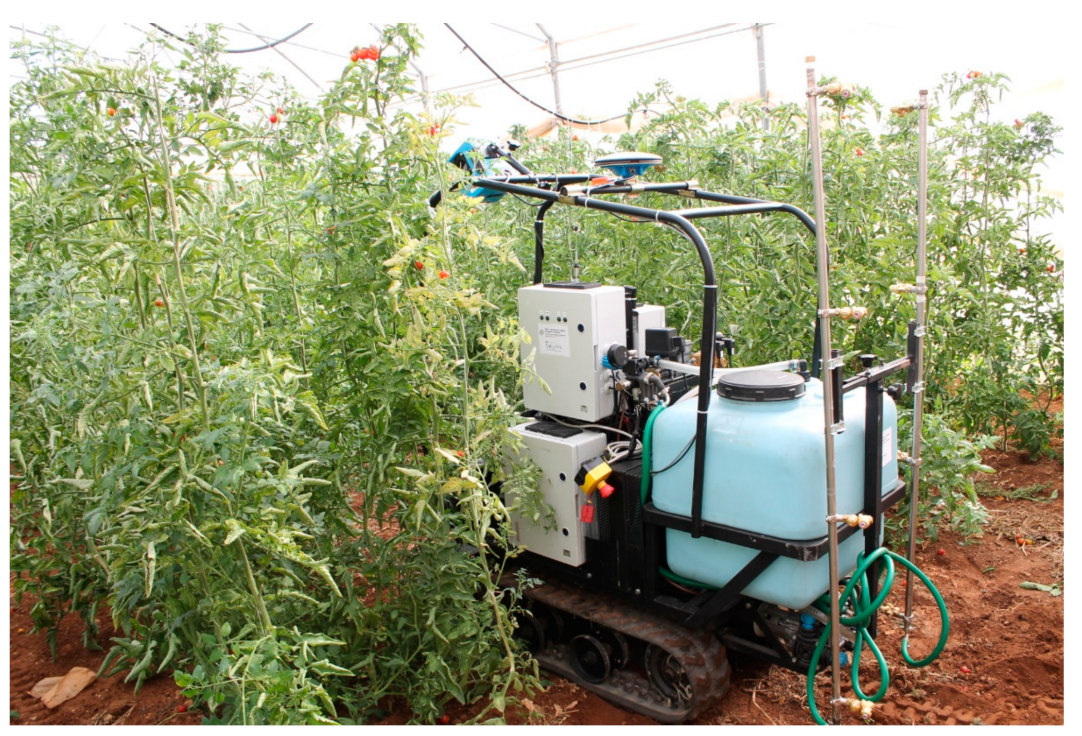
The heart of the system we developed is represented by an agile autonomous robotic vehicle able to move in environments where standard agricultural machineries (automated or autonomous) cannot operate: greenhouses, mountainous areas, and heroic cultivations. The vehicle, shown in
Figure 1, is equipped with a “smart spraying system” capable of optimizing the spraying operations.
Furthermore, the developed human–machine interface also allows unskilled operators to plan spraying treatments, to monitor the mission from a safe distance, and to generate a report of the treatments at the end of the operations.
2. Materials and Methods
The developed architecture consists of four main subsystems, described in the following sub-sections.
2.1. Mobile Tracked Robot
The robot is based on the “U-Go” robot—one of the multifunctional vehicles developed in our DIEEI Robotic Laboratories at University of Catania, mainly to solve problems like transportation, navigation, and inspection in very harsh outdoor environments [
22,
23]. It is a rubber-tracked vehicle equipped with electric traction: two motor drivers, connected to two 1 kW 24 V DC brushed motors, acting on the tracks, can be commanded via CAN bus. The compact external dimensions (880 mm (L) × 1020 mm (W)) also make the machine highly maneuverable between narrow passages. It allows the transport of a payload of about 200 kg, at a maximum speed of 3 km/h. It is able to exceed a maximum slope of 30 degrees, and has an autonomy of 6–8 h.
The vehicle is equipped with several sensors for autonomous navigation in rough outdoor environments: a stereo camera, a RTK-DGPS GNSS receiver, an attitude and heading reference system (AHRS), a laser scanner rangefinder, ultrasonic sensors, and motor encoders. An embedded acquisition and control system, based on the sbRIO-9626 board by National Instruments, acts as low-level interface with the sensors and actuators. A custom protocol based on User Datagram Protocol (UDP) is adopted to communicate and interact with the sbRIO over a wired Ethernet or WiFi connection. It is possible to retrieve all the sensors’ data (GPS, attitude, etc.) and to send commands to the board. For example, linear and angular desired speeds can be passed via UDP to the sbRIO; this uses the robot kinematics equations to compute the reference signals to be assigned to the vehicle’s two motor drivers. This kind of architecture ensures hardware and software modularity: an on-board companion computer or a remote base station can be used to interface and communicate with the mobile tracked vehicle in order to implement high-level control algorithms, while demanding the low-level tasks of the sbRIO.
2.2. Localization and Navigation System
This subsystem fuses the information coming from the on-board sensors to accurately determine the position and attitude of the vehicle, used to autonomously execute the assigned trajectories and avoid obstacles.
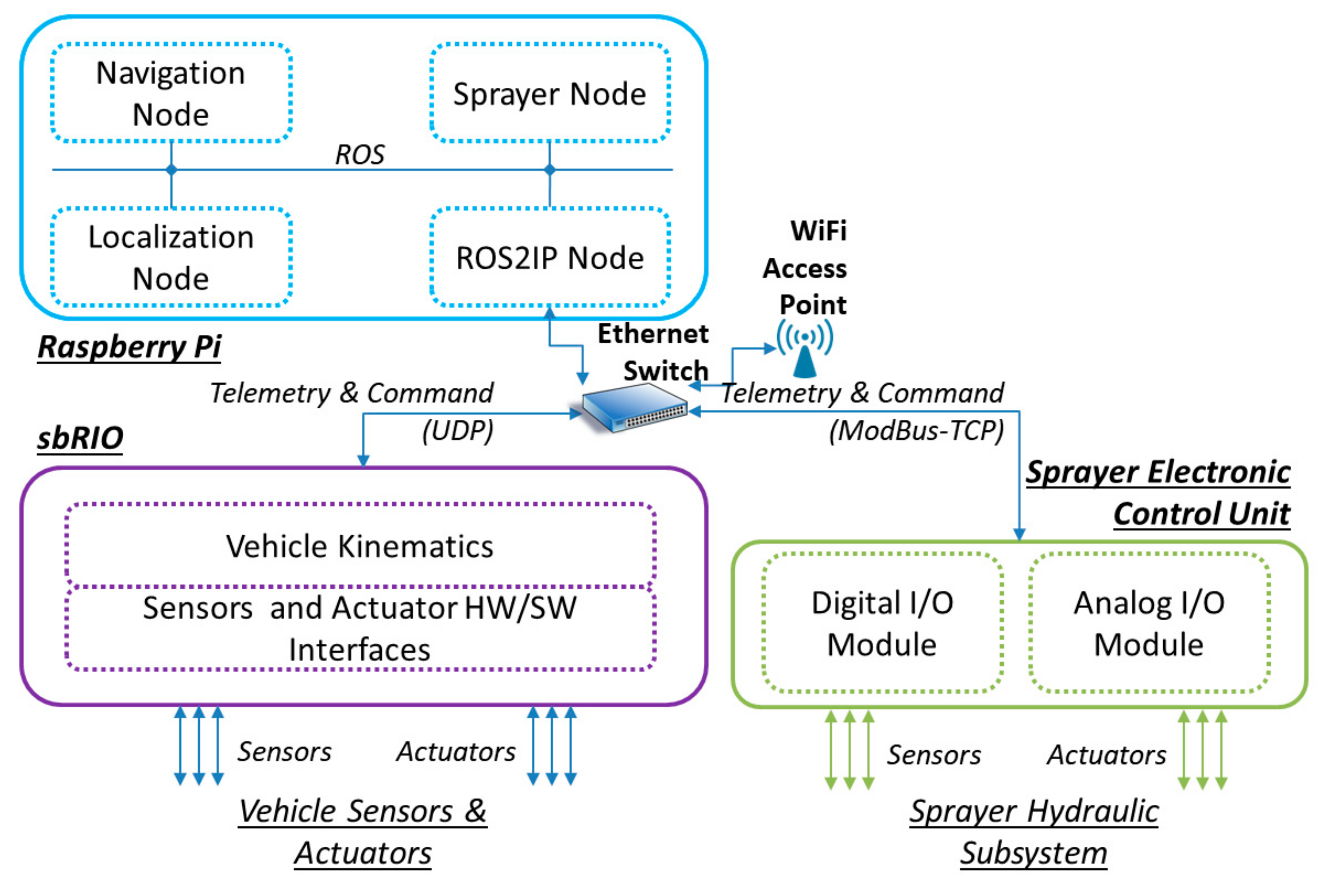
A Raspberry Pi 3 (RPi) was used as an on-board companion computer, running the high-level algorithms of the localization and navigation system. The two software subsystems (Localization and Navigation modules) run in the RPi as two ROS (robot operating system) nodes (
Figure 2) [
24]. RPi communicates with the sbRIO by means of the aforementioned UDP protocol: the ROS2IP node of
Figure 2 translates custom UDP messages to ROS messages and vice versa.
In particular, the Localization node implements an extended Kalman filter to fuse the data coming from the sensors, in order to evaluate robot position and heading. Moreover, the sensor suite and the Localization node allow several high-level tasks to be performed:
However, in the case of study reported in this work, the Localization node uses only a subset of the sensors suite to evaluate robot position and heading:
Absolute positions are measured integrating the measures of the encoders with the information coming from a Leica Viva GS10, which is a high-precision GNSS receiver; it uses Leica Geosystems SmartNet—a GNSS Network Real-time Kinematic (RTK) correction service delivered over cellular network—to achieve centimeter-accurate positioning without the need for an RTK base station.
Attitude is derived from X-Sens MTi-30, a MEMS based AHRS.
A SICK LMS 200 laser scanner, mounted in the upper-front part of the vehicle, is used to detect static and dynamic obstacles.
The information coming from the Localization node is passed via ROS to the Navigation node that allows the vehicle to autonomously execute an assigned trajectory, avoiding the obstacles. Processing the laser scanner data, the potential field method (PFM) [
26] is implemented to follow the desired trajectory, assigned as a list of waypoints (WPs) avoiding obstacles: the next desired waypoint attracts the vehicle, while obstacles exert repulsive force. The implemented control algorithms translate the resulting force in linear and angular speeds that are passed to the sbRIO via UDP.
2.3. Smart Spraying System
The smart spraying system is based on a standard spraying machine made “smart” by add-on technologies enabling the automatic control of the system. The sprayer unit is composed of a hydraulic subsystem and an electronic control unit.
The hydraulic part of the sprayer is composed of a 130 L tank with a 5 L hand-wash separated reservoir, an electrical (for safe operations inside greenhouses) actuated pump with a 1 kW DC motor with a gearbox, a manual pressure regulator with pressure indicator, an electric flux regulator valve, a pressure sensor, a flow rate meter, and two electric on/off valves. These two valves can supply, with the chemical fluid, two vertical stainless-steel bars equipped with anti-drop high-pressure nozzles for spraying operations inside a standard tomato greenhouse. The two bars are respectively placed on the left and right sides of the sprayer, and can be operated separately. The pump has a nominal maximum pressure of 25 bar and a maximum flow rate of 20 L/min. Furthermore, the system is equipped with wind speed and temperature/humidity sensors to alert if weather conditions are inadequate for the treatment.
The electronic control unit is composed of one digital I/O module and one analog I/O module with Ethernet interface. A ModBus-TCP-based protocol allows for interactions with the modules from the on-board computer as well as from any other remote station with a wireless connection: by using a suitable commands set, it is possible to operate the hydraulic components (i.e., valves, flow regulator, pump) and to read information from the pressure sensor and the flow rate sensor, as well as other control unit parameters (e.g., main breaker status, pump current, flux regulator valve status).
A dedicated ROS node, running on the RPi, is devoted to the management of the smart sprayer (“Sprayer Node” in
Figure 2). This node interacts with the modules of the sprayer control unit via the ROS2IP node, which translates ModBus-TCP messages to ROS messages and vice versa. While communicating with the Navigation node and Localization node, the Sprayer Node controls the sprayer, relying on the spraying treatments previously planned by the user (as described in the next subsection) or scheduled from a spraying map. While moving, the robot automatically activates the requested valves at the correct waypoint. This aim of this work was not to determine how to obtain the spraying map; nevertheless, when the spraying map is available, the system can use it and locally sprays the required quantity.
2.4. Human–Machine Interface (HMI)
The HMI, running on a tablet PC, allows operators with no engineering knowledge to manage the system. The interface communicates with both the sbRIO and the Raspberry Pi using a WiFi connection.
The HMI can be used for four main operations:
To visualize the position of the vehicle on a map and to monitor the status of the system (battery level, liquid level in the tank, state of the valves).
To plan the mission. This operation can be scheduled on the basis of a spraying map from which WP and required chemical dose can be processed. It is also possible to select the WPs by clicking on a georeferenced map, if available. The trajectories can also be assigned by using a teach-and-repeat strategy, driving the robot through the corridors along the desired trajectory: the WPs are automatically stored in the tablet PC. In this case, a joystick connected to the tablet PC allows the operator to manually guide the robot. At the end of the procedure, WPs are uploaded to the Navigation node and stored on-board the RPi.
To plan the spraying treatments. For each waypoint, the operator can define whether to activate the right or left sprayers and the quantity of sprayed product. This info is sent to the Sprayer Node of the Raspberry Pi and stored on-board the RPi.
To generate a report. At the end of the spraying mission, a logbook is automatically generated on-board the RPi, according to the national legislation implementing the European directives. The log contains personal data concerning the company, the name of the treated crop and its related extension, date of the treatment, and the type and quantity of chemical products. It is possible to retrieve this data from the HMI to generate a report.
3. Experimental Tests for Autonomous Navigation and Spraying
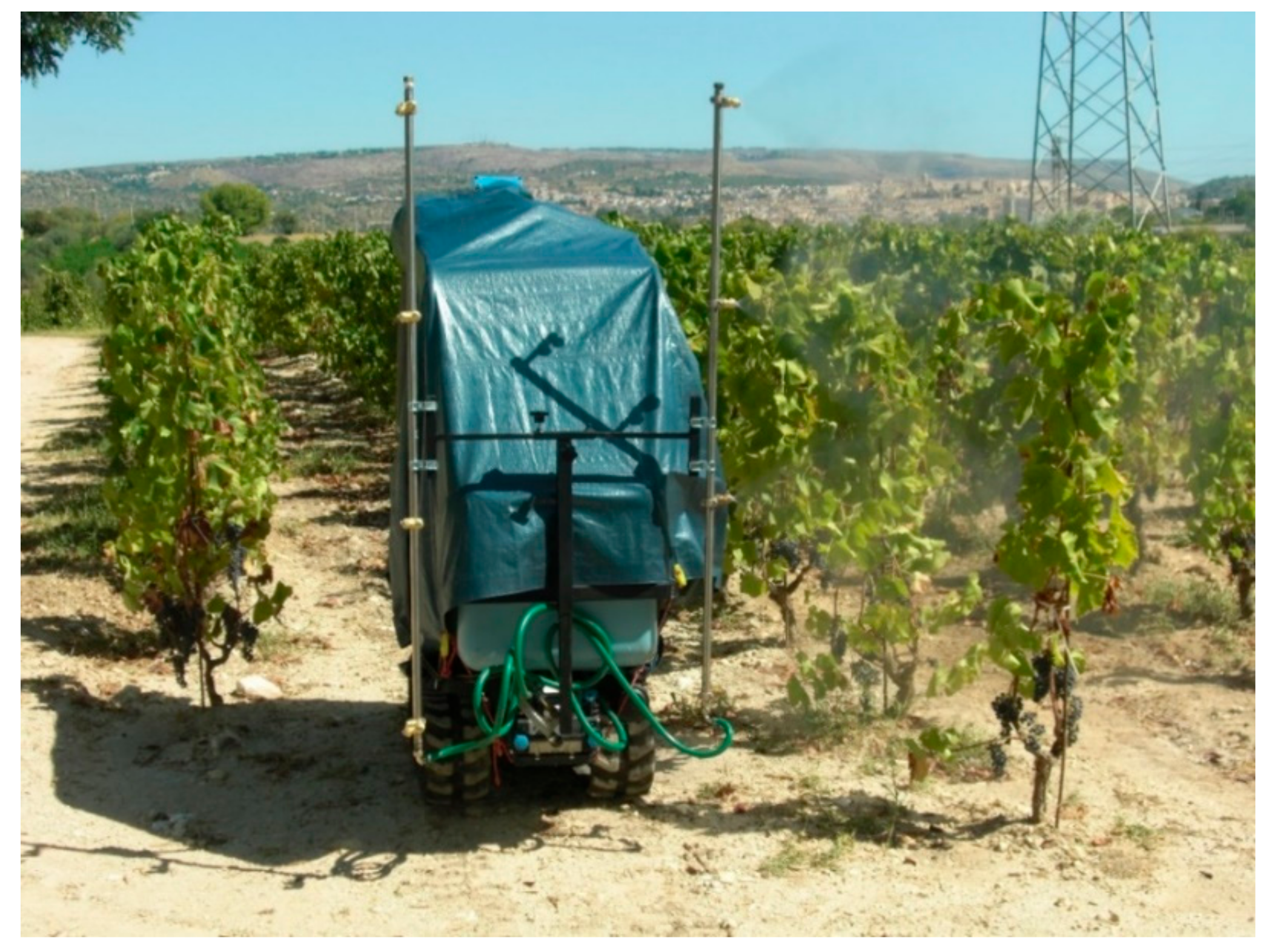
In order to evaluate the performance of the system, several trials were performed in two different scenarios: greenhouses and vineyards. In particular, the trials were carried out in a greenhouse in Southern Sicily near Scoglitti (Ragusa, Italy) (
Figure 1) and in two vineyards in Monte Serra—Viagrande (Catania, Italy) and in Noto (Syracuse, Italy) (
Figure 3). In the following, we report the results of a test executed in a greenhouse for tomato production in the Scoglitti area. We obtained similar results in the vineyard, as reported in [
23].
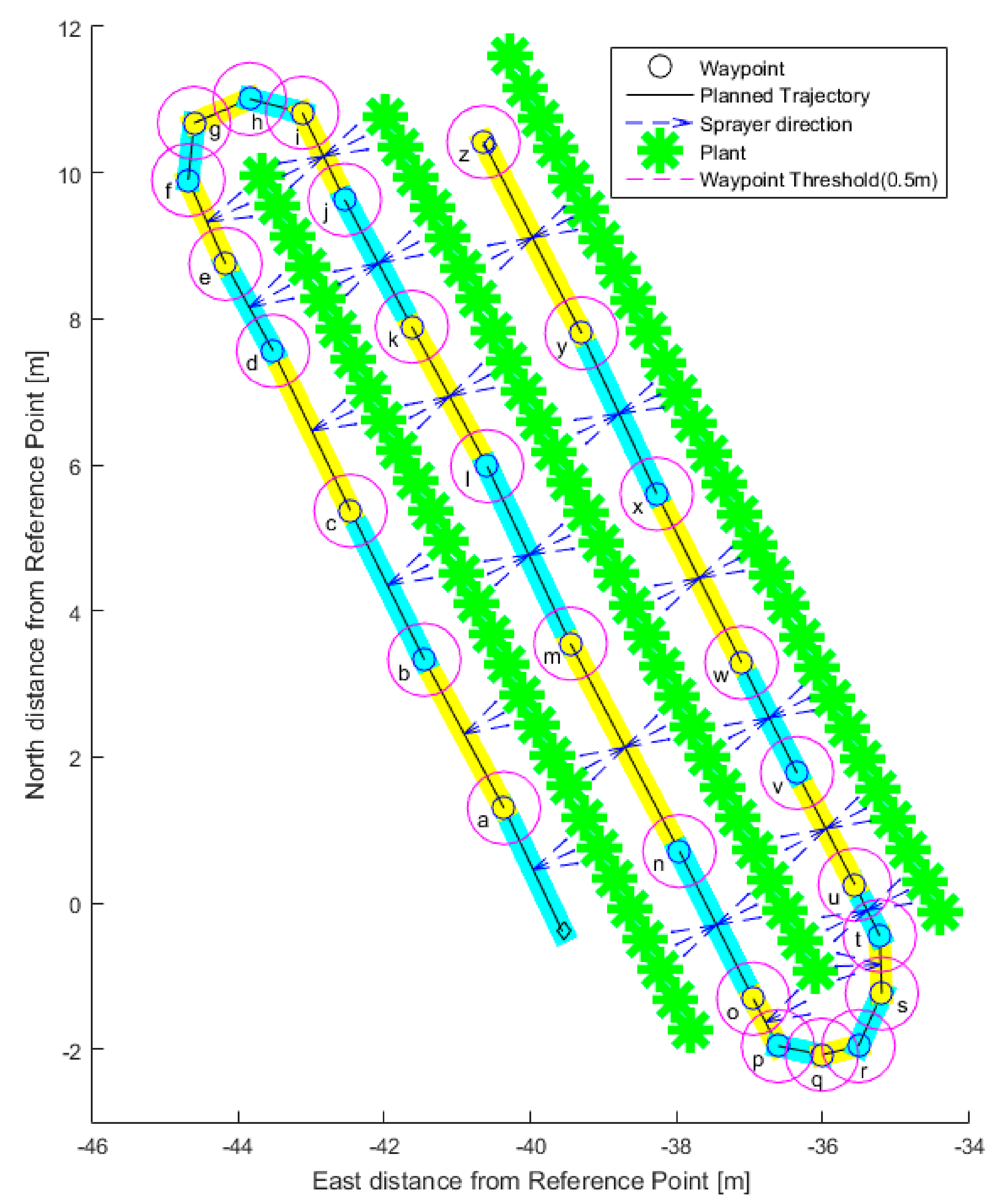
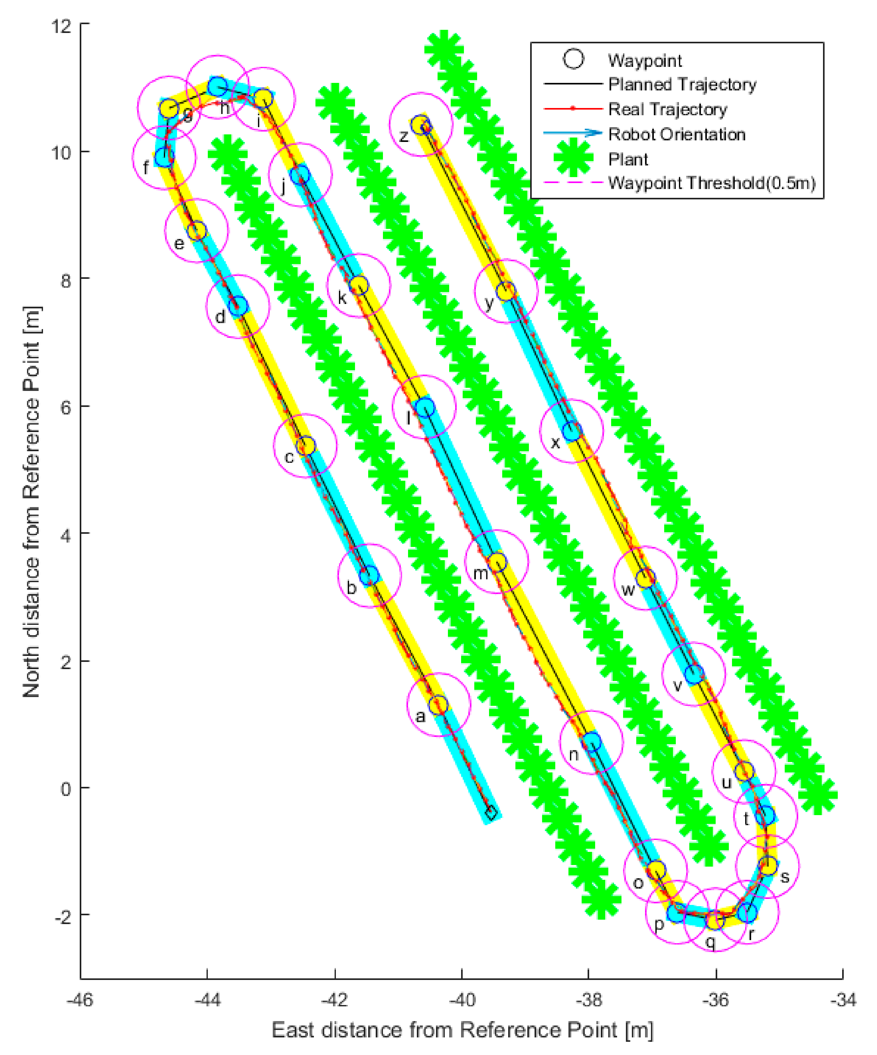
Figure 4 shows the desired trajectory, planned by driving the robot through the corridors before the mission and using the teach-and-repeat strategy. The graph reports only a small part of the whole trajectory, which involved more than the three represented corridors. The coordinates are expressed in meters, using a local tangent plane (LTP) projection with an ENU (east–north–up) coordinate frame.
The assigned WPs are represented as black circles and are indicated with letters from “a” to “z”.
Purple circles represent the waypoint radius: that is, when the vehicle enters the circle, the WP is considered reached and the robot moves to the next WP.
The green stars show the nominal positions of the plants; the real positions and the foliage volume are not represented in the figure.
The figure also shows the zones where the sprayers will be active and the side to spray (left and/or right bar of the spraying system).
Figure 5 reports the path executed by the robot: the red dots represent the recorded positions. As can be observed, the robot executed the mission as desired, taking into account the presence of obstacles: in the specific case, the vehicle slightly deviated from the assigned trajectory due to foliage (detected by the laser scanner) that invaded the corridor. The PFM compensated for that, modifying the robot trajectory.
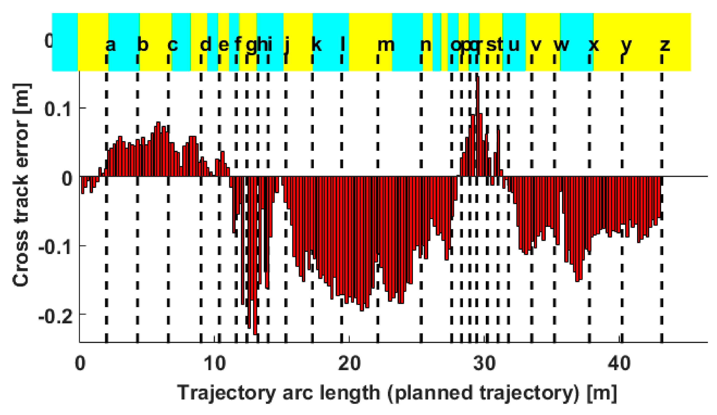
Figure 6 shows the cross-track error (i.e., the distance from the desired route) against the arc length of the trajectory. In particular, negative values of the error mean that the robot was on the right with respect to the vector between the origin and destination waypoints.
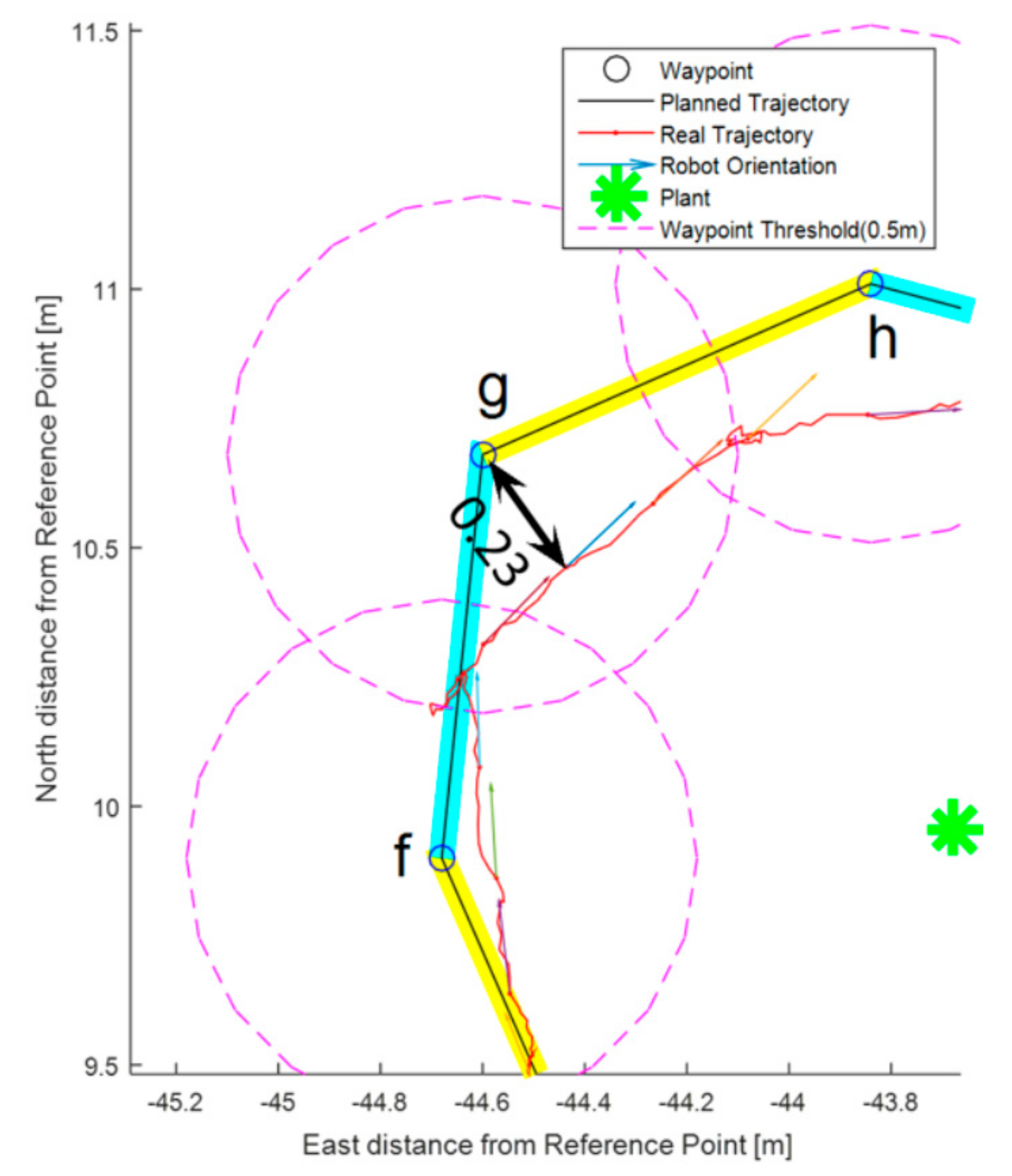
The maximum value of the error was 0.23 m: this error was due to the behavior of the system during the turns. In fact, as can be observed in
Figure 7, which reports path details, when the robot was approaching WP “g” and entered its circle, the waypoint was considered as reached and the robot pointed toward the next WP. Meanwhile, the error in the straight trajectories—especially in the second and the third corridors—was due to the thicker foliage of the plants of the central row with respect to the others.
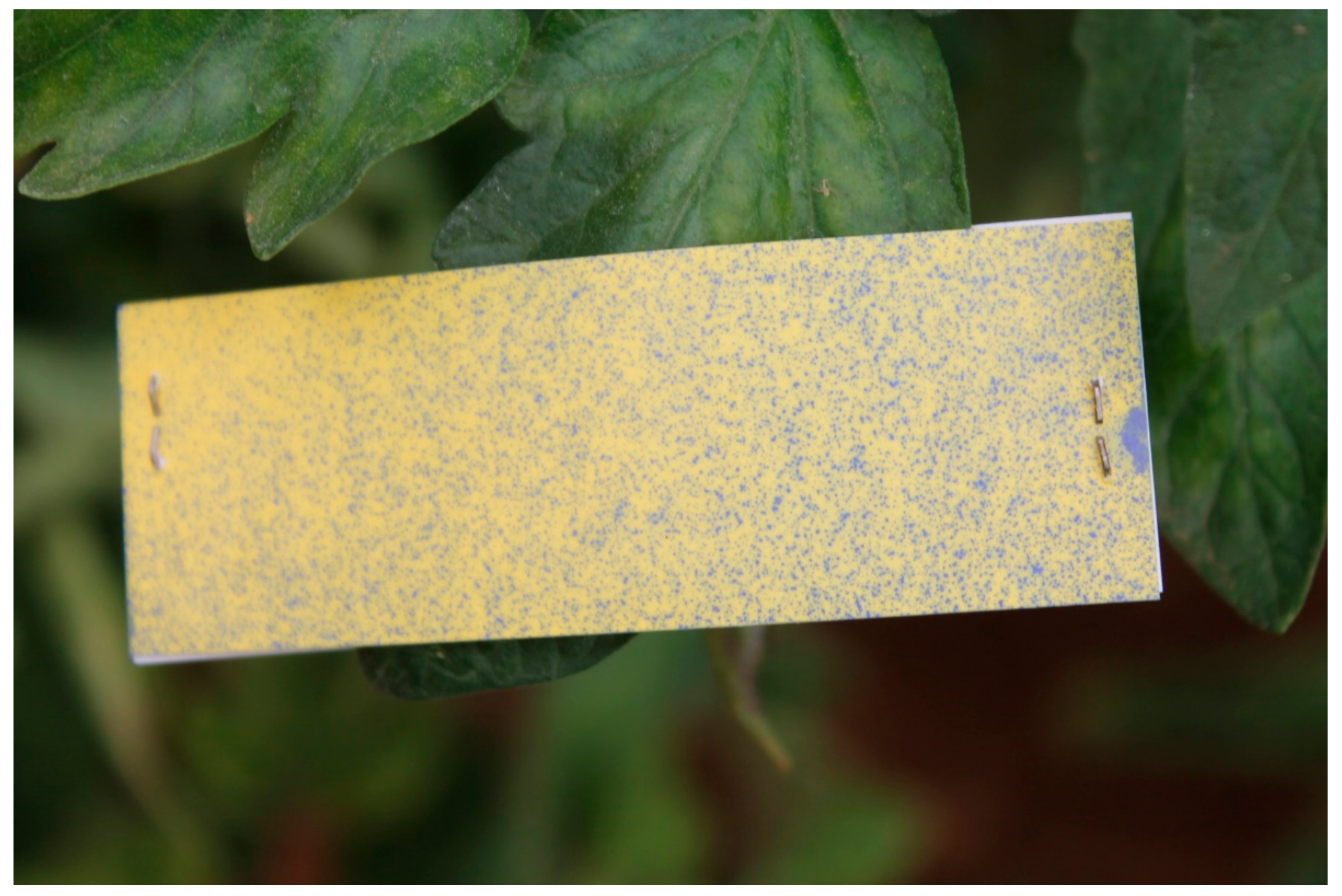
The performance of the spraying system was also preliminary evaluated. Standard procedures using water-sensitive papers (WSPs) were used to check for uniform droplets distribution along the robot path and at corridor ends. WSPs were placed at three different heights: on top of the plants (h), at 0.5 h and at 0.3 h. The chosen positions were at the beginning of the row, at the end of the row, and in the middle point of the row. Note that it is important to check the distribution at the beginning and at the end of the rows, since the robot may overspray the same plant during turns if the flow is not adequately controlled. Preliminary analysis of WSPs, performed as in [
27,
28,
29], showed a good performance of the system. Full numerical analysis of the WSPs has not yet been performed because the main goal of the present work was related to the robotic infrastructure of the whole smart sprayer: electrical tracked vehicle, related mechanical parts and power electronics, hydraulics, and electronics. The system has been labelled as a “precise sprayer” due to its hardware capabilities and the availability of a full set of actuators and sensors able to distribute a known quantity of chemicals.
Figure 8 illustrates one of the deployed WSPs. Since in our results there were no significant differences depending on the height, we only report one image.
4. Conclusions and Future Works
The interaction between the autonomous vehicle and the spraying management system is a solution with high technological content that allows safe and accurate autonomous spraying operations.
As demonstrated by the experimental results, the proposed architecture showed good performance, even in a scenario such as a greenhouse that could introduce GNSS signal attenuations and create multipath reflections. All the trials were performed without any significant degradation.
The robot autonomously carried out the assigned path between the rows for about 8 h, maintaining a sufficient safe distance from the plants. The smart spraying system regulated the amount of sprayed products in terms of quantity and selective activation of the nozzles based on the planned spraying treatments.
The compactness and robustness of the system paves the way for its adoption in environments where other normal agricultural machinery cannot operate, such as greenhouses, mountains, terraced and heroic cultivations. Further development and trials are needed to confirm the robustness of the system in more challenging environments than those presented here. However, from our preliminary tests, the platform shows good potential to be able to carry out the work also in harder conditions. Further tests in this direction will be done in the near future. Moreover, it must be noted that even though the proposed solution comprises a robotic approach to perform a specific agricultural task (spraying activities in this case), thanks to its modularity, other applications could be investigated in the future (e.g., harvesting, pruning, powder distribution, weed removal, soft tilling). Therefore, the potential applications could be expanded by the high flexibility of the proposed platform in relation to the various possible configurations. Indeed, a future system could be customizable through the use of specific tools that allow different types of tasks to be performed. Although the basic architecture will remain unaltered (i.e., a robotic platform equipped with an independent navigation system), any particular application could be developed through the addition of further equipment and tools.
At the moment, we are working on a software tool for the automatic planning of the whole mission: a georeferenced map of the plantation will be used to automatically generate the trajectory, with the aim of efficiently covering the area of interest. Moreover, the tool will plan the amount of product to spray, in terms of quantity and selective activation of the nozzles on the basis of presence of the plant, foliage density, type of crop, and forward speed of the machine.


 ,
, 


