Article

A Note on the Sound Absorption Characteristics of Microperforated Panels with Non-Circular Holes

Environmental Acoustics Laboratory, Department of Architecture, Graduate School of Engineering, Kobe University, Rokkodai, Nada, Kobe 657-8501, Japan
*
Author to whom correspondence should be addressed.
Acoustics 2025, 7(3), 57; https://doi.org/10.3390/acoustics7030057
Submission received: 9 April 2025 / Revised: 2 September 2025 / Accepted: 12 September 2025 / Published: 16 September 2025

Abstract

This study examines the characteristic parameters required for non-circular-hole microperforated panels (MPPs) to achieve sound absorption performance comparable to that of conventional circular-hole MPPs. Through numerical analysis, the flow resistivity and perforation ratio were found to be key parameters influencing the absorption characteristics of MPPs with square and equilateral triangular holes. The results indicate that for square-hole MPPs, matching either the flow resistivity alone or both the flow resistivity and perforation ratio to those of circular-hole MPPs leads to similar sound absorption characteristics. In contrast, for equilateral triangular-hole MPPs, both the above parameters must be matched to ensure comparable performance. Furthermore, this study explores MPPs incorporating a combination of circular and non-circular holes. It was confirmed that by appropriately matching the flow resistivity and perforation ratio, such mixed-hole MPPs can achieve sound absorption characteristics similar to those of MPPs composed solely of circular holes. These findings contribute to the broader design possibilities of MPPs, providing a foundation for optimising hole geometries in practical applications where manufacturing constraints or aesthetic considerations may necessitate non-circular hole patterns.

1. Introduction

The microperforated panel (MPP) is designed with an air cavity and a rigid backing, featuring a thin plate or film of arbitrary material with a thickness of less than 1 mm, perforated with numerous fine holes, typically with a diameter of approximately 1 mm or less at a perforation ratio of typically 1% or less. This configuration forms a Helmholtz-type resonator, where the combination of micro-perforations and the air cavity enables sound absorption. Generally, circular holes are arranged at uniform hole intervals [1,2].
The microperforated panel (MPP) was developed by Maa in the 1970s [3], and subsequently, he published predictive theories for its sound absorption characteristics and design theories [4,5,6]. Initially, the MPP was used in its classical application as a Helmholtz-type resonant sound absorber, as proposed by Maa. However, numerous studies have also been conducted on its applied forms, including its use as a space sound absorber [7,8,9,10,11,12].
Regarding variations in the MPP itself, recent studies have focused on heterogeneous MPPs. Lee et al. proposed a dot-art MPP, in which holes are arranged not in a uniformly spaced manner but to create illustrations or patterns [13]. In this case, the holes are positioned according to the design of the pattern and are therefore not uniformly spaced as in conventional MPPs. Consequently, they reported that conventional MPP prediction theories, such as Maa’s theory, cannot accurately predict the sound absorption characteristics of these structures.
On the other hand, studies on predictive theories for heterogeneous MPPs, including cases where holes of different diameters are mixed, have been conducted by Carbajo et al. [14] and Kusaka et al. [15]. Furthermore, Sakagami et al. proposed a design for dotted-art MPPs with improved predictability by distributing holes across the entire surface in addition to the pattern itself [16]. In addition to the above, other issues to be considered include predicting the sound absorption characteristics of MPPs that have become inhomogeneous due to variations in hole shape and dimensions caused by the effects of manufacturing accuracy. In particular, it has been pointed out that when MPPs and perforated plates are made by additive manufacturing, the effect of manufacturing accuracy on the acoustic properties is remarkable [17].
Apart from these studies, various efforts have been made to explore MPP designs that differ from conventional ones. For example, recent studies have explored novel MPP designs that differ even further from conventional MPPs. Miasa et al. [18] conducted an experimental study on MPPs with multiple hole sizes, while research on MPPs with non-circular holes has also emerged. Examples include studies on MPPs with square and equilateral triangular holes by Ning et al. [19] and investigations of petal-shaped perforations by Xu et al. [20].
Further investigation is needed for cases involving non-circular holes. For example, the findings of such studies could be utilised in situations where the holes are not perfectly circular due to manufacturing accuracy and exhibit irregularities.
From this perspective, this study first examines the sound absorption characteristics of MPPs with non-circular holes. Specifically, numerical analyses are conducted to determine and compare the characteristics of MPPs with square and equilateral triangular holes in addition to circular ones. In particular, the conditions under which MPPs with square and equilateral triangular holes exhibit the same sound absorption characteristics as those with circular holes are derived from numerical analysis results.
Furthermore, numerical analysis is performed on MPPs in which circular and non-circular holes coexist, and the extent to which their sound absorption characteristics differ from those of MPPs with only circular holes is evaluated using statistical indicators. The case where circular and non-circular holes coexist is expected to provide insights into the differences in sound absorption characteristics arising from variations in hole shapes due to manufacturing accuracy, as mentioned above. This study aims to obtain fundamental insights from a practical perspective. To focus on qualitative considerations, such as the effect of different hole shapes on the sound absorption coefficient, and to save computational cost, it targets cases featuring relatively large holes.

2. Sound Absorption Characteristics of Non-Circular MPPs

In this section, we present the fundamental sound absorption characteristics of micro-perforated panels (MPPs) with non-circular holes (specifically, square and equilateral triangular holes). Additionally, we investigate parameter-setting methods to approximate their absorption characteristics to those of conventional MPPs with circular holes. This study focuses on two types of non-circular holes: square and equilateral triangular.
As a specific approach, we set the hole dimensions and other parameters so that one or two characteristic parameters match between non-circular-hole MPPs and circular-hole MPPs. By comparing their sound absorption characteristics, we evaluate the degree of agreement. The characteristic parameters considered in this study include: (1) the hydraulic radius of a hole (defined as re = 2S/L, where S is the area of a hole and L is the hole perimeter), (2) the hole flow resistivity, which is the flow resistivity of a single hole [21], (3) the panel flow resistivity, which is the flow resistivity of the panel on the whole, and (4) the perforation ratio of the MPP. These characteristic parameters are matched by adjusting two parameters: the hole dimensions and the centre-to-centre distance of holes (hereinafter referred to as the hole interval).
In this study, we examine four cases, as summarised in Table 1 below.

2.1. Model for Simulation (Single Hole Cases)

The analysis was conducted using the Pressure Acoustics Module of COMSOL Multiphysics® Ver. 6.2 [22]. The constructed model is shown in Figure 1a–c. A single hole of an MPP was modelled and was placed within a waveguide with a square cross-section. The cross-sectional dimensions were set to 20 mm × 20 mm, corresponding to the hole interval, with a backing air layer thickness of 20 mm and an MPP thickness of 1 mm.
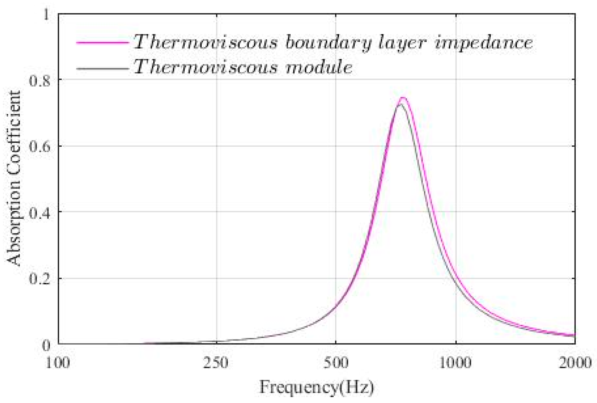
Additionally, a background sound field was defined, assuming a 200 mm-long incident sound field with a plane wave normally incident on the MPP. A Perfectly Matched Layer (PML) was applied to the boundary at the top end of the waveguide, i.e., the background sound field. The other boundaries were assumed to be rigid. The Thermoviscous Boundary Layer Impedance condition was assigned to the hole interior surfaces as well as to the front and back surfaces of the MPP. The Thermoviscous Boundary Layer Impedance condition adds the losses due to thermal and viscous dissipation in the acoustic boundary layers at a wall. The condition is applicable in cases where boundary layers are not overlapping. That is, it is not applicable in a very narrow waveguide (with dimensions comparable to the boundary layer thickness) or on very curved boundaries. In the present cases in which the dimension of the hole is larger than 1 mm, the thickness of the thermal boundary layer is around 0.1 mm at 500 Hz [22,23,24,25,26]. Therefore, the overlap is assumed to be not so severe. In order to confirm the accuracy of this condition, the solutions are compared with those derived by COMSOL’s thermoviscous acoustic interfaces. (See Appendix A for details).
The meshing was performed so as to ensure computational accuracy; a swept mesh was applied to the regions near the front and back surfaces of the MPP. Regarding the inside of the hole, finer meshing is applied as much as possible to consider the effect of the hole edges. A free tetrahedral mesh was used, and for circular-hole MPPs, the maximum element size was set to one-third of the hole radius, while for non-circular-hole MPPs, it was set to one-twelfth of the hole side length. For the front and back surfaces of the MPP, the mesh size was set to one-half of the hole dimension. In other regions, a free tetrahedral mesh was also used, with a maximum element size of one-fifth of the wavelength at the upper frequency limit of 4000 Hz (approximately 17.19 mm).
The maximum element size depends on the hole dimensions; thus, the total number of elements and degrees of freedom varied significantly depending on the hole size. In this analysis, the number of elements ranged from 28,729 to 1,013,384, and the degrees of freedom ranged from 63,763 to 1,909,417. The analysis was conducted in the frequency range of 100 Hz to 4000 Hz, with a resolution of 1/24 octave.

2.2. Evaluation Method

In order to evaluate the degree of agreement between the sound absorption characteristics of the circular-hole MPP and the non-circular-hole MPP, the following numerical indices are defined for the peak frequency, the peak sound absorption coefficient, and the difference in sound absorption coefficient over the entire frequency band of the two.
Relative deviation of the peak frequency of the sound absorption coefficient.
f d i f f e r e n c e % = f n o n c i r c u l a r   f c i r c u l a r f c i r c u l a r × 100
Relative deviation of the maximum sound absorption coefficient
α d i f f e r e n c e % = α n o n c u r c u l a r α c i r c u l a r α c i r c u l a r × 100
RMS deviation of the sound absorption coefficient
R M S = 1 n i = 100 4000 α n o n c i r c u l a r , i α c i r c u l a r , i 2
where α c i r c u l a r and f c i r c u l a r are the peak absorption coefficient and peak frequency of the circular MPP, and α n o n c i r c u l a r and f n o n c i r c u l a r are those of the non-circular MPP. The subscript i associates with frequency, i Hz.
α n o n c i r c u l a r , i denotes the sound absorption coefficient at i Hz for the irregular hole MPP, while α c i r c u l a r , i signifies the sound absorption coefficient at i Hz for the circular-hole MPP. The number of sound absorption coefficient data analysed is denoted by n, and the sound absorption coefficient was calculated at every 1/24th of an octave from 100 Hz to 4000 Hz. Therefore, n = 129. The sign of relative deviations is indicated by a ± symbol; however, in the subsequent comparisons and discussions, the sign was disregarded in principle and the absolute values were evaluated as either large or small.

2.3. Degree of the Agreement of Sound Absorption Characteristics

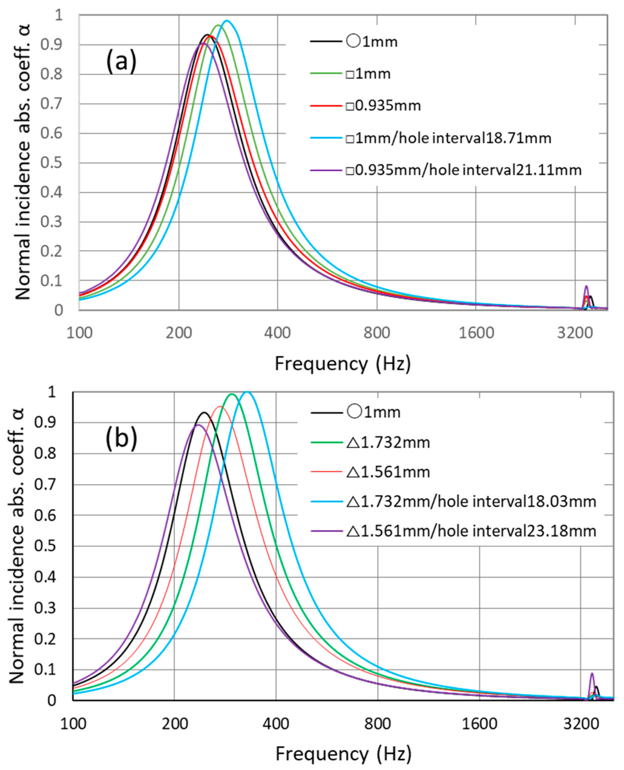
In Figure 2a,b, the sound absorption characteristics of a circular-hole MPP and a non-circular-hole MPP are shown, with each characteristic parameter matched. The matched characteristic parameters are as follows: hydraulic radius (green), hole flow resistivity (red), hydraulic radius and panel flow resistivity (light blue), hole flow resistivity and perforation ratio (purple). For comparison, results for a 1 mm circular-hole MPP are shown (black). The findings reveal that the peak sound absorption coefficient and peak frequency exhibit an increase in response to the matching of the flow resistivity of the hole, the matching of the hydraulic radius, and the matching of the hydraulic radius and the overall flow resistivity, in that order.
The reference values for the difference in the deviation index to determine whether the same sound absorption characteristics as the circular-hole MPP can be obtained when the respective characteristics are matched are 10% for the relative deviation fdifference of the peak frequency of the sound absorption coefficient and the relative deviation αdifference of the peak sound absorption coefficient, and 0.1 for the RMS deviation of the sound absorption coefficient. When these reference values are exceeded, a clear visual deviation can be observed between the sound absorption characteristics of the circular-hole MPP and the non-circular-hole MPP whose characteristics are matched to those of the circular-hole MPP. Therefore, it was judged possible to obtain sound absorption characteristics equivalent to those of the circular-hole MPP by matching the characteristics if the deviation indices for all three did not exceed these reference values when certain characteristics were matched. The deviation indices for the non-circular-hole MPPs with each characteristic matched to the 1 mm diameter circular-hole MPP are shown in Table 2 and Table 3. From these tables it can be seen that the characteristics for which a good match of the sound absorption characteristics can be obtained by matching the circular-hole MPPs are the flow resistivity of the hole; the flow resistivity of the hole and the perforation ratio for the square-hole MPPs; and the flow resistivity of the hole and the perforation ratio for the equilateral triangular hole MPPs.

3. MPPs with a Mixture of Non-Circular and Circular Holes

In this section, we investigate whether a microperforated panel (MPP) with a mixture of circular and non-circular holes can achieve acoustic absorption characteristics equivalent to those of an MPP composed solely of circular holes. This investigation is based on the results from the previous section, which demonstrated that by appropriately setting the characteristic parameters of non-circular-hole MPPs, their sound absorption properties can be made close to those of circular-hole MPPs.
Based on the findings from the previous section, we examine the following cases:
  • For MPPs with a mixture of circular and square holes, we consider two cases: 1 and 2.
  • For MPPs with a mixture of circular and equilateral triangular holes, we consider case 1.
Thus, the cases analysed are as follows:
  • When the non-circular holes are designed to match both the flow resistivity and perforation ratio of the circular-hole MPP.
  • When the non-circular holes are designed to match only the flow resistivity of the circular-hole MPP.
As in the previous section, the analysis is conducted using the Pressure Acoustics Module of COMSOL Multiphysics® Ver. 6.2.

3.1. Model for Simulation

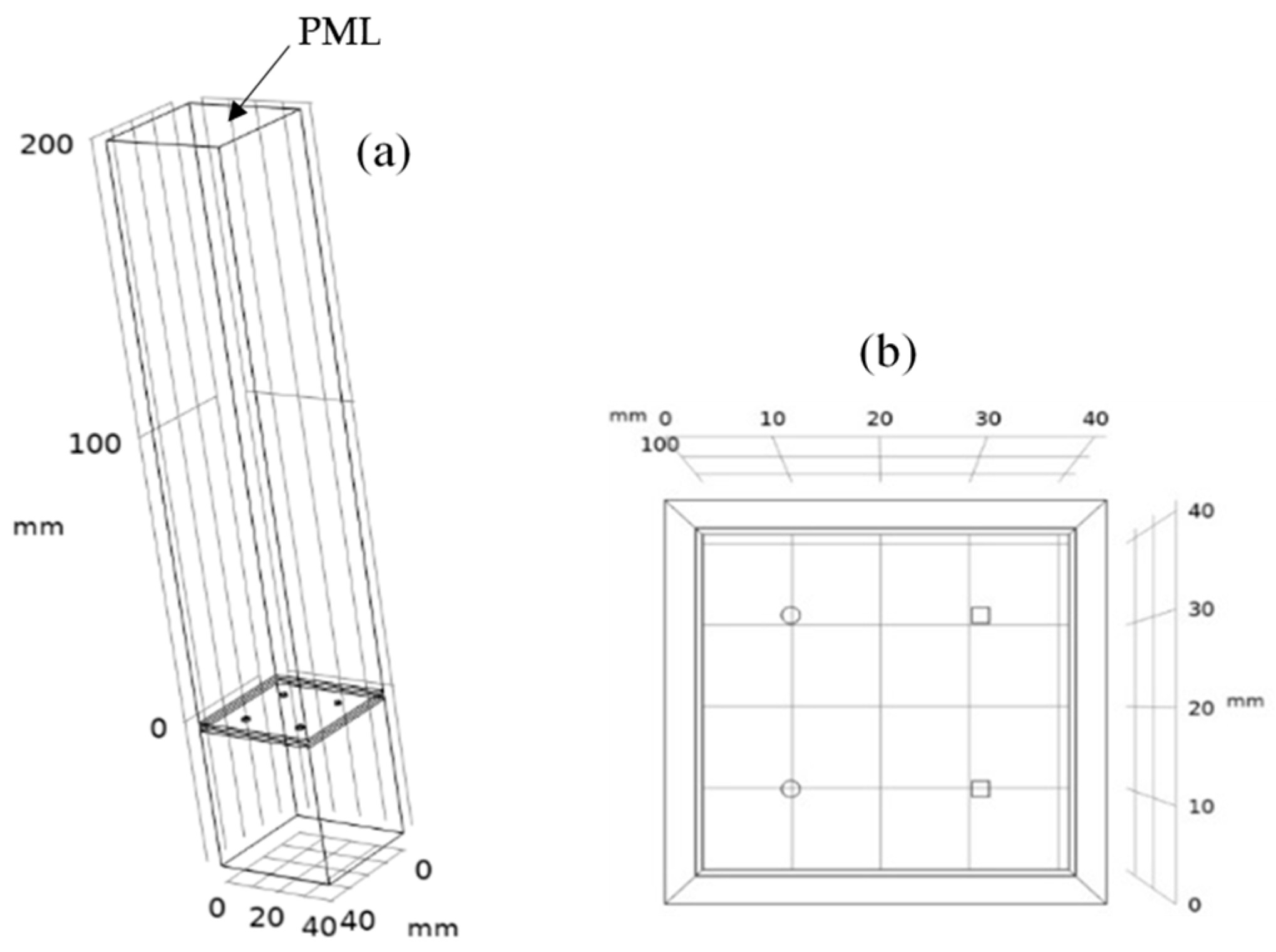
As shown in Figure 3, a microperforated panel (MPP) with two circular holes and two non-circular holes arranged at equal intervals is placed inside a square cross-section waveguide. The cross-section length is set to twice the hole interval, and other conditions are the same as in the previous section. The mesh division is performed using the meshing function of COMSOL Multiphysics®.
The mesh settings were the same as those used for the model in Section 2.1.
This setting is necessary because, when matching the characteristic parameters, the radius of the circular holes in an MPP with mixed circular and non-circular holes is, in many cases, smaller than the side length of the non-circular holes. Therefore, setting the maximum element size based on the smaller dimension is essential for maintaining computational accuracy.
For other regions, a free tetrahedral mesh is used, with the maximum element size set to one-fifth of the wavelength at the upper analysis limit of 4000 Hz, which is approximately 17.19 mm. As in Section 2, since the maximum element size depends on the hole dimensions, the total number of elements and degrees of freedom vary significantly depending on the hole size. In this analysis, these values ranged from 143,157 to 1,115,580 elements and 309,670 to 2,458,872 degrees of freedom, respectively. The simulations were conducted over a frequency range of 100 Hz to 4000 Hz, with calculations performed at 1/24-octave intervals.

3.2. Results and Discussion

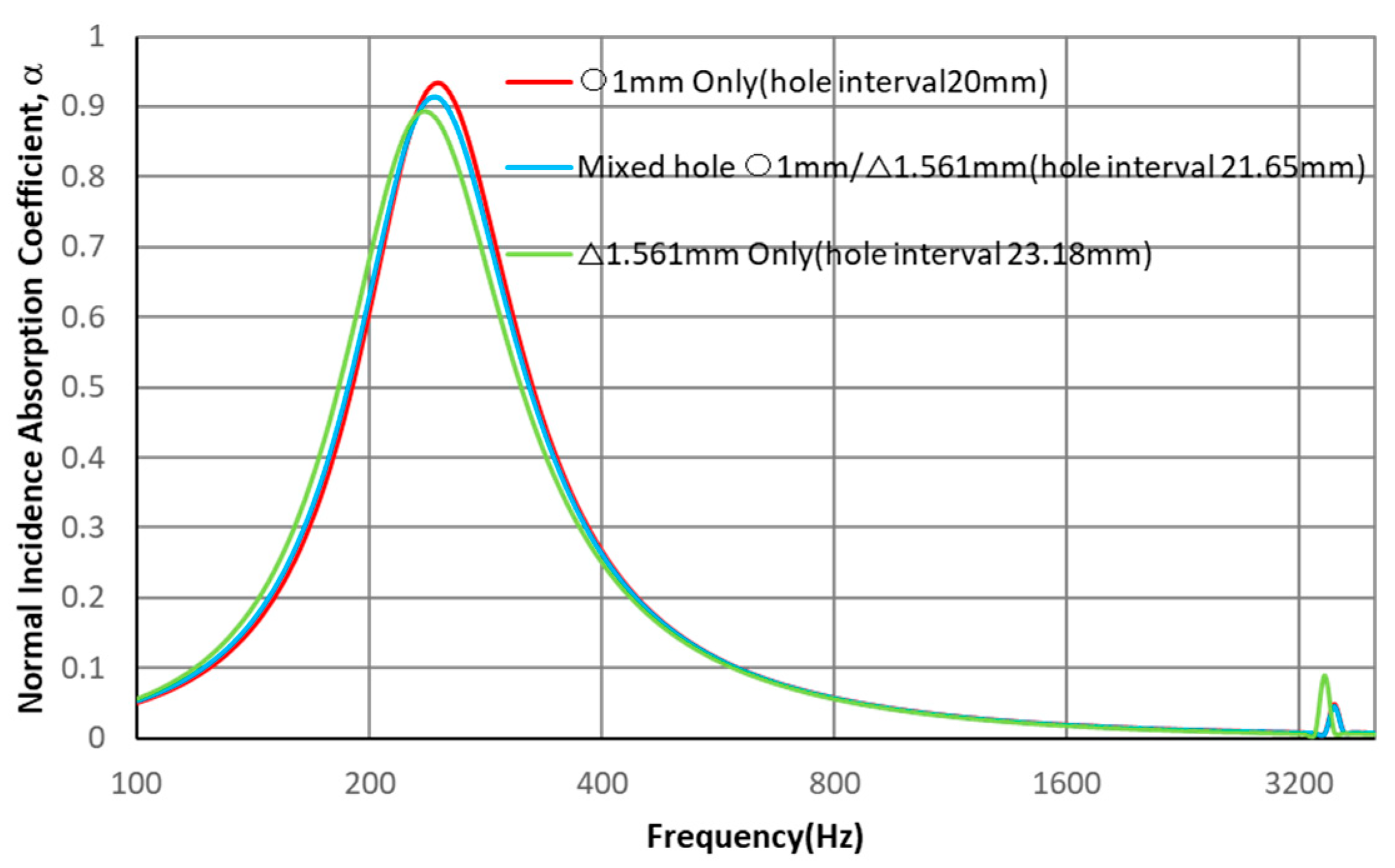
An example of the absorption characteristics of an MPP with circular and non-circular holes (hereafter mixed-hole MPP) is shown in Figure 4. In this example, a mixed-hole MPP with 1 mm diameter circular holes and equilateral triangular holes (side 1.561 mm, hole interval 21.65 mm) is compared with an MPP with 1 mm circular holes only, and an MPP with equilateral triangular holes (side 1.561 mm, hole interval 23.18 mm) only. As is observed, by mixing non-circular holes, the absorption characteristics slightly deviate from those of an MPP with circular holes only. In this case, the characteristics of the mixed-hole MPP are lower than those of the MPP with circular holes only and higher than those of the MPP with triangular holes only. Later, we discuss the deviation due to the effect of the combination with non-circular holes quantitatively by the indices presented before.
Table 4 presents an index of deviation in the sound absorption characteristics of a microperforated panel (MPP) with a combination of circular and square holes, where the square holes have the same flow resistivity and perforation ratio as the circular holes. Table 5 provides an index of deviation in the sound absorption characteristics of an MPP with a combination of circular and equilateral triangular holes, where the triangular holes have the same flow resistivity and perforation ratio as the circular holes. Table 6 presents an index of deviation in the sound absorption characteristics of an MPP with a combination of circular and square holes, where the square holes have the same flow resistivity as the circular holes.
From Table 4, Table 5 and Table 6, it is evident that the deviation in the sound absorption characteristics of MPPs with a combination of circular and non-circular holes is small compared to that of circular-hole MPPs.
Furthermore, from Table 4 and Table 5, it can be observed that the sound absorption coefficient of MPPs with a combination of circular and non-circular holes, where the non-circular holes have the same flow resistivity and perforation ratio as the circular holes, is approximately the intermediate value between the corresponding circular-hole MPPs and non-circular-hole MPPs across the entire frequency range.
In other words, if the sound absorption characteristics of the corresponding circular-hole MPP and non-circular-hole MPP are known, the sound absorption characteristics of the MPP with a combination of circular and non-circular holes can be estimated as an intermediate value between them. Therefore, it has been found that a more detailed prediction of the sound absorption characteristics is possible.

4. Concluding Remarks

In this study, the characteristic parameters that should be matched to achieve sound absorption performance comparable to that of circular-hole MPPs for non-circular-hole MPPs were identified through numerical analyses by FEM. In the analyses, as characteristic parameters to match, the following parameters and combinations of parameters were chosen: hydraulic radius of the hole, hole flow resistivity, hydraulic radius and panel flow resistivity, and hole flow resistivity and perforation ratio. In order to control them, the hole dimensions and hole intervals were adjusted. The sound absorption characteristics of a non-circular-hole MPP with the aforementioned characteristic parameters matched to those of a circular-hole MPP were analysed numerically using FEM and compared with those of a circular-hole MPP. The degree of agreement between the two was evaluated by the relative error of the peak frequency, the relative error of the peak value, and the RMS error of the sound absorption coefficient at all frequencies.
As a result, it was found that for square-hole MPPs, matching the hole flow resistivity, or both the hole flow resistivity and perforation ratio, to that of circular-hole MPPs leads to a good match in terms of sound absorption characteristics. Similarly, for equilateral triangular-hole MPPs, matching both the hole flow resistivity and perforation ratio to those of circular-hole MPPs ensures a good match in terms of sound absorption characteristics.
Furthermore, it was confirmed that by applying this parameter matching, MPPs with a combination of circular and non-circular holes can achieve sound absorption characteristics similar to those of MPPs composed solely of circular holes. The sound absorption characteristics of the mixed-hole MPP are approximately intermediate between those of the MPP with circular holes only and those of the MPP with non-circular holes.
These findings not only provide a basis for the design of non-circular-hole MPPs and the investigation of their properties but also provide practical understanding of the effects on sound absorption properties of, for example, non-circular hole shapes in the manufacturing process, especially errors caused by problems of manufacturing accuracy in the production process, such as those seen in additive manufacturing.

Author Contributions

Conceptualization, K.S.; methodology, K.S.; software, S.A.; validation, K.S., S.A.; formal analysis, K.S.; investigation, S.A.; resources, K.S.; data curation, S.A.; writing—original draft preparation, K.S.; writing—review and editing, K.S.; visualisation, S.A.; supervision, K.S.; project administration, K.S.; funding acquisition, K.S. All authors have read and agreed to the published version of the manuscript.

Funding

This research received no external funding.

Institutional Review Board Statement

Not applicable.

Informed Consent Statement

Not applicable.

Data Availability Statement

The original contributions presented in this study are included in the article. Further inquiries can be directed to the corresponding author.

Conflicts of Interest

The authors declare no conflicts of interest.

Appendix A. Comparison of the Results Using the Thermoviscous Boundary Layer Impedance and Those Using the Thermoviscous Acoustics Interfaces
The COMSOL thermoviscous boundary layer impedance used in the present study is a useful method to save computational cost when analysing acoustic problems considering thermoviscous losses, but it is a simplified treatment and is known to introduce calculation errors, especially when thermoviscous boundary layers overlap due to small pores or complex pore geometry [17]. On the other hand, thermoviscous acoustics interfaces solve the linearised Navier–Stokes equation in quiescent background conditions, solving the continuity, momentum, and energy equations. Therefore, it is considered that, using these interfaces with fine meshes, it should be possible to obtain a reasonably good result.
The thicknesses of the viscous and thermal boundary layers, δvisc and δtherm, respectively, can be solved analytically for plane wave problems and are given by [22,23,24,25,26]
δ v i s c = 2 μ ω ρ 0 δ ,   δ t h e r m = 2 k ω ρ 0 C p
For air, the δvisc is 0.22 mm at 100 Hz, 20 °C and 1 atm. As can be seen from the above equations, both the viscous and thermal boundary layer thicknesses are large at low frequencies. In air, the thickness of the thermal boundary layer is around 0.1 mm at around 500 Hz. Therefore, for rather higher frequencies, if the hole size is relatively large (e.g., 1 mm or more per side), the error due to the overlapping boundary layer is expected to be relatively small.
This section compares the results of the analyses using the non-approximation thermoviscous acoustic interface with those of the analysis using the present thermo-viscous boundary layer impedance, both in COMSOL Multiphysics Pressure Acoustics Module, and attempts to see the degree of accuracy that can be achieved from the difference between the two results.
Considering the shape, it is considered that equilateral triangular holes would have the most significant boundary layer overlap. Therefore, in this section, we examine the case of equilateral triangular holes in MPPs. We analysed the normal incidence sound absorption coefficient of MPPs with equilateral triangular holes of 1, 2, and 3 mm sides using COMSOL Multiphysics® (Pressure Acoustics Module). Through this, we obtained results using both the method employing thermoviscous boundary layer impedance and the method employing the thermoviscous acoustics interfaces, and compared the two. This provides a basic understanding of the extent of error introduced by thermoviscous boundary layer impedance.
The analysis model is the same as in Figure 1 (cross-sectional area of 20 mm square). Other than the hole dimensions, the parameters of the absorber are as follows: panel thickness 1 mm, hole separation 20 mm, and back air layer thickness 20 mm. The mesh and other details are the same as described in the main text (Section 2). Note that for the analysis using the thermoviscous acoustics interfaces, the mesh size was changed in steps, and it was confirmed that the results converged at r/12 (where r is the side length of the hole) within the hole. This means 0.083 mm when the hole side length is 1 mm, and 0.25 mm when the hole side length is 3 mm. Therefore, this mesh size was employed in the current consideration.
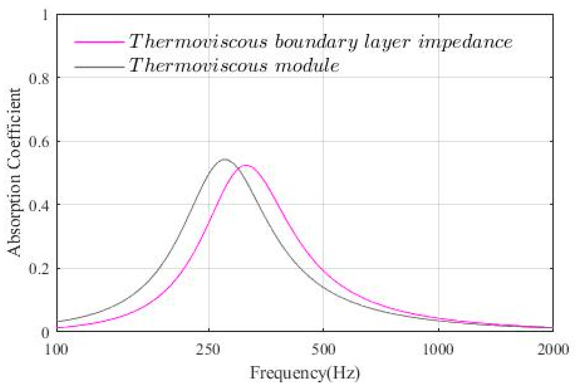
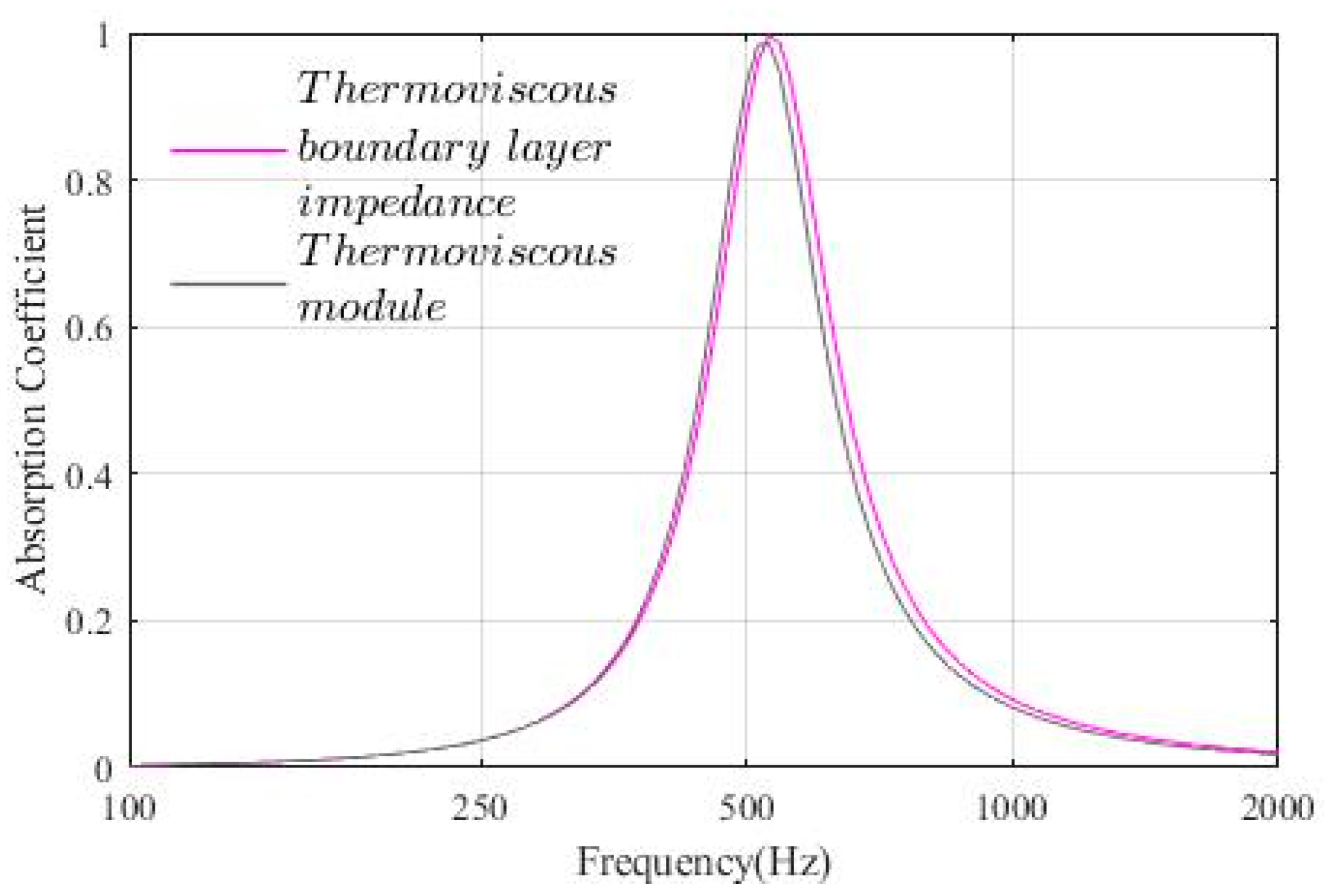
The results for the MPP with equilateral triangular holes with a side length of 1 mm are shown in Figure A1, those for a side length of 2 mm are shown in Figure A2, and those for a side length of 3 mm are shown in Figure A3.
Figure A1. Comparison of the normal incidence absorption coefficient of equilateral triangular hole MPP of side length 1 mm. Purple: results calculated by using thermoviscous boundary layer impedance; black: those calculated by using the thermoviscous acoustics module.
Acoustics 07 00057 g0a1
Figure A2. Comparison of the normal incidence absorption coefficient of equilateral triangular hole MPP of side length 2 mm. Purple: results calculated by using thermoviscous boundary layer impedance; black: those calculated by using the thermoviscous acoustics module.
Acoustics 07 00057 g0a2
Figure A3. Comparison of the normal incidence absorption coefficient of equilateral triangular hole MPP of side length 3 mm. Purple: results calculated by using thermoviscous boundary layer impedance; black: those calculated by using the thermoviscous acoustics module.
Acoustics 07 00057 g0a3
For a side length of 1 mm, the peak frequency and peak sound absorption coefficient were 475 Hz and 0.534 for the thermoviscous boundary layer impedance case and 437 Hz and 0.562 for the thermoviscous acoustics interface case, showing a small discrepancy. Errors of this magnitude are likely to be included in the discussion in the text, but this is a limitation of the method used in the present study and cannot be avoided in the present work.
On the other hand, the differences were even smaller for edge lengths of 2 mm and 3 mm, as can be seen in the figures. Considering Equation (A1) for the boundary layer thickness, it can be assumed that the larger the side length, the smaller the error, so that the overall qualitative conclusion seems to remain the same.

References

  1. Adams, T. Sound Materials: A Compendium of Sound Absorbing Materials for Architecture and Design; Frame Pub: Amsterdam, The Netherland, 2017; pp. 214–231. [Google Scholar]
  2. Herrin, D.; Liu, J.; Seybert, A. Properties and applications of microperforated panels. Sound Vib. 2011, 45, 6–9. [Google Scholar]
  3. Maa, D.-Y. Theory and design of microperforated panel sound-absorbing constructions. Sci. Sin. 1975, 17, 55–71. [Google Scholar]
  4. Maa, D.-Y. Microperforated-panel wideband absorbers. Noise Control Eng. J. 1987, 29, 77–84. [Google Scholar] [CrossRef]
  5. Maa, D.-Y. Potential of microperforated panel absorber. J. Acoust. Soc. Am. 1998, 104, 2861–2866. [Google Scholar] [CrossRef]
  6. Maa, D.-Y. Practical single MPP absorber. Int. J. Acoust. Vib. 2007, 12, 3–6. [Google Scholar] [CrossRef]
  7. Kang, J.; Fuchs, H.V. Predicting absorption of open weave textiles and micro-perforated membranes backed by an air space. J. Sound Vib. 1999, 220, 905–920. [Google Scholar] [CrossRef]
  8. Fuchs, H.V.; Zha, X. Acrylic-glass sound absorbers in the plenum of the Deutscher Bundestag. Appl. Acoust. 1997, 51, 211–217. [Google Scholar] [CrossRef]
  9. Fuchs, H.V.; Zha, X.; Zhou, X.; Drotleff, H. Creating low-noise environments in communication rooms. Appl. Acoust. 2001, 62, 1375–1396. [Google Scholar] [CrossRef]
  10. Zha, X.; Fuchs, H.V.; Drotleff, H. Improving the acoustic working conditions for musicians in small spaces. Appl. Acoust. 2002, 63, 203–221. [Google Scholar] [CrossRef]
  11. Sakagami, K.; Morimoto, M.; Koike, W. A numerical study of double-leaf microperforated panel absorbers. Appl. Acoust. 2006, 67, 609–619. [Google Scholar] [CrossRef]
  12. Sakagami, K.; Okuzono, T. Some considerations on the use of space sound absorbers with next-generation materials reflecting COVID situations in Japan: Additional sound absorption for post-pandemic challenges in indoor acoustic environments. UCL Open Environ. 2020, 2, e012. [Google Scholar] [CrossRef] [PubMed]
  13. Lee, H.P.; Kumar, S.; Aow, J.W. Proof-of-concept design for MPP acoustic absorbers with element of art. Designs 2021, 5, 72. [Google Scholar] [CrossRef]
  14. Carbajo, J.; Ramis, I.; Godinho, L.; Amado-Mendes, P. Assessment of methods to study the acoustic properties of heterogeneous perforated panel absorbers. Appl. Acoust. 2018, 133, 1–7. [Google Scholar] [CrossRef]
  15. Kusaka, M.; Sakagami, K.; Okuzono, T. A basic study on the absorption properties and their prediction of heterogeneous micro-perforated panels; A case study of micro-perforated panels with heterogeneous hole size and perforation ratio. Acoustics 2021, 3, 473–484. [Google Scholar] [CrossRef]
  16. Sakagami, K.; Kusaka, M.; Okuzono, T. A basic study on the design of dotted-art heterogeneous MPP sound absorbers. Acoustics 2022, 4, 588–608. [Google Scholar] [CrossRef]
  17. Sakagami, K.; Kusaka, M.; Okuzono, T.; Nakanishi, S. The effect of deviation due to the manufacturing accuracy in the parameters of an MPP on its acoustic properties: Trial production of MPPs of different hole shapes using 3D printing. Acoustics 2020, 2, 605–616. [Google Scholar] [CrossRef]
  18. Miasa, I.M.; Okuma, M.; Kishimoto, G.; Nakahara, T. An experimental study of a multi-size microperforated panel absorber. J. Sys. Des. Dynam. 2007, 1, 331–339. [Google Scholar] [CrossRef]
  19. Ning, J.F.; Ren, S.W.; Zhao, G.P. Acoustic properties of micro-perforated panel absorber having arbitrary cross-sectional perforations. Appl. Acoust. 2016, 111, 135–136. [Google Scholar] [CrossRef]
  20. Xu, Z.; He, W.; Peng, X.; Xian, F.; Lu, T.J. Sound absorption theory for micro-perforated panel with petal-shaped perforations. J. Acoust. Soc. Am. 2020, 148, 18. [Google Scholar] [CrossRef] [PubMed]
  21. Allard, J.F.; Atalla, N. Propagation of Sound in Porous Media: Modelling Sound Absorbing Materials, 2nd ed.; John Wiley & Son, Ltd.: Chichester, UK, 2009. [Google Scholar]
  22. COMSOL Documentation. Acoustics Module User’s Guide Ver. 6.3; COMSOL: Stockholm, Sweden, 2024. [Google Scholar]
  23. Jensen, M.H. COMSOL Blog, Theory of Thermoviscous Acoustics: Thermal and Viscous Losses. 2016. Available online: https://www.comsol.com/blogs/theory-of-thermoviscous-acoustics-thermal-and-viscous-losses (accessed on 11 September 2025).
  24. Pierce, A.D. Acoustics: An Introduction to Its Physical Principles and Applications; McGraw-Hill: New York, NY, USA, 1981; (rpt. 1989, Acoust. Soc. Am., NY, USA). [Google Scholar]
  25. Temkin, S. Elements of Acoustics; Acoustical Society of America: New York, NY, USA, 2001. [Google Scholar]
  26. Morse, P.M.; Ingard, K.U. Theoretical Acoustics; Princeton University Press: Princeton, NJ, USA, 1987. [Google Scholar]
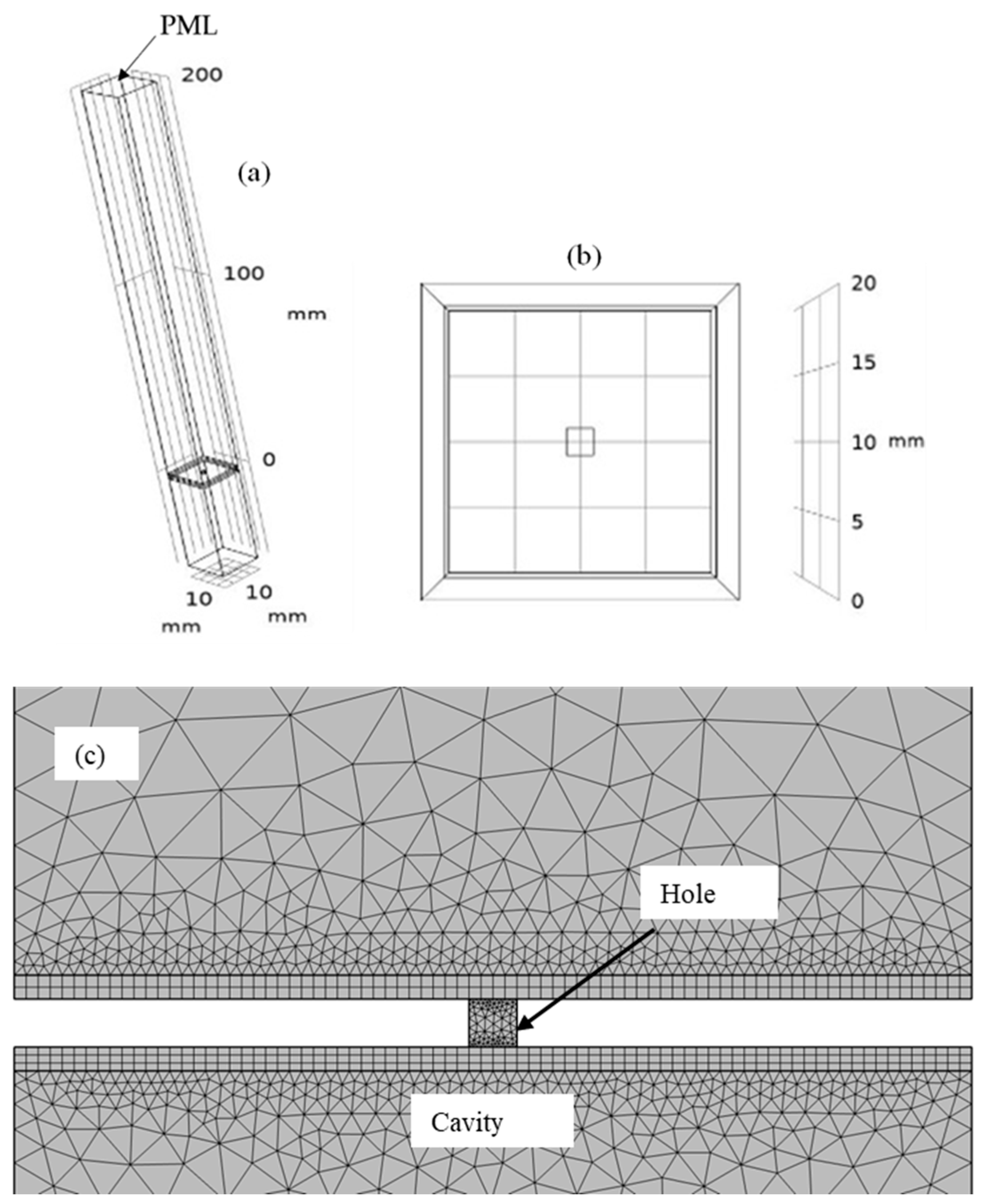
Figure 1. (a) Overall view of the model; (b) non-circular-hole MPP model viewed from above; (c) the close-up view of the model of the hole.
Acoustics 07 00057 g001
Figure 2. (a) Sound absorption characteristics of a 1 mm diameter circular-hole MPP and square-hole MPP with equal amounts of each characteristic parameter, and (b) Sound absorption characteristics of a 1 mm diameter circular-hole MPP and equilateral triangular hole MPP with equal amounts of each characteristic parameter. The matched characteristic parameters are as follows: hydraulic radius (green), hole flow resistivity (red), hydraulic radius and panel flow resistivity (light blue), hole flow resistivity and perforation ratio (purple). For comparison, results for a 1 mm circular-hole MPP are shown (black).
Acoustics 07 00057 g002
Figure 3. (a) Overall view of the model; (b) MPP model with a mixture of circular and non-circular holes, viewed from above.
Acoustics 07 00057 g003
Figure 4. An example of the absorption characteristics of a mixed-hole MPP. In this example, an MPP with a circular hole only (diameter 1 mm, hole interval 20 mm), an MPP with an equilateral triangular hole only (side 1.561 mm, hole interval 23.18 mm), and a mixed-hole MPP (1 mm circle and 1.561 mm triangle, hole interval 23.18 mm) are compared. These MPPs have the same hole flow resistivity and perforation ratio.
Acoustics 07 00057 g004
Table 1. Characteristic parameters to be matched to the circular-hole MPP and the controlled parameters of the non-circular-hole MPP.
Characteristic Parameters to Match the Circular-Hole MPPParameters of the Non-Circular-Hole MPP to be Operated
1Hydraulic radiusHole dimension
2Hole flow resistivity Hole dimension
3Hydraulic radius and panel flow resistivityHole dimension and interval
4Hole flow resistivity and perforation ratioHole dimension and interval
Table 2. Index of deviation of square-hole MPPs with each characteristic property matched to a 1 mm diameter circular-hole MPP.
Characteristic Parameter to Be Fixedfdifference (%)αdifference (%)RMS Deviation
Hydraulic radius+10.42+3.8060.050672
Hole flow resistivity+4.167−0.0430.024892
Hydraulic radius and panel flow resistivity+16.67+5.5810.083242
Hole flow resistivity and perforation ratio−1.667−2.5810.004727
Table 3. Index of deviation of equilateral triangular hole MPPs with each characteristic property matched to a 1 mm diameter circular-hole MPP.
Characteristic Parameter to Be Fixedfdifference (%)αdifference (%)RMS Deviation
Hydraulic radius+22.92+6.5590.104885
Hole flow resistivity+13.33+2.5160.067118
Hydraulic radius and panel flow resistivity+35.42+7.4840.149535
Hole flow resistivity and perforation ratio−1.667−3.9680.007807
Table 4. Index of deviation of absorption characteristics of MPPs with a mixture of square and circular holes with hole flow resistivity and perforation ratio matched to circular-hole MPPs.
Subject for Calculating Deviationfdifference (%)αdifference (%)RMS Deviation
Circular-hole MPP and mixed-hole MPP−0.627+2.9030.00477
Circular-hole MPP and square-hole MPP−3.639+5.7370.00701
Table 5. Index of deviation of sound absorption characteristics of MPPs with a mixture of equilateral triangular and circular holes with hole flow resistivity and perforation ratio matched to circular-hole MPPs.
Subject for Calculating Deviationfdifference (%)αdifference (%)RMS Deviation
Circular-hole MPP and mixed-hole MPP−1.413+1.2050.00631
Circular-hole MPP and equilateral triangular hole MPP−4.860+6.1210.01110
Table 6. Index of deviation of sound absorption characteristics of MPPs with a mixture of square and circular holes with hole flow resistivity matched to the circular-hole MPPs.
Subject for Calculating Deviationfdifference (%)αdifference (%)RMS Deviation
Circular-hole MPP and mixed-hole MPP−2.368−1.8350.00879
Circular-hole MPP and square-hole MPP+1.715+1.3420.01690
Disclaimer/Publisher’s Note: The statements, opinions and data contained in all publications are solely those of the individual author(s) and contributor(s) and not of MDPI and/or the editor(s). MDPI and/or the editor(s) disclaim responsibility for any injury to people or property resulting from any ideas, methods, instructions or products referred to in the content.