Article

Identifying Potential Leakage Zones in an Irrigation Supply Channel by Mapping Soil Properties Using Electromagnetic Induction, Inversion Modelling and a Support Vector Machine

1
School of Biological, Earth and Environmental Sciences, Faculty of Science, UNSW Sydney, Sydney, NSW 2052, Australia
2
Instituto Dom Luiz, Faculdade de Ciências da Universidade de Lisboa, Campo Grande, Ed. C1, Piso 1, 1749-016 Lisboa, Portugal
*
Author to whom correspondence should be addressed.
Soil Syst. 2020, 4(2), 25; https://doi.org/10.3390/soilsystems4020025
Submission received: 17 March 2020 / Revised: 14 April 2020 / Accepted: 16 April 2020 / Published: 22 April 2020
(This article belongs to the Special Issue Proximal Soil Sensing Applications)

Abstract

:
The clay alluvial plains of Namoi Valley have been intensively developed for irrigation. A condition of a license is water needs to be stored on the farm. However, the clay plain was developed from prior stream channels characterised by sandy clay loam textures that are permeable. Cheap methods of soil physical and chemical characterisations are required to map the supply channels used to move water on farms. Herein, we collect apparent electrical conductivity (ECa) from a DUALEM-421 along a 4-km section of a supply channel. We invert ECa to generate electromagnetic conductivity images (EMCI) using EM4Soil software and evaluate two-dimensional models of estimates of true electrical conductivity (σ—mS m−1) against physical (i.e., clay and sand—%) and chemical properties (i.e., electrical conductivity of saturated soil paste extract (ECe—dS m−1) and the cation exchange capacity (CEC, cmol(+) kg−1). Using a support vector machine (SVM), we predict these properties from the σ and depth. Leave-one-site-out cross-validation shows strong 1:1 agreement (Lin’s) between the σ and clay (0.85), sand (0.81), ECe (0.86) and CEC (0.83). Our interpretation of predicted properties suggests the approach can identify leakage areas (i.e., prior stream channels). We suggest that, with this calibration, the approach can be used to predict soil physical and chemical properties beneath supply channels across the rest of the valley. Future research should also explore whether similar calibrations can be developed to enable characterisations in other cotton-growing areas of Australia.

1. Introduction

The vertosols that characterise the extensive clay alluvial plains of Namoi Valley, New South Wales (NSW) make this a highly productive agricultural area. Up until the 1960s, their versatility enabled dryland wheat, sheep and beef cattle production [1]. The construction of Keepit Dam in the late 1960s provided water for irrigation, and today, Namoi Valley has been extensively developed for irrigated cotton farming. In the lower Namoi, this is mostly dependent on water supplied from Keepit Dam via the river. Moreover, a condition of an irrigation license is that the water needs to be stored on a farm. This requires supply channels and water storages. Between Narrabri and Wee Waa, many supply channels were constructed and traverse the plain from south to north. However, the clay plains were developed upon alluvial sediments from prior stream channels, which traverse this area in a west to north-west direction [2]. Since prior stream channels are characterised by more permeable dermosols [3], water loss through leaking channels occurs where clay is <40% [4].
While prior stream formations occur mostly in elevated areas, where the uppermost materials are much coarser than the finer clay plains, in some places, the prior stream channels are in low-lying positions relative to the plain. Here, they act as preferential paths for floodwaters (i.e., floodways). Moreover, the upper sediments are of a fine texture and mask the underlying coarser textures, which are susceptible to deep drainage [5]. Locating these channels based on topography alone is problematic, as the alluvial plain is, for the most part, flat. Moreover, characterising the thickness and extent of the low-lying channels is important to ascertain where and how water loss from supply channels can be minimised and to improve water-use efficiencies. To identify areas of concern, soil samples need to be taken to determine the depth of the fine clay and lateral extent of the coarser-textured sediments. However, it is not altogether clear where and how many soil samples need to be taken. Therefore, techniques need to be developed for delineating the spatial variability of soil properties that directly influence the hydraulic characteristics of the soil beneath supply channels. This will allow appropriate management strategies to be recommended.
Physical properties, such as clay and sand content, directly influence hydraulic characteristics. In addition, chemical properties, such as cation exchange capacity (CEC cmol(+) kg−1), can indicate the ability of soil to shrink and swell. For example, CEC less than 20 cmol(+)kg−1 indicates poor shrink-swell, whereas CEC between 20 and 40 cmol(+)kg−1 suggests moderate shrink-swell potential. Moreover, the electrical conductivity of saturated soil paste extracts (ECe—dS m−1) can indicate recharge areas as a function of non-saline (ECe < 2 dS m−1) and discharge areas in highly saline (8–16 dS m−1) locations. Unfortunately, extensive soil characterisation is challenging, owing to time and the cost-prohibitive nature of sampling and analysis. Increasingly, electromagnetic (EM) induction instruments have proven to be a good source of digital data to create digital soil maps (DSM), because the measured apparent electrical conductivity (ECa – mS m−1) is related to clay [6] and mineralogy [7], as well as CEC [8] and salinity [9].
However, given depth-specific information is required, newer approaches are essential to predict soil properties with the depth. A more recent study [10] showed how the inversion of Geonics (Geonics Ltd., Ontario, Canada) EM38 and EM34 ECa using EM4Soil software (EMTOMO, Lisboan, Portugal) can characterise clay at 1-m depth increments up to 12 m and across 40,000 ha in the nearby lower Gwydir Valley. In another study, Khognawang et al. (2019) [11] used depth-specific estimates of true electrical conductivity (σ—mS m−1) inverted from ECa collected from an EM38 in order to develop a linear regression model to predict CEC at the field level and at 0.3-m increments to 0.9-m. Herein, we aim to characterise soil variation by depth along a 4-km section of a farm supply channel by (i) collecting DUALEM-421 ECa data; (ii) using ECa to inform a soil sample site selection; (iii) using the EM4soil software package to make electromagnetic conductivity images (EMCI) from the inversion of ECa; (iv) determine the best set of inversion parameters (e.g., forward modelling, inversion algorithm and damping factor) to account for soil physical (clay and sand content) and chemical (ECe and CEC) properties and (v) use a support vector machine (SVM) to predict the soil properties from σ and understand how two-dimensional images can be used to identify more permeable prior stream channels and the implication for water management.

2. Materials and Methods

2.1. Study Site

The study area is located within a corporate farm (204 m above sea level; 30°19′60″ S, 149°66′76″ E), which is in the lower Namoi Valley of New South Wales, Australia (Figure 1a). The climate is semi-arid, with means an annual rainfall of 643 mm and potential evaporation over 1800 mm. The rainfall is summer-dominant, with a mean maximum in January (79.8 mm) and minimum in August (37.5 mm). The farm was developed for irrigated cotton production in the 1960s. To supply water for irrigation, a large earthen channel was constructed. It extends from the Namoi River in the south toward a large water reservoir some 10 km away to the north. Herein, we investigate the first 4 km of the channel. Figure 1b shows the location of the channel relative to the Kamilaroi Highway and a floodway, which cuts across the southern and northern thirds of the channel, respectively.
In a reconnaissance soil survey of this part of the lower Namoi Valley, Stannard and Kelly (1977) [2] identified four physiographic units. Figure 1c shows the location of these physiographic units, including the clay plain, prior stream formation, coarse-textured dissected flood plain and Pilliga Scrub Complex. The clay plain is the largest and is characterised by uniform topography, where the uppermost sediments are fine-textured, upon which a self-mulching clay soil has developed. In the Australian soil classification [12], these fall under the sub-order of grey or black vertosols.
The prior stream formations occur mostly in continuous belts of slightly elevated and undulating lands. Figure 1d shows that the uppermost materials, in prior stream channels in the nearby Gwydir Valley, are coarser and can be as wide as 300 m [13]. The prior stream channels can generally be distinguished from levees with the channels underlain by coarse sediments and gravels. The prior stream channels are usually found in low-lying areas and act as preferential paths for floodwaters (i.e., floodways). They are identifiable from normal effluents by wide meander belts and broad and shallow channels.
In some locations, migrational channel deposits (palaeochannels) underlie these prior stream channels, and because they are also characterised by coarse sands and gravels [14], the deep draining water passing beyond the soil in the prior stream channel can be recharged to ground water via the palaeochannels.

2.2. DUALEM Data Collection

To measure soil ECa (mS m−1), we used a DUALEM-421 (DUALEM Inc., Milton, Ontario, Canada). The DUALEM-421 operates at a low frequency (9 kHz) and includes a single transmitter and various horizontal co-planar (HCP) and perpendicular (PRP) receiver arrays. The transmitter is located at one end with HCP receivers 1, 2 and 4 m away. The instrument can measure ECa (mS m−1) at six depths of exploration (DOE). In HCP mode, this includes, respectively, 0–1.5 m (1mHcon—horizontal coplanar array), 0–3.0 m (2mHcon) and 0–6.0 m (4mHcon). The distance from the transmitter to PRP receivers is 1.1, 2.1 and 4.1 m, respectively, and enables an ECa DOE of 0–0.5 (1mPcon—perpendicular coplanar array), 0–1.0 (2mPcon) and 0–2.0 m (4mPcon), respectively [15].
The ECa from a DUALEM-421 was collected inside the channel (Figure 1b) starting from the northern end, with the last measurements logged adjacent to the Namoi River in the south where the pumps pump the water into the channel. The survey was conducted on 15 October 2019. The instrument was mounted on plastic wheels, approximately 0.2 m above the ground and aligned in the orientation of the channel (north-south). The ECa data were geo-referenced in latitude and longitude using a NovAtel SMARTV1 GPS (NovAtel Inc., Hexagon Calgary, Alberta, Canada) antenna. The coordinates were later converted into easting and northing (UTM 84). Both the ECa and GPS data were collected using a Panasonic Toughbook CF-19 and logged using HGIS (v. 10.5) Software (StarPal Inc., Fort Collins, CO, USA).

2.3. Soil Sampling and Laboratory Analysis

To evaluate the inversion modelling results, soil samples were collected. Figure 1b shows the soil sample locations selected and spaced, on average, approximately 0.3 km apart along the transect. In total, 13 sampling sites were selected and chosen to cover a wide range of ECa. At each sampling site, the first sample was taken from the surface (0 m). From there, soil samples were taken at 0.5-m increments to a maximum depth of 6 m. In total, 169 samples were collected. The samples were collected on 22 October 2019. The samples were collected from south to north and numbered from 1 to 13, accordingly, as shown in Figure 1b.
The samples were air-dried, ground and passed through a 2-mm sieve. The samples were oven-dried (60 °C) for 48 h. Laboratory analysis involved determination of the soil physical properties, including soil particle size fractions (e.g., clay, silt and sand—%) and based on the hydrometer method [16]. Various chemical properties were also determined, including the pH from a 1-part soil to 5-part water extract (pH1:5). The soil electrical conductivity was similarly determined from this extract (EC1:5—mS m−1). Subsequently, the ECe (dS m−1) was estimated from the EC1:5 using conversion factors for various soil textures determined from the Australian soil texture triangle [17]. The conversion was adopted from Slavich and Petterson (1993) [18] and recommended by the Department of Primary Industries as follows: clay (EC1:5 × 6.7), clay loam (8.6) and sandy clay loam (9.5). Tucker’s (1974) [19] method was used to determine the CEC (cmol(+) kg−1) using a mechanical leaching device. Briefly, samples were washed with 60% ethanol to remove any soluble salts, followed by extraction with 1-M NH4Cl. The extracts were analysed using an inductively coupled plasma optical emission spectrometry (ICP-OES). The exchangeable cations determined were summed to estimate the CEC.

2.4. Inversion Modelling Using EM4Soil

To invert the DUALEM ECa, the EM4Soil software package [20] was used. The algorithm works for ECa at low induction numbers [21]. Primarily, the software generates electromagnetic conductivity images (EMCI) and specifically estimates the σ by inverting ECa obtained from EM instruments [22]. The estimates of σ are constrained by neighbouring sites using a 1-dimensional laterally constrained approach [23] where 2-dimensional smoothness constraints are imposed. To generate various EMCI to compare, we changed the following parameters:
(i)
Forward modelling—forward calculations and derivatives consider two functions: The cumulative function (CF) is satisfactory if the ECa is measured at low induction numbers; however, the full-solution (FS) would be preferred when the ECa is acquired over conductive terrain (i.e., >100 mS m−1). The latter, therefore, better accounts for nonlinearity.
(ii)
Inversion algorithms—include S1 and S2, whereby the latter constrains EMCI variations around a reference model. It generally produced smoother EMCI than S1. Both are variations of Occam regularisation.
(iii)
Damping factor (λ) and iterations—as λ increases, it tends to smooth the EMCI. Herein, we considered λ = 0.07, 0.3 and at 0.3 increments thereafter, to a maximum of 3.0. A similar effect occurs when choosing the number of iterations. We selected 10.
Our aim was to determine the optimal combination of inversion parameters (i.e., λ or S1 or S2, CF or FS) for the quasi-2D inversion of DUALEM-421 ECa. We determined this by looking for the largest coefficient of determination (R2) between the σ and the soil physical properties (i.e., clay or sand) and chemical properties (i.e., ECe and CEC). We did this by obtaining the σ from the EMCI and correlating these with the measured soil properties at the same depths the σ was estimated.

2.5. Establishing a Calibration Model between the σ and Various Soil Properties

To develop a mathematical model between estimates of the σ and various soil physical and chemical properties, a support vector machine (SVM) model was chosen. This is because we anticipate that the EM instruments’ response in the soil would be a function, potentially, of four separate soil properties (i.e., clay content and mineralogy, salinity and moisture), and the relationship of each of these and the σ would also be nonlinear. We also have a limited number of soil cores.
In these circumstances, an SVM can perform well on problems that are nonlinear, sparse and are highly dimensional. This is because an SVM uses kernel functions to project the data onto a new hyperspace where complex nonlinear patterns can be simply represented [24,25]. SVM predictions are calculated using the following function:
f x = i = 1 N α i * α i K x i , x j + c
where f x is the target soil physical (e.g., clay) or chemical (e.g., ECe) property; α i *   and   α i   are the weights (Lagrange multipliers); K x i , x j is a user-defined kernel function (i.e., linear, polynomial, radial and sigmoid) and an error parameter c, which is calculated from the best model, where x is the feature vector (i.e., σ from inversion).
The kernel function used herein is an isotropic Gaussian radial basis function:
K x i , x j = e x i x j 2 2 γ 2
with the bandwidth parameter γ. The α i *   and   α i are weights (Lagrange multipliers), which determine the influence of each point in the model and are obtained from the solution of a quadratic programming optimisation problem [26,27] of the form:
max   α , α * 1 2 i = 1 N j = 1 N α i * α i α j * α j K x i , x j  
ε i = 1 N α i * + α i + i = 1 N y i α i * α i  
The constraints are given as follows:
subject   to   i = 1 N α i * α i = 0 0 α i * ,   α i C   f o r   i = 1 , , N  
where ε is the non-negative content specified, and C defines the trade-off between training error and model complexity (i.e., flatness of f x ) and is a regularisation parameter. Herein, and using trial and error, 5 and 0.1, respectively, were the best parameters for C and γ obtained using the training data. In this work, we applied the SVM from the “e1071” and ”caret” packages [28] in R.
In order to improve the performance of the SVM, we selected the best parameters for the model with different couples of epsilons (ε) and cost parameters using the tune function in R. In our study, we trained models with ε = 0, 0.1, 0.2, ..., 1 and cost = 21, 22, 23, ..., 2100, which means it will train 1100 models. We successfully tuned the SVM model, with the best model having values of ε = 0.3 and cost = 4.

2.6. Validation and Evaluating Prediction Accuracy, Bias and Concordance

Herein, a leave-one-site-out cross-validation is used to validate our predictions of various soil physical and chemical properties. This was done owing to a limited number of sample sites. Specifically, we removed a whole site, including all depths. A model was fitted using the remaining calibration dataset of 12 sites and applied to the site removed. This was done 13 times.
Several indices, including the root mean square error (RMSE) and mean error (ME), were considered, with the former a measure of prediction accuracy and the later bias, respectively. The RMSE is a frequently used measure of prediction accuracy and is calculated as follows [29]:
  R M S E = 1 n   t = 1 n y i y ^ i 2
and describes the difference between measured and predicted data. The smaller a RMSE value, the greater prediction accuracy. Moreover, if the RMSE is less than half the standard deviation (SD) of the measured data, the prediction model is considered to produce satisfactory results [30].
The mean error (ME) is calculated as follows [31]:
M E = 1 n   t = 1 n y i y ^ i
For an unbiased prediction, their values should be near zero.
The Lin’s concordance correlation coefficient (LCCC) is also used, herein, as a measure of the agreement between measured and predicted soil properties. That is, how close predictions fall along a 45-degree line from the origin to the measured data [32]. It is a determinant of both accuracy and precision of the predictions and is calculated using following equation:
L C C C = 2 ρ σ y σ y ^ σ y 2 + σ y ^ 2 + μ y μ y ^ 2
where y and y ^ are measured and predicted soil properties, ρ is the correlation coefficient of the measured and predicted data, σ y   and   σ y ^   are equivalent variances and μ y   and   μ y ^ are the average of the measured and predicted data, respectively. The agreement can then be considered in terms described by McBride (2005) [33] of almost perfect (>0.9), substantial (0.8–0.9), moderate (0.65–0.8) and poor (<0.65).

3. Results and Discussion

3.1. Spatial Distribution of ECa

Table 1 shows the summary statistics of ECa collected along the channel. The mean of the 1mHcon (62 mS m−1) was approximately twice as large as the 1mPcon (32 mS m−1). It also shows that, while the difference between the mean of the 2mHcon (91 mS m−1) and 2mPcon (61 mS m−1) was large, the mean of the latter was like that of the 1mHcon. The mean of the 4mHcon (95 mS m−1) and 4mPcon (89 mS m−1) were equivalent to the 2mHcon. Table 1 also shows that summary statistics of the ECa at 13 calibration sites were equivalent and, therefore, were a good representation and valid to use for calibration/validation.
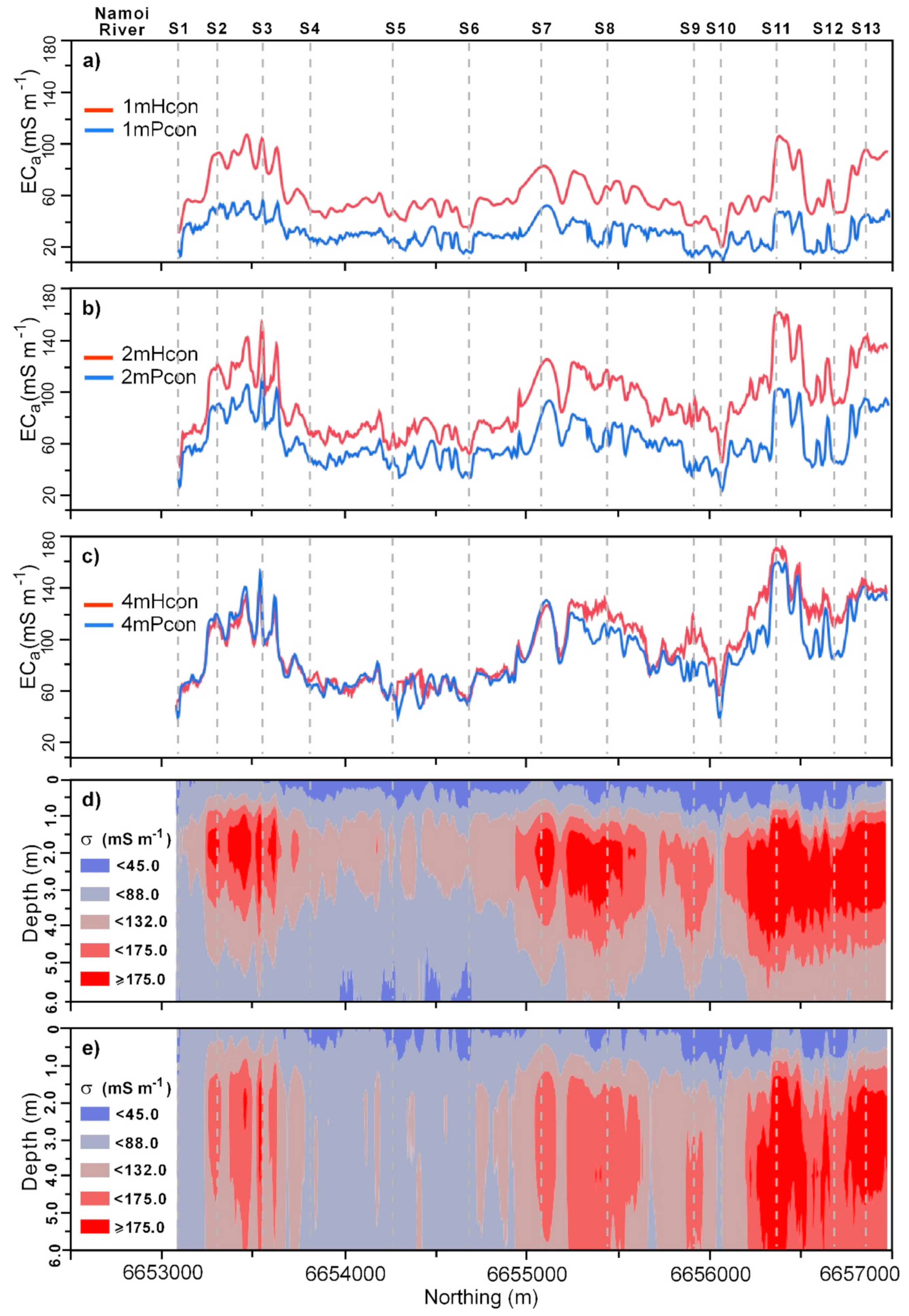
Figure 2a shows that the measured DUALEM-421 ECa of 1mHcon (100 mS m−1) and 1mPcon (50 mS m−1) were largest within 600 m of the southern (sites 2 and 3) and northern (site 11) ends. Conversely, 1mHcon (20 mS m−1) and 1mPcon (10 mS m−1) were smallest closest to Namoi River (site 1) at the southern end and near the floodway (site 10). Figure 2b shows equivalent patterns for the 2mHcon and 2mPcon. Whereas the 2mHcon was generally larger along the entire transect than either the 1mHcon or 1mPcon, the 2mPcon was equivalent to the 1mHcon. As indicated in Table 1, Figure 2c shows that the 4mHcon and 4mPcon were essentially equivalent to each other and the 2mHcon.

3.2. Preliminary Data Analysis of Soil Physical and Chemical Properties

Table 2 shows the summary statistics of measured soil physical properties at the 13 soil sampling sites. The clay ranged from small (4%) to large (77.3%), with a mean clay (44.2%) akin to a soil texture approximating a medium clay. The sand was similarly variable, with the minimum (5.9%) and maximum (92.4%) showing a larger range with a smaller mean (35.54%) than clay. The standard deviation (SD) for clay (14.1%) and sand (18.3%) were comparable.
Table 2 also shows summary statistics of the chemical properties. The ECe minimum (0.1 dS m−1) and mean (1.7 dS m−1) were non-saline (<2 dS m−1), with the maximum (3.99 dS m−1) slightly saline (2–4 dS m−1). The CEC ranged between small (1.31 cmol(+) kg−1) and large (47.7 cmol(+) kg−1), which represented good shrink-swell behaviour, and, on average, the soil had a mean CEC (24.4 cmol(+) kg−1), which indicated channel sediments that have shrink-swell behaviour. The SD of the ECe (0.9 dS m−1) and CEC (8.43 cmol(+) kg−1) were small. The pH1:5 ranged between strongly acidic (4.5) and very strongly alkaline (9.65), with a mean of moderate alkalinity (8.5). Except for the pH1:5 (−1.16), the data were not skewed.
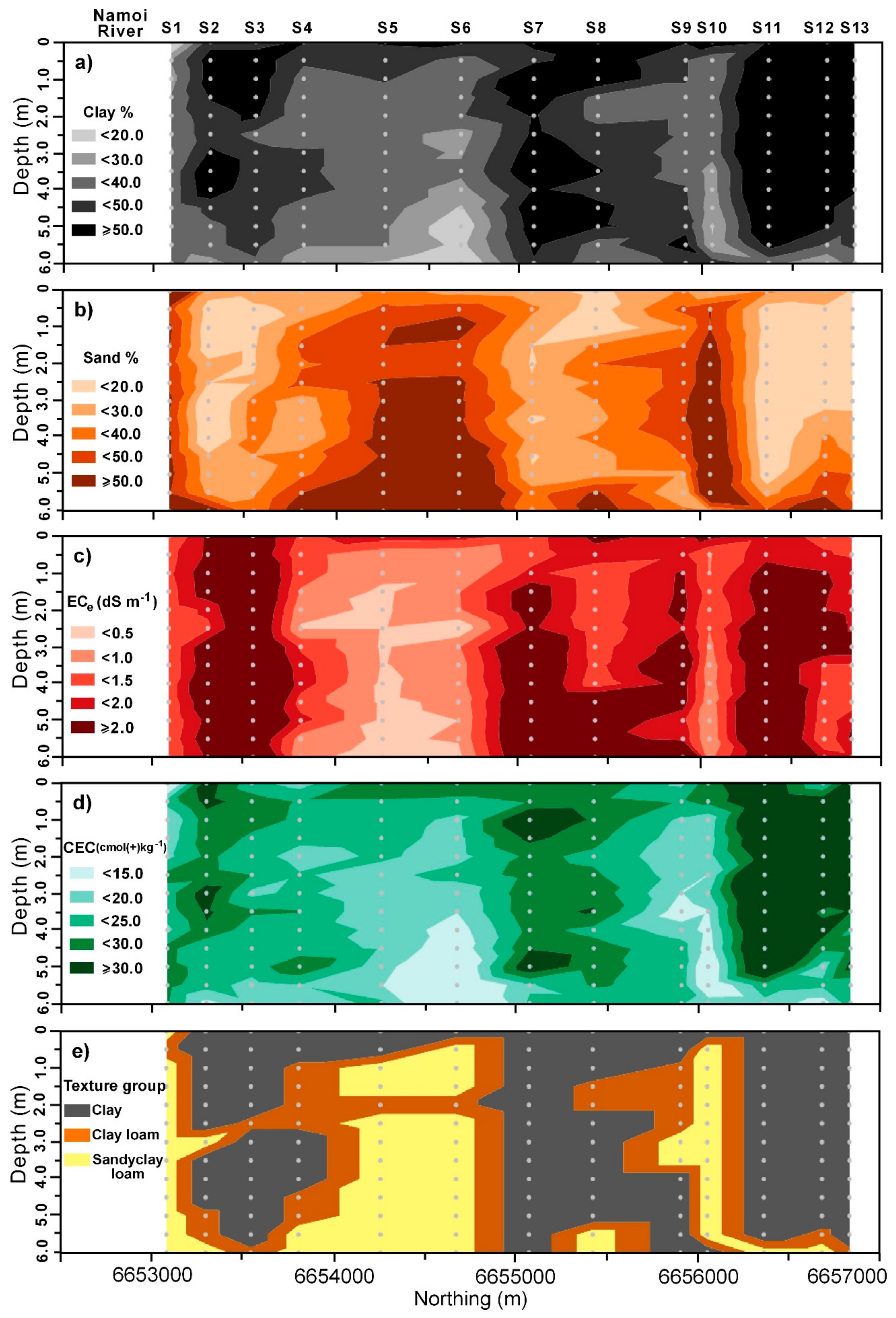
Figure 3 shows contour plots generated using JMP Software 13.2 (SAS Institute, Cary, NC, USA) of measured soil physical and chemical properties with depths and at the 13 calibration sites. Figure 3a shows clay was largest (≥50%) at the northern (11 to 13) end and in the middle of the transect (site 7) in the root (0–2 m) and vadose zone (2–6 m). This was similarly the case at the southern end (sites 2 and 3). In this regard, the 1mHcon was generally above 100 mS m−1.
Beyond 2 m, clay was variable and generally decreased, however, to intermediate-small (20–30%) clay. At the southern-most site 1, adjacent to Namoi River, clay was uniformly intermediate-small beyond the root zone, where it was small (<20%). This was also the case in the centre of the transect (sites 5 and 6) in the deeper vadose zone (4–6 m) and in the floodway (9 and 10). At these locations, the 1mHcon was smaller and generally below 40 mS m−1.
Figure 3b shows the spatial distribution of sand. For the most part, it was the inverse of clay. Specifically, at the southern end (sites 2 and 3) where clay was large, sand was small (<20%). Conversely, where clay was small, sand was large (≥50%), at the southernmost end (site 1) next to the river just to the south of the centre (sites 5 and 6) and where the channel intersects the northern part of the floodway (site 10). At these sites, large sand indicates the location of the current Namoi River, a prior stream channel and an active floodway, respectively. At these sites, we note that poorly sorted gravels were also present at various depths, particularly between 4–6 m. This indicates the presence of previous migrational channels or palaeochannels.
We also note that, at the last three sites (sites 5, 6 and 10), the location of coarser sediments was overlain in the topsoil (0–0.5 m) by intermediate clay (40–50%), which masks their presence. This was consistent with Stannard and Kelly (1977) [2], who indicated that prior stream channels in low-lying areas relative to the plain are characterised by coarse channel sediments where upper sediments were of a fine texture. Silt (data not shown) did not vary as much as clay and sand, with a narrow range (10–30%). The largest silt (20–30%) was found at most depths at the southern end (sites 2–4) but also just to the north of the centre (sites 5–7) but at deeper depths (>4 m).
Figure 3c shows distribution of the ECe, which was non-saline (i.e., <2 dS m−1). Relatively speaking, it was large (i.e., >2.0 dS m−1) in the subsoil (>2 m) and in various parts of the channel where clay was large (e.g., sites 3, 7 and 11). In the areas where sand was large, the ECe was small (<0.5 dS m−1). This suggests these areas were recharge areas and where water drains freely. Figure 3e shows the CEC was similarly distributed as a function of clay. Of note was that, at the northern end, the CEC was large (>30 cmol(+) kg−1) and most likely to have shrink-swell properties and indicate the location of vertosols. pH1:5 (data not shown) was slightly alkaline in the sandy areas (<7.5) but moderately (8–8.5) to strongly alkaline (≥8.5) in the areas with more clay of the channel.
Figure 3e shows the spatial distribution of the soil texture groups. We calculated this using the Australian textural soil classification based on the laboratory measured particle size fractions of the soil samples. Essentially, the transect was characterised by three soil texture groups but, for the most part, was predominantly clay. However, next to the river (site 1) and south of the centre (i.e., sites 4–6) and in the floodway (sites 9 and 10), the dominant texture was a sandy clay loam, with clay loams sub-dominant. What is again worth pointing out is that, in low-lying areas to the south of the centre and in the narrow floodway in the north, the veneer of finer-texture soil (clay) overlies and masks the coarser (sandy clay loam) soil associated with the prior stream formations.

3.3. Relationship between the σ and Soil Variables

The values of the σ were estimated from the inversion of all ECa measured using the DUALEM-421 instrument. By comparing various parameters (described in Section 2.4), we determined that the best correlations coefficient between the σ and soil physical and chemical properties were achieved by estimating the σ using either the CF forward model, S2 inversion algorithm and λ = 0.3 or λ = 1.8.
Figure 2 shows the EMCI from passing the DUALEM-421 ECa through EM4Soil and using the CF forward model and S2 inversion algorithm. Figure 2d shows the EMCI using a λ = 0.3, and Figure 2e shows the EMCI using λ = 1.8. For all intents and purposes, and for both EMCI, the top 1 m was uniformly small in estimates of the σ (45 mS m−1). In the areas associated with the parts of the channel with more clay, the σ increased steadily to large values (>175 mS m−1) at a depth of 1.5 m, which persisted until a depth of around 4 m, when λ = 0.3 and to 6 m, when λ = 1.8. Conversely, in the sandier parts of the channel, the σ increased to intermediate (132–175 mS m−1) values before decreasing again to small values.
Table 3 shows the best correlation coefficient (R2) between the σ and soil physical properties of clay and sand and that the chemical property of the CEC was best with the CF, S2 and λ = 0.3. All relationships, while small, were statistically significant (*** p < 0.001). The CF, S2 and λ = 1.8 produced the largest R2 (0.39) between the σ and ECe. There was also a statistically significant (*** p < 0.001) correlation between the σ and pH1:5 (0.32), with estimates of the σ from the CF, S2 and λ = 1.8. Unlike in the study by Khongnawang et al. (2019) [11], where a good R2 was achieved between the σ with clay (0.65) and the CEC (0.68) when the EM38h0 and EM38v0 ECa were inverted, this was not the case here, with either of the estimates of the σ inverted from the DUALEM-421 ECa data available.
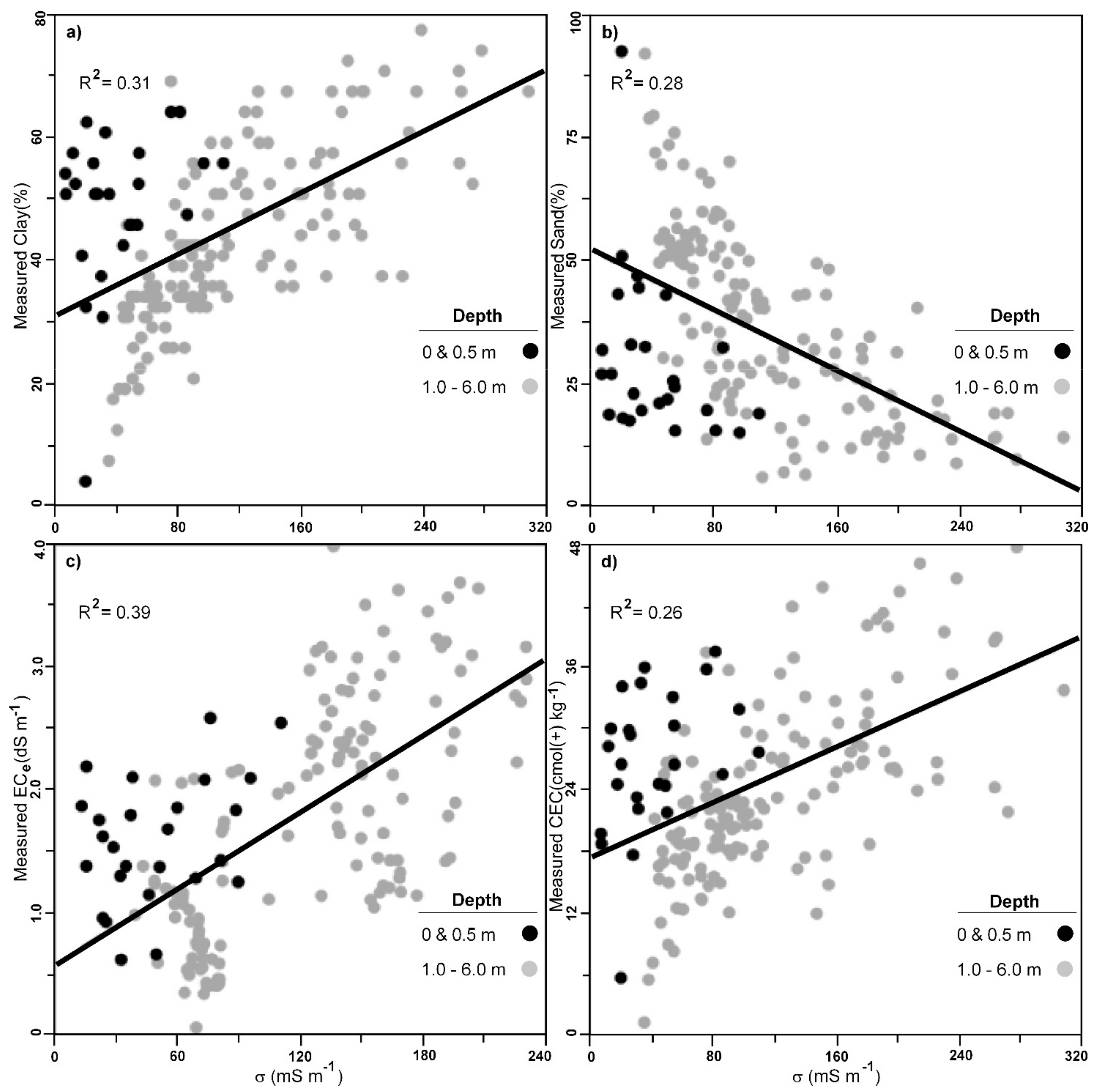
To understand the lack of correlation further, Figure 4 shows the plots of the σ, derived from the EMCI, against their respective physical and chemical properties. Figure 4a shows the plot of the σ and clay. It shows that there was linearity between the σ and clay at depths of 1–6 m. This was similarly the case with sand, ECe and CEC (Figure 4b–d, respectively). We attribute this to the σ being jointly a function of the interrelationship between clay and the CEC with ECe, whereby the salts in the subsoil accumulate as a function of aeolian and cyclical deposition over time in this semi-arid landscape.
However, this was not the case in the near surface. Specifically, samples from the surface (0 m) and subsurface (0.5 m). We attribute this to the fact that the large σ appears to be a function of the more reactive clay veneer (CEC > 25 cmol(+) kg−1) above the prior stream and floodways and along the channel, because the ECe herein was non-saline. Hence, the smaller values of the σ relative to the subsoil clay which had relatively larger amounts of salts but the same clay content and CEC.

3.4. Measured Versus Predicted Soil Properties

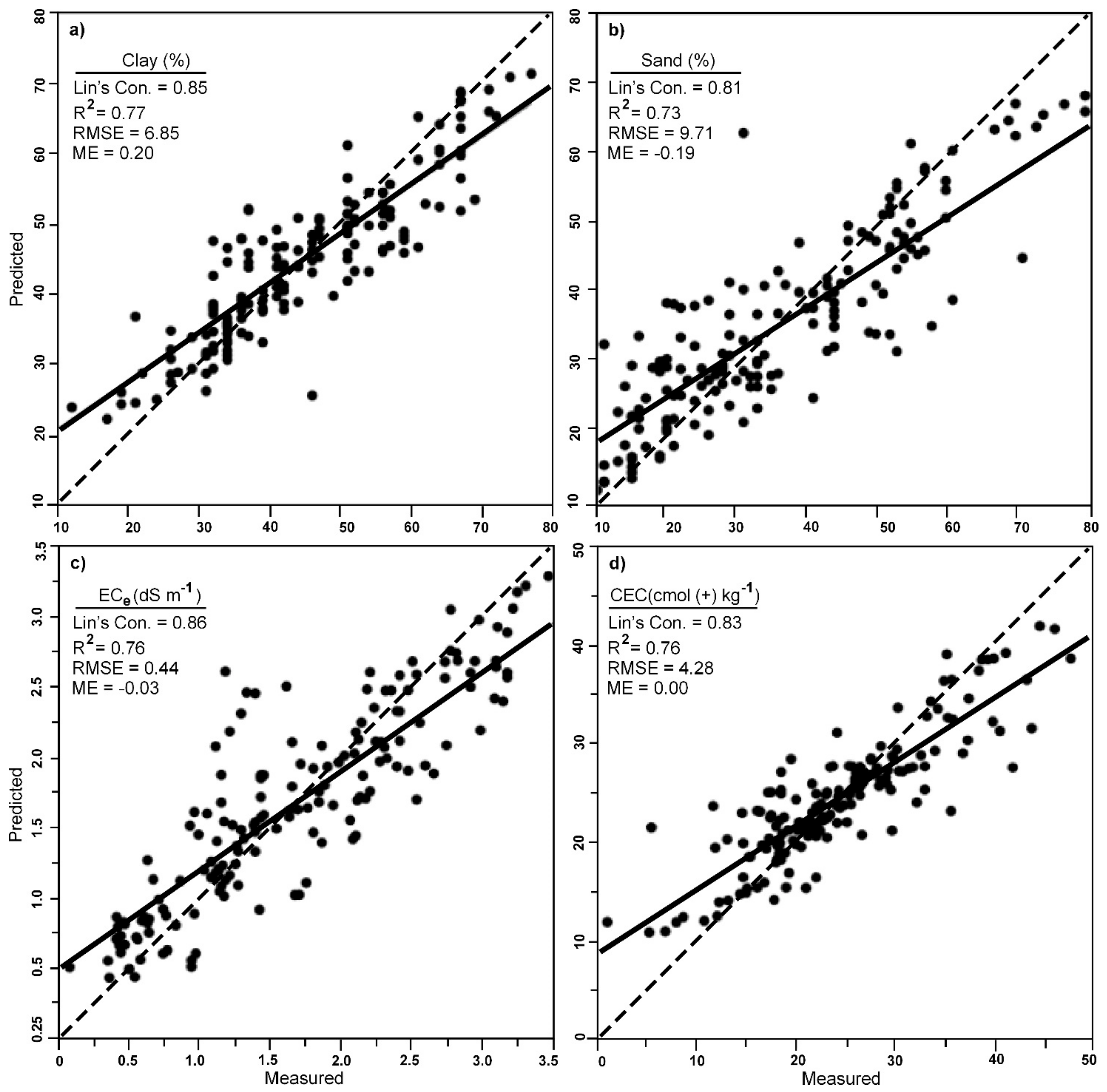
Owing to the poor linear relationships and small R2, and the inability to develop a linear or multiple linear regression model, we explored the potential to develop various SVM models between the various soil physical (i.e., clay and sand) and chemical (ECe and CEC) properties and estimates of the σ. We also considered depth in each SVM model. Figure 5 shows the leave-one-site-out cross-validation between measured and predicted soil properties using the SVM models.
Figure 5a shows the predicted clay was in good agreement (Lin’s = 0.85) with the measured clay, with the prediction precision (RMSE = 6.85) and bias (ME = 0.20) both being small and close to zero, respectively. Given the RMSE was less than half the SD for the measured clay (7.07%), we can consider these predictions of clay overall as satisfactory [30]. They were also unbiased (ME = 0.20). Figure 5b shows a comparable result achieved for sand, and while the concordance (Lin’s = 0.81) was smaller than clay, the predicted sand was still in good agreement. Prediction precision (RMSE = 9.71%) was also larger than clay; nevertheless, the prediction is still considered satisfactory, because the predicted sand was close to half the SD for the measured sand (9.15%).
With respect to the chemical properties of interest, similar conclusions can be drawn regarding their prediction using the leave-one-site-out cross-validation results. In terms of salinity, Figure 5c shows for the ECe there was good concordance (Lin’s = 0.86). Again, not only were the predictions precise (RMSE = 0.44 dS m−1) and unbiased (ME = −0.03 dS m−1), the precision was satisfactory given they were less than half the SD of the measured ECe (0.45 dS m−1). Figure 5d shows that, for the CEC, equivalent results were achieved with predictions showing good concordance (Lin’s = 0.83), with precise (4.28 cmol(+) kg−1) and unbiased (0) predictions.

3.5. Mapping Soil Properties with Depth and Along the Channel

To understand the results from a pedological, geomorphological, soil and water use and management standpoint, we plotted the predicted physical and chemical properties beneath the channel. We did this by applying the SVM using the EMCIs generated from the various ECa data, using the CF and S2, with maximum iteration of 10 and λ = 0.3 (Figure 2d) for clay and sand and the CEC and λ = 1.8 for the ECe (Figure 2e).
Figure 6a shows that, for the most part, the pattern of predicted clay was consistent with measured clay (Figure 3a). What was evident was the uniform nature of the predicted clay (40–50%) in the surface (0 m) and subsurface (0.5 m) along most of the supply channel. We note that the clay was slightly underpredicted in the central-north part of the channel, however, where the heavy clay plain was evident (sites 7–10). Nevertheless, the heavy clay (>50%) of the plain in the northern part (sites 11–13) was well-predicted. So too was the veneer of intermediate-large (40–50%) clay, which overlied the prior stream channel in the centre and to the south (sites 4–6).
The location of a paleochannel, which commonly underlies the clay plain herein at a depth of around 5–6 m where the clay (<30%) was intermediate-small, was also well-resolved. These indicate places where previous migrational channel deposits (palaeochannels), characterised by coarse sands and gravels (Stannard and Kelly, 1968), shown in Figure 1c can be found. Figure 6b shows this more succinctly due to the large sand (>50%) evident (4.5–6 m) in the area of the prior stream channel just south of the centre (sites 4–6) and also the area of the floodway in the northern third of the channel (near sites 9 and 10).
Figure 6c shows that the predicted ECe was consistent with the slightly saline (2–4 dS m−1) nature of the vertosols, which characterise the clay plain. The non-saline (<2 dS m−1) and highly leached nature of the prior stream formations and the coarser sandy clay loam textures of the dermosols were also well-discerned. Figure 6d helps further explain these results, as it shows where the clay was most reactive and reinforces the notion that the clays with larger CEC (30 cmol(+) kg−1) will be more reactive in terms of their shrink and swell and most likely help form a seal in the channel and hold the water sufficiently to enable its conveyance most efficiently along the northern section of the channel.
Conversely, the less reactive parts of the channel (<20 cmol(+) kg−1) indicates where the shrink-swell behaviour would be poor and where losses can be expected. This aligns well with the sandy clay loam soil textures, which characterise the prior stream channels and floodway (see Figure 6e). This idea is generally supported by the generally non-saline nature of the soil and vadose zone, thereby indicating where recharge occurs along the channel. We note that the prior stream channel clay content was less than 40%, and this was consistent with where research in the nearby lower Gwydir Valley showed that these clay contents were susceptible to excess deep drainage at the field [34] and district scale [4].
The results described herein have implications for the remaining lower Namoi Valley, where many other supply channels remain unsurveyed. This is because a similar approach can be used by an increasingly large number of consultants who commonly conduct EM surveys using the more popular Geonics EM38 or smaller versions of the DUALEM range of instruments, including DUALEM-1. In this regard, further research could be conducted to see if equivalent calibrations can be developed to predict the physical and chemical properties described herein but only using a smaller number of ECa values. The transect studied herein could act as a calibration location. We also recommend that a similar approach can be used to develop equivalent calibrations to enable predictions in other cotton growing-areas of Australia.
Moreover, the results described herein indicate that, in a section of the supply channel which extends some 300 m across a prior stream channel, future work needs to be undertaken to determine engineering solutions to seal the areas where the clay was predicted to be small (<40%) and were indicative of where more permeable dermosols were likely to exist.

4. Conclusions

Using a DUALEM-421, we have shown where soil samples sites can be located to characterise the soil types beneath a supply channel based on the measured ECa. Using EM4Soil inversion software, we also demonstrated how estimates of the σ can be derived from an inversion of ECa from a DUALEM-421. Moreover, we showed how these estimates of the σ were correlated with the soil physical properties of clay and sand and chemical properties of the CEC when they were estimated using the CF, S2 and λ = 0.3 and the ECe using the CF, S2 and λ = 1.8. While these relationships were statistically significant (*** p < 0.001), the correlations were not strong (R2 < 0.4). We attribute these poor correlations to the fact that the DUALEM-421 ECa response was a function of four separate soil properties (i.e., clay content and mineralogy, salinity and moisture), and the relationship of each of these and the σ was nonlinear. This was particularly the case for the topsoil (0 and 0.5 m) samples.
Given we also have a limited number of soil cores, we found that, by using an SVM, we could establish a model between the σ and clay and ECe and CEC using the same EMCI. To validate the SVM, we used a leave-one-site-out cross-validation, which produced a good 1:1 agreement with clay (0.85), sand (0.81), ECe (0.86) and CEC (0.83). Our interpretation of the predicted ECe suggests the approach can identify recharge (non-saline) areas. These aligned with where the clay (<40%) was relatively small and in areas associated with prior stream channels that were typically underlain by migrational palaeochannels.
We attribute our success to the ability of the SVM to perform well on datasets that are nonlinear, sparse and are highly dimensional. The results have practical implications for the farmer and where future work should be focused—in particular, along a 300-m section of the supply channel where a prior stream channel was masked by a thin veneer of clay alluvium. Herein, future work needs to be undertaken to determine a suitable engineering solution to seal areas like this, where the clay was predicted to be too small (<40%) and susceptible to deep drainage.
We suggest that, with this calibration, the approach can be used to predict the soil physical and chemical properties within the supply channels across the rest of the valley. Future research should also explore whether similar calibrations can be developed to enable characterisations in other cotton-growing areas of Australia.

Author Contributions

Conceptualisation and investigation, E.Z. and J.T.; formal analysis, data curation, visualisation and resources, E.Z.; writing—original draft preparation, E.Z. and J.T.; software and validation, E.Z., N.L., T.K. and M.F. and supervision, J.T. All authors have read and agreed to the published version of the manuscript.

Funding

This research was financially supported by the Australian Federal Governments Cotton Research and Development Corporation (CRDC) through a research project entitled “Where does the water go?” The first author also acknowledges an Australian Federal Government Research Training Program Scholarship and a top-up scholarship from the CRDC.

Acknowledgments

We acknowledge unrestricted access from the farmer to allow us to undertake the study on their property.

Conflicts of Interest

The authors declare no conflicts of interest.

References

  1. Triantafilis, J.; Ward, W.; McBratney, A. Land suitability assessment in the Namoi Valley of Australia, using a continuous model. Soil Res. 2001, 39, 273–289. [Google Scholar] [CrossRef]
  2. Stannard, M.; Kelly, I.D.; New South Wales Water Resources Commission. The Irrigation Potential of the Lower Namoi Valley; Water Resources Commission: Sydney, NSW, Australia, 1977. [Google Scholar]
  3. Triantafilis, J.; Ribeiro, J.; Page, D.; Santos, F.M. Inferring the location of preferential flow paths of a leachate plume by using a DUALEM-421 and a Quasi-Three-Dimensional inversion model. Vadose Zone J. 2013, 12. [Google Scholar] [CrossRef]
  4. Triantafilis, J.; Odeh, I.; Jarman, A.; Short, M.; Kokkoris, E. Estimating and mapping deep drainage risk at the district level in the lower Gwydir and Macquarie valleys, Australia. Aust. J. Exp. Agric. 2004, 44, 893–912. [Google Scholar] [CrossRef]
  5. Woodforth, A.; Triantafilis, J.; Cupitt, J.; Malik, R.; Subasinghe, R.; Ahmed, M.; Huckel, A.; Geering, H. Mapping estimated deep drainage in the lower Namoi Valley using a chloride mass balance model and EM34 data. Geophysics 2012, 77, WB245–WB256. [Google Scholar] [CrossRef]
  6. Muzzamal, M.; Huang, J.; Nielson, R.; Sefton, M.; Triantafilis, J. Mapping soil particle-size fractions using additive log-ratio (ALR) and isometric log-ratio (ILR) transformations and proximally sensed ancillary data. Clays Clay Miner. 2018, 66, 9–27. [Google Scholar] [CrossRef]
  7. Nagra, G.; Burkett, D.; Huang, J.; Ward, C.; Triantafilis, J. Field level digital mapping of soil mineralogy using proximal and remote-Sensed data. Soil Use Manag. 2017, 33, 425–436. [Google Scholar] [CrossRef]
  8. Li, N.; Zare, E.; Huang, J.; Triantafilis, J. Mapping soil cation-Exchange capacity using Bayesian modeling and proximal sensors at the field scale. Soil Sci. Soc. Am. J. 2018, 82, 1203–1216. [Google Scholar] [CrossRef]
  9. Zare, E.; Huang, J.; Santos, F.; Triantafilis, J. Mapping salinity in three dimensions using a DUALEM-421 and electromagnetic inversion software. Soil Sci. Soc. Am. J. 2015, 79, 1729–1740. [Google Scholar] [CrossRef]
  10. Zhao, X.; Wang, J.; Zhao, D.; Li, N.; Zare, E.; Triantafilis, J. Digital regolith mapping of clay across the Ashley irrigation area using electromagnetic induction data and inversion modelling. Geoderma 2019, 346, 18–29. [Google Scholar] [CrossRef]
  11. Khongnawang, T.; Zare, E.; Zhao, D.; Srihabun, P.; Triantafilis, J. Three-Dimensional Mapping of Clay and Cation Exchange Capacity of Sandy and Infertile Soil Using EM38 and Inversion Software. Sensors 2019, 19, 3936. [Google Scholar] [CrossRef] [Green Version]
  12. Isbell, R. The Australian Soil Classification; CSIRO Publishing: Clayton, VIC, Australia, 2016. [Google Scholar]
  13. Pietsch, T.J. Fluvial geomorphology and late quaternary geochronology of the Gwydir fan-Plain. Ph.D. Thesis, University of Wollongong, Wollongong, NSW, Australia, 2006. [Google Scholar]
  14. Stannard, M.; Kelly, I.D.; New South Wales Water Conservation and Irrigation Commission. The Irrigation Potential of the Lower Gwydir Valley; Water Conservation and Irrigation Commission: Sydney, NSW, Australia, 1968. [Google Scholar]
  15. Dualem Inc. DUALEM-421S user’s Manual; Dualem Inc.: Milton, ON, Canada, 2008. [Google Scholar]
  16. Beretta, A.N.; Silbermann, A.V.; Paladino, L.; Torres, D.; Bassahun, D.; Musselli, R.; García-Lamohte, A. Soil texture analyses using a hydrometer: Modification of the Bouyoucos method. Cienc. Investig. Agrar. 2014, 41, 263–271. [Google Scholar] [CrossRef] [Green Version]
  17. Moody, P.W.; Phan, T.C. Soil Constraints and Management Package (SCAMP): Guidelines for Sustainable Management of Tropical Upland Soils; Australian Centre for International Agricultural Research (ACIAR): Canberra, ACT, Australia, 2008.
  18. Slavich, P.; Petterson, G. Estimating the electrical conductivity of saturated paste extracts from 1: 5 soil, water suspensions and texture. Soil Res. 1993, 31, 73–81. [Google Scholar] [CrossRef]
  19. Tucker, B. Laboratory Procedures for Cation Exchange Measurements on Soils; Commonwealth Scientific; Industrial Research Organization: Canberra, ACT, Australia, 1974.
  20. EM4Soil V.304; EMTOMO: Lisbon, Portugal, 2018.
  21. Santos, F.; Triantafilis, J.; Bruzgulis, K.; Roe, J. Inversion of multiconfiguration electromagnetic (DUALEM-421) profiling data using a one-dimensional laterally constrained algorithm. Vadose Zone J. 2010, 9, 117–125. [Google Scholar] [CrossRef]
  22. Monteiro Santos, F.A.; Triantafilis, J.; Taylor, R.S.; Holladay, S.; Bruzgulis, K.E. Inversion of conductivity profiles from EM using full solution and a 1-D laterally constrained algorithm. J. Environ. Eng. Geophys. 2010, 15, 163–174. [Google Scholar] [CrossRef]
  23. Auken, E.; Foged, N.; Sørensen, K.I. Model recognition by 1-D laterally constrained inversion of resistivity data. In Proceedings of the 8th EEGS-ES Meeting, Aveiro, Portugal, 8–12 September 2002; European Association of Geoscientists & Engineers: Houten, The Nethelrands, 2002; p. 36. [Google Scholar]
  24. Gunn, S.R. Support vector machines for classification and regression. ISIS Tech. Rep. 1998, 14, 5–16. [Google Scholar]
  25. Williams, G. Data Mining with Rattle and R: The Art of Excavating Data for Knowledge Discovery; Springer Science & Business Media: Berlin/Heidelberg, Germany, 2011. [Google Scholar]
  26. Platt, J. Probabilistic outputs for support vector machines and comparisons to regularized likelihood methods. Adv. Large Margin Classif. 1999, 10, 61–74. [Google Scholar]
  27. Smola, A.J.; Schölkopf, B. A tutorial on support vector regression. Stat. Comput. 2004, 14, 199–222. [Google Scholar] [CrossRef] [Green Version]
  28. Meyer, D.; Dimitriadou, E.; Hornik, K.; Weingessel, A.; Leisch, F.; Chang, C.; Lin, C. e1071: Misc functions of the Department of Statistics (e1071), TU Wien. R Package Version 2014. [Google Scholar]
  29. Barnston, A.G. Correspondence among the correlation, RMSE, and Heidke forecast verification measures; refinement of the Heidke score. Weather Forecast. 1992, 7, 699–709. [Google Scholar] [CrossRef] [Green Version]
  30. Singh, J.; Knapp, H.V.; Arnold, J.; Demissie, M. Hydrological modeling of the Iroquois river watershed using HSPF and SWAT 1. J. Am. Water Resour. Assoc. 2005, 41, 343–360. [Google Scholar] [CrossRef]
  31. Walther, B.A.; Moore, J.L. The concepts of bias, precision and accuracy, and their use in testing the performance of species richness estimators, with a literature review of estimator performance. Ecography 2005, 28, 815–829. [Google Scholar] [CrossRef]
  32. Lin, L.I.-K. A concordance correlation coefficient to evaluate reproducibility. Biometrics 1989, 45, 255–268. [Google Scholar] [CrossRef] [PubMed]
  33. McBride, R.B.; McBride, G.; McBride, G.B.; MCBRIDE, G.B.; McBride, J.B.; McBride, B. A Proposal for Strength-of-Agreement Criteria for Lins Concordance Correlation Coefficient; NIWA client report: HAM2005-062; NIWA: Auckland, New Zealand, 2005; Available online: https://www.medcalc.org/download/pdf/McBride2005.pdf.
  34. Triantafilis, J.; Huckel, A.; Odeh, I. Field-Scale assessment of deep drainage risk. Irrig. Sci. 2003, 21, 183–192. [Google Scholar] [CrossRef]
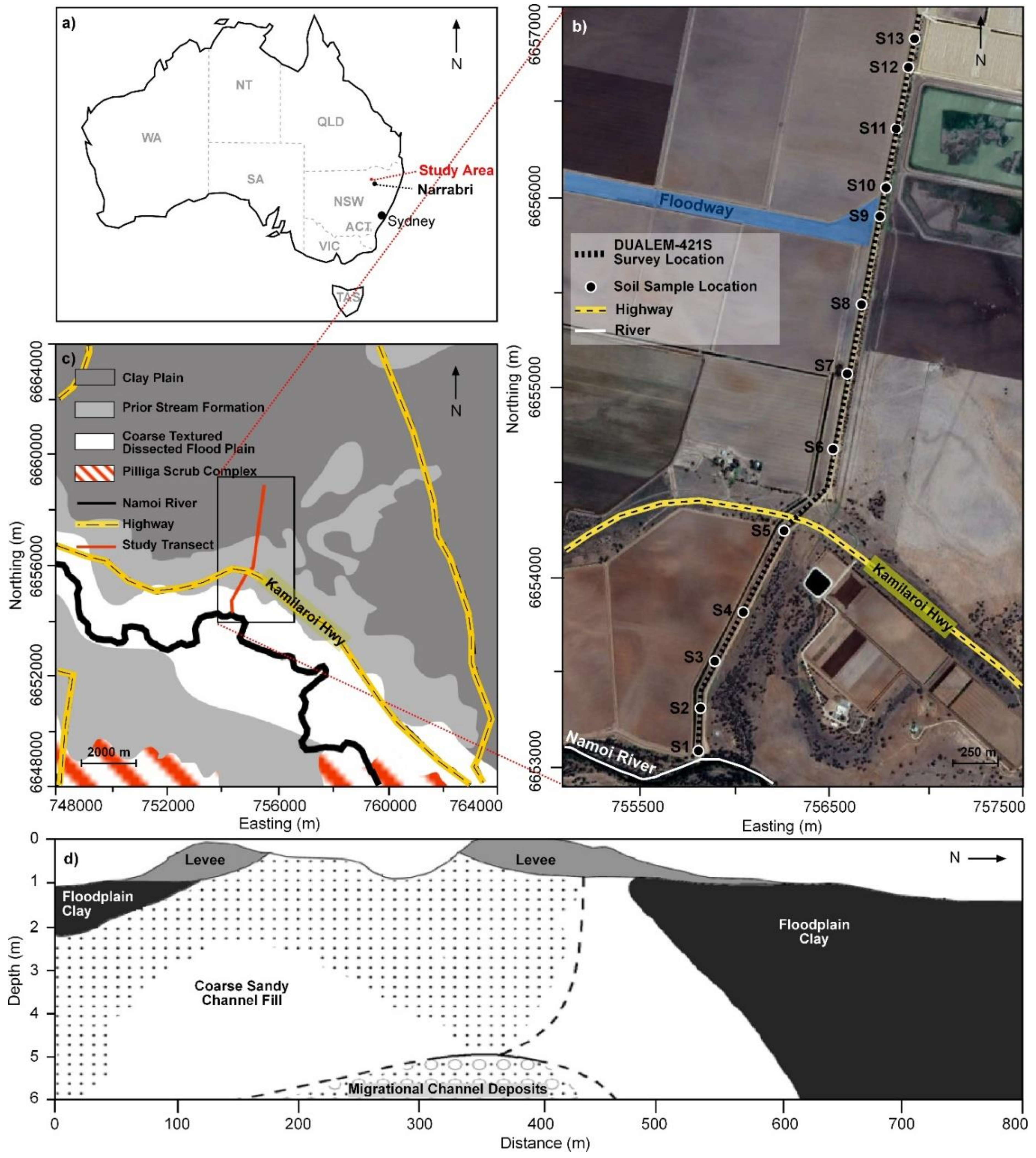
Figure 1. (a) Location of the study area, (b) air photo (Google Earth) of the study supply channel either side of the Kamilaroi Highway and a local floodway with a location of soil apparent electrical conductivity (ECa—mS m−1) survey transect and soil sample sites (13), (c) physiography of the lower Namoi valley (after Stannard and Kelly, 1968 [14]) and (d) general shallow stratigraphy near prior stream channels nearby Gwydir Valley (after Pietsch, 2006 [13]).
Soilsystems 04 00025 g001
Figure 2. Measured the soil apparent electrical conductivity (ECa—mS m−1) from DUALEM-421 in the horizontal (Hcon) and perpendicular (Pcon) coplanar arrays, including (a) 1mHcon and 1mPcon, (b) 2mHcon and 2mPcon and (c) 4mHcon and 4mPcon with electromagnetic conductivity images (EMCI) of estimates of the true electrical conductivity (σ—mS m−1) considering the inversion of all DUALEM-421 ECa and using the cumulative function forward model (CF), S2 inversion algorithm and λ = (d) 0.3 and (e) 1.8.
Soilsystems 04 00025 g002
Figure 3. Contour plots of the spatial distribution of soil physical and chemical properties at soil sampling sites (13) along the channel, including (a) clay (%), (b) sand (%), (c) electrical conductivity of a saturated soil paste extract (ECe—dS m−1) estimated from 1-part soil, 5-part water solution, (d) cation exchange capacity (CEC—cmol(+) kg−1) and (e) the contour plots of soil textures at the soil sampling sites (×13).
Soilsystems 04 00025 g003
Figure 4. Plots of estimates of the true electrical conductivity (σ—mS m−1) versus the predicted (a) clay (%), (b) sand (%), (c) electrical conductivity of a saturated soil paste extract (ECe—dS m−1) and (d) cation exchange capacity (CEC—cmol(+) kg−1).
Soilsystems 04 00025 g004
Figure 5. Leave-one-site-out cross-validation plots of measured versus predicted (a) clay (%), (b) sand (%,) (c) electrical conductivity of a saturated soil paste extract (ECe—dS m−1) and (d) cation exchange capacity (CEC—cmol(+) kg−1).
Soilsystems 04 00025 g005
Figure 6. The spatial distribution of the predicted (a) clay (%), (b) sand (%), (c) electrical conductivity of a saturated soil paste extract (ECe—dS m−1), (d) cation exchange capacity (CEC—cmol(+) kg−1) generated using a support vector machine (SVM) model and from estimates of the true electrical conductivity (σ—mS m−1) of the DUALEM-421 along with depth and (e) the spatial distribution with the depths of the soil texture groups calculated using the Australian textural soil classification-based predicted clay and sand.
Soilsystems 04 00025 g006
Table 1. Summary statistics of apparent electrical conductivity (ECa—mS m−1) measured by a DUALEM-421 for the entire survey transect and at the 13 calibration sites. Hcon—horizontal coplanar array and Pcon—perpendicular coplanar array.
DUALEM-421NMinMeanMaxMedianCV (%)SDSkewness
Survey Data
1mHcon295921621075728180.7
1mPcon29591132573131100.4
2mHcon295944911618528260.6
2mPcon295924611115628170.7
4mHcon295948951729030290.5
4mPcon295940891618330260.6
Calibration data
1mHcon1323631064947290.3
1mPcon131632562650160.4
2mHcon1348971619241400.3
2mPcon1330631104747290.4
4mHcon135310317111538400.1
4mPcon1343951618944420.3
Table 2. Summary statistics of measured soil properties. Note: soil salinity of the saturated soil paste extract (ECe—dS m−1) estimated from the measured electrical conductivity from a 1-part soil to 5-parts water extract (EC1:5), cation exchange capacity (CEC—cmol(+) kg−1) and pH of a 1-part soil to 5-parts water extract (pH1:5).
Soil PropertiesNMinMeanMaxMedianCV (%)SDSkewness
Clay (%)1694.0044.1877.3342.3331.9914.130.02
Silt (%)1690.7320.2941.2319.7738.777.880.19
Sand (%)1695.9035.5492.4031.8751.5118.310.63
ECe (dS m−1)1690.081.733.991.6452.000.900.36
CEC (cmol(+)kg−1)1691.3124.4147.6723.3234.538.430.33
pH1:51694.478.309.658.49.150.76−1.16
Table 3. Coefficient of determination (R2) between selected estimates of true electrical conductivity (σ—mS m−1) and various soil properties. Note: soil salinity of saturated soil paste extract (ECe—dS m−1) estimated from measured electrical conductivity from a 1-part soil to 5-parts water extract (EC1:5), cation exchange capacity (CEC—cmol(+) kg−1) and pH of a 1-part soil to 5-parts water extract (pH1:5). CF—cumulative function, p—statistical significance (p-value).
Soil PropertiesR2
0.3 S2 CF1.8 S2 CF
Clay (%)0.31 ***0.25 ***
Silt (%)0.05 **0.06 **
Sand (%)0.28 ***0.23 ***
ECe (dS m−1)0.22 ***0.39 ***
CEC (cmol(+)kg−1)0.26 ***0.17 ***
pH1:50.18 ***0.32 ***
* p < 0.05, ** p < 0.01 and *** p < 0.001