1. Introduction
The superradiance of Smith-Purcell (SP) emissions was first observed in 1998 at wavelengths of 300–900 μm using an electron beam propagating just above a grating at energy of 20–40 keV [
1]. The superradiant SP radiation was theoretically studied by Andrews and Brau [
2,
3]. They proposed an SP free-electron laser (FEL) theory in which evanescent waves induced on the grating surface contribute to the formation of electron microbunching spaced at the evanescent wavelength. The SP radiation from the electron microbunching can be coherently enhanced at fundamental or higher harmonics of the evanescent wavelength. However, the fundamental wavelength of the evanescent wave is longer than the SP radiation wavelength, and coherent SP radiation occurs only at the higher harmonics. The evanescent wavelength was experimentally verified to be longer than that of the SP radiation, and coherent SP radiation at the second and third harmonics of the evanescent waves was observed [
4,
5]. These theoretical and experimental studies promise a compact, high-power terahertz (THz) light source based on the SP FEL technique.
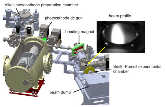
We have developed a photocathode dc gun at the National Institutes for Quantum Radiological Science and Technology (QST). The gun was originally developed as a dc gun equipped with a GaAs photocathode for future light sources and was used for studying magnetic emittance suppression [
6]. The gun system consists of a SF
6 tank with a Cockcroft-Walton high-voltage power supply (HVPS), a high-voltage chamber, a GaAs preparation chamber, a solenoid, a lightbox for driving the laser injection and a diagnostic beamline. We added an alkali antimonide photocathode preparation system to the gun system because alkali antimonide has a longer lifetime than GaAs and is more appropriate for high-current beam applications [
7]. The 1/e lifetime of a GaAs photocathode during 52 mA beam generation is a few hours, while that of a CsK
2Sb photocathode during 60 mA beam generation is 30 h [
8]. Electron beam generation with currents of up to 75 mA was demonstrated at the Cornell photoinjector with an alkali antimonide photocathode, and the charge lifetime was measured as greater than 15 kC [
9]. In addition, a low-emittance electron beam for high-repetition-rate X-ray FEL has been demonstrated with an alkali antimonide photocathode [
10].
In this paper, we report the status of our photocathode dc gun development and preparation for SP FEL experiments. In
Section 2, the parameters for the SP FEL experiment are shown. In
Section 3, an alkali antimonide photocathode preparation system and the first fabrication results for our Cs
3Sb photocathode are presented. The quantum efficiency (QE) reached 5% and the 1/e dark lifetime of the photocathode was longer than a year. In
Section 4, the high-voltage performance of our dc gun system is described. The cathode electrode of the gun was replaced to reduce the surface electric field. We applied a voltage of 210 kV with the cathode electrode in place for more than 8 h with no discharge. In
Section 5, the beam generation results are presented. We prepared a downstream beamline for high-current beam operation and generated an electron beam from the Cs
3Sb photocathode with a current of up to 4.3 mA at 150 kV. Finally, the conclusion is given in
Section 6.
2. Preparation for SP FEL Experiment
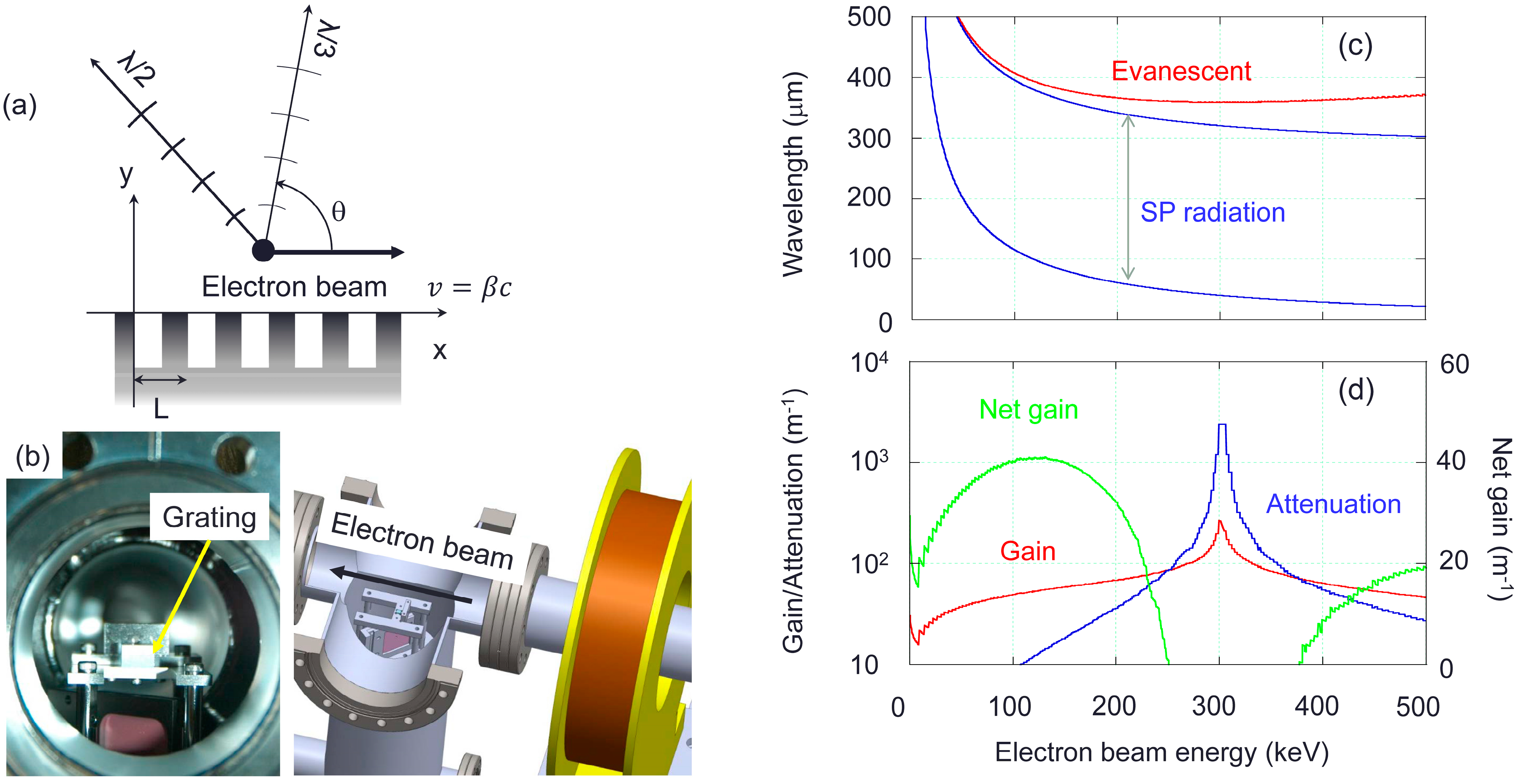
Experimental parameters for our SP FEL at THz wavelengths are listed in
Table 1. The temporal structure of the electron beam depends on the temporal profile of the drive laser pulse for the photocathode dc gun. In the present study, a dc electron beam was generated from the gun because a continuous-wave laser was used as the drive laser. When an electron beam with velocity
cβ is propagating above a grating with period
L (
Figure 1a), the SP radiation wavelength at angle
θ is given by
Figure 1b shows our grating and the beam profile monitor for the SP FEL experiment. The evanescent wavelength,
λ, derived from the dispersion relation described in Reference [
2] is shown by the red curve as a function of electron gun voltage in
Figure 1c. The SP wavelength changes as a function of the emission angle, as shown in Equation (1), and the wavelength region is between the two blue curves. The SP radiation at wavelengths corresponding to the second or higher harmonics of evanescent wavelength
λ is enhanced coherently, as shown in
Figure 1a. The gain and attenuation loss of the evanescent waves due to magnetic resistance are calculated following Reference [
3] and are shown in
Figure 1d. We assume a dc electron beam current of 50 mA, because the maximum average beam current is limited to 50 mA due to the HVPS capacity of our dc gun. A beam diameter of 560 μm is assumed, as described in the following. An important advantage of using a photocathode electron gun for the SP-FEL experiments is its low emittance. The normalized thermal emittance per root mean square (rms) laser spot size is measured to be 0.56 ± 0.03 mm-mrad/mm (rms) [
11]. Because the emittance growth due to the space charge effect is negligibly small for low-current beams such as 50 mA, the normalized emittance is
εny = 0.1 mm-mrad when the laser spot size is 0.2 mm rms. The Lorentz factor,
γ, multiplied by normalized electron beam velocity
β is
βγ ≈ 1 for a 200 keV electron beam, and the unnormalized emittance is Σ
y ≈ Σ
ny for a 200 keV beam. If we assume beta function
βy = 0.2 m at the beam waist, the rms beam waist size is
σy = 0.14 mm, which corresponds to diameter of 560 μm, under these electron beam conditions. The beam size listed in
Table 1 can thus be satisfied. The distance between the grating surface and electron beam center is assumed to be 280 μm because the electron density just above the grating is assumed to be the same as that of the electron beam for deriving the SP FEL gain by Andrews and Brau [
2,
3].
The SP FEL occurs at electron beam energies where the gain is greater than the attenuation loss under the condition that the group velocity of the evanescent wave is negative for the feedback operation of the SP FEL. Thus, the electron beam energy should be lower than 250 kV for our parameters. The grating whose parameters are shown in
Table 1 is mounted on a holder with a linear motion and is installed in the vacuum chamber. The holder has a screen to monitor the beam size and position at the grating. The SP FEL is outcoupled through a quartz window transparent to THz wavelengths and is measured with a THz detector (WR1.0ZBD, Virginia Diodes, Charlottesville, VA, USA) for 0.75–1.1 THz equipped with a horn antenna and a mesh filter with 9.8% bandwidth and a central wavelength of 1.022 THz.
A numerical simulation of the SP FEL showed that an external magnetic field along the electron beam propagation direction is required on the grating to prevent blow-up of the electron microbunching due to space charge effects [
12]. This is necessary for stable operation of the SP FEL. Although such an external magnetic field is not used in the experiments in References [
1,
4], an external magnetic field of 0.3 to 0.5 T is used for experiments at the Center for Scientific and Technical Study of Aquitaine (Cesta) in France [
5,
13,
14]. We need to rearrange our experimental setup to add a permanent solenoid magnet similar to that used for laser-accelerated electron beams [
15] near the grating.
3. Preparation System for the Alkali Antimonide Photocathode
We have developed an alkali antimonide photocathode preparation system following References [
16,
17]. A 0.5-mm-thick Si wafer is used as a substrate. The wafer is attached to a Mo puck with an In seal. The puck is the same as that used for the GaAs photocathode for the 500 kV photoemission dc gun in the compact energy recovery linac (cERL) at the High Energy Accelerator Research Organization (KEK) [
18,
19].
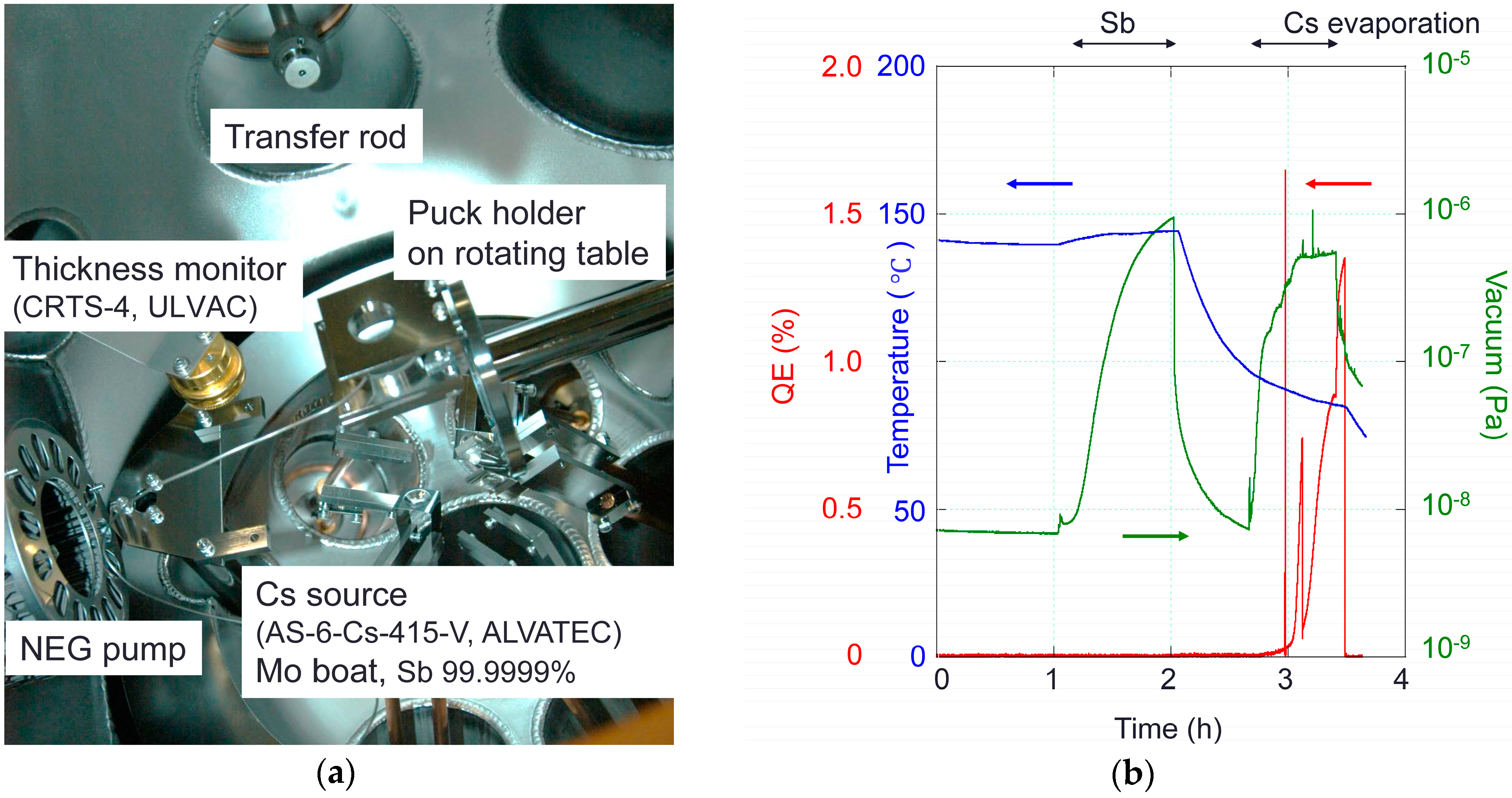
Figure 2 shows a photograph of the inside of the alkali antimonide photocathode preparation chamber. The puck is mounted in a puck holder on a rotating table for photocathode fabrication. The activated photocathode is transferred to the gun high-voltage chamber for beam generation (
Figure 2). A linearly moving tungsten heater is used for heat cleaning the wafer and heating the wafer to temperatures appropriate for evaporating Sb and alkali metals. The temperature is monitored with a thermocouple connected to the puck holder.
We fabricated the Cs3Sb photocathode first because it is the simplest alkali antimonide photocathode. A 99.9999% Sb bead (SB-020100, NILACO, Tokyo, Japan) was placed on a Mo boat. The boat was heated to evaporate the Sb. A Cs source (AS-6-Cs-415-V, ALVATEC, Althofen, Austria) was placed 3 cm from the substrate surface. A thickness monitor (CRTS-4U, ULVAC, Chigasaki, Japan) was used to calibrate thicknesses of both Sb and Cs. The photocathode preparation system was baked for 20 h at 170 °C with a 0.3 m3/s turbo molecular pump. A 1.3 m3/s NEG pump (CapaciTorr-B 1300-2, SAES Getters, Milan, Italy) was activated after baking. A 0.05 m3/s ion pump (PST-050AU, ULVAC, Chigasaki, Japan) was used to pump noble gases and methane. A vacuum pressure of 5 × 10⁻⁹ Pa was obtained after NEG activation. The wafer was heat cleaned at 550 °C for 2 h to remove oxides from the surface.
The photocathode was fabricated 2 days later. The puck holder was heated and held at the monitor temperature of 140 °C. The Sb was evaporated for a duration corresponding to a 40-nm-thick layer of Sb. The relationship between the evaporation time and thickness was calibrated in a separate experiment with a thickness monitor. After the evaporation of Sb, the monitor temperature was decreased to 90 °C for the Cs evaporation. The wafer was irradiated with a 532 nm laser with maximum power of 5 mW and the photocurrent was measured with a Faraday cup in front of the puck holder. Once the photocurrent was detected, the heater power for Cs evaporation was increased until optimum conditions were reached and the laser power was decreased with a neutral density filter. We stopped the Cs evaporation when QE exceeded 1%. The QE reached 2.5% 2 days later and was similar to those in References [
16,
17].
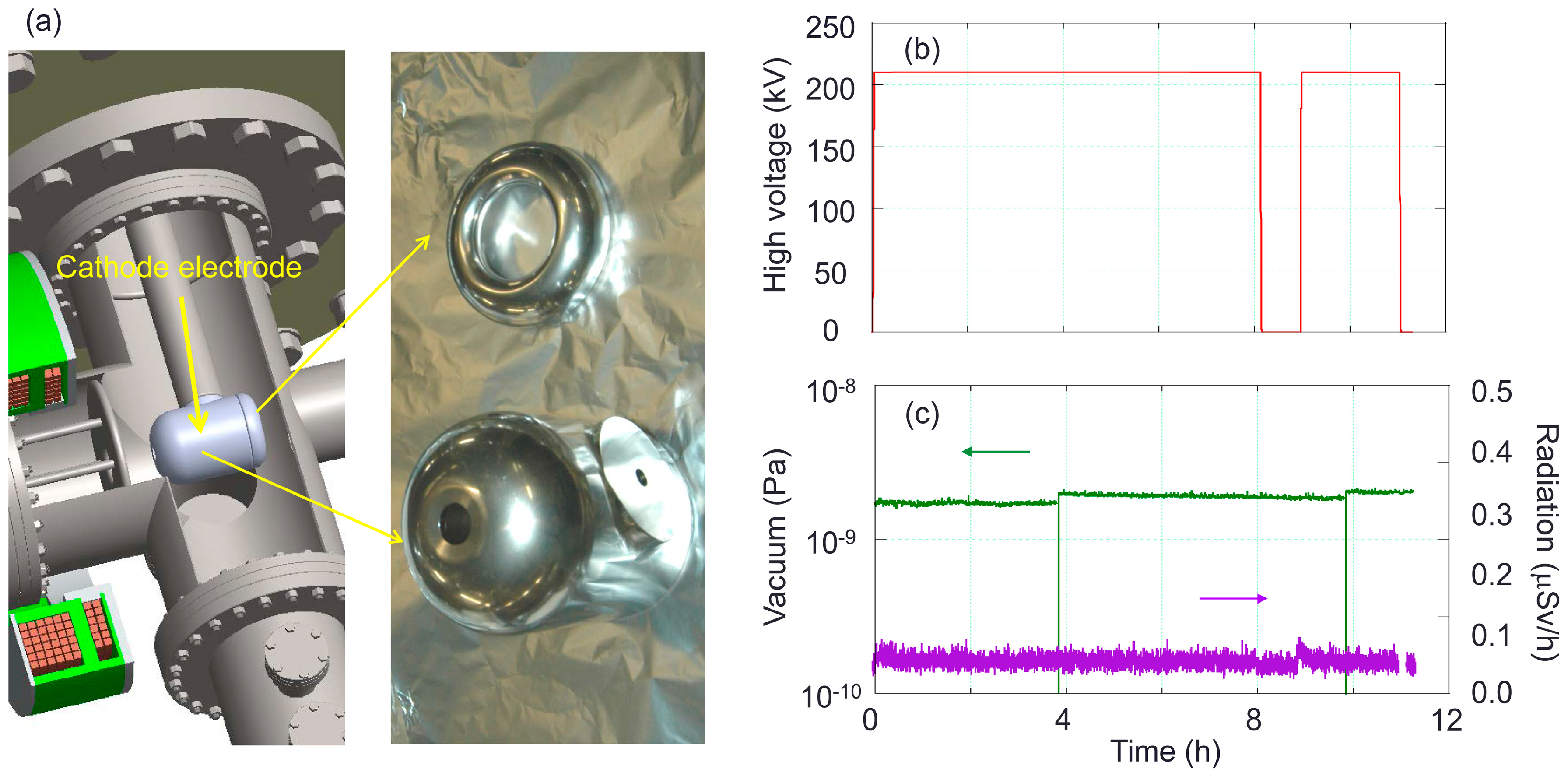
4. Photocathode Electron Gun
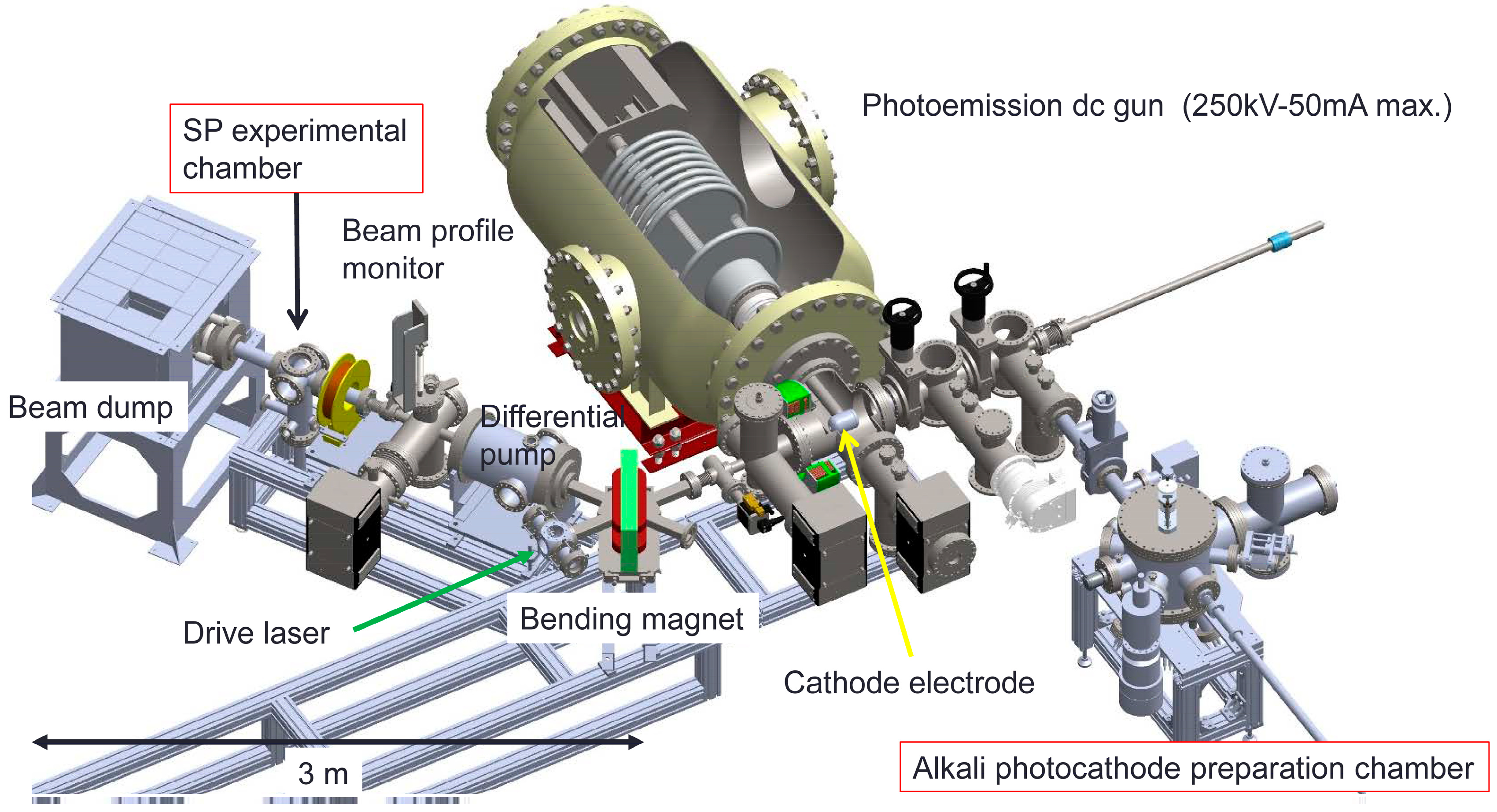
Figure 3 shows our photocathode dc electron gun system with a 250 kV-50 mA HVPS. The gun was originally developed as a dc gun equipped with a GaAs photocathode to establish fundamental technologies for high-brightness, high-current beam generation for future light sources. A 1 μA beam has been generated at 180 kV from a GaAs photocathode. The operational voltage at that time was limited to less than 180 kV because of the field emission generated from the cathode electrode. The details of the gun are described in Reference [
6]. The gun system consists of an SF
6 tank, a high-voltage chamber, and a GaAs preparation chamber. The alkali antimonide photocathode preparation system described in the previous section was connected to the GaAs preparation chamber. The gun cathode electrode was replaced to accommodate a photocathode puck compatible with the cERL and to reduce the surface electric fields for high-voltage operation. We redesigned the cathode electrode to reduce the surface electric field. The maximum cathode electric field decreased from 14 to 12 MV/m and the maximum anode electric field decreased from 8 to 6 MV/m.
Figure 4 shows a photograph of the new cathode electrode and the high-voltage holding test with the cathode electrode in place. The high voltage at 210 kV was applied for 8 h with no discharge.
We also prepared a beamline for high-current beam generation (
Figure 3). The beamline consists of a solenoid magnet followed by a bending magnet, a differential pump system, a beam profile monitor and a beam dump. The laser beam is injected through a window in the bending magnet chamber onto the photocathode. The differential pump system is used to separate the gun vacuum from the beam dump vacuum. The beam dump is water-cooled to handle the 5 kW beam power and is surrounded by lead radiation shield blocks. The transverse beam size at the beam dump is expanded by a beam expander magnet.
5. Beam Generation
The first beam generation at 150 kV was performed in April 2016, 1 week after the Cs3Sb photocathode fabrication. After the measurement of the transverse beam profile at the beam monitor, the beam current was measured at the beam dump. A resistor was connected between the ground and the beam dump which was electrically floated from the ground by a ceramic beam pipe. The resistor of 10 kΩ was used to measure the beam current less than 0.1 mA. The beam current was 1.26 μA for a laser power of 51 μW at 532 nm, corresponding to a QE of 5.8%. The QE was twice that of the value measured at the fabrication chamber, even after the photocathode was transferred to the gun chamber. This indicates that QE increased under extreme high-vacuum conditions due to progress of the chemical reaction for Cs3Sb layer formation on the surface. The QE value was derived from the beam dump current and the laser power measured in front of the bending magnet window. The high voltage was limited to 150 kV because dark current was generated when discharges occurred. These discharges were caused by small particles or dust generated from the laser injection window when the electron beam was transported to the window while the bending magnet power cable was not properly connected to the bending magnet.
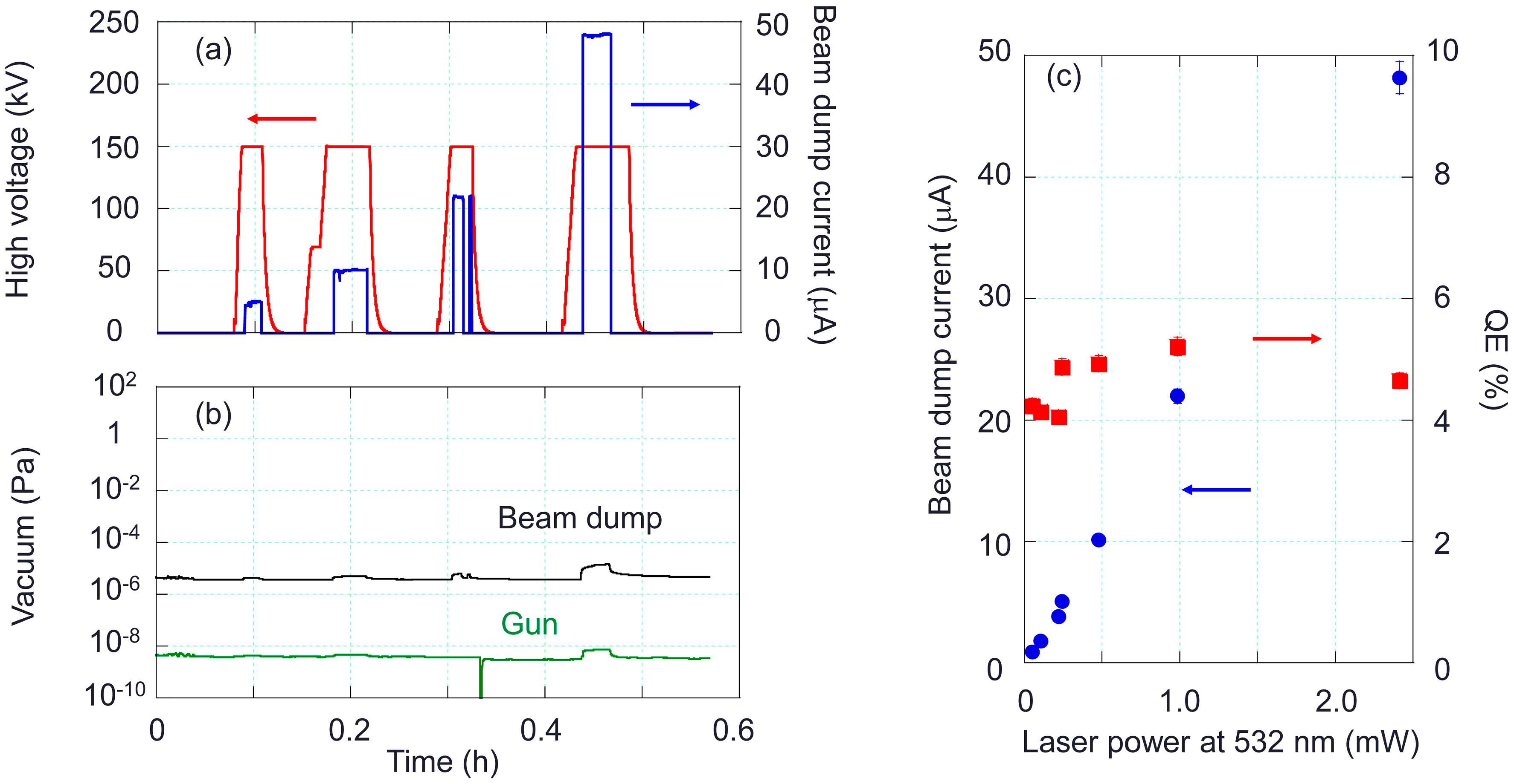
Beam generation of more than 10 μA with a 5 mW laser was performed in August 2016 after the beam dump was surrounded with lead radiation shield blocks. The beam dump current was measured as a function of laser power (
Figure 5). The beam dump current was 48 μA for a laser power of 2.4 mW at 532 nm, corresponding to a QE of 5%. This result indicates that the dark lifetime of our Cs
3Sb photocathode over four months is long and the 1/e dark lifetime of the photocathode is longer than one year. The QE value was almost constant irrespective of laser power (
Figure 5c). The gun high voltage was set to 150 kV, and the gun vacuum pressure was 4 × 10
−9 Pa when the beamline valve just after the gun is open. Although the vacuum pressure at the beam dump was three orders of magnitudes higher than that of the gun, the gun vacuum pressure roughly doubled thanks to the differential pump system.
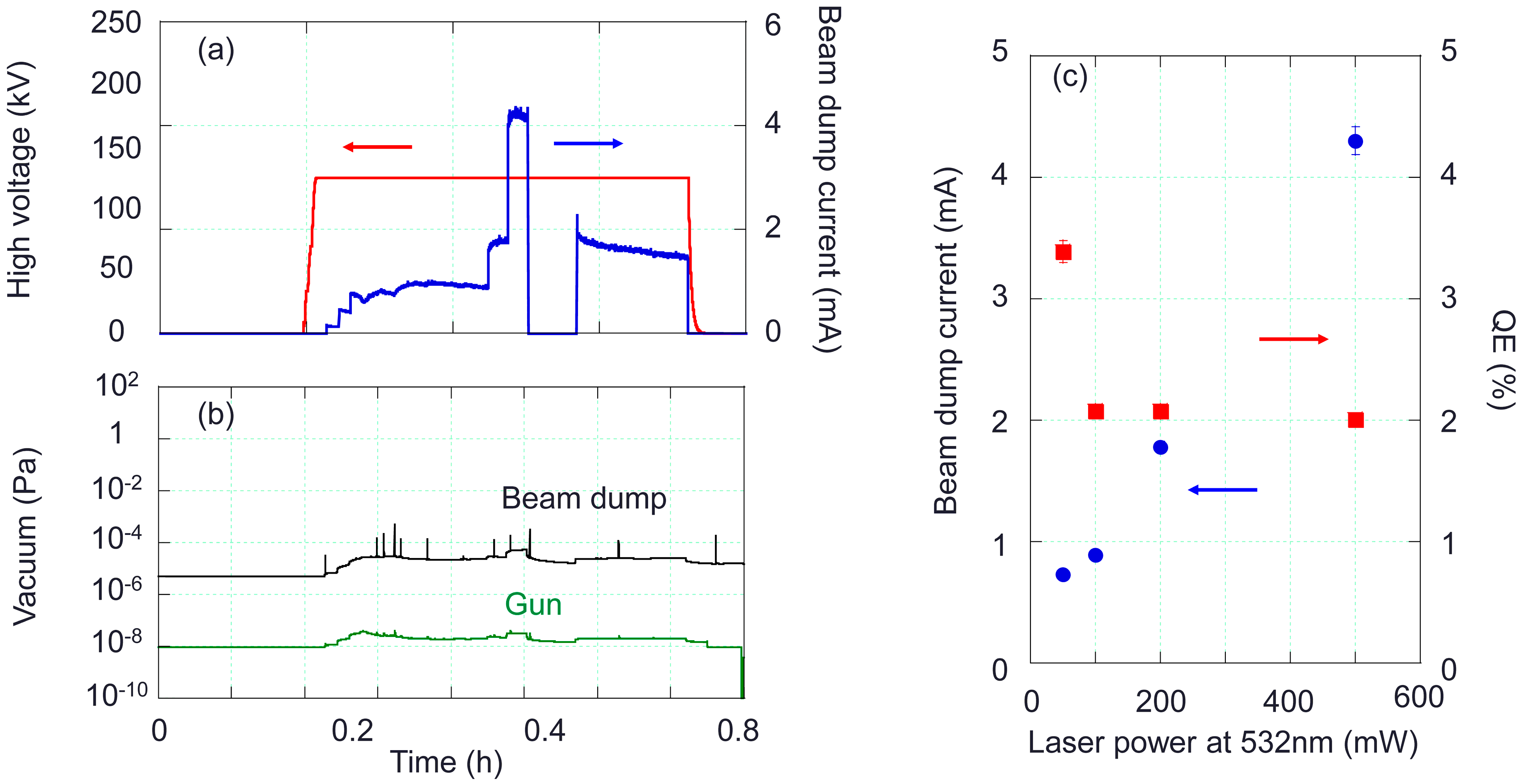
Beam generation of more than 1 mA was performed in November 2016, after we installed a 3 W laser at 532 nm and a water cooling system for the beam dump for high-current beam operation. The resistor between the beam dump and the ground for the current measurement was 1 kΩ.
Figure 6 shows the results for the high-current beam generation. A maximum beam current of 4.3 mA was achieved with a laser power of 500 mW corresponding to a QE of 2%. We tried to decrease the radiation level by adjusting the beam transport optics. When we gradually increased the beam current, a vacuum incident happened suddenly, in which the gun vacuum level went up to 1 Pa from 10
−8 Pa. A small hole was found on a bellow just downstream of the gun. We also noticed that only a 3.6 mA beam was transported to the beam dump for the 500 mW laser, whereas the beam was 4.3 mA before beam transport adjustment. Presumably, a certain amount of the beam hit the bellow and made the hole.
To get the gun system back into operation, we overhauled the vacuum system for the gun high-voltage system. Because the ceramics were exposed to 1 Pa air, we baked them to remove H2O from the surface. We also wiped the surface of the cathode electrode with a lint-free tissue to remove the sources of dark current, such as small particles. We reached 200 kV in 4 h of high-voltage conditioning after baking. This indicates that the gun can be operated at 200 kV with 10 more hours of conditioning, and that wiping the cathode electrode with a lint-free tissue helps to remove the sources of dark current.
We also re-fabricated the alkali antimonide photocathode that was exposed to 1 Pa air. The maximum QE was 0.5% and the lifetime was very short. This implies that a photocathode that has been activated and then exposed to air cannot be re-fabricated. We need to install a new wafer for fabricating Cs3Sb. We installed a beam profile monitor just after the gun to prevent further vacuum incidents.
6. Conclusions
We have developed a photocathode dc gun at QST to generate a high-current beam for the SP FEL experiment. The gun system consists of an alkali antimonide photocathode preparation chamber, a dc gun, and a beamline with a water-cooled beam dump. We fabricated a Cs3Sb photocathode with a QE of 5.8% at a wavelength of 532 nm and generated a 150 keV beam with a current of up to 4.3 mA with a 500 mW laser at 532 nm. We suffered a vacuum incident during the beam transport of a high-current beam. A well-prepared beam monitor system is necessary for no more vacuum incidents.


