Article

Empirical, Experimental and Numerical Prediction of Ground-Borne Vibrations Induced by Impact Pile Driving

by
Aires Colaço
,
Miguel Antas Ferreira
and
Pedro Alves Costa
*
Department of Construct-FEUP, University of Porto, 4200-465 Porto, Portugal
*
Author to whom correspondence should be addressed.
Vibration 2022, 5(1), 80-95; https://doi.org/10.3390/vibration5010004
Submission received: 20 December 2021 / Revised: 14 January 2022 / Accepted: 20 January 2022 / Published: 25 January 2022

Abstract

:
The automatization of construction activities, which aims to reduce the time and cost of constructions, makes impact pile driving an interesting technique. However, these activities in urban areas can generate excessive vibrations and interfere with people and structures in the vicinity. With that in mind, predicting the expected vibration levels during the project design stage is essential. Different methodologies can be employed in this task, from empirical approaches to detailed and complex numerical formulations. This paper intends to present an overview of the empirical methods and the main physics of the problem from a numerical point of view. The results obtained are then compared with experimental vibration data reported in the literature in order to discuss the adequacy of empirical and numerical methodologies in predicting ground-borne vibrations induced by impact pile driving.

1. Introduction

Civil engineering construction works can be viewed as an important source of vibrations. Even when construction is for a limited time, when performed close to buildings, the generated seismic waves can disturb people and activities, cause damages to existing equipment and, in extreme scenarios, damage surrounding structures [1,2]. The activities can include pile driving, soil excavation, site clearing, truck traffic, compaction with vibratory equipment and the removal of existing buildings, among others [3,4]. The vibration impacts are especially critical when close to advanced research centers, such as the Laser Interferometer Gravitational-Wave Observatory (LIGO) and the European Organization for Nuclear Research (CERN), and they should be monitored and their effects predicted [5,6,7]. When construction works are planned to be developed over a long period, long-term ground-motion monitoring should be carefully considered and analyzed [8].
According to the FTA [9], the highest vibration source levels associated with construction equipment are related to pile drivers used in the construction of deep foundations. As an overview, deep foundations are currently used in engineering practice to solve problems induced by poor geotechnical soil characteristics, typically shallow soil layers with low bearing capacity or low stiffness. This type of foundation is ancient, with reports of the use of timber piles in the year 800 BC [10]. Over this period, a growing number of solutions emerged, with different materials and construction techniques. Given the broad range of solutions, a possible way to classify piles is based on their installation method, whereby piles are usually classified into two categories: displacement and non-displacement piles [11]. Pre-fabricated driven piles are included in the first category, which is characterized by the occurrence of soil movements to allow for the penetration of the pile into the ground, without the need for prior removal of the soil, which characterizes the second category.
For the specific case in which the pile (pre-formed) is pushed into the ground by an impact hammer, some advantages can be noticed, such as reduced construction time and lower cost. However, this technique also has some negative environmental consequences, essentially associated with the generation of ground-borne vibrations during driving operations [12,13,14,15]. Thus, the prediction of these pernicious phenomena during the design stage of the foundations is essential. However, the difficulty of predicting these pernicious effects, in many cases, limits the applicability of the method, with harmful technical and economic effects.
As previously mentioned, the prediction of ground-borne vibrations due to impact pile driving is a complex issue involving the consideration of distinct components: hammer device, pile, soil and building. Understanding the generation and propagation of vibrations requires knowledge of the hammer device, the pile–ground dynamic interaction, the propagation waves, the soil–structure interaction, and the structural vibration, as depicted in Figure 1.
The quantification of the effects of vibration on humans and buildings is usually performed using particle vibration velocity as a primary indicator, since there is a correlation between the damage sustained by buildings and the vibration velocity experienced by the soil [1]. Given the complexity of the vibration signal, single estimators, such as peak particle velocity (PPV), are often used. The vast majority of standards and guidelines in this field specify the permitted vibration levels based on this vibration indicator. In this regard, here are some of the most important examples:
  • Swedish standard SS 25211 (Vibration and shock—Guidance levels and measuring of vibrations in buildings originating from piling, sheet piling, excavation and packing to estimate permitted vibration levels);
  • German standard DIN 4150-3 (Vibration in buildings—Part 3: Effects on structures);
  • Swiss standard SN 640 312 (Swiss Standard on vibration effects on buildings);
  • British standard BS 7385-2 (Evaluation and measurement for vibration in buildings. Part 2: Guide to damage levels from ground-borne vibration);
  • Portuguese standard NP 2704 (Evaluation of impulsive vibrations in structures);
  • Federal Transit Administration (FTA)—Transit Noise and Vibration Impact Assessment Manual.
Considering the above indications, this paper intends to present an overview of the empirical methods and the main physics of the generation and propagation of ground vibration. Advanced numerical modeling is used for a deeper understanding of the generation and propagation phenomena. The results obtained from these two methodologies are compared with the experimental results reported in the literature. To fulfil these objectives, the present paper is organized into four main sections: 1—Introduction; 2—Ground vibration induced by pile driving; 3—Experimental, empirical and numerical results—A Comparison; 4—Conclusions.

2. Ground Vibration Induced by Pile Driving

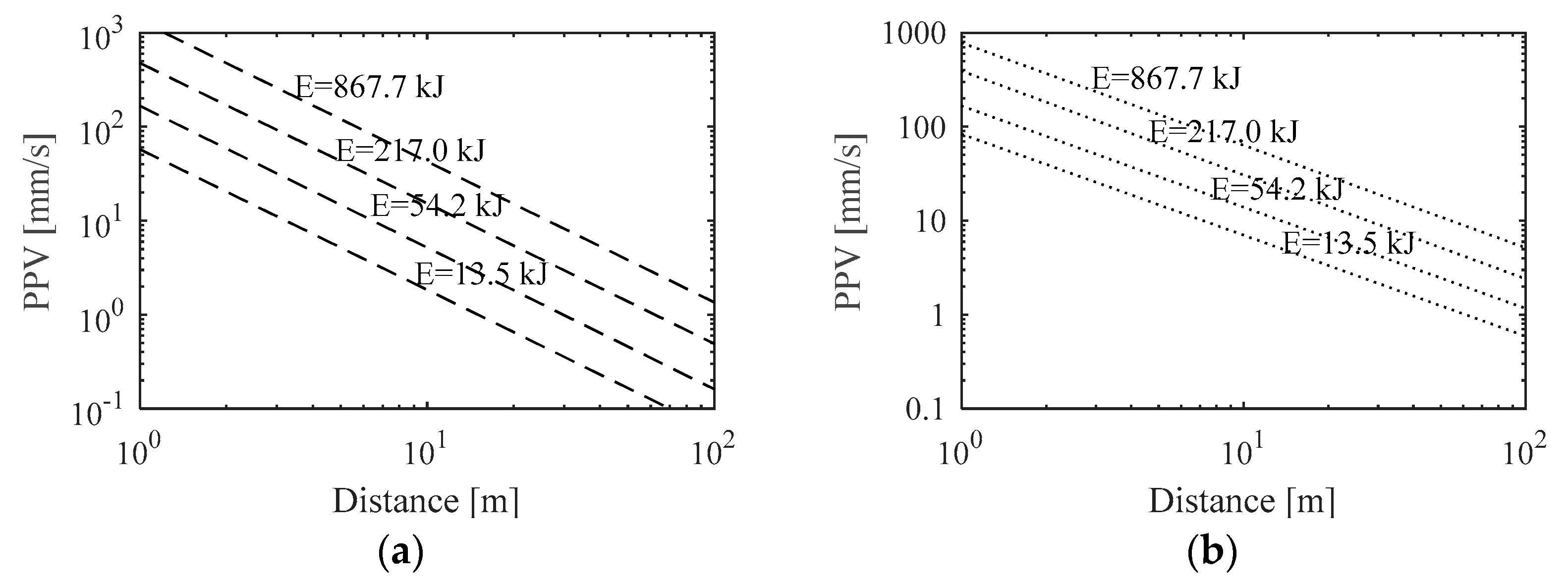
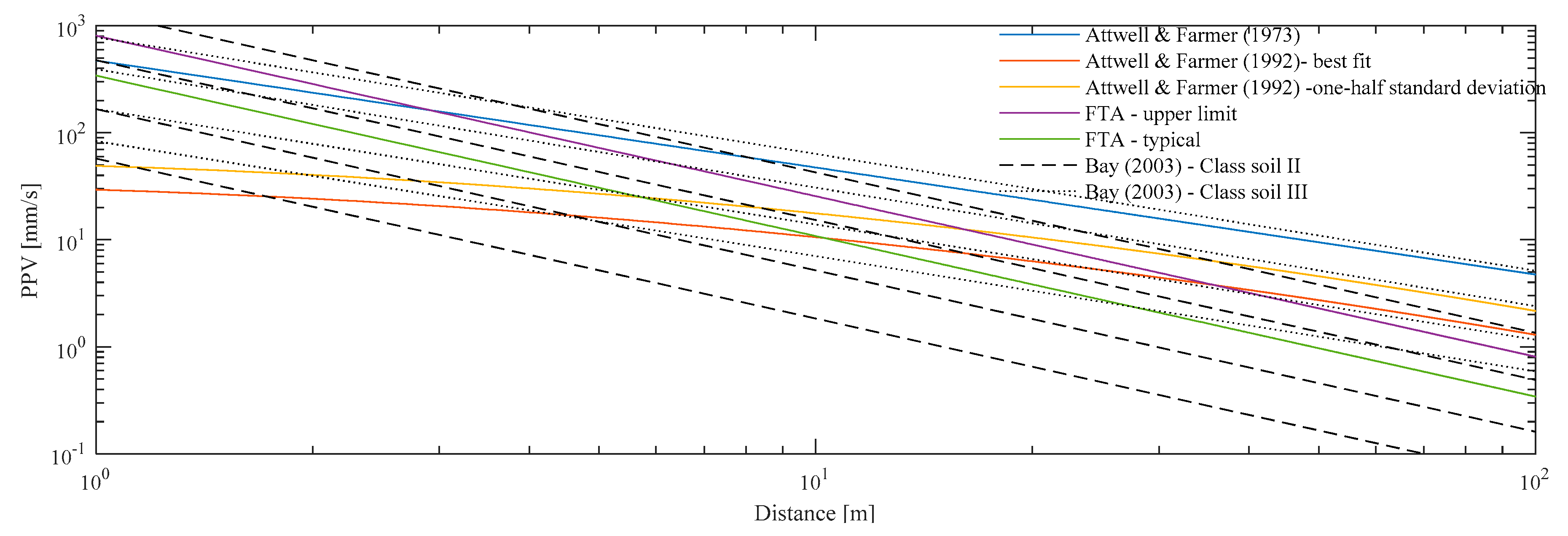
2.1. Empirical Methods for Estimating Ground Vibration

Given the complexity involved in the prediction procedure of vibrations induced by pile driving, it is common to establish empirical models for their quantification. This procedure is also used for other problems involving complex phenomena of the generation and propagation of vibrations, for example, whether they are associated with explosions, compaction work or construction equipment in general. When applied in conditions similar to those that originated them, the simplicity of the application makes them useful tools for a scope analysis, allowing a quick assessment of the maximum vibration levels.
Inspired by the work developed by Wiss [16], Attwell and Farmer [17] were the first authors to provide an empirical model for an expeditious estimation of vibration levels due to pile driving. In this approach, the peak particle velocity (PPV), v , is estimated by taking into account the energy transmitted by the hammer to the pile, as well as the distance to the observation point, as suggested by Equation (1).
v = k ( W 0 r ) x
where W 0 is the hammer energy, and r is the horizontal distance to the pile. k and x stand for empirical constants. Attwell and Farmer [9] achieved a satisfactory (and conservative) correlation with experimental results using k = 1.5 and x = 1 . Different values have been proposed by other authors in recent years [18,19,20,21].
Based on a larger database of experimental results, Attwell et al. [22] found that a linear relation in the log–log space is not strictly valid. A better fit of the empirical law to the experimental results could be reached using a quadratic regression curve:
log v = 0.519 + 1.38 log W 0 r 0.234 log 2 W 0 r
In a more conservative approach, the authors recommend adopting a one-half standard deviation line for the quadratic regression:
log v = 0.296 + 1.38 log W 0 r 0.234 log 2 W 0 r
The Federal Railroad Administration (FTA) [9] also proposed an empirical law to predict vibration levels caused by construction activities in general. As defined by Equation (4), the peak particle velocity ( v ) results from the distance between the source and the receiver ( r ) and considers a reference vibration level of the construction equipment ( v r e f ) at a reference distance ( r r e f ).
v = v r e f ( r r e f r ) 1.5
Regarding impact pile driving activities in particular, the FTA [9] defines two reference values for vibration levels, and they are presented in Table 1.
Another example of an empirical prediction law is reported by the FHWA [10], in which the relationships between the peak particle velocity and the distance from the pile formulated by Bay [23] are summarized according to the rated hammer energy for two classes of soil: Class II (competent soils with standard penetration test N values of 5–15 blows per 0.3 m) and Class III (hard soils with SPT N values of 15–50 blows per 0.3 m). The curves associated with these empirical relationships are depicted in Figure 2, where, generally, an increase in vibration levels is observed along with the increase in ground stiffness and hammer energy.
Given the particularities of each empirical model, it is important to perform a general comparison between them. Therefore, Figure 3 presents an overview of the peak particle velocity levels according to the pile–receiver distance obtained from the previous empirical approaches. A rated energy equal to 100 kJ was considered for the empirical models proposed by Attwell and Farmer [17] and Attwell et al. [22].
From an engineering perspective, the high variability in the vibration levels predicted by the different empirical models can make the prediction procedure more complex. In fact, choosing an expected value is so difficult that decision makers may be forced to choose too wide a range of values, which can be highly penalizing for the driving method.

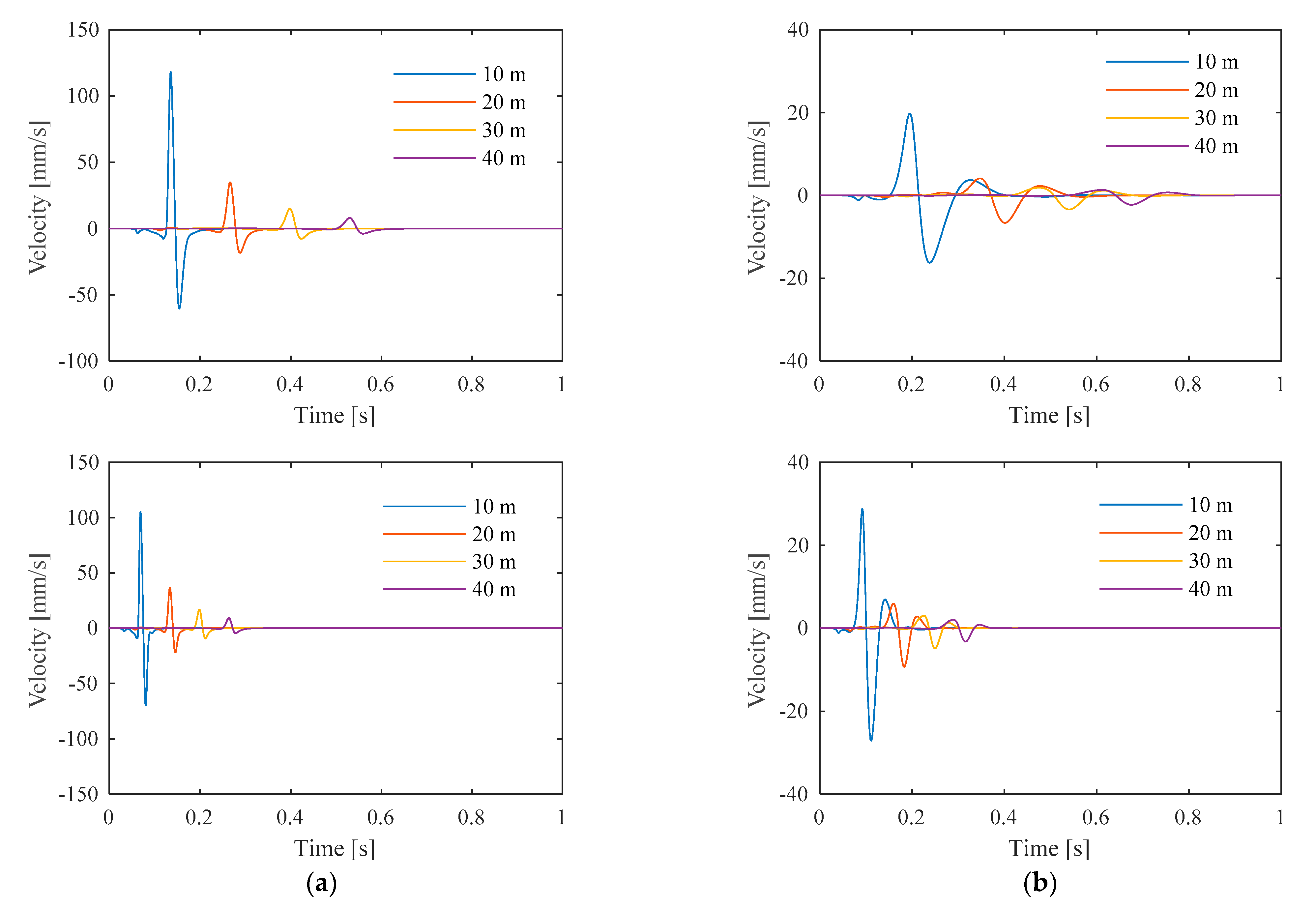
2.2. Modeling of Ground Vibration

2.2.1. Generalities

In search of a deeper understanding of the physics connected to the generation and propagation of vibrations from impact pile driving and a more general prediction tool, one that is not constrained by the particular conditions for which the empirical rules were defined, numerical models can be seen as versatile tools to address the problem in a general way. Different numerical methods associated with this topic can be found in the literature. Ramshaw et al. [24] and Khoubani et al. [25] proposed an axisymmetric model based on finite/infinite elements to simulate the pile–ground system. A similar modeling technique, but this time using artificial boundaries based on a gradual increase in soil damping to simulate the Sommerfeld’s condition, was presented by Homayoun Rooz and Hamidi [26]. Following a similar strategy for the treatment of artificial boundaries, Sofiste et al. [27] recently proposed a computational model based on an explicit time-domain analysis. Considering high soil strain levels in the vicinity of the pile, inducing a non-linear behavior of the soil, Masoumi et al. [28] presented a non-linear coupled finite element–boundary element approach to predict free-field vibrations induced by vibratory and impact pile driving. Moreover, also including the non-linear behavior of the soil, Grizi [29] used the commercial software Plaxis 3D to compute the vibration fields induced by impact pile driving.

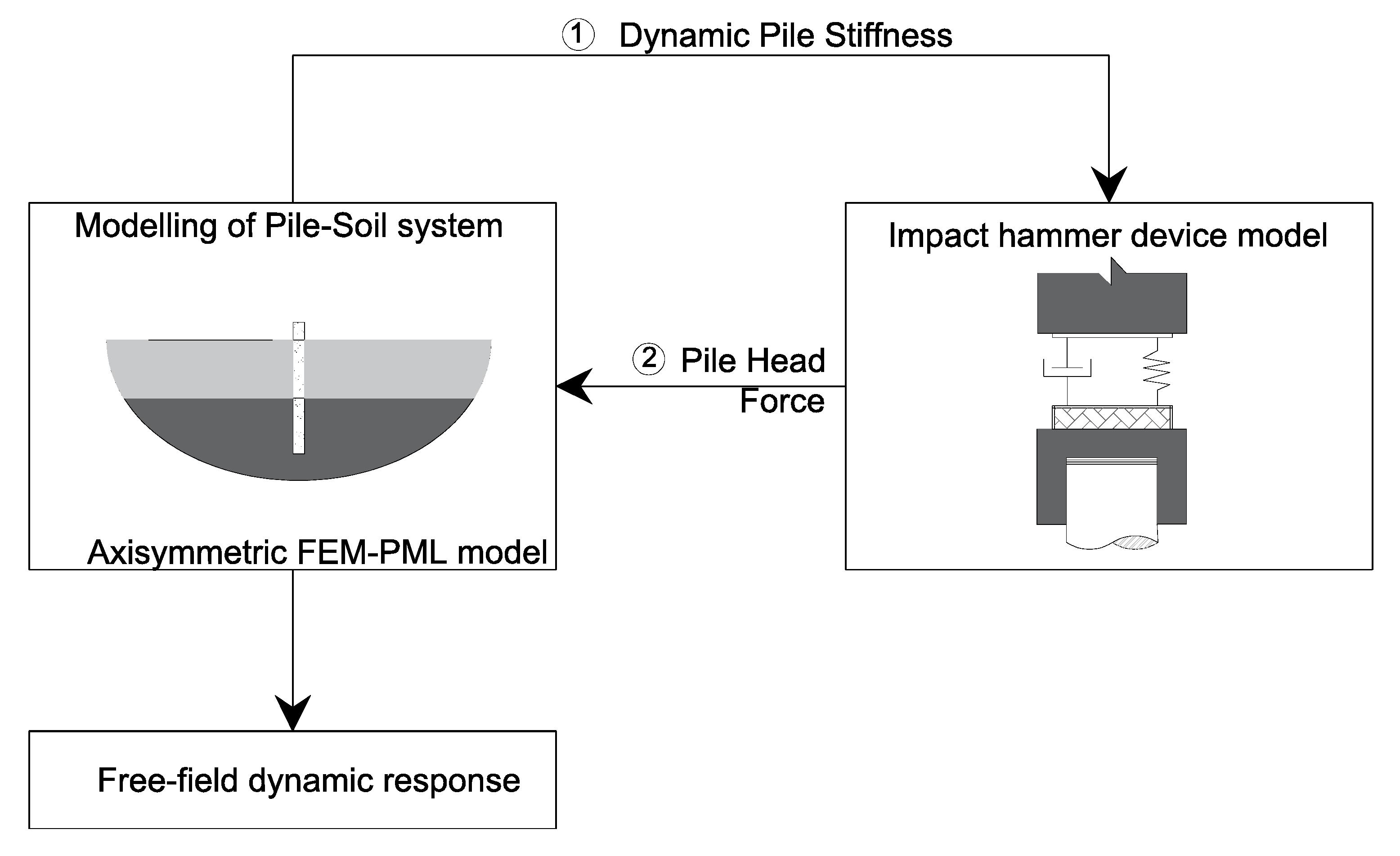
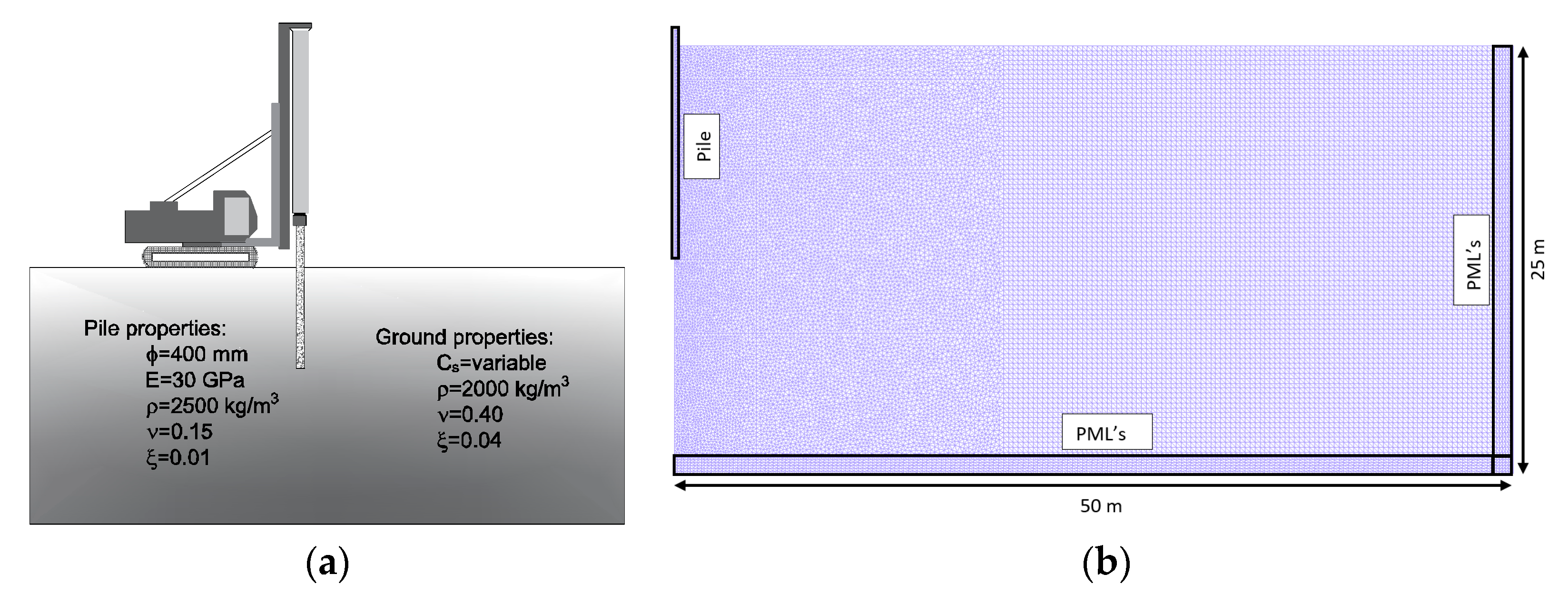
2.2.2. Modeling Approach

As the authors are aware of the recent developments achieved in numerical simulations, they proposed an efficient numerical approach for the prediction of vibrations induced by impact pile driving [30]. In a simple and general way, the approach, formulated in the frequency domain, is split into two main modules: one comprising the pile–ground system, modeled by an axisymmetric FEM-PML approach; the other regarding the dynamic simulation of the hammer device. Since there is a dynamic interaction problem between the hammer device and the remaining system, the two models are coupled, meeting the equilibrium and compatibility requirements, as shown in Figure 4.
From the literature, it is clear that the non-linear behavior of the soil near the pile greatly influences the generated vibration field. As observed in Figure 5, pile driving operations induce soil strain levels higher than the compatible elastic limit [30]. For a horizontal distance of up to 10 times the diameter of the pile, the octahedral strain levels are even higher than 10−3, well above the limit generally considered acceptable for the elastic domain.
However, non-linear analyses cannot be developed in the frequency domain, as they require time-domain schemes that are often challenging in terms of computational efficiency. In order to consider the effect of soil non-linearity as a result of the strain level, an equivalent linear analysis can be integrated into the modeling approach. Therefore, the effects of the non-linear behavior of the soil can be incorporated in a simplified but reliable way. This technique addresses an iterative method that compensates for the inelastic behavior by adjusting the parameters of the elastic material to the significant strain levels. The accurate modeling of stiffness degradation according to the strain level is a key feature for the success of this iterative technique. Additional details about the procedure can be found in Colaço et al. [30].

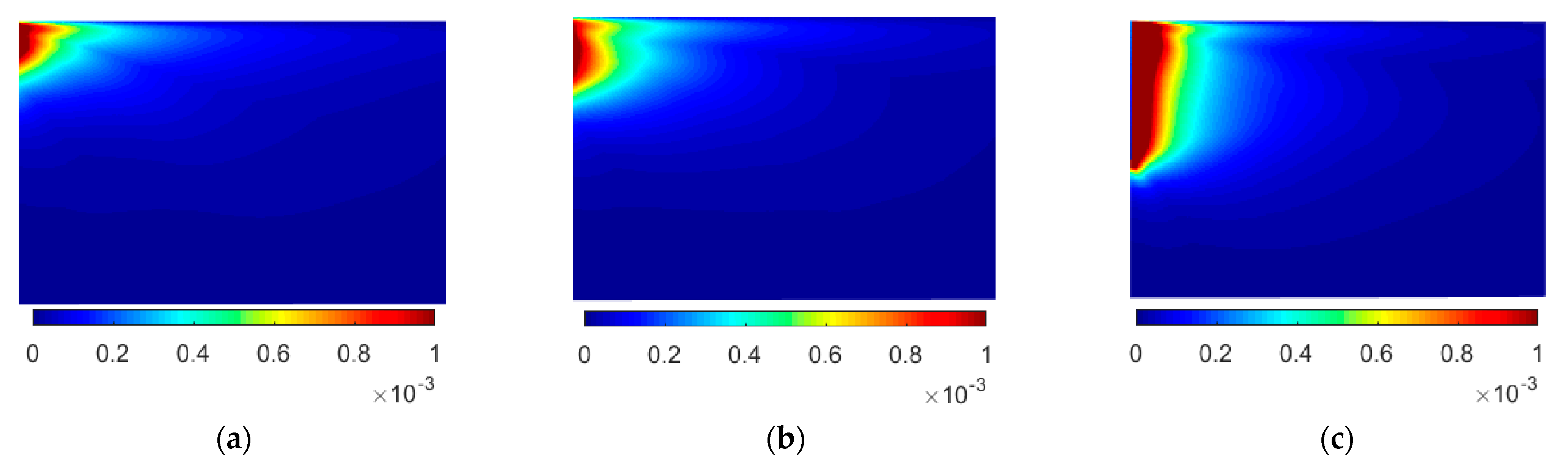
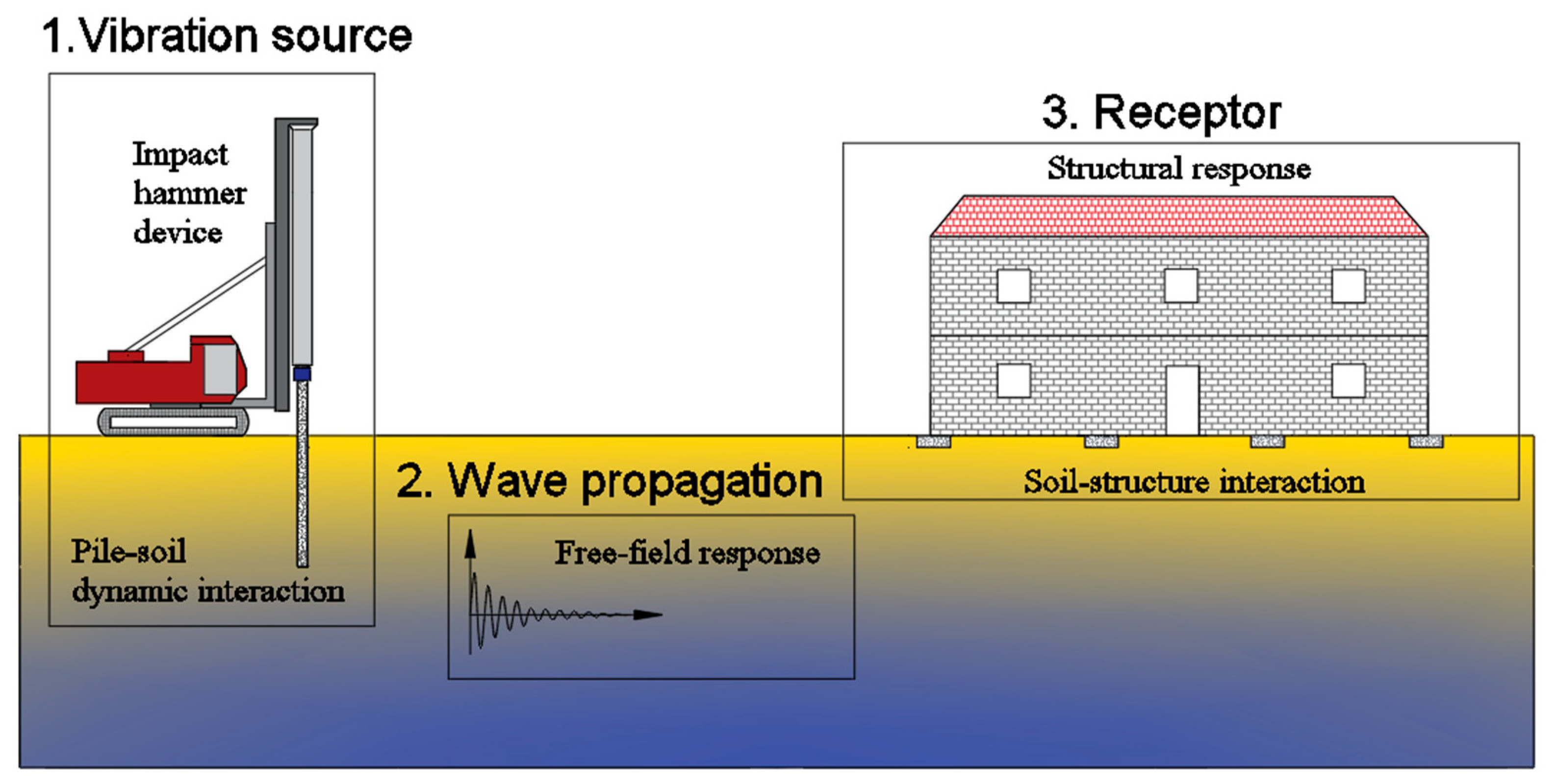
2.2.3. Physics of the Generation and Propagation of Ground Vibration

This section presents a general discussion about the main behavior trends of the system in terms of driving depth, ground stiffness and impact force magnitude. Parametric studies consider three different values of ground stiffness, according to an S-wave velocity (Cs) equal to 80 m/s, 120 m/s and 160 m/s; three driving depths scenarios, with penetration depths (Z) of 2.5 m, 5 m and 10 m; and three impact force magnitudes, corresponding to a height of fall (H) of 0.25 m, 0.50 m and 0.75 m. The combination of the different variables is summarized in Table 2.
Regarding the numerical simulation of the pile–ground system, an FE-PML mesh consisting of 48,116 triangular elements with 6 nodes (total nodes—96,969) is considered, corresponding to a discretized cross-section of 50 × 25 m2. The pile has a total length of 10 m and is made of precast concrete, with a Young’s modulus, E, of 30 GPa and a mass density, ρ, of 2500 kg/m3. A hysteretic damping factor of 0.01 and a Poisson’s ratio equal to 0.15 are also considered for the pile. Figure 6 shows an overview of the configuration, properties and mesh adopted for the numerical example.
Regarding the driving device, a hydraulic impact hammer with a ram mass (mr) of 7 tonnes was considered. An anvil mass (ma) equal to 490 kg was also used. The hammer cushion has a stiffness value of kc = 2 × 10⁶ kN/m and a damping value of 588 kNs/m. A loss coefficient is considered to meet energy losses of about 0.05.
As previously discussed, the non-linear behavior of the soil near the pile plays a relevant role in the generated vibration field, and the analysis should take this effect into account. In the present application example, an equivalent linear methodology is adopted to take this behavior into consideration. Additionally, and from a purely theoretical perspective, the numerical analysis can be performed using an elastic-linear approach, i.e., neglecting the degradation of soil stiffness and the increase in damping according to the strain level, as observed in Figure 7. Thus, a comparative study between a linear and an equivalent linear analysis of the medium is performed.
Following the objectives initially set, the first part of the analysis intends to evaluate the influence of soil stiffness. Figure 8 shows the time history of the vertical velocity of the particles at four points located on the surface of the ground and for horizontal distances to the center of the pile of 10 m, 20 m, 30 m and 40 m. As expected, the vibration amplitude tends to attenuate as the distance to the pile increases. Due to the geometric attenuation and material damping, this effect is observed regardless of the type of analysis performed. However, peak vibration values are higher when a linear behavior of the system is assumed.
The frequency content of the vertical velocity of the particle is plotted in Figure 9 for the scenarios under analysis. It is possible to see that there is a tendency for a higher concentration of energy in lower frequency ranges and softer soils. This concentration of energy is also verified as the distance from the receiver to the pile increases. This is essentially justified by the material damping, which introduces a greater attenuation in the higher frequency range.
The frequency range observed in the vertical velocity under free-field conditions is quite relevant when dealing with the dynamic response of existing nearby buildings. Since building slabs typically have a resonant frequency ranging from 15 Hz to 35 Hz, large amplifications can be expected [32,33].
The differences found between the linear and the equivalent linear results are essentially related to the degradation of stiffness and the increase in the material damping, according to the level of strain, provided by the equivalent linear analysis.
Considering the three values of soil stiffness previously defined, Figure 10 presents the evolution of the peak particle velocity according to the distance from the pile. As observed, higher vibration levels are associated with stiffer soils. There is only one exception associated with the linear analysis and for shorter distances. However, for greater distances, this trend is reversed.
This evidence is related to material damping. In fact, for the same excitation frequency, the greater the stiffness of the ground, the greater the generated wavelength. Therefore, the dissipation of energy along the path from the source to the receiver is more evident on softer soils than on stiffer soils.
Regarding the influence of the pile penetration depth (Figure 11), when dealing with the linear approach, lower penetration depths lead to higher levels of vibration. The same clarity is not found in the results provided by an equivalent linear approach. However, the authors should clarify that these comments are valid for a homogeneous ground. When a layered ground is considered, an additional complexity is involved, and a detailed analysis is recommended.
For a deeper analysis of the wave patterns in the ground derived from the pile penetration depth, Figure 12 represents the norm of the particle velocity at two distinct time steps and for scenarios 1.2 and 1.8 (see Table 2). As observed, the propagation of body waves around the pile toe with a spherical wave front is visible at the earlier instance for both scenarios. In the case where the pile embedment depth is equal to 10 m, the propagation of vertically polarized shear waves that arise around the pile shaft and propagate on a cylindrical wave front is also evident.
At the second time step, the prevalence of Rayleigh waves along the ground surface is evident with a velocity slightly lower than that of the shear waves. These waves attenuate exponentially with depth, which results in larger vibration velocities at the surface of the ground when compared with deeper locations.
The magnitude of the vibration levels is directly related to the energy involved in the driving process. As represented Figure 13, as the height of the fall increases, the vibration level also increases. This observation is valid for the linear and equivalent linear approaches.

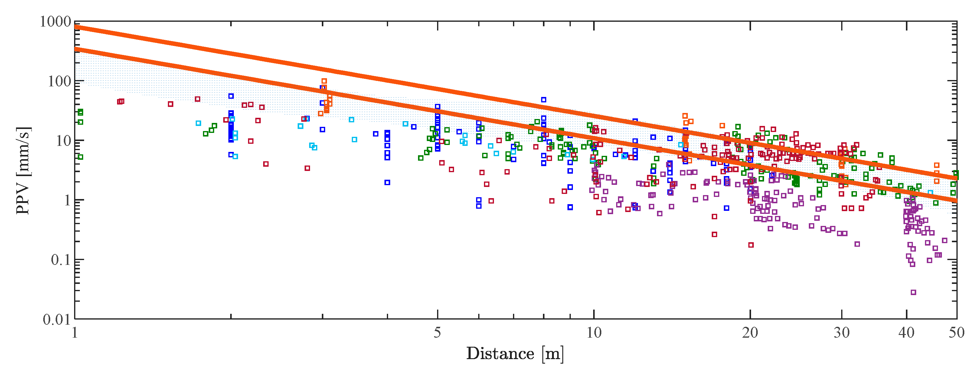
3. Experimental, Empirical and Numerical Results—A Comparison

The suitability of the empirical and numerical methodologies for the prediction of ground-borne vibrations induced by impact pile driving can be verified by comparing the results provided by these approaches with experimental data. In recent years, some experimental measurements of vibrations have been reported in the literature. However, the results are widely dispersed, and, sometimes, relevant information, such as the type of soil or the type of hammer, is missing, which hinders the ability to compare them.
For a global comparison between numerical, empirical and experimental results, the authors intend to evaluate, in the first step, the dispersion of the experimental results in order to find a representative level of the vertical velocity of vibration according to the distance. A total of six works are considered in this systematization, comprising the records obtained from the driving of 15 piles. Without going into too much detail, a general description of the reported cases can be given:
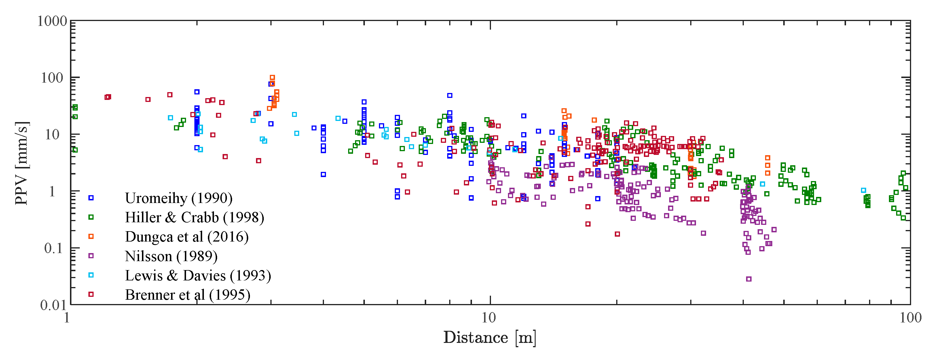
  • Uromeihy [34]: records from impact driving of five steel piles (four H-sections and one sheet pile);
  • Hiller and Crabb [35]: records from impact driving of two steel piles (one H-section and one sheet pile);
  • Lewis and Davie [36]: records from impact driving of one precast concrete pile (section 360 mm × 360 mm) and one H-section steel pile;
  • Dungca et al. [37]: records from impact driving of one precast concrete pile (section 450 mm × 450 mm);
  • Nilsson [38]: records from impact driving of one precast concrete pile (section 450 mm × 450 mm) and two steel piles (tubular profiles);
  • Brenner and Chittkuladilok [39]: records from impact driving of two precast concrete piles (sections 425 mm × 425 mm and 260 mm × 260 mm).
In addition to the different types and sections of the piles, the reported cases are also characterized by a high variability in the geotechnical conditions and energy involved in the driving process. Despite these differences, the idea is to present typical values of the maximum velocity of vibration involved in the phenomenon. Thus, Figure 14 presents a compilation of the maximum vertical velocities of vibration according to the horizontal distance to the pile.
As observed, there is great variability in the peak vertical velocity, even for piles reported by the same author. This variability can be attributed to the different conditions involved in the experiments, such as the type and section of the pile, the properties of the ground or the impact energy involved.
In Figure 15, the previous results are plotted against cosmetic and structural damage thresholds provided by the Portuguese national standard NP2074 for various types of structures and for the dominant frequency in the interval between 10 Hz and 40 Hz. As initially set, the reported phenomenon has the potential to induce some damage to structures when the distances between the pile and the receiver are relatively reduced. This condition is more critical for structures in poor conditions. Concerning the disturbance, according to the limits presented by the FHWA [10], the effects are more relevant, even at greater distances from the source of impact. Despite these general trends, it should be noted that projections for another site should be carefully analyzed.
For a general comparison, the numerical curves presented in the previous section were plotted against the experimental results. Comprising the most common characteristics of the impact hammer [40], the previous scenarios reported in Table 2 were repeated considering a ram mass of 5 t, instead of 7 t, as initially assumed. Furthermore, the empirical curves provided by the FTA [9] are also represented (remember that these curves do not depend on the driving energy). An overview is presented Figure 16.
In terms of the numerical results, as discussed before, the linear methodology usually overestimated the PPV. Its consideration in the prediction procedure could be the first step to estimating the expected vibration levels, leading to a conservative prediction.
The envelope zone provided by the equivalent linear analyses provides, in general, an upper limit for the represented experimental results. However, it should be noted that the conditions of the analysis are not entirely compatible with the experimental results. In fact, the intention of this work is to perform a general comparison.
Concerning the empirical methods, the curves defined by the FTA also show a reasonable adherence to the experimental results. As represented, and for pile–receiver distances greater than 10 m, the FTA upper curve is very close to the upper limit of the numerical envelope resulting from the equivalent linear approach. Despite this good agreement, a critical analysis should be performed for each practical application.

4. Conclusions

The present paper summarizes the phenomenon of vibrations induced by impact pile driving from experimental, empirical and numerical points of view. Initially, a systematization of the most relevant empirical approaches was presented. The results confirm the high variability of vibration levels predicted by the different approaches, hindering the prediction procedure. Alternatively, the prediction procedure can be improved using numerical modeling. Its consideration also allows for the study of the influence of the main variables involved in the vibration generation mechanism, such as the stiffness of the ground, the driving depth and the magnitude of the impact force.
This numerical analysis highlighted the fact that the effects of the non-linear behavior of the soil are relevant to this type of problem. These effects can be incorporated by an equivalent linear approach, in which an iterative technique adjusts the parameters of the elastic model to significant strain levels. The comparison of the results obtained in the parametric studies with a generic set of experimental measurements showed the suitability of the proposed approach for the prediction of ground-borne vibrations induced by impact pile driving.
As a final conclusion, the reported phenomenon has the potential to cause cosmetic or even structural damage to surrounding buildings. Thus, it is necessary to be aware of the vibration levels induced at the base of the surrounding buildings in order to avoid excessive discomfort for residents and damage to nearby buildings.

Author Contributions

Conceptualization, P.A.C. and A.C.; methodology, P.A.C. and A.C; software, M.A.F.; validation, A.C. and M.A.F.; formal analysis, A.C.; investigation, A.C. and M.A.F.; resources, P.A.C. and A.C.; writing—original draft preparation, A.C.; writing—review and editing, P.A.C.; visualization, P.A.C.; supervision, P.A.C.; project administration, P.A.C.; funding acquisition, P.A.C. All authors have read and agreed to the published version of the manuscript.

Funding

This work was financially supported by Base Funding-UIDB/04708/2020 and Programmatic Funding-UIDP/04708/2020 of the CONSTRUCT-Instituto de I&D em Estruturas e Construções—funded by national funds through the FCT/MCTES (PIDDAC); Project PTDC/ECI-CON/29634/2017-POCI-01-0145-FEDER-029634—funded by FEDER funds through COMPETE2020-Programa Operacional Competitividade e Internacionalização (POCI) and by national funds (PIDDAC) through FCT/MCTES.
Vibration 05 00004 i001

Conflicts of Interest

The authors declare no conflict of interest.

References

  1. Chameau, J.-L.; Rix, G.J.; Empie, L. Measurement and Analysis of Civil Engineering Vibrations. In Proceedings of the 4th International Conference on Case Histories in Geotechnical Engineering, St. Louis, MO, USA, 8–15 March 1998. [Google Scholar]
  2. Svinkin, M.R. Minimizing Construction Vibration Effects. Pract. Period. Struct. Des. Constr. 2004, 9, 108–115. [Google Scholar] [CrossRef]
  3. JS-HELD-UNIVERSITY. The Impact of Construction Vibration on Adjacent Structures. 2019. Available online: https://assets.jsheld.com/uploads/The-Impact-of-Construction-Vibration-on-Adjacent-Structures.pdf?mtime=20200514134250&focal=none (accessed on 19 December 2021).
  4. Amick, H.; Gendreau, M. Construction Vibrations and Their Impact on Vibration-Sensitive Facilities. In Proceedings of the 6th ASCE Construction Congress, Orlando, FL, USA, 20–22 February 2000. [Google Scholar]
  5. Scislo, L.; Guinchard, M. Source based measurements and monitoring of ground motion conditions during civil engineering works for high luminosity upgrade of the LHC. In Proceedings of the 26th International Congress on Sound and Vibration, ICSV 2019, Montreal, QC, Canada, 7–11 July 2019. [Google Scholar]
  6. Guinchard, M.; Cabon, M.; Charrondière, C.; Develle, K.; Fessia, P.; Lacny, L.; Wenninger, J. Investigation and Estimation of the LHC Magnet Vibrations Induced by HL-LHC Civil Engineering Activities. In Proceedings of the 9th International Particle Accelerator Conference (IPAC’18), Vancouver, BC, Canada, 29 April–4 May 2018. [Google Scholar]
  7. Cabon, M.; Develle, K.; Guinchard, M. Ground Vibration Monitoring at CERN as Part of the International Seismic Network. In Proceedings of the 16th International Conference on Accelerator and Large Experimental Control Systems (ICALEPCS’17), Barcelona, Spain, 8–13 October 2017. [Google Scholar]
  8. Łacny, Ł.; Ścisło, Ł.; Guinchard, M. Application of probabilistic power spectral density technique to monitoring the long-term vibrational behaviour of cern seismic network stations. Vib. Phys. Syst. 2020, 31, 1–7. [Google Scholar]
  9. Quagliata, A.; Ahearn, M.; Boeker, E.; Roof, C.; Meister, L.; Singleton, H. Transit Noise and Vibration Impact Assessment Manual; Federal Transit Administration-Department of Transportation, Office of Planning and Environment: Washington, DC, USA, 2018. [Google Scholar]
  10. FHWA. Design and Construction of Driven Pile Foundations; Report No. FHWA-NHI-16-009; Federal Highway Administratio: Washington, DC, USA, 2016. [Google Scholar]
  11. Fernandes, M.M. Analysis and Design of Geotechnical Structures, 1st ed.; CRC Press: Boca Raton, FL, USA, 2020. [Google Scholar]
  12. Hindmarsh, J.J.; Smith, W.L. Quantifying construction vibration effects on daily radiotherapy treatments. J. Appl. Clin. Med. Phys. 2018, 19, 733–738. [Google Scholar] [CrossRef] [PubMed] [Green Version]
  13. Rahman, N.A.A.; Musir, A.A.; Dahalan, N.H.; Ghani, A.N.A.; Khalil, M.K.A. Review of Vibration Effect during Piling Installation to Adjacent Structure. AIP Conf. Proc. 2017, 1901, 110009. [Google Scholar]
  14. Athanasopoulos, G.A.; Pelekis, P.C. Ground vibrations from sheetpile driving in urban environment: Measurements, analysis and effects on buildings and occupants. Soil Dyn. Earthq. Eng. 2000, 19, 371–387. [Google Scholar] [CrossRef]
  15. Massarsch, K.R.; Fellenius, B.H. Ground vibrations from pile and sheet pile driving. Part 1 Building Damage. In Proceedings of the DFIEFFC International Conference on Piling and Deep Foundations, Stockholm, Sweden, 21–23 May 2014; pp. 131–138. [Google Scholar]
  16. Wiss, J.F. Damage Effects of Pile Driving Vibration. Highw. Res. Board 1967, 155, 14–20. [Google Scholar]
  17. Attewell, P.B.; Farmer, I.W. Attenuation of ground vibrations from pile driving. Ground Eng. 1973, 6, 4. [Google Scholar]
  18. Whyley, P.J.; Sarsby, R.W. Ground borne vibration from piling. Ground Eng. 1992, 25, 32–37. [Google Scholar]
  19. Hiller, D.M.; Hope, V.S. Groundborne Vibration Generated by Mechanized Construction Activities. Proc. Inst. Civ. Eng. Geotech. Eng. 1998, 131, 223–232. [Google Scholar] [CrossRef]
  20. ArcelorMittal. Piling Habdbook, 9th ed.; ArcelorMittal Commercial RPS: Esch-sur-Alzette, Luxembourg, 2016. [Google Scholar]
  21. Massarsch, K.R.; Fellenius, B.H. Engineering assessment of ground vibrations caused by impact pile driving. Geotech. Eng. 2015, 46, 54–63. [Google Scholar]
  22. Attewell, P.B.; Selby, A.R.; O’Donnell, L. Tables and graphs for the estimation of ground vibration from driven piling operations. Geotech. Geol. Eng. 1992, 10, 61–85. [Google Scholar] [CrossRef]
  23. Bay, J.A. A Summary of the Research on Pile Driving Vibrations. In Proceedings of the Pile Driving Contractor’s Association, 7th Annual Winter Roundtable, Atlanta, GA, USA, 21–22 February 2003. [Google Scholar]
  24. Ramshaw, C.L.; Selby, A.R.; Bettess, P. Ground Waves Generated by Pile Driving, and Structural Interaction. In Proceedings of the International Conferences on Recent Advances in Geotechnical Earthquake Engineering and Soil Dynamics, St. Louis, MO, USA, 30 March 2001. [Google Scholar]
  25. Khoubani, A.; Ahmadi, M.M. Numerical study of ground vibration due to impact pile driving. Proc. Inst. Civ. Eng. Geotech. Eng. 2014, 167, 28–39. [Google Scholar] [CrossRef]
  26. Homayoun Rooz, A.F.; Hamidi, A. A numerical model for continuous impact pile driving using ALE adaptive mesh method. Soil Dyn. Earthq. Eng. 2019, 118, 134–143. [Google Scholar] [CrossRef]
  27. Sofiste, T.V.; Godinho, L.; Costa, P.A.; Soares, D.; Colaço, A. Numerical modelling for prediction of ground-borne vibrations induced by pile driving. Eng. Struct. 2021, 242, 112533. [Google Scholar] [CrossRef]
  28. Masoumi, H.R.; François, S.; Degrande, G. A non-linear coupled finite element-boundary element model for the prediction of vibrations due to vibratory and impact pile driving. Int. J. Numer. Anal. Methods Geomech. 2009, 33, 245–274. [Google Scholar] [CrossRef]
  29. Grizi, A.; Athanasopoulos-Zekkos, A.; Woods, R.D. H-Pile Driving Induced Vibrations: Reduced-Scale Laboratory Testing and Numerical Analysis. In Proceedings of the IFCEE 2018, Orlando, FL, USA, 5–10 March 2018. [Google Scholar]
  30. Colaço, A.; Costa, P.A.; Parente, C.M.; Cardoso, A.S. Ground-borne noise and vibrations in buildings induced by pile driving: An integrated approach. Appl. Acoust. 2021, 179, 108059. [Google Scholar] [CrossRef]
  31. Ishibashi, I.; Zhang, X. Unified dynamic shear moduli and damping ratios of sand and clay. Soils Found. 1993, 33, 182–191. [Google Scholar] [CrossRef] [Green Version]
  32. Lopes, P.; Ruiz, J.F.; Costa, P.A.; Rodríguez, L.M.; Cardoso, A.S. Vibrations inside buildings due to subway railway traffic. Experimental validation of a comprehensive prediction model. Sci. Total Environ. 2016, 568, 1333–1343. [Google Scholar] [CrossRef]
  33. Colaço, A.; Costa, P.A.; Amado-Mendes, P.; Godinho, L. Prediction of Vibrations and Reradiated Noise Due to Railway Traffic: A Comprehensive Hybrid Model Based on a Finite Element Method and Method of Fundamental Solutions Approach. J. Vib. Acoust. Trans. ASME 2017, 139, 061009. [Google Scholar] [CrossRef]
  34. Uromeigy, A. Ground Vibration Measurements with Special Reference to Pile Driving. Ph.D. Thesis, Durham University, Durham, UK, 1990. [Google Scholar]
  35. Hiller, D.M.; Crabb, G.I. Groundborne Vibration Caused by Mechanised Construction Works. Noise Vib. Worldw. 2001, 32, 9–14. [Google Scholar]
  36. Lewis, M.R.; Davie, J.R. Vibrations due to pile driving. In Proceedings of the 3rd International Conference on Case Histories on Geotechnical Engineering, St. Louis, MO, USA, 1 June 1993. [Google Scholar]
  37. Dungca, J.R.; Acosta, D.Y.; Juego, M.B.; Sanchez, H.M.; Sanchez, I.S. The propagation behavior of pile-driving-induced vibration done on soil at varying distances and its effects on existing structures. Int. J. Geomate 2016, 10, 1877–1883. [Google Scholar]
  38. Nilsson, G. Markvibrationer Vid Pålslagning (Ground Vibrations during Pile Driving), in Examensarbete Nr. 3:89. Dept. of Soil and Rock Mechanics; Royal Institute of Technology (KTH): Stockholm, Sweden, 1989. [Google Scholar]
  39. Brenner, R.P.; Chittikuladolik, B. Vibrations from pile driving in the Bangkok area. Geotech. Eng. 1995, 6, 167. [Google Scholar]
  40. Rausche, F. Pile Driving Equipment: Capabilities and Properties. In Proceedings of the 6th International Conference on the Application of the Stress-Wave Theory to Piles, Sao Paulo, Brazil, 1 June 2000. [Google Scholar]
Figure 1. Representative scheme of the main physics of the problem.
Vibration 05 00004 g001
Figure 2. Predicted vibration levels for different types of soil: (a) Class II; (b) Class III (reported in FHWA [10]).
Vibration 05 00004 g002
Figure 3. Empirical approaches.
Vibration 05 00004 g003
Figure 4. Numerical modeling strategy.
Vibration 05 00004 g004
Figure 5. Octahedral shear strain in a homogeneous half space (Vs = 120 m/s) due to impact pile driving for pile depths of (a) 2.5 m; (b) 5 m; (c) 10 m.
Vibration 05 00004 g005
Figure 6. Pile driving in a homogeneous half-space soil: (a) application example; (b) pile–ground axisymmetric FE–PML mesh.
Vibration 05 00004 g006
Figure 7. Evolution of the dynamic properties of a plastic soil (PI = 50) with shear strain: (a) stiffness degradation; (b) damping increase [31].
Vibration 05 00004 g007
Figure 8. Vertical peak particle velocity record, in the time domain, for observation points at different distances from the source: (a) linear; (b) equivalent linear (upper: Vs = 80 m/s—Case 1; bottom: Vs = 160 m/s—Case 3).
Vibration 05 00004 g008
Figure 9. Vertical peak particle velocity record, in the frequency domain, for observation points at different distances from the source: (a) linear; (b) equivalent linear (upper: Vs = 80 m/s—Case 1; bottom: Vs = 160 m/s—Case 3).
Vibration 05 00004 g009
Figure 10. PPV versus distance from the pile due to impact pile driving for different ground stiffnesses: (a) linear analysis; (b) equivalent linear analysis.
Vibration 05 00004 g010
Figure 11. PPV versus distance from the pile due to impact pile driving for different pile penetration depths: (a) linear analysis; (b) equivalent linear analysis.
Vibration 05 00004 g011
Figure 12. The norm of the particle velocity in a homogeneous half space at t = 40 ms (left) and t = 125 ms (right) due to impact pile driving for pile embedment depths of (a) 2.5 m; (b) 10 m (units: 103 mm/s).
Vibration 05 00004 g012
Figure 13. PPV versus distance from the pile due to impact pile driving for different heights of fall of the hammer: (a) linear analysis; (b) equivalent linear analysis.
Vibration 05 00004 g013
Figure 14. Systematization of the experimental measurements of vibrations induced by impact pile driving reported in the literature.
Vibration 05 00004 g014
Figure 15. Maximum permitted PPV values for transient vibrations to prevent damage defined in the Portuguese Standard NP2074 (I—sensitive structures; II—current structures; III—reinforced structures).
Vibration 05 00004 g015
Figure 16. Comparison of the PPV results provided by experimental measurements, numerical modeling and empirical approaches (blue shade—envelope of the numerical results using an equivalent linear approach; green shade—envelope of the numerical results using a linear approach; red curves—FTA empirical approach).
Vibration 05 00004 g016
Table 1. Reference vibration levels for impact pile driving activities.
v r e f   ( mm / s ) r r e f   ( m )
Upper range38.607.60
Typical16.36
Table 2. Scenarios under analysis.
CaseCs (m/s)H (m)Z (m)CaseCs (m/s)H (m)Z (m)CaseCs (m/s)H (m)Z (m)
1.1800.502.52.1800.252.53.1800.752.5
1.21200.502.52.21200.252.53.21200.752.5
1.31600.502.52.31600.252.53.31600.752.5
1.4800.5052.4800.2553.4800.755
1.51200.5052.51200.2553.51200.755
1.61600.5052.61600.2553.61600.755
1.7800.50102.7800.25103.7800.7510
1.81200.50102.81200.25103.81200.7510
1.91600.50102.91600.25103.91600.7510
Publisher’s Note: MDPI stays neutral with regard to jurisdictional claims in published maps and institutional affiliations.

