Abstract
Tracking triangular or staircase trajectories is a challenge for a piezo-driven nanopositioner due to vibration problems. The piezo-driven nanopositioner is a lightly-damped system because of its mechanical construction. These reference trajectories are high-frequency components that tend to excite the mechanical resonance of the nanopositioner, causing vibration and thus affecting the accuracy. The Integral Resonant Controller (IRC) is employed to damp the resonance and thereby furnish a larger gain margin for a high-gain tracking controller to be implemented. The IRC, however, introduces a low-frequency pole. Due to other control issues, such as hysteresis nonlinearity, Integral (I) or Proportional Integral (PI) tracking control is used as a tracking loop to address uncertainties (hysteresis). The traditional method using a PI controller has a limited positioning bandwidth. This paper presents the strategic zero placement of the PI controller to enhance the positioning bandwidth, thereby overcoming the limitations of tracking error. Using experimental validations to confirm the feasibility of the proposed method, it is shown that significant improvement regarding bandwidth and disturbance rejection are reported.
1. Introduction
Piezo-actuators are used extensively in high precision positioning devices due to their various desirable proprieties, such as high positioning accuracy, nanometre repeatable displacement resolution and a high level of stiffness [1,2]. They produce large forces, relatively high bandwidth and frictionless motion [3]. Precision positioning stages currently have widespread use due to their popularity and use in a variety of applications [4,5]. Their uses include Atomic Force Microscope (AFM), such as biological manipulation [6]. Another popular application is scanning probe microscopy, where the nanopositioner moves the surface in a raster pattern, which is used to generate a topographic image of the surface with a nanometre scale. This image is beneficial as it provides qualitative information about the sample surface, which could be useful in investigating the magnetic or electrical properties of the surface [7].
A piezo-driven nanopositioner is an electromechanical mechatronics device that exploits the properties of piezo-actuators to provide precise motion. The two-axis nanopositioner is used to generate the raster scan in the x-axis (fast axis) and y-axis (slow axis) with the aid of piezoelectric stack actuators. The raster pattern is the most common scanning trajectory employed by nanopositioning systems when precise tracking of periodic references is necessary. Scanning ramp-like signals (high-frequency component) will therefore be required in order to drive the nanopositioner to scan as fast as possible without generating significant positioning errors. The triangular wave is popularly employed to drive the x-axis of the nanopositioner and generate the raster pattern. A piezo-driven nanopositioner is a lightly-damped system. Lightly-damped resonant systems are prone to excitation of the resonant modes [8]. The performance of many mechatronics systems is substantially degraded due to unwanted excitation of system resonance, thereby producing vibrations [9]. The performance of the entire positioning stage is limited by the vibration effect of the lightly-damped resonant dynamics behaviour. The occurrence of a sharp resonant peak accompanied by a rapid-phase transition in the dynamics leads to a low stability margin in the structure. This peak compounds the effect of high-frequency dynamics and exhibits vibration problems, particularly if the structure is driven by a high-frequency component signal. This is an obstacle, especially when driving the positioning stage with a triangular signal.
There are numerous issues with controlling a piezo-driven stage nanopositioner to deliver the desired accurate positioning. For example, structural vibration (resonance) [10], sensor noise [11], thermal drift [12], cross-coupling [13], time delay (phase-shift) [14], and nonlinearities such as hysteresis [15] and creep [16]. Controlling the piezo-driven positioning stage is not an easy task due to various issues associated with the piezo-actuators, as noted above. The control object in nanopositioning applications is there to keep the tracking error to a minimum and to maintain robust closed-loop stability. Conventional sensor-based linear feedback controls, such as PI and I, on their own are not suitable to meet high-speed nanopositioning accuracy and robustness. This is because they are limited in bandwidth due to the mechanical resonance of the positioning stage. In order to overcome this limitation, the control design procedures combine both damping and tracking control. The traditional approach is to use a damping controller to treat the resonance and tracking controller to address induced nonlinearity (hysteresis).
The aim of damping control is to obtain a flat frequency response in the closed-loop at a low frequency in order to preserve most of the harmonic that forms the triangle wave. The closed-loop frequency response must also roll off at higher frequencies in order to reduce the effect of higher order dynamics and noise [17]. Flattening the frequency response is achieved by damping the system’s first resonant mode, as a result, increasing the gain margin of the system [18]. Damping control techniques are useful for artificially increasing the damping ratio of a system, and this will provide the capacity to increase the feedback gain and closed-loop bandwidth [19]. The damping controllers are still unable to raise the bandwidth beyond the resonance frequency. These controllers have the advantage of being insensitive to variation in the resonance frequency. There are many types of damping controllers in the literature, such as the Integral Force Feedback (IFF) [20], Integral Resonant Controller (IRC) [21], Positive Velocity and Position Feedback (PVPF) [22], Shunt Control [23], Robust Control [24], Positive Position Feedback (PPF), Direct Velocity Feedback (DVF) [25] and Resonant Control (RC) [26]. In this article, the IRC is used to dampen the mechanical resonance of the nanopositioner due to its simplicity and robustness.
After damping control, conventional Proportional Integral (PI) or Integral (I) control algorithms are able to achieve accurate tracking control in nanopositioning applications. There are numerous attempts in the literature to employ a double integral, as reported in [27,28]. However, these control methods increase the order of the system and introduce a phase shift in the tracking control. Although a low-order control scheme is reported in [29], the use of this feedback control law is limited in nanopositioning applications due to bandwidth. Therefore, it does not meet the requirement for an ultra-precise application.
This paper uses the IRC in the damping loop, combined with a PI controller in the tracking loop. The PI tracking-based strategic placement of the zero is proposed. This will improve the positioning bandwidth and result in reduced tracking error. An overview of the system model is presented in Section 2; the traditional and proposed control schemes are described in detail in Section 3; the experimental results in the frequency- and time-domains are reported in Section 4; and the paper ends with concluding remarks in Section 5.
2. System Modelling
The employed nanopositioner is presented in Figure 1a and can be modelled from the mechanical perspective as a mass spring damper by virtue of its constituent piezoelectric effect and restoring force flexures. A schematic representation of the nanopositioner in the form of a simplified mechanical model is illustrated in Figure 1b.
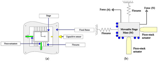
Figure 1.
(a) A schematic diagram of the piezo-driven nanopositioner stage; (b) mechanical model of the piezo-driven nanopositioner.
As shown in Figure 1a, the axis of the piezo-driven stage is equipped with a capacitive sensor for position measurement. The two axes (x and y) are driven by piezo stack flexure-based actuators. Each actuator is capable of generating 40 m of motion along each axis with the aid of flexures.
The dynamic system can be described by the linear differential equation. The equation of motion is formulated using Newton’s law as follows:
The simplified system is characterised by the stiffness and the damping of the flexures, referred to as and , whilst the inertia (mass) of the stage is denoted as . The system dynamics is regulated by the piezo-actuator force that moves the nanopositioning stage and is called , and the stiffness is . The displacement of the stage is referred to as d. As the flexures and the actuators are mechanically parallel, their stiffness can be combined, as in the equation below:
where k denotes the combined stiffness. Therefore, the following transfer function describes the relationship between the applied force of actuator and the displacement of the stage by taking the Laplace transform of Equation (2).
Figure 2a presents a snapshot of the experimental setup, and it consists of a two-axis (x and y) serial kinematic piezoelectric stack-driven flexure-based nanopositioner. Each axis is driven by a 10-mm 200-V piezoelectric stack actuator capable of generating 40 m of motion along each axis. The nanopositioner also provides integrated mounts for capacitive sensor probes. The MicroSense 6810 capacitive displacement sensor and 6504-01 probe with a sensitivity of 5 m/V provide a voltage signal proportional to the displacement sensed along each axis. The piezoelectric stack actuators are driven by two PiezoDrive PDL200 voltage amplifiers with a gain of 20. All the open-loop and closed-loop experiments and consequent time-domain data are captured using a real-time module at a sampling frequency of 20 kHz. The frequency response data are recorded using an HP 35670A FFT Dynamic Signal Analyser (DSA). The open-loop frequency response of one axis of the nanopositioner is obtained by sending a band-limited random noise input generated by the DSA of amplitude 0.25 within the frequency range 20 Hz–2 kHz. This signal was fed to the voltage amplifier as the input, and the output of the amplifier was used to excite the piezoelectric stack. This input corresponds to a displacement within 0 and 2 m, or 5% of the total range of the stage. The open-loop transfer function-based model for the x-axis of the piezo-driven nanopositioner is presented in Figure 2b. The system is characterised by the resulting first dominant resonance of the x-axis, which appears at 716 Hz, as is clear from Figure 2b.
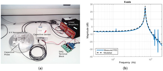
Figure 2.
(a) A two-axis serial-kinematic nanopositioning platform with a range of 40 m driven by two PiezoDrive 200 V linear voltage amplifiers, with position measured by capacitive sensor; (b) comparison of the measured magnitude response of the stage axis (solid blue) and that of the derived second-order model (dashed black).
The resulting mechanical frequency response can be described as in the following dynamic system transfer function using the frequency response analysis:
where is the damping ratio, is the natural frequency, and is chosen to adjust the gain of the stage at 0-Hz frequency. The transfer function of the stage is identified solely based on the first dominant mode, as in the following transfer function:
This is because a simple second-order transfer function with a suitably low damping coefficient and the correct resonant frequency is sufficient to capture the dominant in-bandwidth dynamics of a nanopositioner axis. This model will be used in the design of the controllers in this article. There are a couple of low-magnitude modes seen within the bandwidth of interest, but these are beyond the dominant mode. These can be safely ignored due to their small dynamic range compared to that of the dominant mode at 716 Hz. Consequently, the measured magnitude response looks similar to that exhibited by a typical second-order system with low damping. As the identification was done from 20 Hz onwards, the effect of creep was eliminated due to the absence of any low-frequency components. The piezoelectric stack actuator for the other axis was shorted to eliminate its cross-coupling effect. The sensor and the operational amplifier can be modelled by a first-order low-pass filter with a cut-off frequency of 10,000 Hz and 5000 Hz, respectively. The system identification process for a linear dynamic model of the considered system is thus completed.
In order to allow for an accurate description of the system, this work utilises a nonlinear hysteresis model for the nanopositioner. Bouc–Wen is a popular hysteresis modelling technique to approximate the physical hysteretic behaviour of the system. It uses a first-order nonlinear differential equation with displacement as its input variable and restoring force as its output variable, as shown in Equation (6) [30]:
The applied voltage can be denoted as u and x as the displacement of the piezoelectric actuator; m, b, k and d represent the effective mass, damping coefficient, mechanical stiffness and effective piezoelectric coefficients ( m per volt), respectively. h represents the nonlinear relationship between the lag force (the applied voltage) and the displacement. The parameters , and are identified simultaneously in order to represent the hysteresis loop’s magnitude and shape, where , and , which capture the major hysteresis cycles. The identified Bouc–Wen hysteresis model represents the nonlinear behaviour, and the above equations are realised in MATLAB Simulink, as in the following figure. The proposed hysteresis model is investigated by applying a 180-V peak amplitude sinusoidal signal of 10 Hz to the nanopositioner. A comparison of recorded and simulated displacement profiles is performed in open-loop, as is evident in Figure 3.
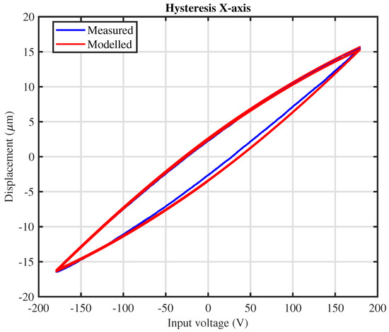
Figure 3.
Measured (blue) and modelled (red) hysteresis loops show that the hysteresis model accurately captures the hysteresis of the piezo-actuators (x-axis).
A nonlinear rate-independent relationship is found to exist between the control voltages applied to the piezo-actuators and their displacements (10 m). From the figure, it can be observed that the output of the nanopositioner is independent of the input. As the sinusoidal input alternates between an increasing and decreasing condition, the output of the nanopositioner diverges from its desired path, resulting in a hysteresis loop. The hysteresis loop is a measure of the deformation of the piezo-driven nanopositioner displacement in response to the sinusoidal input voltage. As mentioned above with regard to precise positioning, this behaviour should be modelled and eliminated. The following section presents the traditional control of the piezo-driven nanopositioner.
3. Control Strategy
This section is divided into two subsections for the sake of clarity. Section 3.1 introduces the traditional control strategy, while Section 3.2 proposes a new control method.
3.1. Traditional Method Using PI with Exact Pole-Zero Cancellation
The traditional method using a PI controller is based on exact cancellation of the IRC pole, as reported in [29]. Consider the traditional control strategy in Figure 4, where r is the reference, y is the output and D is disturbance.
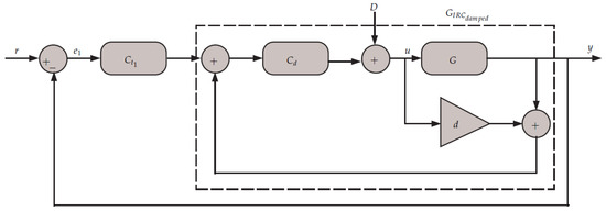
Figure 4.
Block diagrams for the traditional control scheme.
The characteristics equation of the damped system can be determined using the following equation, where the value of the damping ratio () is 0.0102, and the natural frequency (), where the value of the is and is :
where:
where is the damping gain, d is the feed-through term and G is the plant; therefore, the characteristic equation of the damped system is given by:
The value of the maximum damping gain can be obtained using the following formula, as reported in [31]:
In order to ensure stability, the following quantity must be obeyed:
The PI tracking controller is given by:
where is the integral tracking gain and is the zero of the PI. The system has complex conjugate pair poles, plus a pole on the x-axis (real pole introduced by the IRC). The solution to the characteristics equation in (8) would provide the frequency of the additional pole, which is the real value root of Equation (8). The frequency can be determined, as in the following formula, using Cardano’s method [32]:
where:
The traditional PI controller has a real pole at zero frequency and zero at frequency. In order to cancel exactly the IRC pole with the zero introduced by the PI, . The design method is based on selecting the maximum damping gain for the IRC. The value of the feed-through term d is chosen to produce a pair of zeros below the first resonant mode. The frequency of the zero of the PI controller () is chosen in such away as to cancel exactly the pole introduced by the IRC (same frequency). As for the value of the integral gain, is selected to maintain a sufficient gain margin. The PI controller using this method has a limited bandwidth, as will become clear later in this paper.
3.2. Proposed Method Using PI with Strategic Zero Placement
This subsection presents the strategic placement to negate the IRC pole and enhance the bandwidth using trial and error. Referring to Figure 4, the overall transfer function of the system can now be determined as follows:
where:
where is the tracking controller, is the integral tracking gain and is the zero of the PI. is the value of the damping gain, and d is the feed-through term. The plant is given by G, as r is the reference and y the output (displacement). Similar to the traditional method in Figure 4, the characteristic equation of the proposed PI controller is given by:
Using experimental validations to confirm the feasibility of the proposed method, it is shown that significant improvement regarding bandwidth and disturbance rejection are reported. To ensure the fairness of comparison, the values of the damping gain and the feed-through term remain the same as in the traditional method using the proposed control strategy. The designed method is based on the frequency response. The following section provides experimental-based optimal values of and such that the closed-loop is stable and maximum bandwidth is achieved.
4. Experimental Results
In this section, experimental-based tuning values for the tracking gain and placement of the PI zero are proposed. The pole-zero maps of the traditional and proposed control methods are plotted in Figure 5. The closed-loop was asymptotically stable using both the conventional and proposed methods. The pole of the IRC was precisely cancelled by the tracking controller using the traditional method, as is clear from Figure 5. Using the proposed method, the pole of the tracking controller was placed at a significant distance from the IRC pole in accordance with the best achievable bandwidth, as in Figure 6. From the figure, it can be observed that placing the PI zero at a significant distance from the IRC pole was important for increasing the bandwidth. It should be noted that, in order to guarantee stability, it is recommended that 10,000 for the selected value of , as in Table 1. With regard to the value of the integral gain, is selected to provide a sufficient phase margin for the system to account for time delay and provide a reasonable gain margin for uncertainties. Table 1 lists the controller parameters obtained experimentally for both the traditional and the proposed method. The table shows that the arrangement of the PI zero in such a way as to cancel exactly the IRC pole ( ) is not beneficial.
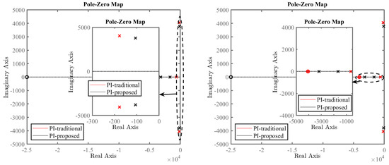
Figure 5.
Comparison of the pole and zero locations for the traditional and the proposed control methods. Insets show zoomed-in areas for clarity.
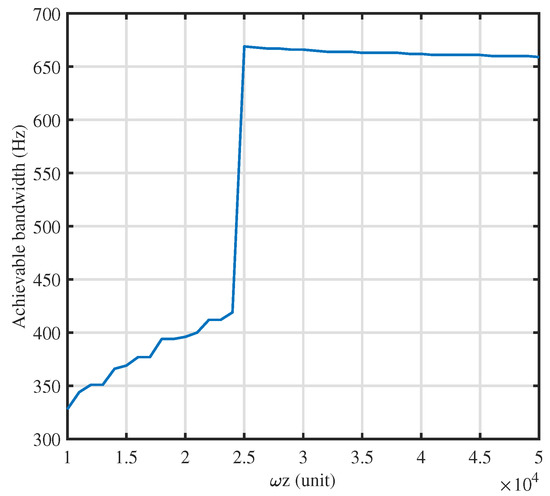
Figure 6.
Selective zero placement for maximum bandwidth.

Table 1.
The controller parameters of PI using the traditional and proposed method.
Using the traditional method for the selected value of = , in order to guarantee stability and provide a reasonable stability margin, the value of the tracking gain was chosen to be around 1300. Thus, the maximum allowable value of the tracking gain was 1300. As shown in Table 1, the achievable bandwidth using the traditional method was limited to around 110 Hz. As mentioned above, the selected value of the PI zero to cancel exactly the pole of the IRC restricted the gain margin. On the other hand, placing the PI zero at a significant distance from the IRC pole increased the gain margin, and as a result, a higher value of the tracking gain can be chosen. Therefore, improvement in positioning bandwidth was obtained around 668 Hz, as is clear in Table 1. The table presents the achievable bandwidth such that the closed-loop response must not deviate from ±3 dB. Error was reduced using the proposed method as a result of the higher bandwidth obtained.
Figure 7 shows the open- and closed-loop frequency response obtained experimentally for the traditional and proposed methods. It can be observed that significant improvement in the closed-loop bandwidth was achieved. This improvement was so effective at capturing the frequencies that it formed the triangular wave.
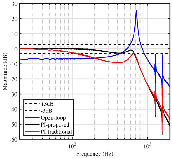
Figure 7.
Frequency response of the system measured experimentally for the x-axis in the open-loop versus the closed-loop.
In order to inspect the obtained bandwidth in the time-domain and in the presence of disturbances such as hysteresis, the time-domain tracking is plotted in Figure 8 for a 20-Hz triangular reference. It can be seen that a significant improvement in tracking performance was achieved using the proposed method.
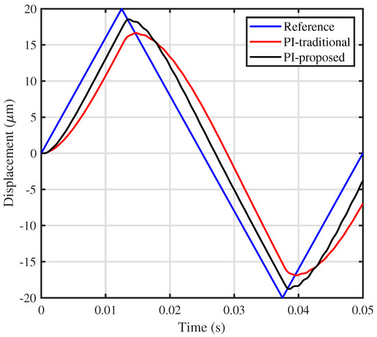
Figure 8.
Time-domain tracking performance using the traditional and proposed method.
In order to further show the significant improvement, Figure 9 provides the root mean squared error (RMSE) for tracking triangular trajectories. The error was reduced remarkably using the proposed method.
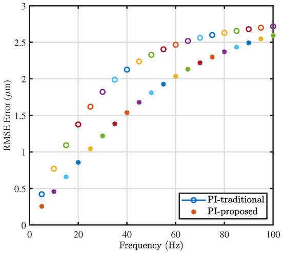
Figure 9.
Comparison of the RMSE for triangular trajectories with different fundamental frequencies.
In order to account for uncertainties, such as unmodelled dynamics and latency due to amplifier and sensor circuitry, the tuned controller parameters offered a reasonably stable system. The experimental results provided a sufficient phase margin to account for time delay in the system and GM to account for uncertainties. The greater the stability margins, the more stable the system in the closed-loop. The nanopositioning stage was susceptible to parameter changes due to loading, and therefore, sufficient GM can cope with the loading condition.
The disturbance rejection profile of the proposed method can be obtained by substituting r = 0 in Figure 4 and calculating D, as in Equation (15):
The above transfer function was tested experimentally and is plotted in Figure 10a,b.
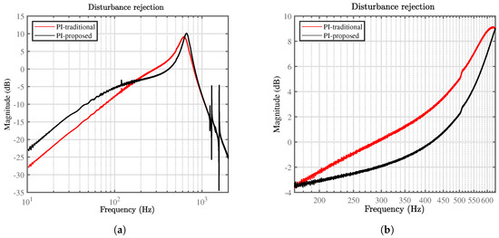
Figure 10.
Disturbance rejection profile for the proposed and traditional method: (a) over the entire bandwidth; (b) over the bandwidth of interest.
Significant disturbance rejection was provided over the bandwidth of interest. The capability of the traditional control method was minimal within the bandwidth of interest, while the proposed method offered higher disturbance. It should be noted that the disturbance profile of the proposed method was minimal around the resonant.
5. Conclusions
This article presents a novel PI tracking control method via strategic zero placement to improve the positioning bandwidth of the nanopositioners. The ability of the proposed controller to withstand disturbance is tested experimentally. The proposed method offers better rejection within the bandwidth of interest than the traditional method. The tracking performance of the proposed controller is tested for various triangular trajectories, and less error is generated in comparison to the traditional method.
Author Contributions
M.A. is the lead author, who developed most of the theory and wrote the article. S.A. provided technical guidance during simulations and experiments, as well as during the writing of the paper and its revision.
Funding
This research received no external funding.
Conflicts of Interest
The authors declare no conflict of interest.
References
- Shieh, H.J.; Lin, F.J.; Huang, P.K.; Teng, L.T. Adaptive displacement control with hysteresis modelling for piezoactuated positioning mechanism. IEEE Trans. Ind. Electron. 2006, 53, 905–914. [Google Scholar] [CrossRef]
- Li, Y.; Xu, Q. A novel piezoactuated XY stage with parallel, decoupled, and stacked flexure structure for micro-/nanopositioning. IEEE Trans. Ind. Electron. 2011, 58, 3601–3615. [Google Scholar] [CrossRef]
- Salapaka, S.; Sebastian, A.; Cleveland, J.P.; Salapaka, M.V. High bandwidth nano-positioner: A robust control approach. Rev. Sci. Instrum. 2002, 73, 3232–3241. [Google Scholar] [CrossRef]
- Xu, Q. New flexure parallel-kinematic micropositioning system with large workspace. IEEE Trans. Robot. 2012, 28, 478–491. [Google Scholar] [CrossRef]
- Wu, Z.; Xu, Q. Design, optimization and testing of a compact XY parallel nanopositioning stage with stacked structure. Mech. Mach. Theory 2018, 126, 171–188. [Google Scholar] [CrossRef]
- Krohs, F.; Onal, C.; Sitti, M.; Fatikow, S. Towards automated nanoassembly with the atomic force microscope: A versatile drift compensation procedure. J. Dyn. Syst. Meas. Control 2009, 131, 061106. [Google Scholar] [CrossRef]
- Eielsen, A.A. Topics in Control of Nanopositioning Devices. Ph.D. Thesis, Norges Teknisk-Naturvitenskapelige Universitet, Trondhiem, Norway, 2012. [Google Scholar]
- Russell, D.; San-Millan, A.; Feliu, V.; Aphale, S.S. Butterworth Pattern-based Simultaneous Damping and Tracking Controller Designs for Nanopositioning Systems. Front. Mech. Eng. 2016, 2, 2. [Google Scholar] [CrossRef]
- Preumont, A. Vibration Control of Active Structures, 3rd ed.; Springer: Berlin, Germnay, 2011; Volume 2. [Google Scholar]
- Croft, D.; Devasia, S. Hysteresis and vibration compensation for piezoactuators. J. Guid. Control Dyn. 1998, 21, 710–717. [Google Scholar] [CrossRef]
- Fleming, A.J. Nanopositioning system with force feedback for high-performance tracking and vibration control. IEEE/ASME Trans. Mechatron. 2010, 15, 433–447. [Google Scholar] [CrossRef]
- Rana, M.; Pota, H.R.; Petersen, I.R. A Survey of Methods Used to Control Piezoelectric Tube Scanners in High-Speed AFM Imaging. Asian J. Control 2018. [Google Scholar] [CrossRef]
- Yong, Y.K.; Liu, K.; Moheimani, S.R. Reducing cross-coupling in a compliant XY nanopositioner for fast and accurate raster scanning. IEEE Trans. Control Syst. Technol. 2010, 18, 1172–1179. [Google Scholar] [CrossRef]
- Zareinejad, M.; Ghidary, S.S.; Rezaei, S.M.; Abdullah, A. Precision control of a piezo-actuated micro telemanipulation system. Int. J. Precis. Eng. Manuf. 2010, 11, 55–65. [Google Scholar] [CrossRef]
- Alunda, B.O.; Lee, Y.J.; Park, S. Comparative study of two types of parallel kinematic flexure scanners for atomic force microscopy. Instrum. Sci. Technol. 2018, 46, 58–75. [Google Scholar] [CrossRef]
- Wolf, F.; Sutor, A.; Rupitsch, S.J.; Lerch, R. Modeling and measurement of creep-and rate-dependent hysteresis in ferroelectric actuators. Sens. Actuators A Phys. 2011, 172, 245–252. [Google Scholar] [CrossRef]
- Russell, D.; Fleming, A.J.; Aphale, S.S. Simultaneous optimization of damping and tracking controller parameters via selective pole placement for enhanced positioning bandwidth of nanopositioners. J. Dyn. Syst. Meas. Control 2015, 137, 101004. [Google Scholar] [CrossRef]
- Aphale, S.S.; Devasia, S.; Moheimani, S.R. High-bandwidth control of a piezoelectric nanopositioning stage in the presence of plant uncertainties. Nanotechnology 2008, 19, 125503. [Google Scholar] [CrossRef] [PubMed]
- Fleming, A.J.; Leang, K.K. Design, Modeling and Control of Nanopositioning Systems; Springer: Berlin, Germany, 2014. [Google Scholar]
- Teo, Y.R.; Russell, D.; Aphale, S.S.; Fleming, A.J. Optimal integral force feedback and structured pi tracking control: Application for objective lens positioner. Mechatronics 2014, 24, 701–711. [Google Scholar] [CrossRef]
- Aphale, S.S.; Fleming, A.J.; Moheimani, S.R. Integral resonant control of collocated smart structures. Smart Mater. Struct. 2007, 16, 439. [Google Scholar] [CrossRef]
- Bhikkaji, B.; Ratnam, M.; Moheimani, S.R. PVPF control of piezoelectric tube scanners. Sens. Actuators A Phys. 2007, 135, 700–712. [Google Scholar] [CrossRef]
- Hagood, N.W.; von Flotow, A. Damping of structural vibrations with piezoelectric materials and passive electrical networks. J. Sound Vib. 1991, 146, 243–268. [Google Scholar] [CrossRef]
- Sebastian, A.; Salapaka, S.M. Design methodologies for robust nano-positioning. IEEE Trans. Control Syst. Technol. 2005, 13, 868–876. [Google Scholar] [CrossRef]
- Marinangeli, L.; Alijani, F.; HosseinNia, S.H. Fractional-order positive position feedback compensator for active vibration control of a smart composite plate. J. Sound Vib. 2018, 412, 1–16. [Google Scholar] [CrossRef]
- Sebastian, A.; Pantazi, A.; Moheimani, S.R.; Pozidis, H.; Eleftheriou, E. Achieving subnanometer precision in a MEMS-based storage device during self-servo write process. IEEE Trans. Nanotechnol. 2008, 7, 586–595. [Google Scholar] [CrossRef]
- Altaher, M.; Aphale, S.S. High-Precision Control of a Piezo-Driven Nanopositioner Using Fuzzy Logic Controllers. Computers 2018, 7, 10. [Google Scholar] [CrossRef]
- Altaher, M.; Russell, D.; Aphale, S.S. A dual-loop tracking control approach to precise nanopositioning. J. Vib. Control 2018. [Google Scholar] [CrossRef]
- Fleming, A.J.; Teo, Y.R.; Leang, K.K. Low-order damping and tracking control for scanning probe systems. Front. Mech. Eng. 2015, 1, 14. [Google Scholar] [CrossRef]
- Weber, F. Bouc–Wen model-based real-time force tracking scheme for MR dampers. Smart Mater. Struct. 2013, 22, 045012. [Google Scholar] [CrossRef]
- Namavar, M.; Fleming, A.J.; Aleyaasin, M.; Nakkeeran, K.; Aphale, S.S. An analytical approach to integral resonant control of second-order systems. IEEE/ASME Trans. Mechatron. 2014, 19, 651–659. [Google Scholar] [CrossRef]
- Press, W.H.; Teukolsky, S.A.; Vetterling, W.T.; Flannery, B.P. Numerical Recipes 3rd Edition: The Art of Scientific Computing; Cambridge University Press: Cambridge, UK, 2007. [Google Scholar]


© 2019 by the authors. Licensee MDPI, Basel, Switzerland. This article is an open access article distributed under the terms and conditions of the Creative Commons Attribution (CC BY) license (http://creativecommons.org/licenses/by/4.0/).