Article

Effectiveness of Surface Pre-Application of Compressed Air Foam in Delaying Combustion Spread to Adjacent Buildings

National Fire Research Institute, 376, Songak-ro, Songak-myeon, Asan-si 31555, Republic of Korea
*
Author to whom correspondence should be addressed.
Fire 2025, 8(9), 359; https://doi.org/10.3390/fire8090359
Submission received: 14 July 2025 / Revised: 28 August 2025 / Accepted: 5 September 2025 / Published: 8 September 2025

Abstract

Sandwich panels, widely used in factory and warehouse construction, are highly susceptible to fire due to their fragile surfaces and polyurethane-insulated cores. Such structures facilitate rapid fire spread, significantly increasing the risk of extensive thermal damage. Although conventional measures, such as surface pre-wetting, are commonly utilized, their effectiveness is limited due to rapid evaporation. To address this issue, the current study evaluates the effectiveness of compressed air foam (CAF) applied as a pre-application treatment for delaying fire spread. Full-scale fire experiments were conducted to measure temperature variations across sandwich panel surfaces treated under three different conditions: untreated, water-treated, and CAF-treated. Experimental results indicated that CAF effectively formed a stable insulating barrier, maintaining temperatures well below critical thresholds, compared to untreated and water-treated panels. CAF application demonstrated superior thermal protection, reducing internal temperatures by up to 78% compared to untreated conditions and by 67.5% compared to water-treated conditions. These findings underscore the practical importance of adopting CAF pre-application as a proactive fire mitigation strategy, significantly enhancing fire safety standards in industrial and storage facilities constructed with sandwich panels.

1. Introduction

Sandwich panels are widely used in factories and warehouse complexes due to their simplicity and seamless construction. However, their urethane-insulated core and relatively weak surface make them vulnerable to fire. Once the insulation reaches its melting point, toxic gases are released, and air infiltration through panel joints accelerates combustion, leading to rapid fire growth. The steel facings further transmit heat owing to their high thermal conductivity of approximately 50 W/m·K [1,2], which accelerates heat transfer into the core and promotes the thermal degradation of the insulation. At elevated temperatures, the material weakens and deforms, hindering firefighting efforts and increasing casualty risks [3].
Globally, the dangers of flammable substances have been acknowledged, and research efforts are ongoing to implement safety measures. The National Fire Protection Association (NFPA) published a research report on warehouse fires titled, ‘Structure Fires in Warehouse Properties’ [4]. The report determines the number of fires that occur each year and the extent of the damage caused. The Confederation of National Fire Protection Organizations in Europe (CFPA EUROPE) presents guidelines for fire prevention and protection measures based on the European Guidelines on Fire Safety in Warehouses [5]. The use of combustible materials (such as urethane foam, aluminum composite materials, and plastic) as exterior materials was prohibited in the United Kingdom in October 2018 following the 2017 Grenfell Tower fire [6]. In industrial facilities and warehouse complexes, where buildings are closely located and contain various flammable materials, the construction of buildings using sandwich panels remains a prevalent practice. However, in the event of a fire in such structures, it may rapidly reach its peak and spread to adjacent buildings. Utilizing sandwich panels in the structural composition, in conjunction with a steel frame, exacerbates the probability of collapse. Therefore, comprehensive measures and rapid response protocols are required for areas with sandwich panel buildings.
In general, when a fire breaks out in a factory or warehouse complex constructed using sandwich panels, the fire is extinguished using water. Water-based fire extinguishing is the simplest and most commonly used method and is one of the most representative fire extinguishing methods [7]. Water, an easily available, economical, and environmentally friendly fire extinguishing agent [8], has high latent heat owing to its thermal properties, enabling it to effectively absorb heat during a fire.
In contrast, factories and warehouse complexes with a high density of sandwich structures are prone to rapid fire spread, making it necessary to extinguish the fire directly at the site of the fire and prevent it from spreading to adjacent buildings. Kwon et al. [9] demonstrated that the preliminary water supply of a building composed of lightweight steel and sandwich panels can effectively delay the ignition time and reduce the temperature. However, as the amount of water that can be used by fire engines is limited, it is necessary to develop a more effective preliminary water supply to the surface of adjacent buildings where fires have occurred.
Kim et al. [10] studied the thermal properties of extinguishing agents and reported that foam extinguishing agents can effectively extinguish fires. Firefighting foam is a chemical substance with improved permeability owing to its lower surface tension than water. It better penetrates materials such as fibers and fabrics and has a larger surface area in contact with the fuel, resulting in a higher heat absorption rate [11]. The foam adheres to the surface of hot combustible materials and extinguishes the material via oxygen suffocation and cooling. It interferes with the binding of oxygen and combustible vapors and prevents the chemical chain reaction that causes the release of steam and the resultant combustion of the material. The oxygen-blocking capability of the foam is a different extinguishing mechanism used to extinguish fires. The foam breaks when exposed to an external heat flow, and the liquid evaporates from the surface of the foam. This causes the microstructure of the foam to adjust and the foaming solution to flow [12]. Foam exerts a side cooling effect through moisture. Water diffuses heat through vaporization, whereas foam absorbs the heat diffused through vaporization [13].
Recently, fire trucks equipped with compressed air foam systems (CAFSs) have been increasingly dispatched to fire scenes. A CAFS combines a foam solution with compressed air to produce millions of microscopic bubbles. Conventional foam systems use an air-aspiration discharge device to draw in air and combine it with the foam solution to produce foam [14]. A CAF is created by injecting compressed air bubbles into the foaming solution in the mixing chamber, creating complete turbulence between the gas and the liquid, unlike conventional foaming systems [15]. In particular, because many of the bubbles in CAF are surrounded by a thin film, they absorb more heat than the same volume of water [16]. The fire-extinguishing capability of CAF was evaluated in Class A fires and compared with water. A comparison of the effectiveness of water and CAF in extinguishing Class A fires showed that CAF reduced the temperature 75–85% faster than water and reduced combustion products 78% faster [17]. According to the results of a study on the fire combustion characteristics of CAF and the effectiveness of each fire extinguishing agent, CAF outperformed conventional foam fire extinguishing agents [18]. In addition, a comparative study of the fire suppression performance of fire extinguishing agents in compartment fires revealed that the fire extinguishing ability of CAF is superior to that of pure water and traditional foam [19,20]. Madrzykowski [21] studied the thermal properties of CAF by conducting ignition delay and mass retention tests. When the CAF was coated on vertical plywood and radiant heat was applied to the specimen, the foam-coated plywood had twice the ignition delay time of the water-coated plywood.
Previous studies have predominantly investigated the thermal blocking effects of water or conventional firefighting foams under small-scale experimental conditions. However, there is a noticeable lack of research analyzing the effectiveness of pre-applied compressed air foam (CAF) on large-scale structural surfaces under realistic fire scenarios. In particular, empirical evidence demonstrating CAF’s effectiveness in delaying fire spread to adjacent buildings under full-scale conditions remains limited.
Therefore, this study aims to experimentally verify the effectiveness of pre-application with water and CAF on the surfaces of full-scale sandwich panel structures in delaying heat transfer and fire spread to neighboring buildings. By conducting full-scale fire experiments under realistic conditions, this research addresses the limitations of prior small-scale studies and proposes a more practical and proactive firefighting strategy applicable to actual fire suppression scenarios.

2. Experimental Methods

2.1. Experimental Structure

2.1.1. Pre-Experiments Structure

A sandwich panel structure was constructed to scale down the building to establish experimental conditions. The effectiveness of the agent was examined to determine reasonable test conditions based on the scaled-down experiment before performing a real fire experiment based on a structure composed of real sandwich panels.
The distance between the sandwich panel and the ignition source was 1.0 m, which was determined in accordance with Article 242 of the Civil Act in Korea (construction near the boundary line) [22]. The ignition source (sand burner) was positioned 1 m from each panel to ensure that the sandwich panels, installed in a “⊓” shape to minimize wind effects, were exposed to a constant radiant heat source, as shown in Figure 1a,b. K-type thermocouples were positioned at varying heights (0.6, 1.0, and 1.4 m) along the central axis of the sandwich panel, on the surface, and within the core to ascertain the temperature as shown in Figure 1c.

2.1.2. Main Experiments Structure

The experimental design and procedures were established with reference to the SFPE Handbook of Fire Protection Engineering (5th edition) and ISO 13784-1: Reaction-to-fire tests for sandwich panel building systems [23]. These standards were used to define the ignition heat flux, measurement locations, and evaluation criteria, thereby ensuring that the test conditions were consistent with internationally recognized fire testing practices.
A full-scale fire experiment was conducted in a building with a composition similar to that of an actual sandwich structure. The experiment was conducted in an outdoor setting. A shield comprising panels and a gypsum board was constructed to mitigate the impact of external environmental factors, such as wind, as illustrated in Figure 2. Water and CAFS were applied using a fire truck equipped with CAFS from a nearby fire station.
The air-to-solution ratio for CAF was set to 1:14, and the foam was used in a dry state to enhance surface adhesion when utilizing CAFS. This ratio was selected based on previous research indicating that an air-to-solution ratio of approximately 1:13 provides optimal performance in Class A fire scenarios [24]. Therefore, a comparable ratio of 1:14 was applied in this study to reflect effective operating conditions for CAF. Other expansion ratios (e.g., 5 or 10) were not tested, and this limitation has been explicitly acknowledged for future work.
A Class A foam concentrate was used to produce CAF, mixed with water and compressed air through the CAFS. Typical properties of Class A foam solutions reported in the literature include a surface tension of approximately 28–30 mN/m and a kinematic viscosity of ~1.2 mm2/s, which are consistent with the values observed for the concentrate used in this study [25,26].
The foam layer thickness was not strictly controlled during application, but visual measurements indicated an average thickness of approximately 3–5 mm across the treated surfaces. While this range was sufficient to maintain surface coverage during the experiment, variations in layer thickness may influence fire-resistance performance. This limitation has been noted, and future studies will systematically control and evaluate CAF layer thickness.
The average application density of CAF on the sandwich panel surfaces was approximately 20 L/m2, which ensured full surface coverage during the pre-application. Some foam drainage and minor loss occurred due to gravity; however, the coverage remained sufficient to maintain a continuous insulating layer throughout the exposure period. In contrast, the water pre-wetting condition required the same volumetric application but did not retain a stable layer on the vertical surfaces, as the water rapidly drained off. This difference in retention highlights the superior surface adhesion and quality of the foam layer compared to water application
The sandwich panel assembly used in the test reflected typical factory construction practices, consisting of 0.5 mm thick galvanized steel facings and 100 mm thick expanded polystyrene (EPS) insulation. This ensured that the test structure was representative of actual building configurations commonly found in industrial settings.
In this study, the “connection” refers to the junctions between adjacent sandwich panels rather than separate metallic connectors. These connection areas consisted of the same galvanized steel facings (0.5 mm thick, thermal conductivity ~50 W/m·K) and EPS insulation (melting point ~70 °C) as the rest of the panels, but the structural gaps made them more vulnerable to flame penetration.
In a sandwich panel structure, fire spread throughout the structure is primarily facilitated by gaps in the connections between the panels created by the melting of interior materials. The temperature of the sandwich panel center and that of the joint were examined. Thermocouples were installed at varying heights (0.6, 1.0, 1.4, and 1.8 m) on the exterior surface of the structure and at depths within the panel to ascertain the temperature changes occurring within the structure, as shown in Figure 3. K-type thermocouples were utilized, with the precise installation location illustrated in Figure 4. A scaled-down model of the Class-A combustion model was developed to create an ignition source.
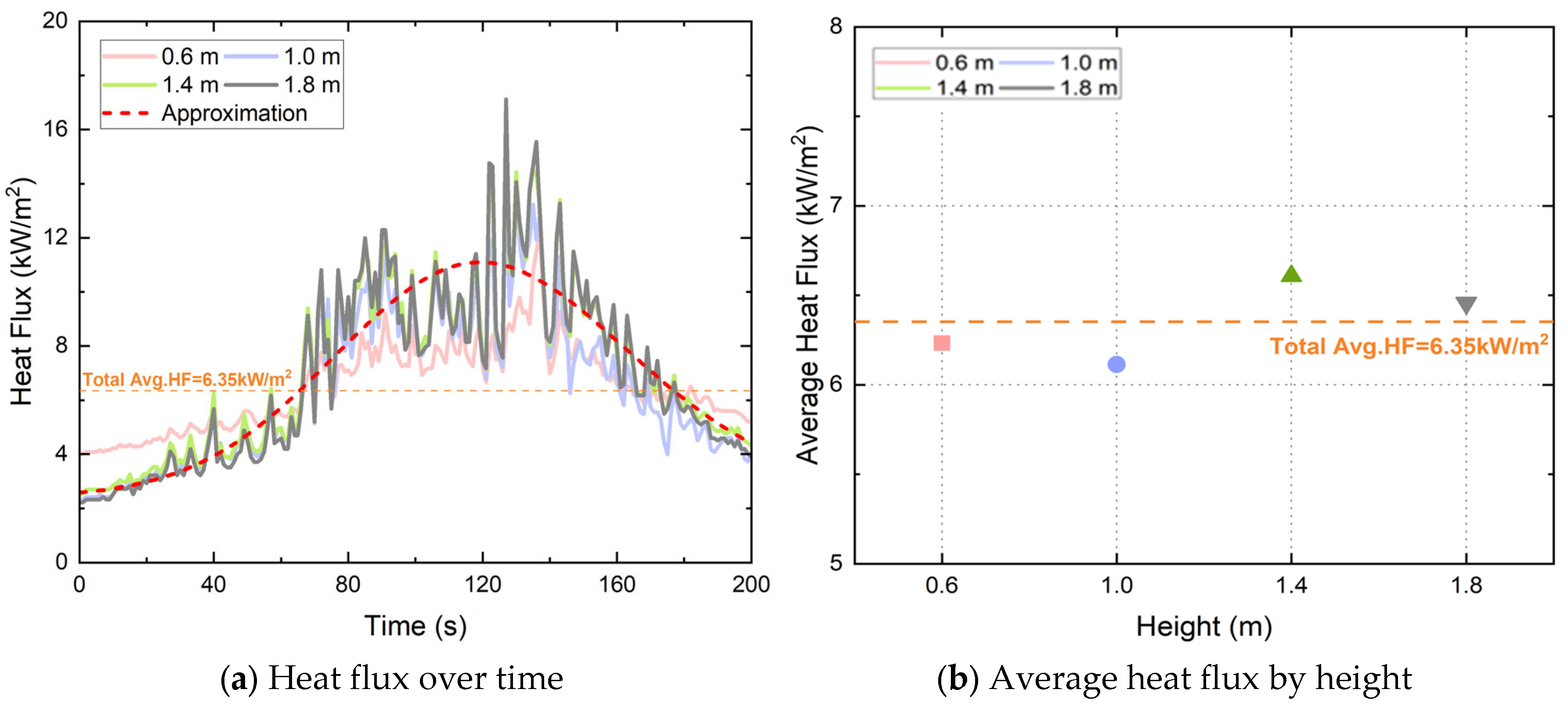
Referring to the American SFPE Handbook of Fire Protection Engineering [27], the maximum radiant heat flux of the ignition source was set to the standard value of 12.5–25.0 kW/m2, which can affect the equipment (Table 1). To this end, the heat flux was measured from ignition (0 s) to 200 s, and the average heat flux value for each height over the entire section was confirmed to be approximately 6.35 kW/m2. However, the value includes both the rising and falling sections, and when analyzing the maximum radiant heat flux value by height, it was set to have an average maximum radiant heat flux value of 15.2 kW/m2, with a minimum of 12.1 kW/m2 and a maximum of 17.1 kW/m2 (Figure 5).

2.2. Experimental Procedure

2.2.1. Pre-Experiments Procedure

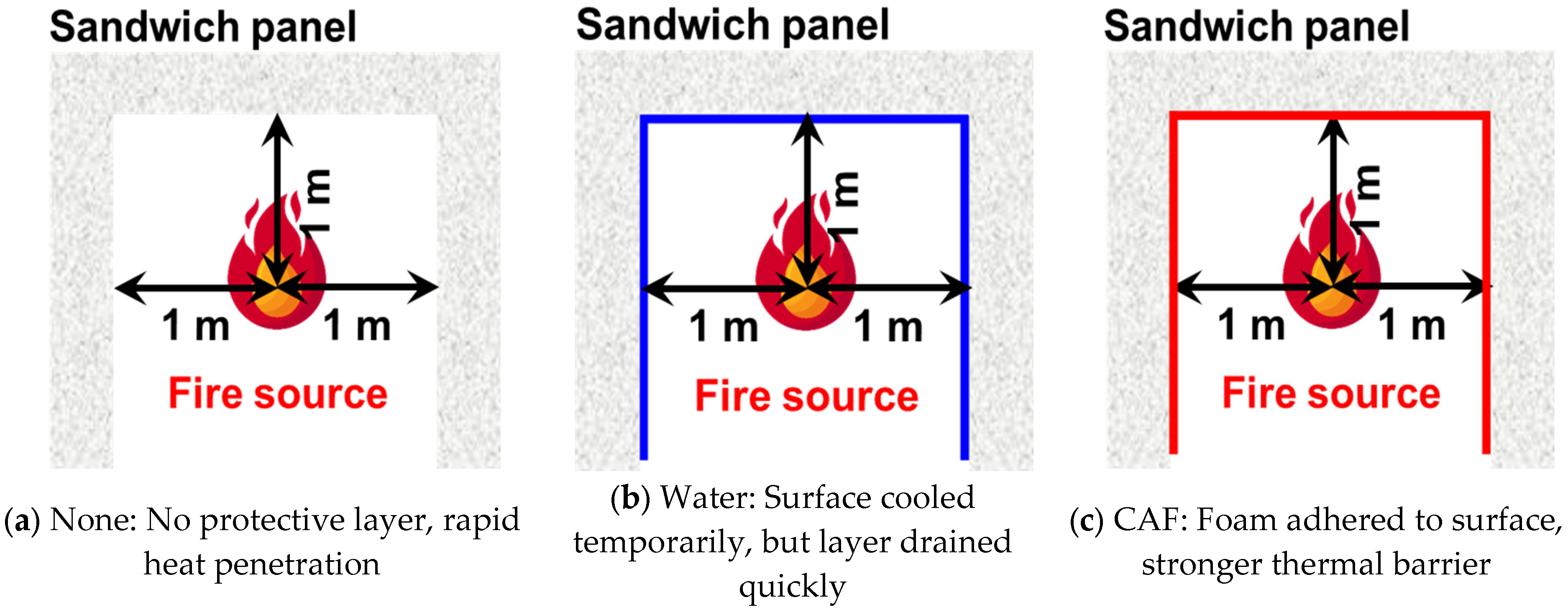
Figure 6 illustrates the preliminary experiment procedure. First, the sandwich panel was positioned in the shape of the symbol “⊓.” Before igniting the ignition source, the surface of the sandwich panel can be described as comprising three crucial conditions (Figure 7):
  • Nothing pre-application at the surface: none.
  • Water pre-application at the surface: water.
  • Compressed air foam pre-application at surface: CAF.
The temperature change in the surface and core of the sandwich panel under each condition was observed following the ignition of the ignition source. The test duration was 800 s, and 600 s was allowed for the pre-applied water or agent to evaporate from the surface.

2.2.2. Main Experiments Procedure

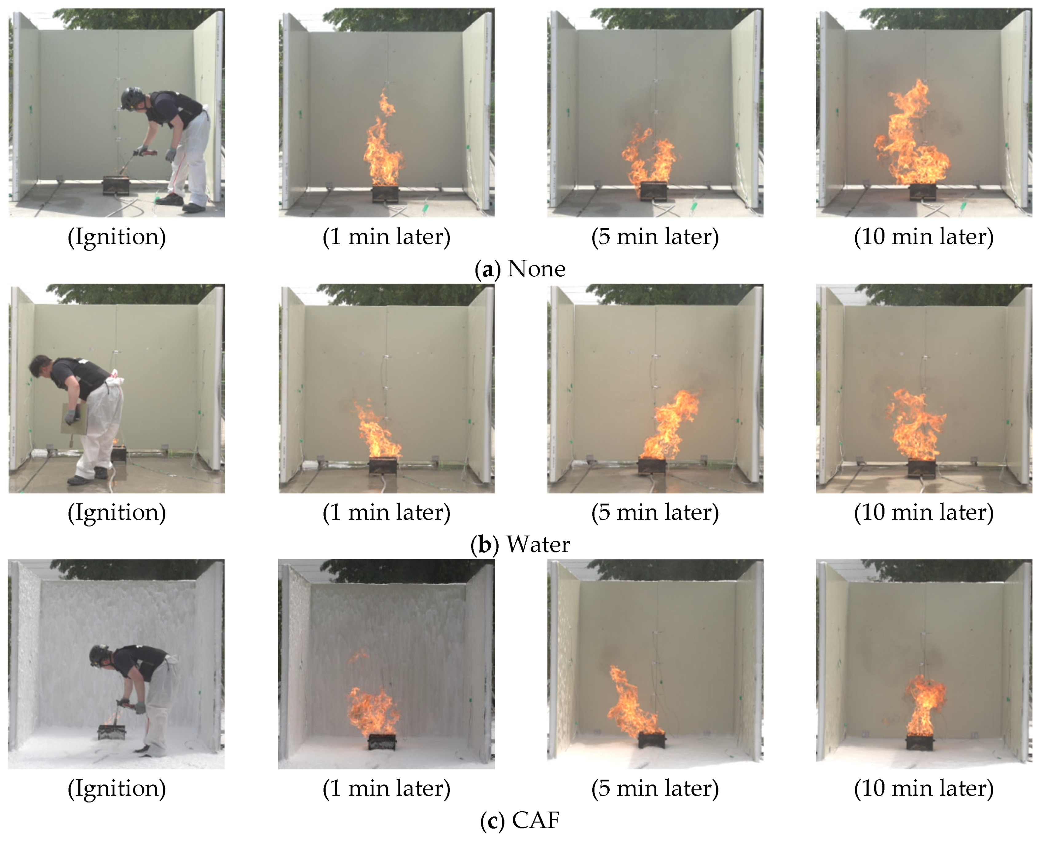
Before source ignition, the surface of the sandwich panel structure was prepared in accordance with one of the following three conditions: untreated, water-treated, and compressed air foam-treated. As shown in Figure 8, the untreated surface was called “None,” the water-treated surface was referred to as “Water,” and “CAF” indicated the pre-application surface by compressed air foam. Subsequently, the ignition source was ignited and the surface temperature was monitored. The experiment was conducted for 300 s, beginning with the ignition of the ignition source (0 s). In the event of a fire spreading to the sandwich panel, a forced extinguishment procedure was initiated to ensure safety. The experiment was repeated twice under identical conditions, and the mean of the two measurements was used to negate the impact of external factors on the results.

2.2.3. Limitations

Due to the high cost and logistical constraints of full-scale fire testing, the number of experimental repetitions was limited to two. As a result, statistical analyses such as standard deviations and hypothesis testing (e.g., t-tests or ANOVA) could not be conducted with sufficient power. This limitation has been explicitly acknowledged in the present study, and future studies should increase the number of replicates (e.g., n ≥ 5) to strengthen statistical validity and enable more robust quantitative conclusions.
Furthermore, although the observed variation between replicates was within ±5 °C, the limited number of samples prevented the use of statistical tests to confirm the significance of the differences in heat blocking rates. Future studies should therefore include a larger sample size and apply appropriate statistical analyses to ensure rigorous evaluation of significance.
In addition, environmental factors such as wind speed, humidity, and extended exposure durations were not varied in this study but are recognized as critical for real-world application. Future work will systematically analyze the effects of environmental conditions and different air-to-solution ratios of CAF to enhance external validity.
Furthermore, the stability of CAF under varying environmental conditions such as wind, rainfall, and humidity was not systematically investigated in this study. Previous research has indicated that environmental factors can significantly influence foam durability and heat insulation performance [28]. Future full-scale studies should therefore examine CAF stability under diverse weather conditions to ensure its practical applicability in real fire scenarios.
In addition, only a single expansion ratio (1:14) was tested in this study. Although this value was chosen based on previous research indicating that approximately 1:13 is optimal for Class A fire conditions, it is recognized that actual fire suppression scenarios often involve lower expansion ratios (e.g., 5–10). The absence of comparative experiments across multiple expansion ratios (0, 5, 10, and 14) represents another limitation of this work, and future studies will systematically examine the influence of varying expansion ratios on CAF performance.

3. Results

This study evaluated the influence of external fire on sandwich panels by comparing temperature increases at the surface, core, and compartment under three conditions: untreated (“None”), water pre-application (“Water”), and CAF pre-application (“CAF”).

3.1. Pre-Experiments Results

The preliminary results were analyzed by comparing the surface and core temperatures as shown in Figure 9. First, the average temperatures of water and CAF applied to the sandwich panel surface were examined for 600 s, the estimated time required for the agent to evaporate. A maximum temperature difference of 23.4 °C was observed on the surface for “Water” compared to the case of “None.” The “CAF” yielded a maximum temperature difference of 24.5 °C compared to “None.” However, a maximum temperature difference of 6.8 °C was observed between “Water” and “CAF.” Therefore, the pre-application of water to the surface of the sandwich panel structure in the vicinity of the fire can enhance the efficacy of thermal insulation within the structure by up to 33.9% without water and 38.1% with water, as indicated in Table 2. For each condition, two replicates were conducted, and the results showed consistent trends within a variation of approximately ±5 °C. Due to the small sample size (n = 2), statistical significance testing (e.g., t-tests or ANOVA) could not be performed with sufficient power. Instead, the mean values are presented together with the observed variation, which remained within a narrow range, thereby supporting the reliability of the reported heat blocking rates. However, the insulation material (Styrofoam) utilized for the internal insulation of sandwich panels had a melting point of 70 °C. Consequently, the insulation material melted when the internal temperature exceeded 70 °C owing to an external fire, facilitating the spread of the fire within the structure [23]. The average core temperature was 8.1 °C lower in the “Water” condition than that in “None.” However, the core temperature exceeded 70 °C, the inner material melting point, except for the measurement obtained at a height of 1.4 m, as shown in Figure 9. The surface application of the CAF resulted in a temperature reduction of up to 19.3 °C relative to the “None” condition and 14.7 °C relative to the “Water” application case. However, in particular circumstances, the melting point of the internal materials exceeded 70 °C despite a relatively modest temperature increase. The heat blocking rate of the thermal barrier to the core reached 34.9% and 28.8% in “None” and “Water” conditions, respectively, demonstrating the effectiveness of the thermal barrier to the core. The impact of elevated temperatures was examined to determine the viability of evacuating the occupants to minimize potential damage to the vicinity structures. The temperature increase was delayed at all heights as follows: CAF > Water > None.

3.2. Main Experiments Results

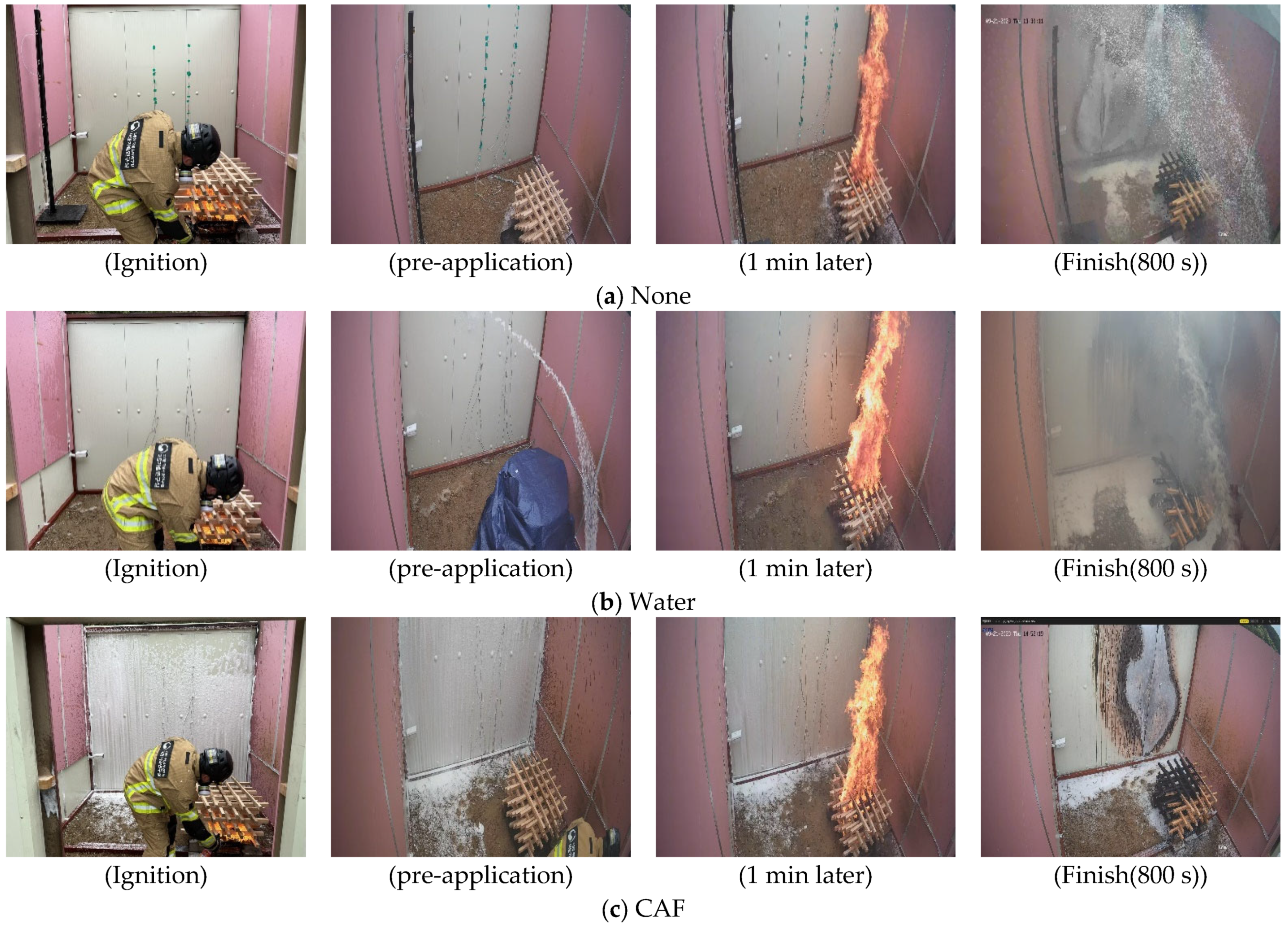
The test was conducted in a shielded room with a Class A model ignited and observed until spontaneous extinction. In the event of a direct flame contact with the sandwich panel, the test was terminated by forced extinction. Figure 10 illustrates the detailed procedure.

3.2.1. Surface Temperature

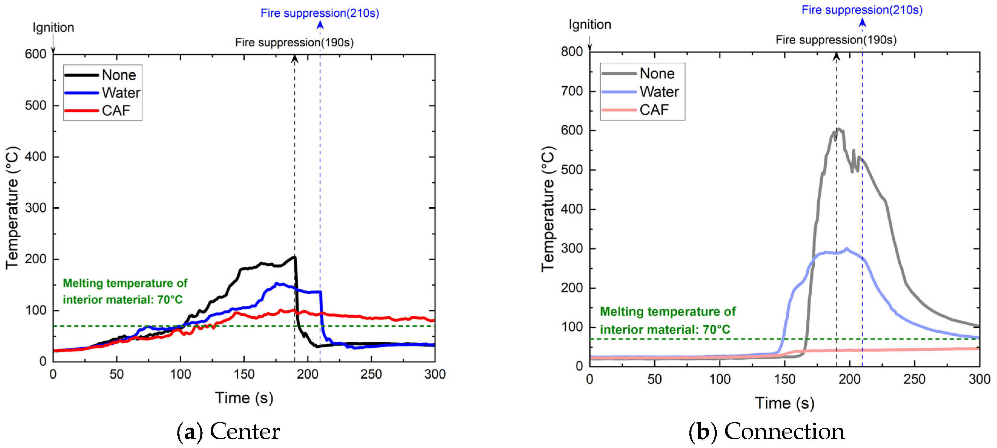
The temperatures at the center of the panel and at points of connection directly impacted by the fire over time were recorded to determine the effects of fire in an adjacent structure on the panel. In both “None” and “Water” conditions, the fire spread to the external surface, necessitating forced extinguishment. Subsequently, the maximum temperature was recorded before forced extinguishment. In comparing the highest surface temperatures across application conditions, significant temperature increases were revealed, demonstrating that the application of neither coating nor CAF caused any significant temperature reduction. However, water was effective in limiting the temperature increase (Figure 11).
The time required to reach 70 °C was evaluated. At the panel center, as shown in Table 3, the melting point was reached in 103, 102, and 113 s for untreated panels, those treated with water, and those treated with CAF, respectively. For the connection areas, the melting point was reached in 97, 101, and 109 s for untreated panels, those treated with water, and those treated with CAFS, respectively. Upon reaching these temperatures, the temperature subsequently increased under the “None” and “Water” conditions. However, the rate of increase in temperature decreased with the application of CAF. This effect was attributable to the formation of dry foam (with an air-to-foam ratio of 1:14). This effect yielded a more pronounced surface adhesion than water and contained less moisture; thus, it evaporates more slowly than water [29,30,31]. Despite the initial application of water yielding a transient reduction in surface temperature owing to the cooling effects of evaporation, temperatures subsequently increased after water evaporation. The temperatures at the connection points were consistently higher than those at the panel center under all conditions. The maximum temperature difference was 253.6 °C without the application and 83.1 °C in the presence of water.
The efficacy of water and CAF as thermal barriers was examined by comparing untreated panels with those treated with water, focusing on the panel center and connection areas. In scenarios where the conditions were either “None” or “Water,” and the fire had spread to the surface, forced extinguishment was conducted. Moreover, the average temperatures were calculated based on the readings obtained before this action. Consequently, as shown in Table 4, the average temperature at the panel center was approximately 13.5% lower with water treatment and 25.2% lower with CAF than with “None” conditions. The application of CAF yielded temperatures 13.6% lower than those in the water treatment group. At the connection points, the mean temperature reduction was approximately 35% with water and 55% with CAFS compared to the “None” condition. The application of CAF yielded a temperature reduction of 30.8% compared to water treatment.

3.2.2. Core Temperature

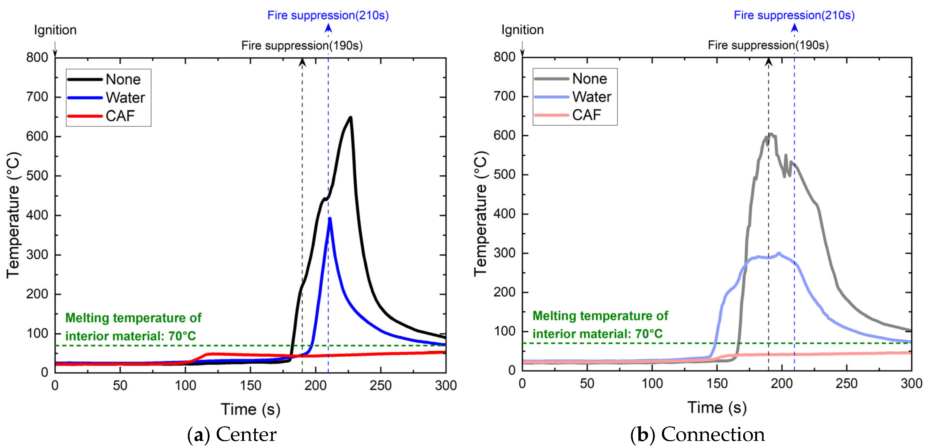
A comparison of the temperature changes at the center of the sandwich panel revealed that the temperature increased in the following order: None, Water, and CAF (Figure 12). The mean temperature was observed to be 49.5 °C and 79.3 °C lower in the “Water” and “CAF” conditions, respectively, compared to that in the “None” condition. As shown in Table 5, this indicates that the application of water or agents to the panel surface was approximately 42.1% and 67.4% more effective, respectively, in terms of heat insulation of the core. Similarly, the temperature increase at the sandwich panel connections followed the same pattern as that at the center. The mean temperature differential between “Water” and “CAF” conditions and the “None” condition was 48.4 °C and 117.5 °C, respectively. This indicated that the surface treatment was approximately 32.1% and 78.0% more effective in preventing heat penetration, respectively.
A thermocouple was positioned within the panel core to determine whether the 70 °C insulation melting point was reached. In the absence of any treatment, the melting point exceeded 183 and 167 s at the center and connection, respectively. However, under the water treatment, it reached 197 and 149 s, respectively. Moreover, the maximum temperatures at the center and connection did not reach the melting point of the insulation, indicating that the dry foam effectively prevented heat transfer from the surface inward (Table 6). This underscores the superiority of CAF over “None” and “Water” conditions.
The superior performance of CAF can also be attributed to its porous microstructure and slower evaporation behavior, which provide lower effective thermal conductivity and enhanced heat absorption through water evaporation. Previous studies have similarly reported that CAF exhibits slower evaporation rates and improved thermal insulation compared to water-based suppression agents, supporting the present findings. Moreover, the excellent performance of CAF can be explained quantitatively by both its porous structure and the latent heat of water evaporation. Typical thermal conductivity values for foams of comparable expansion ratios range between 0.03–0.05 W/m·K, which are significantly lower than those of solid structural materials, thereby reducing conductive heat transfer. In addition, the latent heat of water evaporation (~2257 kJ/kg) contributes to delaying the temperature rise within the panel core. Similar findings regarding the thermal insulation effects of foams have been reported in recent studies [23].
The temperature of the connection area was consistently higher than that at the center under all conditions. The temperature disparity was 73.9 °C in the “None” condition, 28.1 °C with “Water,” and 5.7 °C with “CAF.” This reflects the sensitivity of the core to the thermal conductivity of the material and the sensitivity of the surface to environmental variations. The efficacy of “Water” or “CAF” at the center of the panel and connection was evaluated compared to that in the “None” condition. Consequently, the mean temperatures at the center of the panel were approximately 42.1% and 67.4% lower under “Water” and “CAF” conditions, respectively, compared to that in the “None” condition. The application of CAFS yielded temperatures 43.7% lower than those in the “Water” treatment. At the panel connection, the average temperatures were approximately 32.1% and 78.0% lower under “Water” and “CAF” conditions, respectively, compared to those in the “None” condition. The temperature was 67.5% lower under CAF than under water treatment, compared with the increased rate in the temperatures of the core and surface.
The heat transfer pattern within a sandwich panel structure was examined during an external fire based on its surface-coating conditions. We compared the rate of temperature increase in the core relative to that on the surface. The rate of increase in temperature was determined using Equation (1) with reference to the maximum external temperature.
[{MAX.(Surface T. − Core T.)} ÷ (Surface T.)] × 100 [%]
Surface T.: Surface temperature [°C] and Core T.: Core Temperature [°C]
The experimental conditions were divided into three categories: None, Water, and CAFS. Table 7 lists the comparative analysis results of the rate of temperature increase in the core relative to the surface. Except for the panel connections, the rate of temperature increase was in the following order: None > Water > CAF.
Under the “None” condition, the increased rate in the core temperature exceeded that of the surface, with rates exceeding 100%. The mean rate of temperature increase from the core relative to the surface was calculated. The application of water reduced heat transfer by 7.1% and the application of CAF by 48.8% compared to the untreated panels. The substitution of water with CAF caused an additional reduction of 40.9% in the temperature increase.

3.2.3. Inner Temperature

The insulation layer of the sandwich panel melted in the absence of a coating by measuring the temperatures of its outer surface, core, and inner surfaces. However, partial melting occurred under water and fire-retardant coating conditions. These findings were used to determine the temperature increase in the compartments.
Initially, the rate of increase in temperature was determined by measuring the change in temperature from the initial temperature within the compartment to the maximum temperature. Under uncoated and water conditions, the heat and smoke from the external fire penetrated the compartment through gaps created by the melting of the insulation. As shown in Table 8, the rates of increase in temperature demonstrated that the uncoated condition exhibited the highest temperature increase rate at 47.2%, followed by water (10.7%) and CAF (2.6%). Under “CAF” conditions, the temperature increased by approximately 0.5 °C compared to the initial temperature, demonstrating that the fire retardant effectively blocked heat transfer into the interior (Figure 13).

4. Conclusions

This study evaluated the effectiveness of surface pre-application of water and CAF in delaying the spread of fire to adjacent sandwich panel buildings. A full-scale fire experiment was conducted to reflect realistic fire dynamics, overcoming the limitations of previous small-scale studies.
This study evaluated the effectiveness of surface pre-application of water and compressed air foam (CAF) in delaying fire spread in sandwich panel buildings through full-scale experiments. CAF treatment significantly reduced surface and core temperature rise, with core heat-blocking efficiency up to 78% higher than untreated panels and 67.5% higher than water application. The maximum internal temperature under CAF remained below the insulation melting point (53.3 °C), preventing material degradation, while CAF-treated joints showed the lowest temperature differentials, highlighting its role in blocking flame penetration through structural gaps. The superior performance of CAF was attributed to its dry foam structure (air-to-solution ratio of 1:14), which adhered effectively to surfaces and maintained a stable insulating layer with only minor loss due to gravity, unlike water that rapidly drained and evaporated. These findings verify CAF as a proactive exposure protection measure for industrial buildings constructed with sandwich panels.
While the study was limited by a small number of repetitions and did not assess long-term or environmental factors such as wind, humidity, or prolonged exposure, the results provide a strong empirical basis for considering CAF in both field operations and future regulatory frameworks. Future work should systematically examine CAF’s long-term adhesion under real environmental conditions, its scalability in large-scale applications, and its cost-effectiveness compared to conventional water-based methods. Addressing these factors will be critical for the practical adoption of CAF-based fire protection strategies in national safety standards and industrial practice.

Author Contributions

J.-H.Y.: Conceptualization, methodology, investigation, writing—original draft, project administration. T.-S.K.: Validation, writing—review & editing. T.-H.P.: Data curation, visualization. J.-S.K.: Supervision, writing—review & editing, corresponding author. All authors have read and agreed to the published version of the manuscript.

Funding

This research was supported by the Technology and Development to Support Firefighting Activities (2760000048), funded by the National Fire Agency of Korea.

Data Availability Statement

The data presented in this study are available on request from the corresponding author.

Acknowledgments

The funding agency had no role in the study design; collection, analysis, and interpretation of data; writing of the report; and decision to submit the article for publication.

Conflicts of Interest

The authors declared no potential conflicts of interest with respect to the research, authorship, and/or publication of this article.

Glossary

  • CAF, compressed air foam
A fire suppression medium consisting of a foam solution mixed with compressed air to form stable microbubbles. CAF adheres to surfaces, reduces heat transmission, and delays combustion through cooling and oxygen separation effects.
  • Pre-application
The advanced application of a fire suppression agent (e.g., water or CAF) onto a surface before flame exposure, intended to delay temperature increase and prevent structural ignition.
  • Class A fire
A type of fire involving ordinary combustible materials such as wood, paper, cloth, or plastics. These fires are characterized by the formation of glowing embers and are typically extinguished by cooling with water or foam-based agents. Class A fires are the most common in structural environments and are often used in standard fire suppression performance testing.
  • Heat blocking rate
A percentage metric indicating the reduction in heat transmission achieved by applying a treatment, calculated by comparing temperatures between treated and untreated samples.
  • Radiant heat flux
The rate at which thermal radiation energy is received per unit area, typically measured in kilowatts per square meter (kW/m2). It represents the intensity of fire exposure.
  • Connection (joint) area
The structural interface where sandwich panels are connected. These points are more vulnerable to heat penetration due to material gaps or weaknesses.
  • Melting point of insulation
The threshold temperature at which the panel’s core insulation (typically styrofoam) begins to degrade or melt, leading to potential fire spread inside the structure.
  • Dry foam (CAF application)
A form of CAF with reduced water content and higher foam concentration, designed to improve surface adhesion and prolong heat resistance.

References

  1. ASM International. ASM Handbook, Volume 1: Properties and Selection—Irons, Steels, and High-Performance Alloys; ASM International: Materials Park, OH, USA, 1990. [Google Scholar] [CrossRef]
  2. Callister, W.D., Jr.; Rethwisch, D.G. Materials Science and Engineering: An Introduction, 10th ed.; John Wiley & Sons: Hoboken, NJ, USA, 2020; Available online: https://books.google.co.kr/books?id=dmoTEQAAQBAJ (accessed on 15 August 2025).
  3. Chen, J.; Hamed, E.; Gilbert, R.I. Structural Performance of Concrete Sandwich Panels under Fire. Fire Saf. J. 2021, 121, 103293. [Google Scholar] [CrossRef]
  4. Campbell, R.B. Structure Fires in Warehouse Properties; National Fire Protection Association, Fire Analysis and Research Division: Quincy, MA, USA, 2016; Available online: https://www.nfpa.org/education-and-research/research/nfpa-research/fire-statistical-reports/warehouse-structure-fires (accessed on 15 August 2025).
  5. CFPA-E. Fire Safety in Warehouses. CFPA-E Guideline No. 35. 2017. Available online: https://cfpa-e.eu/app/uploads/2022/04/CFPA_E_Guideline_No_35_2017_F.pdf (accessed on 15 August 2025).
  6. Kim, J.Y. Conduct Planning Research of Evacuation Improvement and Risk-Based Management for Fire Safety of Storage Facilities; Ministry of Land, Infrastructure, and Transport: Sejong, Republic of Korea, 2021; Available online: https://www.codil.or.kr/viewDtlConRpt.do?gubun=rpt&pMetaCode=OTKCRK220002 (accessed on 15 August 2025).
  7. Grant, G.; Brenton, J.; Drysdale, D. Fire Suppression by Water Sprays. Prog. Energy Combust. Sci. 2000, 26, 79–130. [Google Scholar] [CrossRef]
  8. Nam, S.W. Design & Construction of Fire Protection Systems; Sungandang: Seoul, Republic of Korea, 2018; Available online: https://www.cyber.co.kr/book/item/8480 (accessed on 15 August 2025).
  9. Kwon, J.-S.; Park, T.-H.; Shin, Y.M.; Lim, Y.R.; Lee, J.H. An Experimental Study on Fire Prevention in Buildings Using Emergency Extinguishing Equipment in the Presence of Flying Sparks from Wildfires. Fire Sci. Eng. 2022, 36, 114–121. [Google Scholar] [CrossRef]
  10. Kim, H.S.; Hwang, I.J.; Kim, Y.J. Thermal Characteristics of Fire-Protection Foams Exposed to Radiant Heating. In Proceedings of the Korean Society of Mechanical Engineers Spring and Autumn Conference, Daejon, Republic of Korea, 3–5 November 2004; Available online: https://koreascience.or.kr/article/CFKO200433239309636.page (accessed on 15 August 2025).
  11. Taylor, R.G. Compressed Air Foam Systems in Limited Staffing Conditions; National Fire Academy: Emmitsburg, MD, USA, 1997. Available online: https://apps.usfa.fema.gov/pdf/efop/efo27966.pdf (accessed on 15 August 2025).
  12. Magrabi, S.A.; Dlugogorski, B.Z.; Jameson, G.J. The Performance of Aged Aqueous Foams for Mitigation of Thermal Radiation. Dev. Chem. Eng. Miner. Process. 2000, 8, 93–112. [Google Scholar] [CrossRef]
  13. Boyd, C.F.; Marzo, M.D. The Behavior of a Fire-Protection Foam Exposed to Radiant Heating. Int. J. Heat Mass Transf. 1998, 41, 1719–1728. [Google Scholar] [CrossRef]
  14. National Fire Protection Association (NFPA). Standard for Low-, Medium-, and High Expansion Foam (NFPA 11); NFPA: Quincy, MA, USA, 2021; Available online: https://www.nfpa.org/codes-and-standards/nfpa-11-standard-development/11 (accessed on 15 August 2025).
  15. Feng, D.Y. Analysis on Influencing Factors of the Gas-Liquid Mixing Effect of Compressed Air Foam Systems. Procedia Eng. 2013, 52, 105–111. [Google Scholar] [CrossRef]
  16. Zhang, J.; Delichatsios, M.; O’Neillet, A. Assessment of Gas Cooling Capabilities of Compressed Air Foam Systems in Fuel- and Ventilation-Controlled Compartment Fires. J. Fire Sci. 2011, 29, 543–554. [Google Scholar] [CrossRef]
  17. Kim, T.-S.; Park, T.-H.; Park, J.-H.; Yang, J.-H.; Han, D.-H.; Lee, B.-C.; Kwon, J.-S. Thermal Characteristics of Fire Extinguishing Agents in Compartment Fire Suppression. Sci. Prog. 2024, 107, 00368504241263435. [Google Scholar] [CrossRef]
  18. Zhao, H.; Liu, J.S. The Feasibility Study of Extinguishing Oil Tank Fire by Using Compressed Air Foam System. Procedia Eng. 2016, 135, 61–66. [Google Scholar] [CrossRef]
  19. Rappsilber, T.; Krüger, S. Design Fires with Mixed-Material Burning Cribs to Determine the Extinguishing Effects of Compressed Air Foams. Fire Saf. J. 2018, 98, 3–14. [Google Scholar] [CrossRef]
  20. Kim, A.K.; Crampton, G.P. Evaluation of the Fire Suppression Effectiveness of Manually Applied Compressed-Air-Foam (CAF) System. Fire Technol. 2012, 48, 549–564. [Google Scholar] [CrossRef]
  21. Madrzykowski, D. Study of the Ignition Inhibiting Properties of Compressed Air Foam; National Institute of Standards and Technology: Gaithersburg, MD, USA, 1988; NISTIR 88–3880. Available online: https://www.govinfo.gov/content/pkg/GOVPUB-C13-59e80dc51906e3bbe9774e103f1170c0/pdf/GOVPUB-C13-59e80dc51906e3bbe9774e103f1170c0.pdf (accessed on 15 August 2025).
  22. Republic of Korea. Civil Act, Article 242: Construction near Boundary Line. 2025. Available online: https://elaw.klri.re.kr/eng_service/lawView.do?hseq=29453&lang=ENG (accessed on 15 August 2025).
  23. Chen, Y.; Li, X.; Wang, H.; Zhang, Y.; Liu, J. Multi-Scale Experimental Study on Properties of Compressed Air Foam and Pressure Drop in the Long-Distance Vertical Pipe. J. Build. Eng. 2024, 96, 110397. [Google Scholar] [CrossRef]
  24. Park, T.-H.; Park, J.-H.; Yang, J.-H.; Lee, B.-C.; Kim, T.-D.; Kim, B.-J.; Kwon, J.-S. Experiments on the Application of Class A and B Fires to Derive the Optimum Air Ratio of Compressed Air Foam Systems. Fire Sci. Eng. 2023, 37, 38–43. [Google Scholar] [CrossRef]
  25. Kim, A.K.; Dlugogorski, B.Z.; Mawhinney, J.R. Effect of Foam Additives on the Fire Suppression Efficiency of Water Mist. In Proceedings of the Halon Options Technical Working Conference, Albuquerque, NM, USA, 3–5 May 1994; pp. 347–358. Available online: https://www.nist.gov/system/files/documents/el/fire_research/R9402226.pdf (accessed on 15 August 2025).
  26. Hipkins, D.B. Class A Foam Water Sprinkler Systems; University of Canterbury: Christchurch, New Zealand, 1999; Available online: https://ir.canterbury.ac.nz/server/api/core/bitstreams/4df3b805-9337-441a-8c8c-623b6197a623/content (accessed on 15 August 2025).
  27. Hurley, M.J.; Gottuk, D.T.; Hall, J.R., Jr.; Harada, K.; Kuligowski, E.D.; Puchovsky, M.; Torero, J.L.; Watts, J.M., Jr.; Wieczorek, C.J. SFPE Handbook of Fire Protection Engineering, 5th ed.; Springer: New York, NY, USA, 2015; Available online: https://www.sfpe.org/publications/handbooks/sfpehandbook (accessed on 15 August 2025).
  28. Ahn, J.K. Technology Development Trends of Sandwich Panel Fireproof Wall for Architecture; Korea Institute of Construction Technology: Goyang-si, Republic of Korea, 2021; Available online: https://www.xn--z69aksb59ee70eilbh1mizbn16d.kr/board.es?mid=a10105070000&bid=cntrbclmn&list_no=17138 (accessed on 15 August 2025).
  29. Boyd, W.K.; Marzo, R.J. Evaluation of Class A Foams for Structural Firefighting. Fire Technol. 1998, 34, 123–138. [Google Scholar]
  30. Back, G.G.; Beyler, C.L. Flammability of Class A Foam Solution and Water Mist. Fire Saf. J. 1995, 24, 125–150. [Google Scholar]
  31. Lattimer, B.Y.; Trelles, J.P.; Roby, R.J. Heat Transfer from Fires to Fuel Surfaces Covered with Firefighting Foams. Fire Saf. J. 2004, 39, 241–268. [Google Scholar] [CrossRef]
Figure 1. Structure and data analysis positions of preliminary experiments.
Fire 08 00359 g001
Figure 2. Structures used in the main experiment.
Fire 08 00359 g002
Figure 3. Information of exposed surface at structure used in the experiment.
Fire 08 00359 g003
Figure 4. Thermocouple position with a sectional view of the structure used in the experiment.
Fire 08 00359 g004
Figure 5. Measurement results of heat flux.
Fire 08 00359 g005
Figure 6. Preliminary experiment steps.
Fire 08 00359 g006
Figure 7. Conditions of pre-experiments (Top view).
Fire 08 00359 g007
Figure 8. Conditions of main experiments.
Fire 08 00359 g008
Figure 9. Temperature results of preliminary experiments.
Fire 08 00359 g009
Figure 10. Procedure of main experiments. “Finish” indicates the termination of measurement at 800 s for all conditions (as shown in Figure 9, graphs are truncated at 800 s).
Fire 08 00359 g010
Figure 11. Temperature of the sandwich panel surface.
Fire 08 00359 g011
Figure 12. Temperature of sandwich panel cores.
Fire 08 00359 g012
Figure 13. Temperature inside the compartment.
Fire 08 00359 g013
Table 1. Equipment damage criteria based on radiant heat flux exposure time.
Heat Flux (kW/m2)Damaged Equipment
12.5Minimum energy required to ignite wood by flame
25.0Minimum energy required to ignite wood through prolonged exposure without flame
Table 2. Heat blocking rate in preliminary experiments.
Measurement Height (m)Heat Blocking Rate (%)
None/Water *None/CAF **Water/CAF ***
0.631.822.5(−)12.0
1.033.935.52.5
1.427.338.117.5
* Calculation method: [{(None temp.) − (Water temp.)}/None temp.] × 100 [%]. ** Calculation method: [{(None temp.) − (CAF temp.)}/CAF temp.] × 100 [%]. *** Calculation method: [{(Water temp.) − (CAF temp.)}/CAF temp.] × 100 [%].
Table 3. Average temperature and time to melt for sandwich panel insulation at the surface.
ConditionsAverage and Maximum Temperature (°C) (Time to Reach Melting Temperature [s])
NoneWaterCAF
Avg.
(°C)
Max.
(°C)
Time
(s)
Avg.
(°C)
Max.
(°C)
Time
(s)
Avg.
(°C)
Max.
(°C)
Time
(s)
Center92.7204.110380.3153.610269.4101.2113
Connection166.6457.7 97108.4236.610175.0100.5109
Differential73.9253.6628.183.115.70.74
Temperature differential between core and connection (higher value–lower value).
Table 4. Heat blocking rate at the surface of the sandwich panel.
Measurement PointsHeat Blocking Rate (%)
None/Water *None/CAF **Water/CAF ***
Center13.525.213.6
Connection35.055.030.8
* Calculation method: [{(None temp.) − (Water temp.)}/None temp.] × 100 [%]. ** Calculation method: [{(None temp.) − (CAF temp.)}/CAF temp.] × 100 [%]. *** Calculation method: [{(Water temp.) − (CAF temp.)}/CAF temp.] × 100 [%].
Table 5. Heat blocking rate at the core of the sandwich panel.
Measurement PointsHeat Blocking Rate (%)
None/Water *None/Foam **Water/Foam ***
Center42.167.443.7
Connection32.178.067.5
* Calculation method: [{(None temp.) − (Water temp.)}/None temp.] × 100 [%]. ** Calculation method: [{(None temp.) − (CAF temp.)}/CAF temp.] × 100 [%]. *** Calculation method: [{(Water temp.) − (CAF temp.)}/CAF temp.] × 100 [%].
Table 6. Comparison of temperature differentials and melting point times under different pre-application conditions.
ConditionsAverage and Maximum Temperature (°C) (Time to Reach Melting Temperature [s])
NoneWaterCAF
Avg.
(°C)
Max.
(°C)
Time
(s)
Avg.
(°C)
Max.
(°C)
Time
(s)
Avg.
(°C)
Max.
(°C)
Time
Center117.7649.4 183.068.2393.4 197.038.453.3 -
Connection150.7604.1 167.0102.3300.4 149.033.246.3 -
Differential33.0−45.3 −16.034.1−93.0 −48.0−5.2−7.0-
Temperature differential between core and connection (°C): (higher value–lower value). Note: For CAF, the 70 °C melting point was not reached within the 800 s experiment duration; hence, the Time entry is left blank.
Table 7. Temperature increase rate of each condition.
ConditionsRate of Temperature Rise (%) *
NoneWaterCAF
Center110.075.457.1
Connection103.0121.758.3
Average106.598.657.7
* Calculation method: [{(Maximum temp.) − (Initial temp.)}/Initial temp.] ×100 [%].
Table 8. Temperature increase rate compared to the initial temperature.
ConditionsInitial Temperature (°C)Maximum Temperature (°C)Temperature
Increase Rate (%) *
None18.627.447.2
Water20.823.010.7
CAF21.822.32.6
* Calculation method: [{(Initial temp.) − (Maximum temp.)}/Initial temp.] ×100 [%].
Disclaimer/Publisher’s Note: The statements, opinions and data contained in all publications are solely those of the individual author(s) and contributor(s) and not of MDPI and/or the editor(s). MDPI and/or the editor(s) disclaim responsibility for any injury to people or property resulting from any ideas, methods, instructions or products referred to in the content.