Technical Note

Double vs. Single Shear in Dowelled Timber Connections Under Fire Conditions, Thermal Analysis

by
Elza M. M. Fonseca
ISEP, Instituto Politécnico do Porto, R. Dr. António Bernardino de Almeida, 4249-015 Porto, Portugal
Fire 2025, 8(8), 310; https://doi.org/10.3390/fire8080310
Submission received: 24 July 2025 / Revised: 1 August 2025 / Accepted: 4 August 2025 / Published: 5 August 2025
(This article belongs to the Special Issue Advances in Structural Fire Engineering)

Abstract

The main aim of this work is to compare double- or single-designed connections with wooden members and internal steel fasteners under fire conditions. Theoretical methods following Eurocodes will be used to assess the load-bearing capacity of the connections and to compare the effects of double and single shear. Several parameters will be examined to determine the load capacity. Furthermore, a numerical thermal analysis using finite element methods will be performed to estimate the temperatures inside the connections and compare them. The results show that the double shear connection in steel-to-timber, with a steel plate of any thickness as the central element and with a higher density of wood material, has better mechanical and fire resistance. Lower temperatures were also observed in this connection type in the wood material and along the length of the dowel.

1. Introduction

With increasing problems with climate change, the benefit of wood in building construction presents a solution to solve it. Wood is a sustainable material, and its use can address the present problem of climate change when compared to other materials, needing only minimal processing compared to materials such as steel, concrete, or aluminium. The main advantage is the positive contribution to the carbon cycle and the low energy consumption throughout the process. Wood is a natural resource that can be replanted, making it a renewable option, and it absorbs carbon dioxide as it grows, storing it and reducing the amount of greenhouse gases in the atmosphere. Wood can be reused in different projects, and, at the end of its useful life, it can be recycled, reducing waste. This material can be used in light and fast construction, reducing the time and environmental impact of construction. Furthermore, it has thermal and acoustic insulation properties, which can reduce energy consumption and improve comfort in buildings. But it is important to use wood from certified forests, which guarantee that the wood was harvested in a way that preserves biodiversity, protects the rights of local communities, and ensures the replanting of the forest. Furthermore, wood demonstrates the advantage of fire resistance and has an extensive application in construction and engineering, such as tall timber buildings, floor and roof decking, wall partitions, and hybrid systems [1,2,3]. In these applications, the scientific community has become increasingly interested and is assessing structural safety while updating the current regulations.
The fire resistance of timber connections is an interesting scientific topic because these structural elements depend on the growth of the char layer and the reduction in the residual cross-section, which influence their load-bearing capacity [4]. All timber species develop a protective char layer during fire, but the degree of fire protection depends more on density and physical structure. Furthermore, recent research shows that moisture content, which varies less in glued laminated timber; density; and chemical components (mainly the lignin content) are directly correlated [5]. Denser woods and well-maintained char layers provide the most effective fire resistance [6]. Products like cross-laminated and glulam wood, considered engineered timber, follow analogous charring principles, but delamination or char fall-off can reduce the protective effect [6].
Performance analysis of connections in fire is multifaceted because it involves different materials and factors, geometries, and dowel arrangements [7]. Both steel and wood materials exhibit distinct behaviours, and the interface between both often exhibits behaviour that is distinct from either material alone due to the connection method and the geometric design, which play crucial roles in the overall performance.
Wood material under fire undergoes the degradation of physical and chemical properties. The boundary between the charred and non-charred wood acts as a modification zone, characterised by a threshold value of 300 °C, according to Eurocode 5, part 1-2 [8]. However, wood can have good mechanical qualities, such as strength and density [9]. Eurocode 5, part 1-2 [8], is the standard for the fire design of timber structures and their performance, where temperature plays a major role in determining fire resistance, as it directly affects the charring rate, residual cross-section, strength loss, and degradation of material properties. This standard presents simplified methods for calculating temperature and strength reduction during fire exposure. The thermal properties of wood vary significantly with temperature and must be defined according to Eurocode 5, part 1-2 [8]. This standard provides design values for density, thermal conductivity, and specific heat of wood. Following Eurocode 5, part 1-2 [8], timber connections under fire conditions can be protected by adding timber panels, wood-based panels, or gypsum plasterboard types A, H, or F. This brief overview [10,11] highlights the general material properties used in these components. Quantifying the thermal properties at high temperatures is essential for developing heat transfer models in connections and assessing their fire resistance. Some of these properties are also covered in Eurocode 3, part 1-2, for steel [12] and Eurocode 5, part 1-2 [8], for wood.
According to different connection types, geometries, and materials used together, timber-to-timber and steel-to-timber connections, for different conditions applied in single or double shear, should be distinguished [13]. Furthermore, something of great relevance is the presence of the bolts, which greatly influence the behaviour of connections, especially under fire conditions [13]. Further studies will be needed to augment and strengthen all decisions that support the new standards. Related to timber structures, the second generation of Eurocode 5 is undergoing revision, with availability scheduled for 2025 and publication in 2027 [14,15]. A revision with additional guidance to increase the robustness of timber elements will be considered, focusing on direct design methods [15]. This is a way to keep new design requirements up to date.
Timber connections are often the limiting factor in the fire resistance of timber structures [4]. Significant factors include fasteners, thickness, geometry, and fire protection. Non-metallic connectors and protective strategies can significantly improve performance [4]. More studies of different connection types are necessary. The lack of research related to the thermal behaviour of joints with axially loaded connectors is remarkable, and more research is needed to provide information about how they might be more effective in fire situations [4]. Advanced calculation methods or experimental tests may be needed for engineered wood products or complex assemblies.
Following this, the primary goal of this work is to present a theoretical methodology for predicting the safety of connections in double versus single shear, defining the load-carrying capacity, and establishing the number of dowels required for the connection. This study continues the findings from the author’s previous investigations concerning the effect of steel dowels on timber connections subjected to fire [16,17], where the shear effect is not compared between connection types. The connections were assessed for various tensile loads applied parallel to the grain, dowel diameters, and wood material densities. The computational simulations presented are established with the finite element method, utilising thermal analysis with nonlinear materials, which enables a comparison between single and double shear connections under fire situations. This is a technical note, where the main objective is the comparison between different types of joints using a different program and considering some distinct study variables. Studies in this context are already beginning to appear in the literature, but consolidation requires different validation studies.

2. Materials and Methods

2.1. Materials and Fire Curve

The main objective of this investigation is to present a theoretical and numerical formulation that can be used in the project of timber connections in double or single shear with steel material, together with dowels. To achieve the main results, the choice of the specific sizes depends on the type of timber connection and the needed load-carrying capacity. Fastener strength depends on several issues, such as the applied load, wood density, direction of the wood grain, fastener location, edge, and distances from the ends of the timber connection [17,18,19,20]. In general, fastener strength concerns the mechanical stress that it can resist before failing.
Three different densities of glued laminated timber (referred to as glulam or GL) were used for the investigation into connections performed in this study, and S275 steel material [19] was used for the connectors (dowels and plates), as per the orientations [11,17,18,19]. In the homogeneous glulam GLxh, the value of x represents the strength class. All lamellae of the cross section belong to the same strength class and are predominantly made from softwood. Glulam is an engineered wood product manufactured by glueing together pieces of timber, widely used in different building projects, in a range of strength classes. Glulam is characterised by its high load-carrying capacity, stability, and the ability to form different-shaped components. The timber is technologically dried and generally contains a moisture content of between 12 and 20% [21].
For thermal analysis, heat transfer is influenced by material density, thermal conductivity, and specific heat. The properties of wood vary with temperature, as outlined by Eurocode 5, part 1-2 [8], and are shown in Figure 1. For steel, density is considered constant across the entire temperature range experienced during a fire. However, thermal conductivity and specific heat depend on temperature, as illustrated in Figure 1, Eurocode 3, part 1-2 [12].
The fire is characterised as a thermal analysis, which is used to understand how the connection will respond to the exposure. This analysis will allow the analysis of the temperature distribution over time, thus resulting in the thermal response of the connection [9]. The fire curve ISO 834 will be used in the computational model because it is recommended in fire tests to rate structural and separating elements [22], described by Equation (1) and in Figure 1.
θ = 20 + 345   l o g 10 8 t + 1
where t is the time in minutes, and θ is the gas temperature in the fire compartment in °C.

2.2. Theoretical Methods

The existing theoretical method follows the easy equations of Eurocode to determine the dimensions of the connections. Eurocode 5, part 1-1 [18], offers expressions to estimate the load-carrying capacity of several connection types. For the design of the connection, the aim is to determine the number of dowels and their dimensions. The equations presented in Table 1 are used for double shear connections, and those in Table 2 are used for single shear connections [9,11], where the main variables are as follows:
Fv,Rk is the characteristic load-carrying capacity per shear plane per fastener (Table 1).
ti is the thickness of the timber side member (i = 1, 2); respectively, the smaller and the middle member.
d is the fastener diameter.
β is the ratio between the embedment strength of the members, equal to 1.
Fαx,Rk represents the characteristic axial withdrawal capacity of the fastener.
fu,k is the material characteristic tensile strength.
ρk is the characteristic density of the wood.
My,Rk is the characteristic fastener yield moment calculated according to the dowel diameter and the material strength, Equation (2).
fh,i,k is the characteristic embedment strength in the timber element (i = 1, 2), Equation (3).
M y , R k = 0.3 f u , k d 2.6
f h , i , k = 0.082 1 0.01 d ρ k
The design tensile strength along the grain ft,0,d needs to be equal to or higher than the design tensile stress along the grain. The tensile strength characterizes a reduced value of the characteristic tensile strength along the wood grain, due to safety factors: the modification factor for load duration and moisture content kmod is equal to 0.8; for medium-term action of the load duration class and the partial factor for material properties, γM is 1.25 [8], as in Expression 4.
f t , 0 , d = k m o d   f t , 0 , k γ M
With the calculation Fv,Rk, from Table 1 and Table 2, it is possible to obtain the number of bolts N, Equation 6, due to the tensile applied load Ed and the calculated design characteristic load-carrying capacity Fv,Rd.
F v , R d = k m o d   F v , R k γ M
N = E d F v , R d
Additionally, Table 1 and Table 2 present the failure modes that may occur for each calculated characteristic load-carrying capacity per shear plane per fastener. To account for the effects dependent on the geometry of the connection, the embedment strength of the wood, the bending strength of the fastener, and the characteristic load-carrying capacity need to be the minimum value derived from these expressions.
The failure types or the modes of rupture in wood refer to the different ways in which it can fail under stress, normally categorised by tension, compression, shear, and the orientation relative to the wood grain. The failure modes are represented by the following: Mode I, which denotes to an embedment failure of the connected materials without any yielding of the fastener; Mode II is a combination of embedment failure of the connected material and single yield failure per shear plane of the fastener; and Mode III refers to a combination of embedment failure of the connected material and multiple yield failures of the fastener [20]. Failure Modes II and III suppose a ductile fastener that can form plastic hinges [20].
To determine the dowel position for the connection, it will be necessary to follow the procedures according to Eurocode 5, part 1-1 [18]. Table 3 represents the equations that allow the calculation of these variables, depending on the angle α between the direction of the tensile load and the loaded edge (or end). Eurocode 5, part 1-1 [18], imposes that the dowel diameter should be greater than 6 mm and less than 30 mm.
Using all identified procedures, the results in Figure 2 and Figure 3 represent the relationship among the number of dowels dependent on the applied load and the dowel diameter for each type of connection, using different variables (three different glulam timber qualities, two different dowel diameters, and different applied tensile loads).
According to the parameters used in all easy equations, some relationships are obtained. The number of dowels is very similar between the chosen connection types, double and single, for the same applied load condition. However, when comparing the results of Figure 2 and Figure 3 for steel-to-timber with thin steel plates as the external members in double shear and for steel-to-timber with a thick steel plate in single shear, respectively, the number of dowels is slightly higher in the steel-to-timber single shear connection with a thick steel plate. These conclusions agree with other works [9,23]. The number of dowels is fewer in double shear connections in steel-to-timber with a steel plate of any thickness as the central member, which represents the connection with higher mechanical resistance.
In both studied connections, when the use of dowels decreases in diameter, the variation in the number of dowels improves. Also, for any connection type, wood material with high density combined with a higher dowel diameter needs fewer dowels. The better the wood, the stronger and stiffer the connections.
To simulate the fire effect using the finite element method, six different connections are selected to present the results. The total number of finite element models is equal to eighteen, due to the three selected glulam woods. The design characteristic load-carrying capacity per shear plane, obtained by fasteners in these connections, is shown in Table 4, when a tensile applied load Ed is equal to 20 kN.
As calculated, steel-to-timber with a steel plate of any thickness as the central member with high-density material and a higher dowel diameter has a higher load-carrying capacity. Steel-to-timber with a thick steel plate with less-dense material has a lesser strength capability. The characteristic load-carrying capacity improves with higher wood density, and comparing the connections, shear double connections generally have better load-carrying design characteristics.
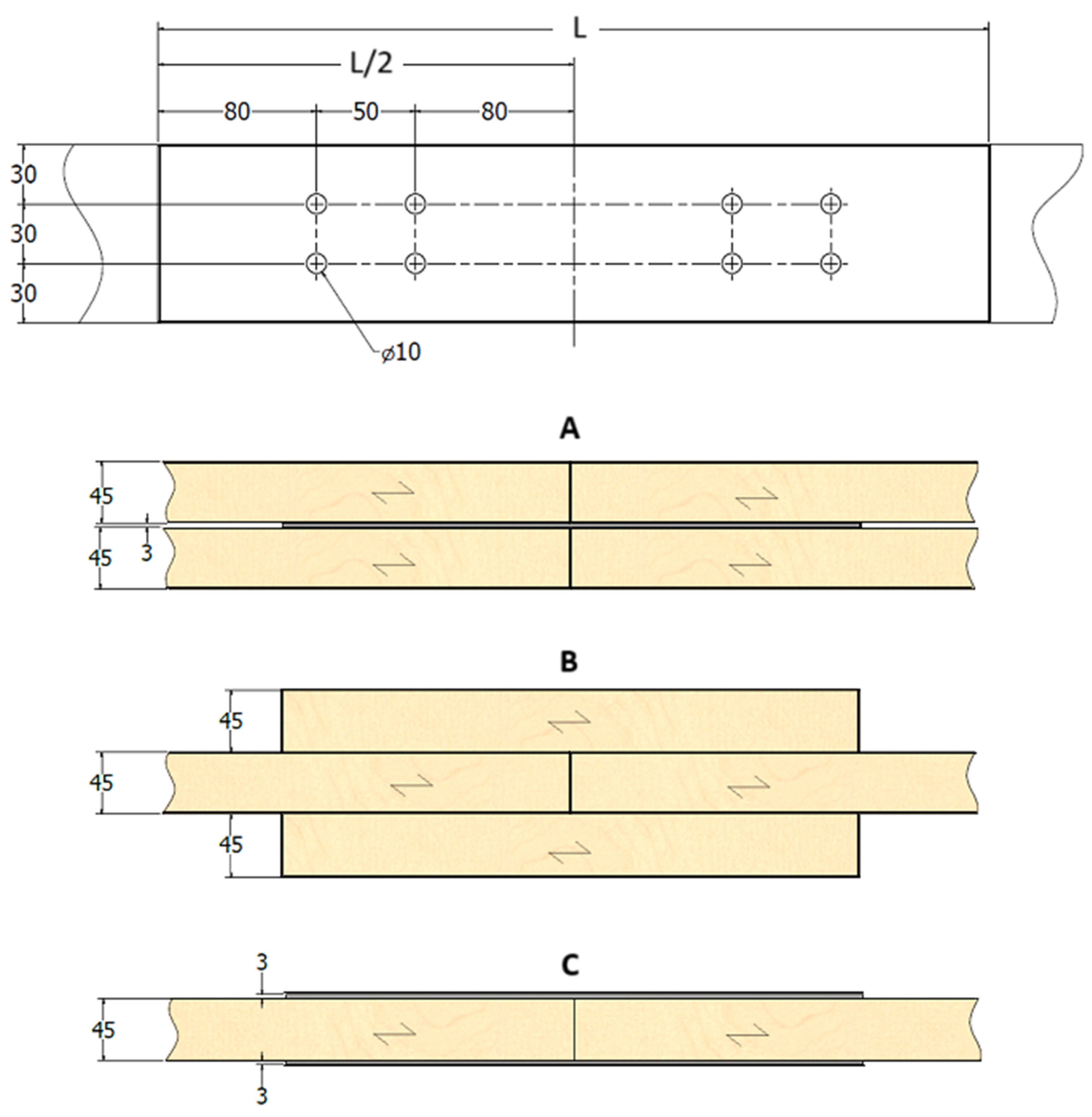
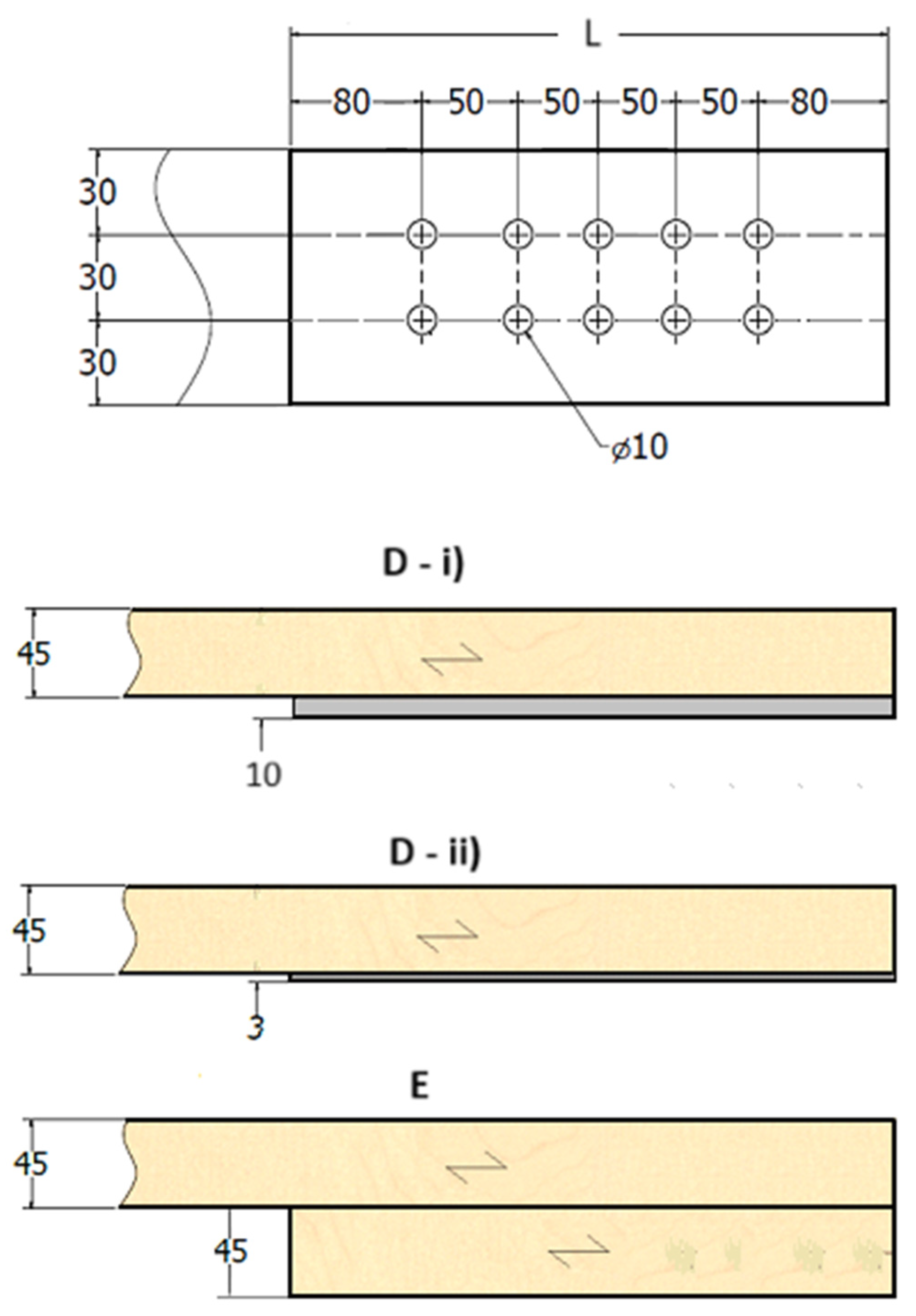
Finally, with this calculation, it is feasible to acquire the number of dowels to be used for each connection. The dimensions of the connections were previously chosen: the width (L), height (H = 90 mm), and depth (W = 93, 135, 51 mm, for A, B and C, and W = 50, 48 and 90 mm, for D-i), D-ii) and E, respectively) obtained by the thickness of the timber (t1 = 45 mm or t2 = 45 mm, where 1 or 2 mm are considered to the tolerances in construction) and steel plates (ts = 3 or 10 mm). According to the number of dowels, it will be necessary to calculate the distance parallel and perpendicular to the grain between the dowels, as well as the edge/end distances between the dowels and the plates (a1 = 50 mm, a2 = 30 mm, a3,t = 80 mm, and a4,c = 30 mm), as represented in Figure 4 and Figure 5.

2.3. Computational Method

A three-dimensional computational model was built with the ANSYS® program to conduct the thermal analysis, considering the nonlinear properties of wood and steel materials. According to the fire exposure following the standard fire curve ISO 834, equation 1, the boundary conditions are related to convection and radiation. All sides of the connection will be exposed to fire. The initial temperature in the numerical model was considered equal to 20 °C. The convection coefficient is 25 W/m2K [22]. The emissivity of the fire is considered equal to 1 [22]. For steel, the emissivity is equal to 0.7, Eurocode 3, part 1-2 [12]. The wood emissivity is also equal to 0.8, Eurocode 5, part 1-2 [8].
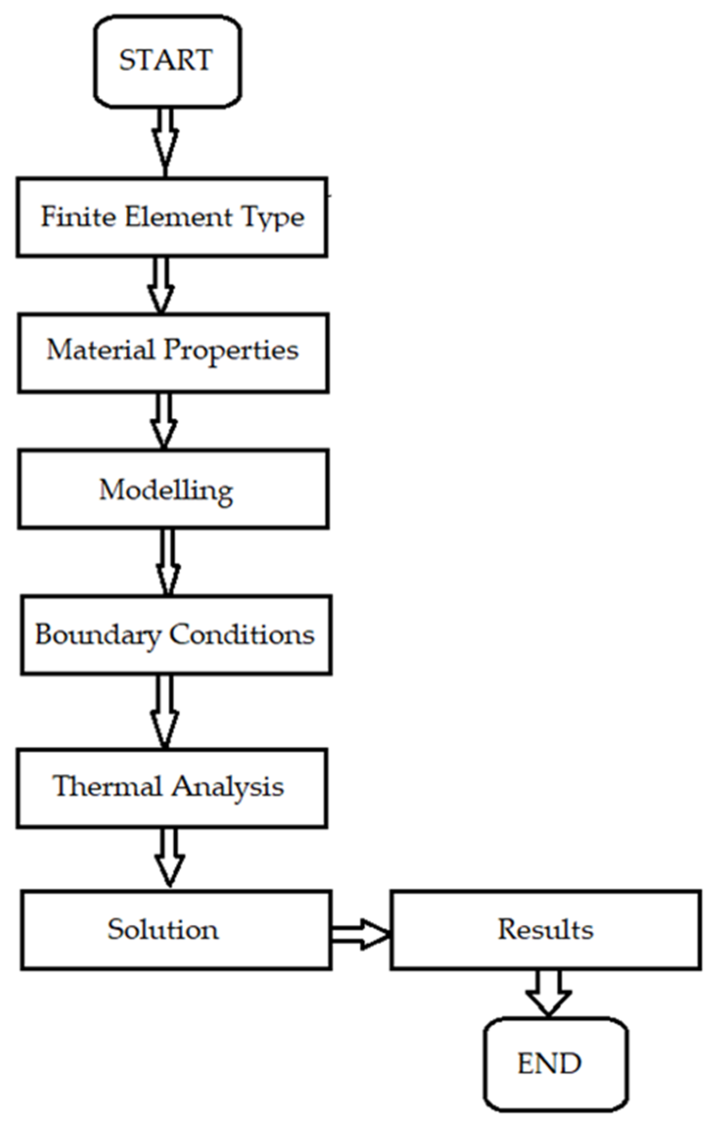
For this type of analysis, the software employs the Newton–Raphson method to determine the new equilibrium position during the transient process, which is the time-dependent thermal analysis used. To represent the mesh, the finite element SOLID278 with a 3D thermal conduction capability was chosen. This element has 8 nodes with one degree of freedom, the temperature, for each node. The flowchart in Figure 6 represents all processes and steps needed to obtain the thermal solution.
In the thermal model, perfect contact between elements was considered as uninterrupted heat transfer through all parts. In reality, and due to the existing manufacturing factors like surface roughness, interfacial layers, and the presence of voids between the components, an air gap between parts could be used in the finite element analysis. It was not considered in the present work, only because high temperatures were reached in the connections.
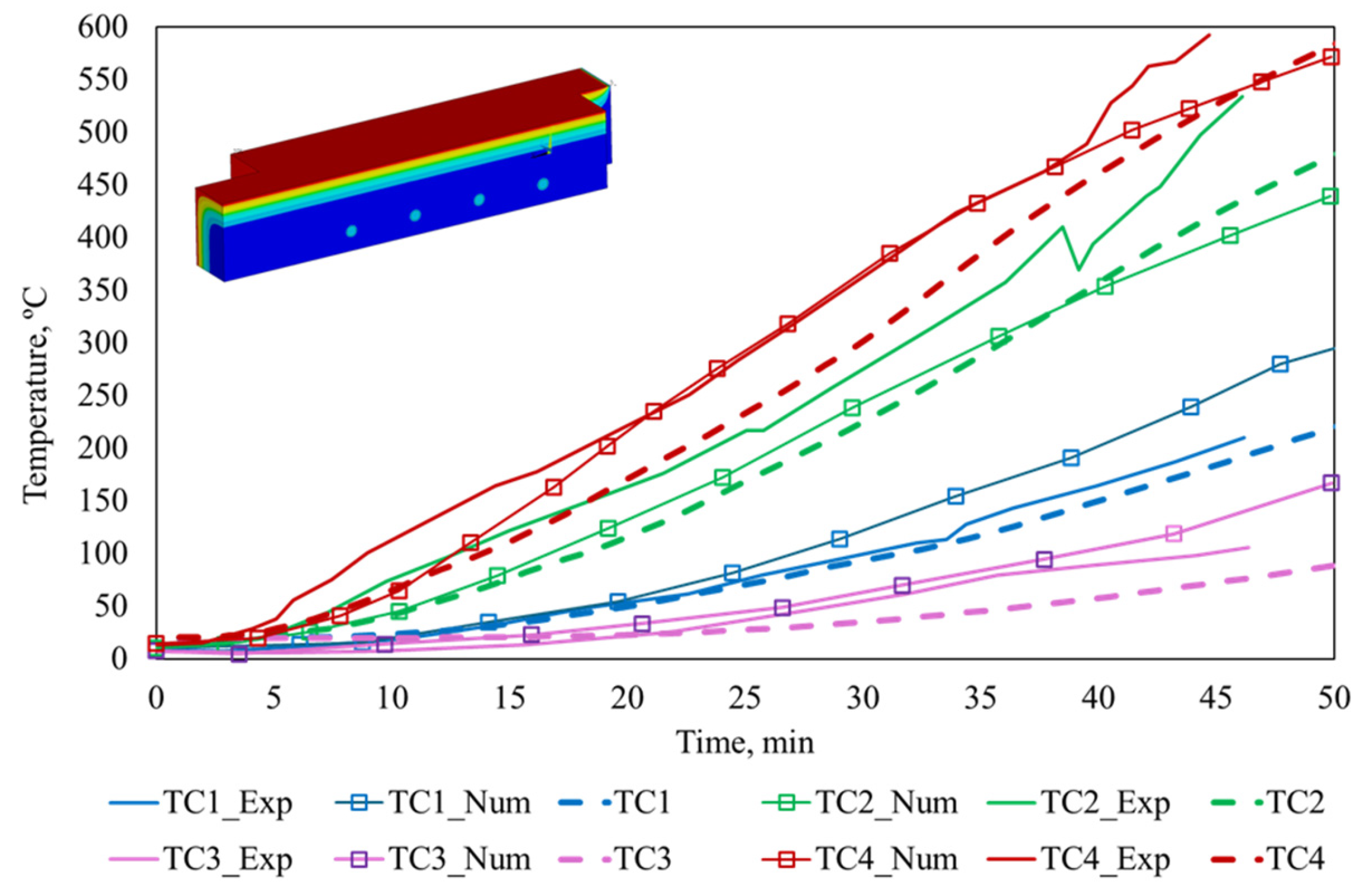
Different studies using this computational methodology have already been used in other works by the author, even in initial experimental tests for temperature and char layer calculation at 300 °C [7,17,24]. For example, in the graph of Figure 7, it is possible to verify the comparison between the proposed numerical procedure and the tests from experimental and numerical results given by Audebert et al. [25].
This is one of the validations with the proposed thermal model. A thermal numerical comparison (TCi) was realised between the same geometric connection with the material properties according to the “Connection B_2003” from [25] under fire conditions. The results comparisons are between the experimental results (TCi_Exp, in four thermocouples placed inside the wood connection) and the numerical (TCi_Num) results from the Msc-Marc software [25]. Until the time of fire exposure of 60 min, the calculated temperature in all four different nodal points was between 20 and 942 °C, close to the presented solution by the authors [25] of 20–911 °C.

2.4. Computational Models for Double and Single Shear Connections

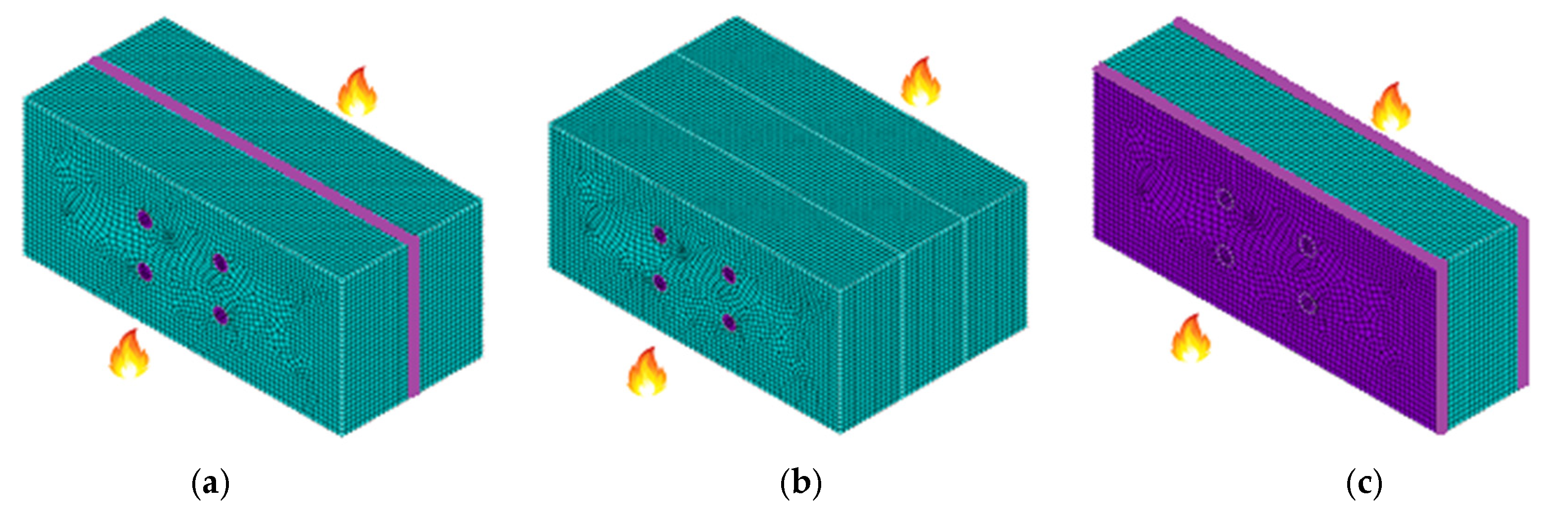
For the present study, Figure 8 and Figure 9 represent three chosen models and the applied mesh for each type of shear connection. The mesh size was calculated by observing the lower dimension in the connection dimensions—that is, the steel plate material—adjusted to 3 mm in the finite element length and the same length throughout all the meshes. The material properties for wood and steel are characterised in two colours: blue and purple, respectively. A total of 18 computational connections were reproduced using the three chosen glulam woods. The program allows us to calculate the temperature history in the wood elements and through the dowel length, verifying the influence of the steel material around the wood elements.

3. Results and Discussion

Figure 10 and Figure 11 present the thermal results. Different nodal points are considered for analysis through 1800 s of fire exposure. The results are represented for all the connections in the study and as a function of wood density.
In double shear connections, points Ki_a are located in the middle of the wooden component for A and B connections and in the interface for connection C. Points Ki_b, for connection A, are located between the interface of the steel plate and the wood component and in connections C and D in the middle of the wooden members. The nodal position K1 has the highest temperature, representing the temperature in the steel dowels, which is a good conductor of heat. In nodal position K2 inside the wood element, the temperature decreases. The temperature in connection with high-density wood material is lower in comparison. Steel-to-timber with a steel plate of any thickness as the central member always has a lower temperature, and the chosen nodal points are maintained below the target temperature of 300 °C, where the charring effect happens in the wood material, representing the most fire-resistant connection.
In single shear connections, points Ki are on the boundary of the steel plate and the wood element for connections A and B, and in the interface between the two wooden components for connection C. The nodal position K3 represents the temperature in the steel dowels. Nodal positions K2 and K1 are points internal to the wood element. The temperature in connections that are steel-to-timber with a thick steel plate and in steel-to-timber with a thin steel plate always remain high and pass the 300 °C mark early, when compared with timber-to-timber connections. The plate steel material is a good heat conductor, imposing an indirect heat effect simultaneously on the wood material in contact.
Nodal points K2 and K3 receive heat from the dowel and steel plate neighbouring the wood, and the temperature increases.
In all curves, in both connection types, there is an analogous trend for the identical points of analysis between the three density materials. GL20h wood has the highest temperature throughout all fire exposure, followed by the connection with GL24h wood, and finally the connection with GL32h wood.
Figure 12 and Figure 13 present the thermal results in the length of the dowel at 1800 s of fire exposure. The temperature is presented across the dowel dimension inside the cross-section in each studied connection. The main objective is to identify the difference involving the external lateral subjected to fire and the inner border in contact with the wood component.
In double shear connections, the temperature in the dowels increases for steel-to-timber with thin steel plates as the external members, due to the steel material effect. The connections with members in the wood allow more protection inside the dowels. The temperature decreases more than two times comparatively.
In single shear connections, the temperature in the dowels, for connections with side members in steel, is higher than seen previously, due to the steel material effect. In timber-to-timber connections, the temperatures maintain lower values of heating. The temperature along the dowels is constant, with the maximum found externally where the fire is imposed.
Figure 14 and Figure 15 present the post-processing of temperatures for a cross-section in each connection at 1800 s of fire exposure, as represented in the models in Figure 11 and Figure 12.
Higher temperatures were obtained in steel-to-timber with thin steel plates as the external members, where all the connections reached the threshold of 300 °C. In the other connections, there is part of the intact wood inside the connection.
The timber-to-timber connection maintains lower temperatures inside. For the others with an external steel plate, the temperatures are very similar, and the wood members, in this instance, have no thermal resistance.

4. Conclusions

A process with all theoretical and easy equations was obtainable to evaluate connections in double or single shear for any applied tensile load. The quantity of fasteners increases with the load, for standards at the ambient temperature. A lower dowel diameter has a more noticeable effect on the number of dowels. The mechanical influence due to the strength of the material is not important, but wood density can affect thermal behaviour. Given the numerical results, it can be determined that in connection with GL20h wood, material temperatures have higher values compared to the timber connections of GL32h; inside the wood element, the temperature remains lower; the steel dowels and steel plates affect the heat formed through the wood element and stay at elevated temperatures.
The calculation of temperatures in connection with both materials (wood and steel) under fire exposure for 1800 s allows us to conclude the following results:
-
For double shear connections, the temperature varies between 20 and 830 °C for steel-to-timber with a steel plate of any thickness as the central member and timber-to-timber; while for steel-to-timber with thin steel plates as the external members, it varies between 750 and 830 °C.
-
For single shear connections, the temperature varies between 623 and 840 °C for steel-to-timber with a thick steel plate, 765 and 840 °C for steel-to-timber with a thin plate, and 50 and 830 °C for timber-to-timber.
Temperature in relation to dowel dimension, for the same fire exposure, has the following observations:
-
For double shear connections, the temperature varies between 450 and 250 °C for steel-to-timber with a steel plate of any thickness as the central member and between 550 and 350 °C for timber-to-timber; while for steel-to-timber with thin plates as the external members, it is almost constant at 800 °C.
-
For single shear connections for steel-to-timber with a thick plate and for steel-to-timber with a thin plate, both in steel, it is almost constant at 750–800 °C; it is between 550 and 650 °C for timber-to-timber.
Elevated temperatures significantly reduce the load capacity and alter the failure mechanisms of connections due to changes in material ductility, strength, and deformation behaviour.
The comparison of the results between the types of connections showed that the steel-to-timber double shear connection, with a steel plate of any thickness as the central element and denser wood, presents the best mechanical and fire resistance. This type of connection also features the lowest temperatures in the wood components and along with the length of the dowel. Design recommendations depend on the material, connection type, and specific application. The design of connections should follow established codes, but engineers should also be aware of their conservative nature, especially when using new materials or manufacturing methods. For non-standard connections, advanced calculation methodologies based on computational models will be essential. Also, all the latest research published will be useful for optimal safety and efficiency and needs to be applied.
As a plan for future work, it would be noteworthy to continue to perform additional numerical models by changing other geometric parameters. Also, given the requirement to find options for the application of these elements in building construction so that they meet safety standards, particularly in circumstances of fire, it is essential to continue the study of protected connections. These numerical models are more helpful for improving the knowledge of the behaviour of connections under fire exposure, in comparison to the theoretical method. Furthermore, the researcher of this work is developing thermomechanical analyses of the connections, aiming to obtain the fire resistance load, and will produce additional results for future discussion.

Funding

This research received no external funding.

Institutional Review Board Statement

Not applicable.

Informed Consent Statement

Not applicable.

Data Availability Statement

The original contributions presented in the study are included in the article; further inquiries can be directed to the corresponding author.

Conflicts of Interest

The authors declare no conflicts of interest.

References

  1. Nguyen, M.; Ouldboukhitine, S.; Durif, S.; Saulnier, V.; Bouchair, A. Passive fire protection of steel profiles using wood. Eng. Struct. 2023, 275 Pt A, 115274. [Google Scholar] [CrossRef]
  2. Richardson, L.; Batista, M. Fire resistance of timber decking for heavy timber construction. Fire Mater. 2001, 25, 21–29. [Google Scholar] [CrossRef]
  3. Kia, L.; Valipour, H.R. Composite timber-steel encased columns subjected to concentric loading. Eng Struct. 2021, 232, 111825. [Google Scholar] [CrossRef]
  4. Maraveas, C.; Miamis, K.; Matthaiou, C.E. Performance of Timber Connections Exposed to Fire: A Review. Fire Technol. 2013, 51, 1401–1432. [Google Scholar] [CrossRef]
  5. Li, X.; Yue, K.; Zhu, L.; Lv, C.; Wu, J.; Wu, P.; Li, Q.; Xu, C.; Sun, K. Relationships between wood properties and fire performance of glulam columns made from six wood species commonly used in China. Case Stud. Therm. Eng. 2024, 54, 104029. [Google Scholar] [CrossRef]
  6. Bartlett, A.; Hadden, R.; Bisby, L.A. A Review of Factors Affecting the Burning Behaviour of Wood for Application to Tall Timber Construction. Fire Technol. 2018, 55, 1–49. [Google Scholar] [CrossRef]
  7. Fonseca, E.M.M.; Leite, P.A.; Silva, L. Wood Connections Under Fire Conditions Protected with Gypsum Plasterboard Types A and F. In Advances in Fire Safety Engineering; Springer Nature: Cham, Switzerland, 2020; Chapter 7; Volume 1, pp. 93–106. [Google Scholar] [CrossRef]
  8. EN1995-1-2:2004; Eurocode 5. Design of timber structures. Part 1-2: General Structural Fire Design. European Union: Brussels, Belgium, 2004.
  9. Fonseca, E.M.M. Steel-to-Timber and Timber-to-Timber Simple Shear Connections. WSEAS Trans. Appl. Theor. Mech. 2024, 19, 156–160. [Google Scholar] [CrossRef]
  10. Just, A.; Schmid, J.; König, J. Gypsum Plasterboards Used as Fire Protection—Analysis of a Database; SP Report; SP Technical Research Institute of Sweden: Sweden, Stockholm, 2010. [Google Scholar]
  11. Fonseca, E.M.M. Brief overview of the thermal and mechanical properties of wood, steel, and gypsum board for structural connections. GeoStruct Innov. 2024, 2, 77–89. [Google Scholar] [CrossRef]
  12. EN 1993-1-2:2005; Eurocode 3. Design of Steel Structures. Part 1-2: General Rules—Structural Fire Design. European Union: Brussels, Belgium, 2005.
  13. Audebert, M.; Dhima, D.; Taazount, M.; Bouchaïr, A. Behavior of dowelled and bolted steel-to-timber connections exposed to fire. Eng. Struct. 2022, 39, 116–125. [Google Scholar] [CrossRef]
  14. Schenk, M.; Ohm, J.; Winter, S. Eurocode 5: From Mandate to Second Generation—Review, Insight and Outlook. In Proceedings of the World Conference on Timber Engineering, Brisbane, Australia, 22–26 June 2025; pp. 36–45. [Google Scholar] [CrossRef]
  15. Palma, P.; Munch-Andersen, J.; Dietsch, P. Updating Eurocode 5—Design Guidance for Increasing the Robustness of Timber Structures. In Proceedings of the World Conference on Timber Engineering, Oslo, Norway, 19–22 June 2023; pp. 3054–3061. [Google Scholar] [CrossRef]
  16. Miguel, O.; Fonseca, E.M.M.; Pereira, D. Fire Resistance in Screwed and Hollow Core Wooden Elements Filled with Insulating Material. Fire 2014, 8, 288. [Google Scholar] [CrossRef]
  17. Fonseca, E.M.M.; Gomes, C. FEM Analysis of 3D Timber Connections Subjected to Fire: The Effect of Using Different Densities of Wood Combined with Steel. Fire 2023, 6, 193. [Google Scholar] [CrossRef]
  18. EN 1995-1-1:2004; Eurocode 5. Design of Timber Structures. Part 1-1: General—Common Rules and Rules for Buildings. European Union: Brussels, Belgium, 2004.
  19. EN 1993-1-1:2005; Eurocode 3: Design of Steel Structures. Part 1-1: General Rules and Rules for Buildings. European Union: Brussels, Belgium, 2005.
  20. Filippo, F.; Jan, S.; Roald, R. Load-Carrying Capacity and Stiffness of Softwood Wooden Dowel Connections. Int. J. Archit. Herit. 2018, 14, 376–397. [Google Scholar] [CrossRef]
  21. Ramage, M.H.; Burridge, H.; Busse-Wicher, M.; Fereday, G.; Reynolds, T.; Shah, D.U.; Wu, G.; Yu, L.; Fleming, P.; Densley-Tingley, D.; et al. The wood from the trees: The use of timber in construction. Renew. Sustain. Energy Rev. 2017, 68 Pt 1, 333–359. [Google Scholar] [CrossRef]
  22. EN1991-1-2:2003; Eurocode 1. Actions on Structures. Part 1-2: General Actions—Actions on Structures Exposed to Fire. European Union: Brussels, Belgium, 2003.
  23. Rossi, S.; Crocetti, R.; Honfi, D.; Hansson, E. Load-bearing capacity of ductile multiple shear steel-to-timber connections. In Proceedings of the WCTE 2016 World Conference on Timber Engineering, Vienna, Austria, 22–25 August 2016. [Google Scholar]
  24. Fonseca, E.M.M.; Barreira, L. Experimental and Numerical Method for Determining Wood Char-Layer at High Temperatures due an Anaerobic Heating. Int. J. Saf. Secur. Eng. 2011, 1, 65–76. [Google Scholar] [CrossRef]
  25. Audebert, M.; Dhima, D.; Taazount, M.; Bouchaır, A. Thermo-mechanical behaviour of timber-to-timber connections exposed to fire. Fire Saf. J. 2013, 56, 52–64. [Google Scholar] [CrossRef]
Figure 1. Time–fire curve and thermal material properties of wood and steel.
Fire 08 00310 g001
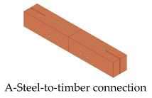
Figure 2. Number of dowels in double shear connection for: (a) A-steel-to-timber with a steel plate of any thickness as the central member, (b) B-timber-to-timber, (c) C-steel-to-timber with thin steel plates as the external members.
Fire 08 00310 g002
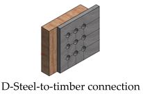
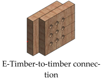
Figure 3. Number of dowels in single shear connection in: (a) D-i)-steel-to-timber with a thick steel plate, (b) D-ii)-steel-to-timber with a thin steel plate, (c) E-timber-to-timber.
Fire 08 00310 g003
Figure 4. Spacing or edge/end distance between dowels in double shear connections in A-steel-to-timber with a steel plate of any thickness as the central member, B-timber-to-timber, and C-steel-to-timber with thin steel plates as the external members, mm.
Fire 08 00310 g004
Figure 5. Spacing or edge/end distance between dowels in single shear connections in D-i)-steel-to-timber with a thick steel plate, D-ii)-steel-to-timber with a thin steel plate, and E-timber-to-timber, mm.
Fire 08 00310 g005
Figure 6. Thermal analysis, flowchart.
Fire 08 00310 g006
Figure 7. Thermal comparison between the developed and the referenced model. Detailed information is as follows: TC1_Exp and TC2_Exp are thermocouples placed inside the wood connection [25], and TC3_Exp and TC4_Exp are in the lateral mid-height members [25]; TC1_Num, TC2_Num, TC3_Num, and TC4_Num are numerical positions from reference [25]; TC1, TC2, TC3, and TC4 are numerical positions from the developed computational model.
Fire 08 00310 g007
Figure 8. Representative meshes for double shear connections: (a) A-steel-to-timber with a steel plate of any thickness as the central member, (b) B-timber-to-timber, (c) C-steel-to-timber with thin steel plates as the external members. The blue colour represents the wood element; the violet colour represents the steel plate and dowels.
Fire 08 00310 g008
Figure 9. Representative meshes for single shear connections: (a) D-i)-steel-to-timber with a thick steel plate, (b) D-ii)-steel-to-timber with a thin steel plate, (c) C-timber-to-timber. The blue colour represents the wood element; the violet colour represents the steel plate and dowels.
Fire 08 00310 g009
Figure 10. Temperature–time history for double shear connections: (a) A-steel-to-timber with a steel plate of any thickness as the central member, (b) B-timber-to-timber, (c) C-steel-to-timber with thin steel plates as the external members.
Fire 08 00310 g010
Figure 11. Temperature–time history for single shear connections: (a) D-i)-steel-to-timber with a thick steel plate, (b) D-ii)-steel-to-timber with a thin steel plate, (c) E-timber-to-timber.
Fire 08 00310 g011
Figure 12. Temperature through the dowel length at 1800 s for double shear connections: (a) A-steel-to-timber with a steel plate of any thickness as the central member, (b) B-timber-to-timber, (c) C-steel-to-timber with thin steel plates as the external members.
Fire 08 00310 g012
Figure 13. Temperature through the dowel length at 1800 s for single shear connections: (a) D-i)-steel-to-timber with a thick steel plate, (b) D-ii)-steel-to-timber with a thin steel plate, (c) E-timber-to-timber.
Fire 08 00310 g013
Figure 14. Temperature at 1800 s for double shear connections: (a) A-steel-to-timber with a steel plate of any thickness as the central member, (b) B-timber-to-timber, (c) C-steel-to-timber with thin steel plates as the external members.
Fire 08 00310 g014
Figure 15. Temperature at 1800 s for single shear connections: (a) D-i)-steel-to-timber with a thick steel plate, (b) D-ii)-steel-to-timber with a thin steel plate, (c) E-timber-to-timber.
Fire 08 00310 g015
Table 1. Easy equations for connections in double shear.
Fire 08 00310 i001With a steel plate of any thickness as the central member
F v , R k = m i n f h , 1 , k   t 1   d           ( a ) f h , 1 , k   t 1 d 2 + 4   M y , R k f h , R k   d   t 1 2 1 +   F a x , R k 4     ( b ) 2.3     M y , R k   f h , 1 , k   d   +   F a x , R k 4     ( c )
Fire 08 00310 i002
Fire 08 00310 i003 F v , R k = m i n f h , 1 , k   t 1   d       ( a ) 0.5   f h , 2 , k   t 2   d       ( b ) 1.05   f h , 1 , k   t 1   d 2 + β   2 β 1 + β + 4   β 2 + β M y , R k f h , 1 , k   d   t 1 2 β +   F a x , R k 4       ( c ) 1.15 2 β 1 + β 2   M y , R k   f h , 1 , k   d +   F a x , R k 4         ( d )
Fire 08 00310 i004
Table 2. Easy equations for connections in single shear.
Fire 08 00310 i005i) With a thick steel plate in single shear
F v , R k = m i n f h , 1 , k   t 1   d 2 + 4   M y , R k f h , 1 , k   d   t 1 2 1 +   F a x , R k 4       ( a ) 2.3     M y , R k   f h , 1 , k   d   +   F a x , R k 4           ( b ) f h , 1 , k   t 1   d       ( c )
Fire 08 00310 i006
ii) With a thin steel plate in single shear
F v , R k = m i n 0.4   f h , 1 , k   t 1   d         ( a )   1.15   2   M y , R k   f h , 1 , k   d +   F a x , R k 4           ( b )
Fire 08 00310 i007
Fire 08 00310 i008 F v , R k = m i n   f h , 1 , k   t 1   d         ( a )     f h , 2 , k   t 2   d         ( b )   f h , 1 , k   t 1   d 1 + β   β + 2 β 2 1 + t 2 t 1 + t 2 t 1 2 + β 3 t 2 t 1 2 β 1 + t 2 t 1 +   F a x , R k 4       ( c ) 1.05   f h , 1 , k   t 1   d 2 + β   2 β 1 + β + 4   β 2 + β M y , R k f h , 1 , k   d   t 1 2 β +   F a x , R k 4       ( d ) 1.05   f h , 1 , k   t 2   d 1 + 2 β   2 β 2 1 + β + 4   β 1 + 2   β M y , R k f h , 1 , k   d   t 2 2 β +   F a x , R k 4       ( e ) 1.15 2 β 1 + β   2   M y , R k   f h , 1 , k   d +   F a x , R k 4           ( f )
Fire 08 00310 i009
Table 3. Equations to determine the spacing and edge/end distance in dowelled connections.
Spacing and Edge/End DistancesMinimum Spacing or Edge/End Distance
a1 (parallel to grain)(3 + 2 + |cos α|) d
a2 (perpendicular to grain)3 d
a3,t (loaded end)Max (7 d; 80 mm)
a4,c (unloaded edge)3 d
Table 4. The design characteristic load-carrying capacity in the selected connections, Fv, rd, and kN.
Connection TypeGL20hGL24hGL32h
d = 8 mmd = 10 mmd = 8 mmd = 10 mmd = 8 mmd = 10 mm
A3.1874.1803.5484.6243.9825.157
B2.5443.4242.7103.8012.8974.251
C2.3133.4192.4613.6382.6313.889
D-i)2.1793.2562.3873.5662.7564.118
D-ii)2.5443.1462.7103.5712.8974.081
E2.5443.7592.7104.0052.8974.282
Disclaimer/Publisher’s Note: The statements, opinions and data contained in all publications are solely those of the individual author(s) and contributor(s) and not of MDPI and/or the editor(s). MDPI and/or the editor(s) disclaim responsibility for any injury to people or property resulting from any ideas, methods, instructions or products referred to in the content.