Article

Experimental Study on Effects of Lateral Spacing on Flame Propagation over Solid Fuel Matrix

1
Jiangsu College of Safety Technology, Xuzhou 221000, China
2
School of Safety Engineering, China University of Mining and Technology, Xuzhou 221116, China
*
Author to whom correspondence should be addressed.
Fire 2025, 8(7), 284; https://doi.org/10.3390/fire8070284
Submission received: 18 June 2025 / Revised: 16 July 2025 / Accepted: 18 July 2025 / Published: 20 July 2025

Abstract

The increasing complexity of urban structures has significantly elevated the risk and severity of façade fires in high-rise buildings. Unlike traditional models assuming continuous fuel beds, real-world fire scenarios often involve discrete combustible materials arranged in discrete fuel matrices. This study presents a systematic investigation into the influence of lateral spacing on vertical flame propagation behavior. Laboratory-scale experiments were conducted using vertically oriented polymethyl methacrylate (PMMA) fuel arrays under nine different spacing configurations. Results reveal that lateral spacing plays a critical role in determining flame spread paths and intensities. Specifically, with a vertical spacing fixed at 8 cm, a lateral spacing of 10 mm resulted in rapid flame growth, reaching a peak flame height of approximately 96.5 cm within 450 s after ignition. In contrast, increasing the lateral spacing to 15 mm significantly slowed flame development, achieving a peak flame height of just under 90 cm at approximately 600 s. This notable transition in flame dynamics is closely associated with the critical thermal boundary layer thickness (~11.5 mm). Additionally, at 10 mm spacing, a chimney-like effect was observed, enhancing upward air entrainment and resulting in intensified combustion. These findings reveal the coupled influence of geometric configuration and heat transfer mechanisms on façade flame propagation. The insights gained provide guidance for cladding system design, suggesting that increasing lateral separation between combustible elements may be an effective strategy to limit flame spread and enhance fire safety performance in buildings.

1. Introduction

With the acceleration of urbanization, modern high-rise buildings featuring increasingly complex architectural designs have become prevalent. These structures frequently prioritize aesthetic appeal and innovation in their external façades, utilizing a variety of cladding materials. However, the diverse nature of these materials can heighten fire risks, making façade fires a significant global safety concern [1]. The building façade, often described as the “skin” of contemporary architecture, typically includes insulating layers, decorative elements, and other components that together form a natural fuel matrix. This fuel matrix can either initiate or facilitate fire spread into the building interior, significantly increasing the severity of fires [2].
Advances in understanding solid fuel flame spread [3,4,5,6,7] have highlighted that fuels in realistic fire scenarios are typically arranged discontinuously [8]. The gaps between fuels provide additional air pathways, significantly influencing heat and mass transfer, and consequently altering the fire hazards. Therefore, studying flame propagation behaviors on discontinuous fuel matrices has become increasingly critical. Early research [9,10,11] frequently employed simplified “matchstick” models to investigate various factors influencing flame spread, such as fuel spacing, ambient wind, and slope angles. Miller and Gollner [12] introduced the “fuel coverage ratio” concept through experiments involving vertical cast polymethyl methacrylate (PMMA) plates, demonstrating that flame spread rates initially increase and subsequently decrease with rising fuel coverage ratio, identifying approximately 30% as a critical threshold.
Subsequent studies by researchers such as Xu et al. [13] expanded on this methodology, confirming the critical fuel coverage ratio over broader spacing ranges and developing analytical models based on heat transfer. Experiments conducted by Cui et al. [14] revealed a trend of increasing flame spread velocity followed by a decrease as air gaps enlarged. Wolff et al. [15] systematically investigated the promoting effect of counterflow (i.e., external wind) velocity on flame spread rate. Following this, numerical simulations by Luo et al. [16] further examined the interaction between fuel gap length and counterflow velocity. Giovanni et al. [17] studied flame propagation in wooden fuel arrays under forced airflow conditions, classifying fire behavior into continuous, discrete, and quenching states. Research by Bu et al. [18], employing birch sticks as fuel, provided deeper insights into the roles of inclination and heat transfer mechanisms, leading to the establishment of a mass-loss prediction model.
Existing research [19,20,21,22] has provided substantial theoretical guidance for the implementation of vertical fire barriers. However, Zhang et al. [23] noted that inadequate vertical spacing could fail to prevent fire spread effectively and may even enhance fire growth due to induced air entrainment. In contrast to extensive studies on vertical spacing effects, systematic investigations regarding lateral spacing within façade fuel matrices remain limited. In real fire scenarios, as illustrated in Figure 1, the distribution of combustibles tends to form a two-dimensional fuel matrix, rather than the tree-like fuel element arrays commonly adopted in previous studies on forest fire investigations [24,25,26,27]. In contrast, our study examines compact fuel arrays that simulate realistic building façade configurations. Moreover, the depicted fire accident suggests that laterally spaced fire barriers may offer improved effectiveness in impeding flame spread across the façade compared with relying solely on vertical separations. Therefore, exploring the influence of lateral spacing is particularly important for advancing façade fire protection strategies.
To bridge this research gap, this study conducts scaled-down fire experiments within a controlled laboratory environment, utilizing experimental setups that simulate building façades. The research systematically investigates the influence of lateral spacing on flame propagation across fuel matrices by varying the spacing of combustible materials and meticulously monitoring key fire characteristics, including flame height, burning rate, and flame spread pathways. Qualitative and quantitative analyses of these parameters are conducted to reveal fundamental mechanisms and rules governing façade fire propagation, providing scientific insights to enhance façade design and optimize fire prevention strategies.

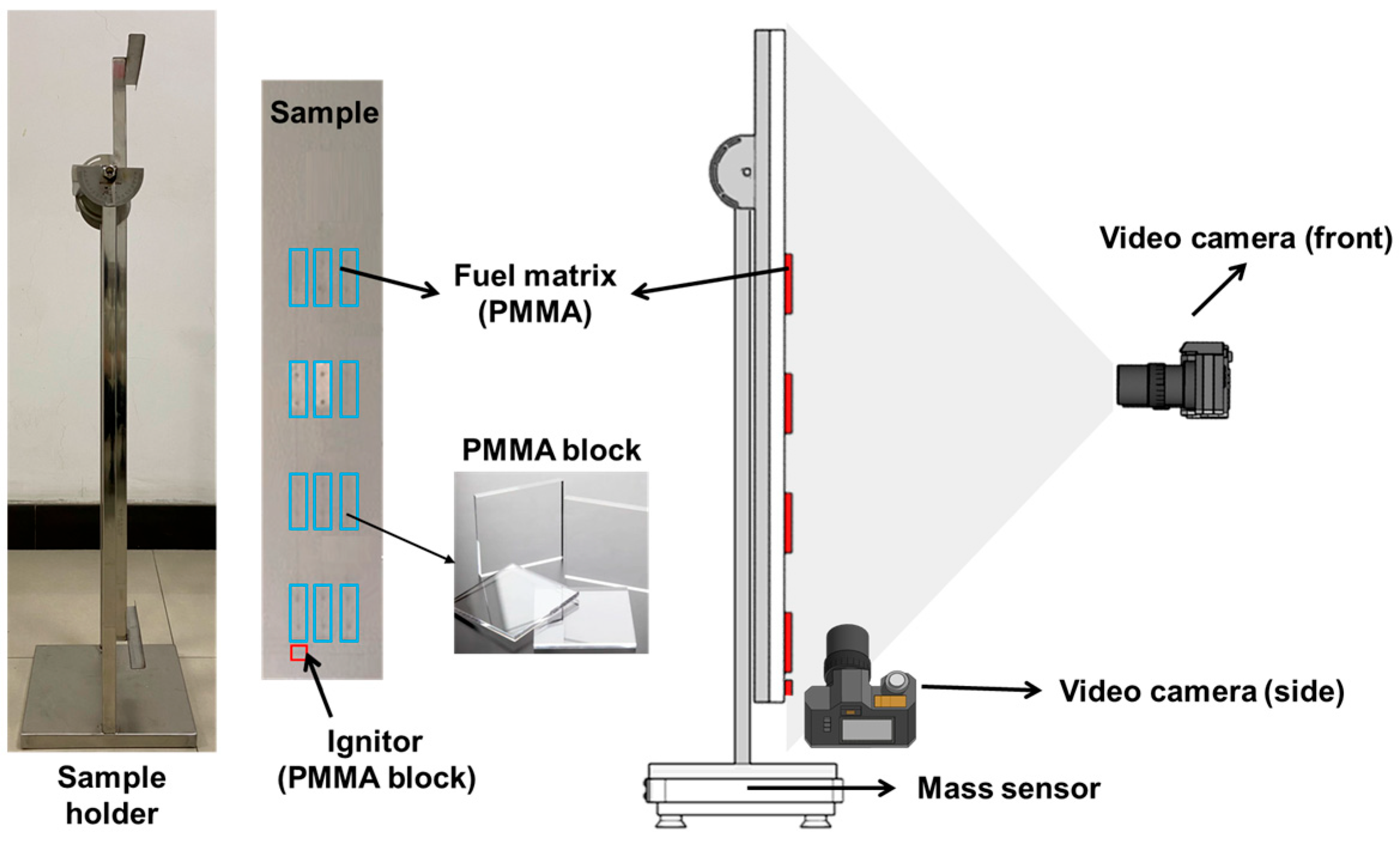
2. Materials and Methods

In this study, cast polymethyl methacrylate (PMMA) was utilized as the test material. The principal advantages of PMMA include (1) ease of procurement, processing, and manipulation, enabling precise control over shape and dimensions, (2) stable combustion characteristics and relatively simple combustion products, facilitating accurate and reproducible experimental results, and (3) extensive prior use in fundamental fire science research [28,29,30,31], allowing the results obtained herein to be conveniently benchmarked against previously published data. The PMMA materials used in the experiments were supplied by Jingjian Co., Ltd., Shanghai, China and this batch of PMMA blocks possesses a solid-phase density of approximately 1190 kg/m3, thermal conductivity of 0.2 ± 0.01 W/(m·K), and an effective heat of combustion of around 24.9 MJ/kg.
The experimental setup used to investigate concurrent flame spread over discrete PMMA fuel surfaces is illustrated in Figure 2. It comprises three main components as follows: a PMMA fuel matrix module, a vertical sample holder, and a steel base. The fuel matrix consists of multiple standardized PMMA blocks (8 cm × 3 cm × 1 cm) mounted on a fire-resistant alumina-silicate ceramic backing plate (120 cm × 20 cm × 2 cm). Positioned at the bottom-left corner of the PMMA array, 1 cm below the first PMMA block, was an ignition block with dimensions identical in width and thickness to the fuel panels but with a length of 1 cm. This ignition block was intended to uniformly preheat the PMMA fuel matrix above and minimize interference from the ignition process on subsequent flame spread dynamics.
The entire assembly was mounted on a load cell (Siemens WL230 BB-S SA; 10 kg capacity, 0.1 g resolution) to measure mass loss during combustion. Thermal insulation was applied to shield the sensor from radiant heat. Mass data collected during experiments were subjected to first-order differentiation to derive corresponding mass loss rates, equivalent to burning rates. Following the methodology suggested by Morrisset et al. [32], a second-order, 20-point Savitzky–Golay filter was applied to smooth the mass loss data. This approach reduced data noise while effectively preserving the intrinsic trends of the original measurements.
Two high-definition video cameras (model SONY FDR-AX60 4K, equipped with 26.8 mm wide-angle Zeiss lenses) were positioned at the front and side of the fuel matrix to record the evolution of flame morphology. The captured videos were directly utilized to qualitatively describe flame spread processes. Furthermore, quantitative flame parameters, such as flame height and width, were obtained using the OpenCV image processing toolkit [33]. Video frames were extracted and converted to grayscale images, after which adaptive RGB thresholding was employed to binarize the images, thereby yielding sharply defined black-and-white representations of the flame shapes [34].
In this study, nine distinct fuel matrix configurations were established to conduct burning tests. The recorded data from the aforementioned apparatus were employed to analyze the effects of lateral spacing on key parameters of flame spread over a discrete solid fuel matrix, such as flame height, flame spread trajectory, and burning rate. Details of the experimental conditions are summarized in Table 1.
To ensure the accuracy and reliability of the results, each test scenario was conducted at least three times. The analyses presented herein are based on the average values obtained from the repeated experiments.

3. Results

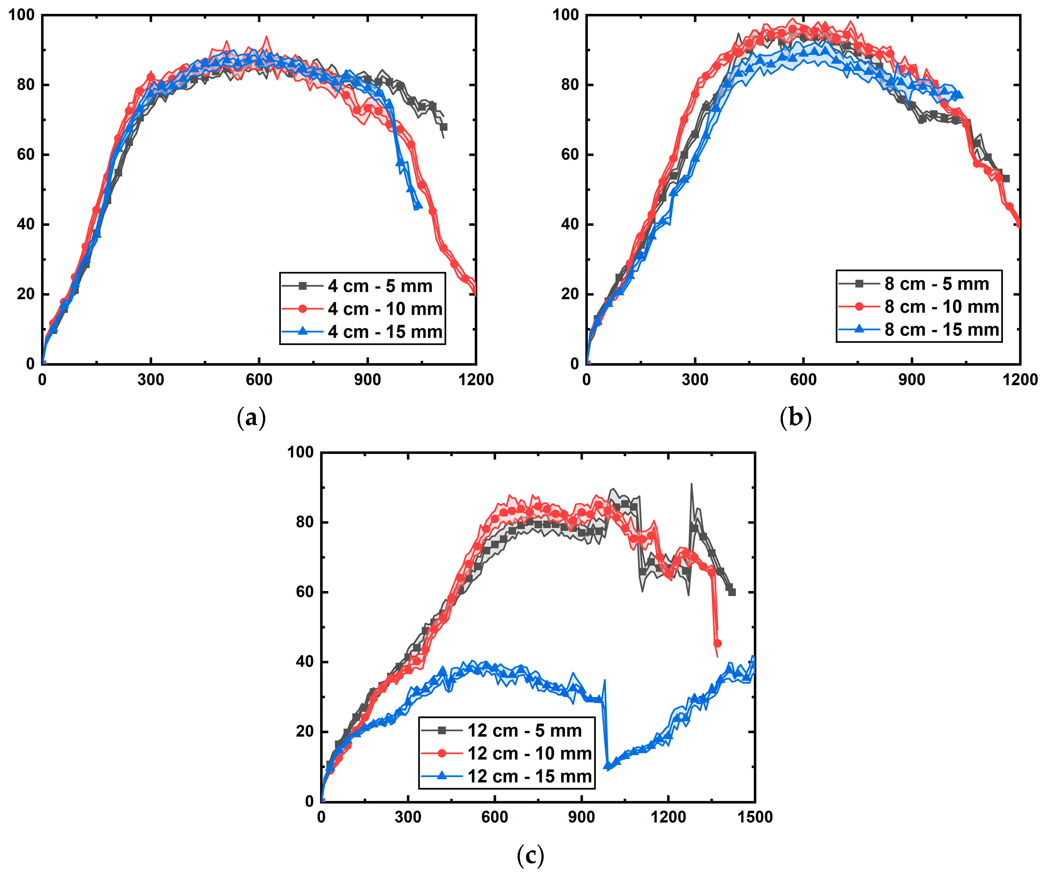
3.1. Flame Heights over Fuel Matrix

Flame height in fuel matrices not only reflects the scale and energy release of a fire but also directly impacts critical factors such as heat radiation, combustion product emissions, and gas flow dynamics. Hence, accurate measurement and understanding of flame height are essential for effectively managing fire risks. In this study, flame height is defined as the vertical linear distance from the base to the tip of the flame, determined accurately using the image recognition and processing methods mentioned in Section 2. Figure 3 illustrates the temporal evolution of flame height for various fuel matrix configurations, labeled in the format “vertical spacing–lateral spacing” (e.g., “4 cm–5 mm” indicates a fuel matrix with 4 cm vertical spacing and 5 mm lateral spacing).
As illustrated in Figure 3a, under a vertical spacing of 4 cm, the flame height curves for three different lateral spacings (5 mm, 10 mm, and 15 mm) exhibited highly similar trends. Specifically, the flame height rapidly increased within the first 300 s, reaching a plateau phase with a peak flame height of approximately 83 cm, and subsequently declined as the fuel was progressively consumed. This finding suggests that at relatively small vertical spacing, lateral spacing has a limited effect on the overall fire development.
When the vertical spacing increased to 8 cm (Figure 3b), the influence of lateral spacing began to emerge. In particular, as the lateral spacing increased from 5 mm to 15 mm, the peak flame height on the fuel matrix surface first increased and then decreased. A maximum flame height of nearly 100 cm was observed at a lateral spacing of 10 mm, while the case with 15 mm lateral spacing exhibited suppressed flame growth and a lower peak height. However, this mitigation effect remained moderate. Further, as shown in Figure 3c, when the vertical spacing reached 12 cm, the lateral spacing of 15 mm demonstrated a pronounced mitigation effect by the lateral spacing, significantly limiting flame propagation. In contrast, for lateral spacings of 5 mm and 10 mm, the mitigation effect was not evident, and the flame height evolution followed a similar trend, with only a slight difference—a marginally higher peak flame height in the 10 mm scenario compared with the 5 mm case.
Based on the above comparison, a preliminary conclusion can be reached that the flame spread process over the fuel matrix surface is primarily governed by vertical spacing, while lateral spacing plays a secondary role. Notably, only under large vertical spacing does an increase in lateral spacing induce a qualitative change in the flame propagation characteristics across the fuel matrix surface.

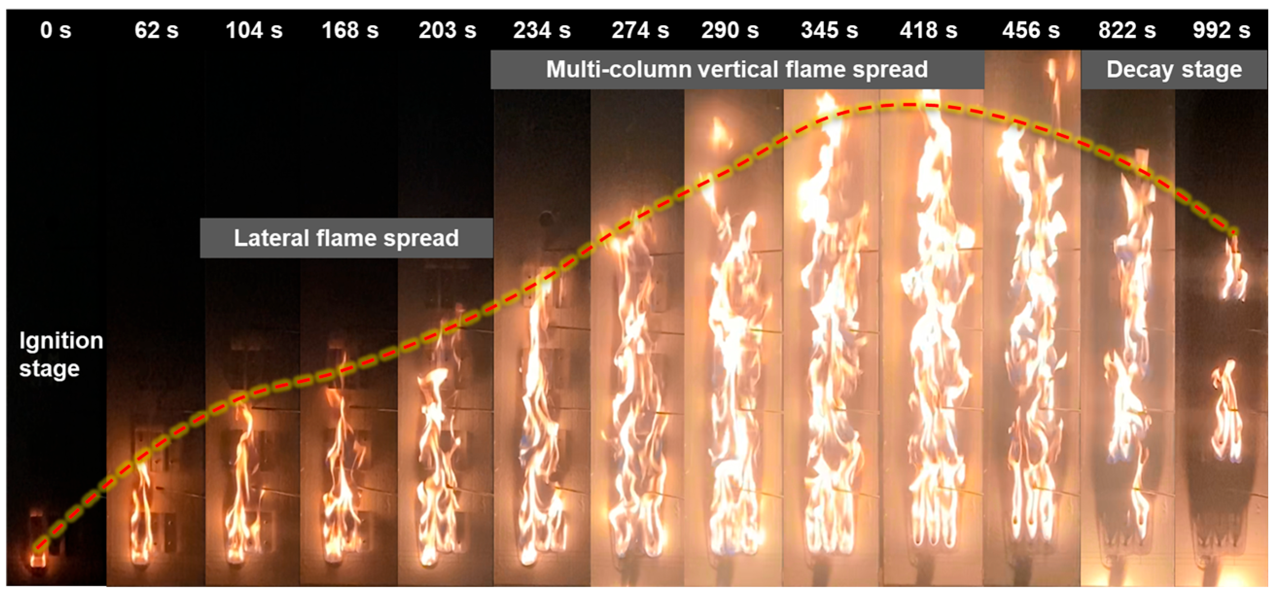
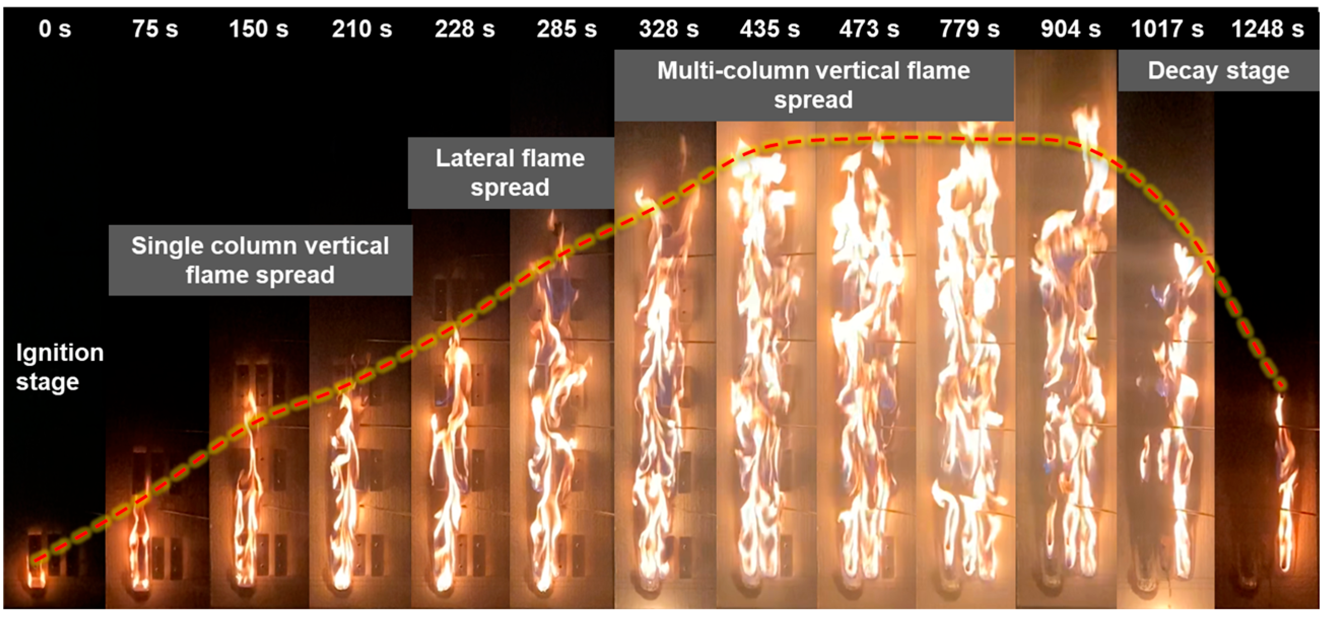
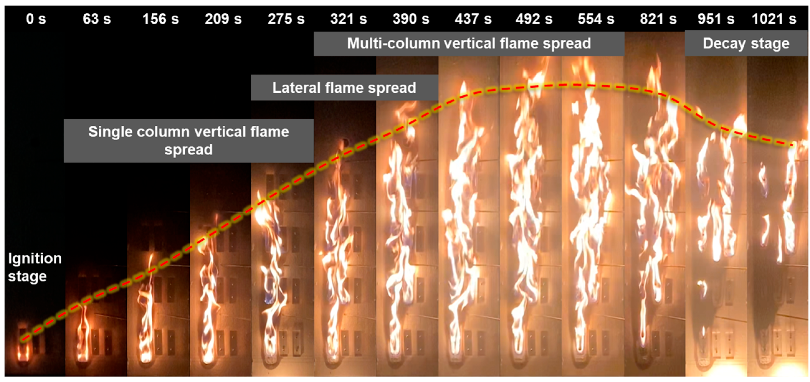
3.2. Flame Spread Paths

This subsection further presents the flame morphology observed on the surface of the fuel matrix. These images, captured by a high-definition camera positioned in front of the experimental setup, provide a direct visualization of the influence of lateral spacing on flame propagation paths. Figure 4 shows the temporal evolution of flame morphology for a fuel matrix configuration with a lateral spacing of 5 mm and a vertical spacing of 8 cm. Approximately 104 s after ignition of the bottom fuel element in the first column, the flame propagated across the 5 mm lateral spacing and ignited the bottom fuel element in the second column. Following the merging of flames from these two columns, the flame intensity increased significantly, resulting in the near-simultaneous ignition of the bottom fuel element in the third column and the second-layer element in the first column. Subsequently, the integrated flames from all three columns expanded in volume, accelerating the ignition of the upper fuel elements and forming a rapid vertical propagation across multiple columns. Specifically, the second, third, and fourth fuel layers were ignited sequentially at approximately 234 s, 274 s, and 290 s, respectively. The flame height then rapidly reached its peak, remained stable for a period, and gradually decreased as the lower fuel was consumed. These observations indicate that the small lateral spacing (5 mm) allowed the flame to readily traverse the lateral gaps, enabling early horizontal propagation followed by swift vertical spread.
As shown in Figure 5, when the lateral spacing increased to 10 mm, the expanded spacing reduced the efficiency of heat transfer between adjacent fuel elements. Flame propagation initially exhibited a predominant vertical trend, reaching the third-layer fuel element in the first column at approximately 210 s. During this vertical development, the flame intensity gradually increased. Around 228 s, the flame crossed the lateral gap and ignited the second column, marking the onset of lateral spread. The flames from the second and third columns then propagated vertically and merged with the original flame, further enhancing flame height and resulting in a rapid vertical spread across multiple columns. At approximately 473 s, the intensified flame ignited the fourth-layer fuel, reaching the peak flame height, which subsequently declined as the lower fuel layers were burned out.
For the case with a lateral spacing of 15 mm (Figure 6), the flame spread in the fuel matrix exhibited more distinct staged characteristics: initial rapid vertical flame spread, followed by gradual lateral flame spread, and eventually rapid vertical propagation across multiple columns until fuel burns out. Specifically, after igniting the bottom fuel in the first column, the flame propagated vertically, igniting the first three layers within 275 s. Lateral propagation began afterward, igniting the second-layer fuel in the second column at approximately 321 s, and the third-layer fuel in the third column at around 492 s. After the merging of flames from all three columns, the fourth-layer fuel was ignited at 554 s, corresponding to the peak flame height. Thereafter, the flame intensity gradually declined as the fuel was consumed. Notably, the first-layer fuel element in the second column remained largely unaffected throughout the combustion process, and the first and second layers in the third column also remained intact.
These experiments indicate that flame propagation typically begins in a vertical direction and, during its upward progression, initiates lateral spread. The variations in lateral spacing significantly influenced the development paths of flame propagation. Under small lateral spacing, flames can readily cross the lateral gaps and transition into global vertical spread at an early stage. With increased lateral spacing, however, sufficient flame intensity must first be developed through vertical propagation before lateral spread can occur, ultimately resulting in vertical flame propagation across the entire fuel matrix. These findings provide valuable insights into the underlying mechanisms of flame spread and offer important implications for optimizing fire management and prevention strategies.

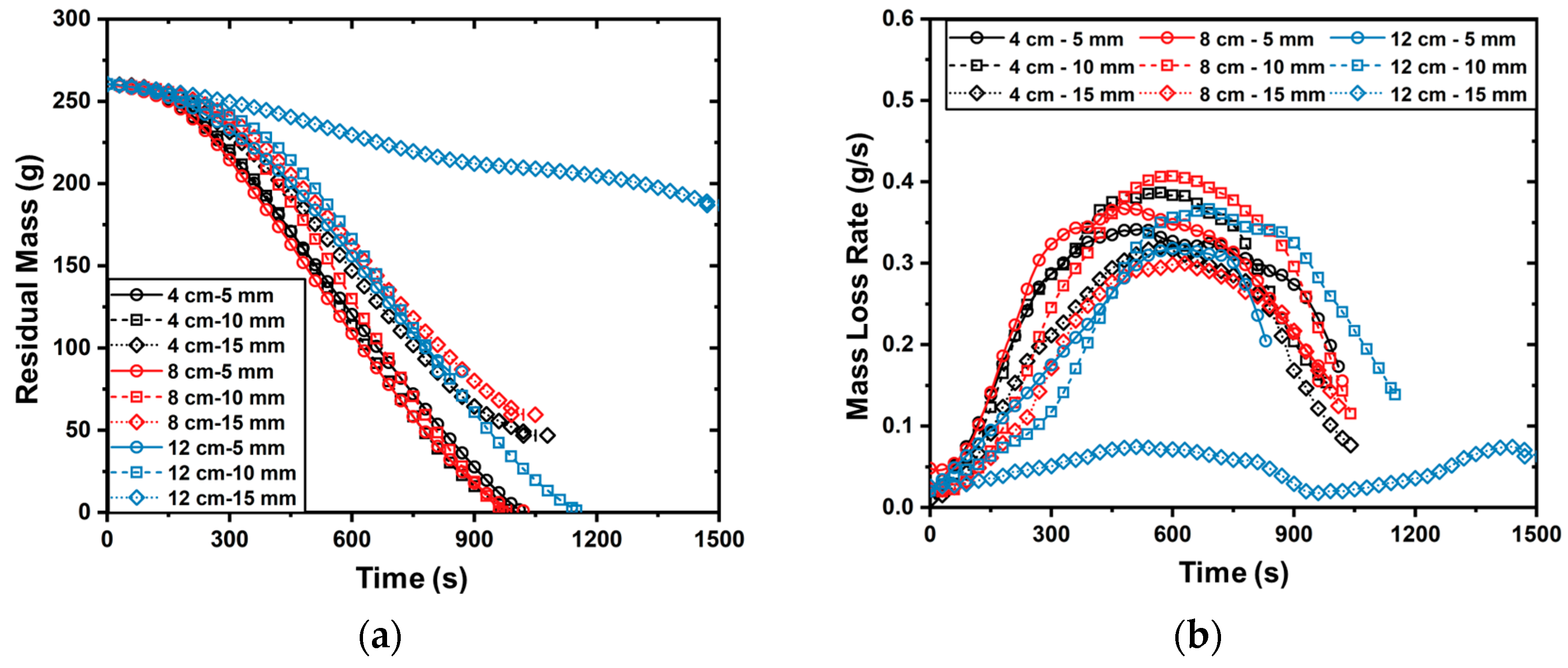
3.3. Burning Rates of Fuel Matrix

The burning rate is a key indicator for evaluating the energy release rate of solid fuels. A higher burning rate implies that the fuel can rapidly release a large amount of energy, potentially accelerating fire spread. In this study, fuel mass variations over time were recorded using a mass sensor (see Section 2). By comparing the initial mass before combustion with the residual mass after combustion, the burning rates of the fuel matrices were determined. Figure 7 presents the recorded variations in fuel mass and mass loss rate for different fuel matrix configurations. All data points shown represent the mean values obtained from repeated experiments, and the maximum variation observed across repetitions did not exceed 12.7%.
By comparing data curves of the same color, it is evident that lateral spacing has a significant effect on the burning rate of the fuel matrix. Specifically, as the lateral spacing increases, the peak burning rate first increases and then decreases. Across the three vertical spacing configurations used in the experiments, the maximum burning rate consistently occurred at a lateral spacing of 10 mm. Furthermore, comparisons of data curves with identical symbols reveal that the peak burning rate also shows a rising-then-falling trend as vertical spacing increases, which is consistent with previous experimental observations [13,28].
It is noteworthy that the influence of lateral spacing is substantially greater than that of vertical spacing. For example, when using the configuration with 5 mm lateral spacing and 4 cm vertical spacing as a reference, increasing the lateral spacing to 15 mm led to a reduction in peak mass loss rate comparable to that observed when increasing the vertical spacing from 4 cm to 12 cm under identical conditions. This result indicates that a 1 cm increase in lateral spacing yields a mitigating effect on combustion approximately equivalent to an 8 cm increase in vertical spacing. Such a strong sensitivity highlights the critical role of lateral spacing in controlling combustion intensity. Therefore, in the design of building façades, increasing the lateral spacing between combustible materials should be prioritized as an effective fire prevention strategy.

4. Discussion

Based on the experimental observations presented in Section 3, a general trend of flame propagation over the fuel matrix can be identified: flames initially propagate vertically until sufficient energy is released to ignite adjacent fuel elements, after which lateral spread commences. The presence of lateral spacing effectively reduces the heat flux transmitted from the flame to adjacent lateral fuels, thereby decelerating the propagation rate. Consequently, the initial flame needs to achieve a greater vertical scale (i.e., increased flame height X f ) to successfully bridge this lateral spacing and induce ignition of adjacent fuels. Once the lateral flame spread is initiated, both the subsequent fire growth rate and affected area significantly increase. Therefore, this section employs heat transfer analysis to investigate the underlying mechanisms by which lateral spacing influences this critical event.
Figure 8 illustrates the principal heat transfer processes involved in flame spread across the fuel matrix. Energy released by the initial flame combustion is transferred to adjacent lateral fuels through radiative heat flux q ˙ f , r and convective heat flux q ˙ f , c . Concurrently, a portion of this energy dissipates into the ambient environment at vertical spacing intervals, denoted as q ˙ l o s s . Additionally, a minor quantity of energy is conducted to the fireproof backing plate; however, this conductive loss is negligible due to the low thermal conductivity of the backing plate material.
The radiative heat flux q ˙ f , r received by the adjacent lateral fuel from the initial flame can be calculated by the following equation:
q ˙ f , r = F σ ε f ( T f 4 T s 4 )
where T f and T s are the flame temperature and the lateral fuel surface temperature, respectively. σ denotes the Stefan–Boltzmann constant, and ε f is the flame emissivity, which is generally treated as a constant value and is approximately 0.65 for PMMA flames [35]. The parameter F is the view factor, which, under the geometric configuration shown in Figure 8, can be approximated as follows [36]:
F = 2 π X Y ln 1 + X 2 1 + Y 2 1 + X 2 + Y 2 1 / 2 + X 1 + Y 2 1 / 2 arctan X 1 + Y 2 1 / 2 + Y 1 + X 2 1 / 2 arctan Y 1 + X 2 1 / 2 X arctan X Y arctan Y
with
X = X f / d l ,   Y = δ f / d l
where X f represents flame height, δ f denotes flame thickness (approximated by fuel thickness), and d l is the lateral spacing.
For the ignition of lateral fuel elements, radiative heat from the initial flame primarily impacts the lateral fuel surfaces [37]. Within the flame height range of 0 to 8 cm, the flame surface projection overlaps considerably with the lateral fuel surfaces, making the view factor F significantly influential in the radiative heat flux calculations. As the flame height increases beyond this initial range, the extent of overlap between the flame and lateral fuel surfaces gradually diminishes, resulting in a decreasing sensitivity of the view factor to further increases in flame height. To assess this quantitatively, hand calculations using Equations (2) and (3) were conducted based on flame heights typically exceeding 16 cm, a condition representative of fully-developed burning phases observed in our experiments. The results presented in Figure 9 clearly indicate that when flame heights surpass approximately 16 cm, the sensitivity of the view factor to flame height variations becomes minimal. Therefore, for simplicity and reproducibility, the view factor values corresponding to the blue dash curve in Figure 9 were adopted in our calculations.
Regarding convective heat flux q ˙ f , c , it is generally expressed as follows:
q ˙ f , c = h c T g T s
where h c is the convective heat transfer coefficient. Calculation of h c is relatively complex, typically requiring the use of the Nusselt number:
N u d = h c d l / k g
where k g is the thermal conductivity of air. In the current experimental setup, this heating scenario can be simplified as convective heat transfer occurring between parallel isothermal plates—one heated plate at flame temperature T f and one cooled plate representing the unburned lateral fuel with a surface temperature of T s . It should be noted, however, that this simplified assumption implies uniform and steady temperatures on both plates. In reality, the temperatures of these surfaces are likely to exhibit spatial and temporal variations due to localized combustion dynamics and airflow turbulence. Nonetheless, this idealization enables manageable analytical predictions, and the Nusselt number between two parallel plates is thus expressed as
N u d = 144 R a d d l / h 2 + 2.87 R a d d l / h 1 / 2 1 / 2
where h is the reference height, and R a d is the Rayleigh number between the two parallel plates, defined as follows:
R a d = g β T f T s d l 3 α v
where α and v is thermal diffusivity and kinematic viscosity of air, g is gravitational acceleration, and β represents the thermal expansion coefficient of air. Applying the following boundary conditions,
T g = T f , x = 0 T g = T , x = δ T d T d x = 0 , x = δ T
The gas-phase temperature T g at the lateral spacing position can be approximated by the following:
T g = T + T f T 1 d l δ T 2
where T is the ambient temperature and δ T is the thickness of the thermal boundary layer, estimated using the following expression [38]:
δ T = 3.93 P r 1 / 2 ( 0.952 + P r ) 1 / 4 G r h 1 / 4 h
In this expression, P r denotes the Prandtl number of fresh air, and G r h is the Grashof number, characterizing buoyancy-induced airflow between two adjacent lateral fuel blocks initiated by the initial flame:
G r h = g β T f T s h 3 v 2
Using the parameters listed in Table 2, calculations via Equations (10) and (11) yield results as illustrated in Figure 10. According to these experimental findings, the thickness of the thermal boundary layer δ T at the surface of the initial fuel block (at a reference height of 8 cm) is approximately 11.5 mm. This indicates significant convective heat transfer effects during the ignition of lateral fuels at lateral spacings of 5 mm and 10 mm.
Using Equations (5)–(7), the corresponding convective heat transfer coefficients h c are approximately 25.73 W/(m·K) and 31.81 W/(m·K), respectively. The variation in convective heat transfer coefficients suggests that the heat transfer efficiency depends considerably on the lateral spacing. Smaller lateral spacing enhances convective heat transfer because flames more readily envelop adjacent lateral fuels, thus facilitating ignition.
Accordingly, the gas-phase temperatures T g interacting with the lateral fuel at lateral spacings of 5 mm and 10 mm, calculated as 542.2 K and 306.8 K via Equation (9). Based on this, the convective heat flux contributions from the initial flame to the first-level lateral fuel are estimated at approximately 6.26 kW/m2 and 0.62 kW/m2 for the 5 mm and 10 mm lateral spacing cases, respectively—significantly lower than the critical ignition heat flux (~14 kW/m2) required for PMMA ignition [39]. Radiative heat flux from the flame compensates for the remaining energy required. Using Equations (1) and (2) and the data from Figure 9, average radiative heat flux values from the flames are calculated as 34.01 kW/m2 and 19.83 kW/m2 for lateral spacings of 5 mm and 10 mm, respectively, ensuring total heat flux surpasses the PMMA ignition threshold of 14 kW/m2.
Conversely, at a lateral spacing of 15 mm, the convective boundary layer developed independently without interacting significantly with adjacent lateral fuels. Thus, convective heat flux contributions for lateral fuel ignition became negligible, leaving radiative heat flux as the predominant heat transfer mechanism across this spacing. Calculations indicate that the average radiative heat flux for a 15 mm lateral spacing is approximately 13.86 kW/m2, which slightly exceeds the critical ignition threshold. Therefore, minimal convective heat flux is necessary to initiate ignition at this spacing. According to Figure 10, convective heat transfer becomes influential only at heights exceeding 24 cm, explaining why lateral fuels positioned below 24 cm cannot be ignited in experiments with 15 mm lateral spacing, as observed in Figure 6. The influence of lateral spacing on the burning rate can be preliminarily interpreted through an analysis of the mass transfer process, as illustrated in Figure 11.
During the flame spread over the fuel matrix, the presence of lateral spacing induces a significant phenomenon known as the chimney effect. The gaps introduced by lateral spacing create additional airflow channels m ˙ c h , which in turn enhances the entrainment of surrounding air. This induced airflow contributes to the intensification of flame dynamics, particularly promoting an increase in flame height. This mechanism helps explain why, in Figure 3, the scenario with a 10 mm lateral spacing consistently exhibited the highest flame heights. In support of this interpretation, qualitative video observations revealed that the flame exhibited a narrow and elongated shape in the lateral spacing, as demonstrated in Figure 11. These visual characteristics are indicative of enhanced air entrainment and upward momentum. While this study provides preliminary evidence for the chimney effect, more definitive analysis will be conducted in future work using velocity field measurements [40] obtained through Particle Image Velocimetry (PIV).

5. Conclusions

This study systematically investigated the influence of lateral spacing on flame spread behavior over discrete solid fuel matrices. Through a series of scaled-down experiments and heat transfer analyses, several key findings were obtained:
  • Lateral spacing plays a dominant role in regulating flame spread behavior and combustion dynamics: Smaller lateral spacings promote early lateral flame propagation and accelerate its transition into rapid vertical spread, leading to increased flame heights, surface heat fluxes, and overall burning rates. In contrast, larger lateral spacings impede flame development by reducing the effective heat transfer to neighboring fuel elements.
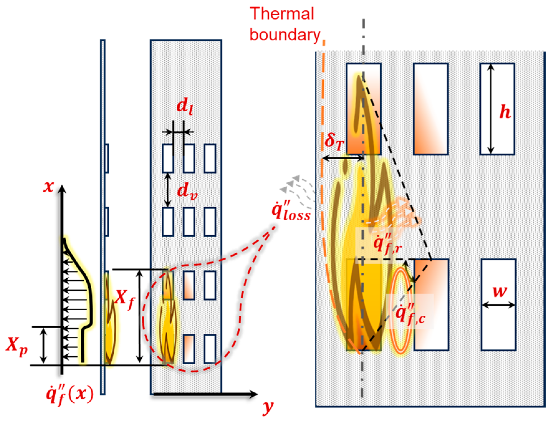
  • A critical thermal boundary layer thickness (~11.5 mm) governs the transition of heat transfer mechanisms: When the lateral spacing is below this threshold, both convective and radiative heat transfer jointly contribute to the ignition of adjacent fuels. As the spacing exceeds the boundary layer thickness, convection becomes negligible, and flame propagation relies primarily on radiation, resulting in delayed or inhibited lateral spread.
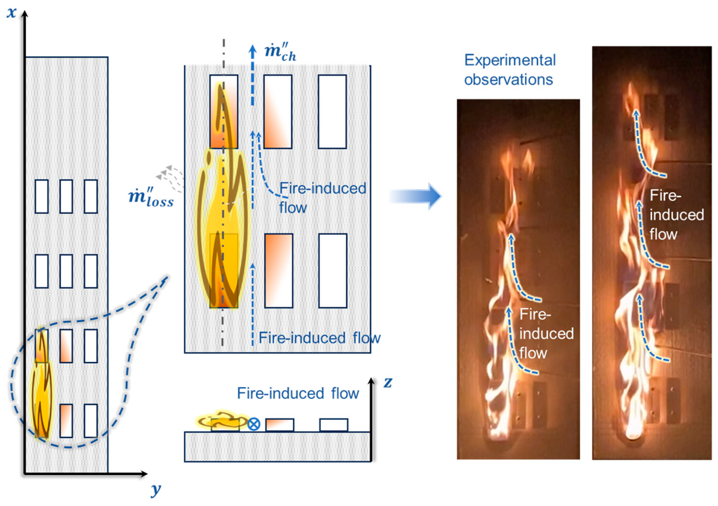
  • Chimney effect induced by lateral spacing significantly enhances mass transport and flame intensification: Moderate lateral spacing (e.g., 10 mm) generates optimal airflow entrainment pathways that intensify combustion by promoting increased oxygen supply and flame elongation. This effect explains the observed peak flame heights and elevated burning rates under such configurations.
These unique findings enhance our understanding of thermal–fluid interactions in discrete fuel arrangements and offer clear practical implications for fire safety engineering. Specifically, our results suggest that strategically increasing lateral spacing between combustible façade elements could substantially mitigate façade fire risk in modern high-rise buildings. Such insights can guide building designers and fire safety practitioners toward more effective preventive measures.
Future research will focus on validating and extending these findings through large-scale façade fire testing and detailed computational modeling under realistic environmental and material conditions. This will further confirm the applicability of our results and refine guidelines for practical fire safety design.

Author Contributions

Conceptualization, X.X. and Y.M.; methodology, X.X. and Y.M.; software, X.X.; validation, Y.M. and Y.W.; formal analysis, G.Z.; investigation, X.X.; resources, Z.H.; data curation, X.X.; writing—original draft preparation, X.X. and Y.M.; writing—review and editing, G.Z., Z.H. and Y.W.; visualization, X.X. and Y.M.; supervision, G.Z.; project administration, X.X.; funding acquisition, X.X. All authors have read and agreed to the published version of the manuscript.

Funding

This work was supported by the ‘Qinglan Project’ for Excellent Young Backbone Teachers of Jiangsu Higher Education Institution ([2024] No. 2).

Institutional Review Board Statement

Not applicable.

Informed Consent Statement

Not applicable.

Data Availability Statement

Data are available upon request from the authors.

Conflicts of Interest

The authors declare no conflicts of interest.

References

  1. Godakandage, R.; Weerasinghe, P.; Gamage, K.; Adnan, H.; Nguyen, K. A systematic review on cavity fires in buildings: Flame spread characteristics, fire risks, and safety measures. Fire 2023, 7, 12. [Google Scholar] [CrossRef]
  2. Torero, J.L. The building envelope: Failing to understand complexity in tall building design. In Rethinking Building Skins; Elsevier: Amsterdam, The Netherlands, 2022; pp. 341–357. [Google Scholar] [CrossRef]
  3. Chu, T.; Zhu, G.; Chai, G.; Gao, Y. Study on upward flame spread of cotton fabrics with different moisture regain. Case Stud. Therm. Eng. 2020, 21, 100683. [Google Scholar] [CrossRef]
  4. Finney, M.A.; Cohen, J.D.; Grenfell, I.C.; Yedinak, K.M. An examination of fire spread thresholds in discontinuous fuel beds. Int. J. Wildland Fire 2010, 19, 163–170. [Google Scholar] [CrossRef]
  5. Watanabe, Y.; Torikai, H.; Ito, A. Flame spread along a thin solid randomly distributed combustible and noncombustible areas. Proc. Combust. Inst. 2011, 33, 2449–2455. [Google Scholar] [CrossRef]
  6. V M, J.; Ambatipudi, M.K.; S, V. The phenomenon of flame jump in counter–current flame propagation in biomass packed beds—Experiments and theory. Combust. Sci. Technol. 2022, 194, 1199–1212. [Google Scholar] [CrossRef]
  7. Liu, Q.; Li, K.; Yuan, C.; Bian, N.; Li, Z.; Xu, W.; Chen, J. Numerical study on coupled combustion of PMMA counter-directional flame spread at variable slope. Fire 2025, 8, 219. [Google Scholar] [CrossRef]
  8. Bu, R.; Zhou, Y.; Shi, L.; Fan, C. Experimental study on combustion and flame spread characteristics in horizontal arrays of discrete fuels. Combust. Flame 2021, 225, 136–146. [Google Scholar] [CrossRef]
  9. Gollner, M.J.; Xie, Y.; Lee, M.; Nakamura, Y.; Rangwala, A.S. Burning behavior of vertical matchstick arrays. Combust. Sci. Technol. 2012, 184, 585–607. [Google Scholar] [CrossRef]
  10. Vogel, M.; Williams, F.A. Flame propagation along matchstick arrays. Combust. Sci. Technol. 1970, 1, 429–436. [Google Scholar] [CrossRef]
  11. Prahl, J.M.; Tien, J.S. Preliminary investigations of forced convection on flame propagation along paper and matchstick arrays. Combust. Sci. Technol. 1973, 7, 271–282. [Google Scholar] [CrossRef]
  12. Miller, C.H.; Gollner, M.J. Upward flame spread over discrete fuels. Fire Saf. J. 2015, 77, 36–45. [Google Scholar] [CrossRef]
  13. Xu, X.; Zhu, G.; Liu, X.; Zhang, X.; Chu, T. Experimental study on influence of air gap on upward flame spread over discrete fuel. Case Stud. Therm. Eng. 2021, 28, 101416. [Google Scholar] [CrossRef]
  14. Cui, W.; Liao, Y.-T.T. Experimental study of upward flame spread over discrete thin fuels. Fire Saf. J. 2019, 110, 102907. [Google Scholar] [CrossRef]
  15. Wolff, M.F.; Carrier, G.F.; Fendell, F.E. Wind-Aided Firespread Across Arrays of Discrete Fuel Elements. II. Experiment. Combust. Sci. Technol. 1991, 77, 261–289. [Google Scholar] [CrossRef]
  16. Luo, S.; Zhao, Y.; Zhang, H. Numerical study on opposed-flow flame spread over discrete fuels—The influence of gap size and opposed-flow velocity. Fuel 2021, 283, 118862. [Google Scholar] [CrossRef]
  17. Di Cristina, G.; Skowronski, N.S.; Simeoni, A.; Rangwala, A.S.; Im, S.-K. Flame spread behavior characterization of discrete fuel array under a forced flow. Proc. Combust. Inst. 2021, 38, 5109–5117. [Google Scholar] [CrossRef]
  18. Bu, R.; Shi, L.; Zhou, Y. Identifying the criterion for discrete flame spread over single-row birch rods. Fire Saf. J. 2021, 120, 103116. [Google Scholar] [CrossRef]
  19. Gollner, M.J.; Miller, C.H.; Tang, W.; Singh, A.V. The effect of flow and geometry on concurrent flame spread. Fire Saf. J. 2017, 91, 68–78. [Google Scholar] [CrossRef]
  20. Park, J.; Brucker, J.; Seballos, R.; Kwon, B.; Liao, Y.-T.T. Concurrent flame spread over discrete thin fuels. Combust. Flame 2018, 191, 116–125. [Google Scholar] [CrossRef]
  21. Čolić, A.; Pečur, I.B. Influence of horizontal and vertical barriers on fire development for ventilated façades. Fire Technol. 2020, 56, 1725–1754. [Google Scholar] [CrossRef]
  22. Di Cristina, G.; Skowronski, N.S.; Simeoni, A.; Rangwala, A.S.; Im, S.-K. Flame spread predictions over linear discrete fuel arrays using an empirical B-number model and stagnation point flow. Combust. Flame 2021, 234, 111644. [Google Scholar] [CrossRef]
  23. Zhang, X.; Chu, T.; Jiang, L.; Zhu, G.; Liu, X.; Xu, X.; Wu, Z. On the orientation effect on the flame spread over discrete fuel using a mass-transfer number. Fire Saf. J. 2023, 135, 103730. [Google Scholar] [CrossRef]
  24. Weber, R. A model for fire propagation in arrays. Math. Comput. Model. 1990, 13, 95–102. [Google Scholar] [CrossRef]
  25. Zhou, Y.; Bu, R.; Zhang, X.; Wang, Z.; Fan, C. Modelling of flame spread over biomass fuel arrays with various inclined angles and spacings. Fuel 2022, 335, 126744. [Google Scholar] [CrossRef]
  26. Jiang, L.; Zhao, Z.; Tang, W.; Miller, C.; Sun, J.-H.; Gollner, M.J. Flame spread and burning rates through vertical arrays of wooden dowels. Proc. Combust. Inst. 2019, 37, 3767–3774. [Google Scholar] [CrossRef]
  27. Apte, V.; Bilger, R.; Green, A.; Quintiere, J. Wind-aided turbulent flame spread and burning over large-scale horizontal PMMA surfaces. Combust. Flame 1991, 85, 169–184. [Google Scholar] [CrossRef]
  28. Chen, X.; Liu, J.; Zhou, Z.; Li, P.; Zhou, T.; Zhou, D.; Wang, J. Experimental and theoretical analysis on lateral flame spread over inclined PMMA surface. Int. J. Heat Mass Transf. 2015, 91, 68–76. [Google Scholar] [CrossRef]
  29. Ito, A.; Kashiwagi, T. Characterization of flame spread over PMMA using holographic interferometry sample orientation effects. Combust. Flame 1988, 71, 189–204. [Google Scholar] [CrossRef]
  30. Shaklein, A.A.; Bolkisev, A.A.; Karpov, A.I.; Korobeinichev, O.P.; Trubachev, S.A. Two-step gas-phase reaction model for the combustion of polymeric fuel. Fuel 2019, 255, 115878. [Google Scholar] [CrossRef]
  31. Jiang, L.; Miller, C.H.; Gollner, M.J.; Sun, J.-H. Sample width and thickness effects on horizontal flame spread over a thin PMMA surface. Proc. Combust. Inst. 2017, 36, 2987–2994. [Google Scholar] [CrossRef]
  32. Morrisset, D.; Santamaria, S.; Hadden, R.; Emberley, R. Implications of data smoothing on experimental mass loss rates. Fire Saf. J. 2022, 131, 103611. [Google Scholar] [CrossRef]
  33. The OpenCV Library. Available online: https://github.com/opencv/opencv/tree/4.12.0 (accessed on 3 March 2024).
  34. Chu, T.; Zhu, G.; Gao, Y.; Wang, P.; Chai, G.; Wang, Z. Combined effects of width and moisture content on upward flame spread over cotton fabrics. Case Stud. Therm. Eng. 2019, 15, 100514. [Google Scholar] [CrossRef]
  35. Pizzo, Y.; Consalvi, J.; Querre, P.; Coutin, M.; Audouin, L.; Porterie, B.; Torero, J. Experimental observations on the steady-state burning rate of a vertically oriented PMMA slab. Combust. Flame 2008, 152, 451–460. [Google Scholar] [CrossRef]
  36. Chung, B.T.F.; Naraghi, M.H.N. Some exact solutions for radiation view factors from spheres. AIAA J. 1981, 19, 1077–1081. [Google Scholar] [CrossRef]
  37. Pinto, P.; Severino, G.; Cruz, J.J.; Rivera, J.; Demarco, R.; Reszka, P.; Fuentes, A. Radiative characteristics of laminar Eucalyptus Globulus flames at different coflows. Int. J. Therm. Sci. 2024, 203, 109152. [Google Scholar] [CrossRef]
  38. Bergman, T.L.; Incropera, F.P. (Eds.) Fundamentals of Heat and Mass Transfer, 7th ed.; Wiley: Hoboken, NJ, USA, 2011. [Google Scholar]
  39. Pizzo, Y.; Consalvi, J.; Querre, P.; Coutin, M.; Porterie, B. Width effects on the early stage of upward flame spread over PMMA slabs: Experimental observations. Fire Saf. J. 2009, 44, 407–414. [Google Scholar] [CrossRef]
  40. Bradley, D.; Lawes, M.; Morsy, M. Flame speed and particle image velocimetry measurements of laminar burning velocities and Markstein numbers of some hydrocarbons. Fuel 2019, 243, 423–432. [Google Scholar] [CrossRef]
Figure 1. Objectives of the current research.
Fire 08 00284 g001
Figure 2. Experimental apparatus.
Fire 08 00284 g002
Figure 3. Evolutions of flame heights with time for each test scenario: (a) fuel matrix with a vertical spacing of 4 cm; (b) fuel matrix with a vertical spacing of 8 cm; (c) fuel matrix with a vertical spacing of 12 cm.
Fire 08 00284 g003
Figure 4. Evolution of the flame morphology of a fuel matrix with a lateral spacing of 5 mm.
Fire 08 00284 g004
Figure 5. Evolution of the flame morphology of a fuel matrix with a lateral spacing of 10 mm.
Fire 08 00284 g005
Figure 6. Evolution of the flame morphology of a fuel matrix with a lateral spacing of 15 mm.
Fire 08 00284 g006
Figure 7. Variations in (a) residual mass and (b) mass loss rate for different fuel matrix configurations.
Fire 08 00284 g007
Figure 8. Heat transfer process involved in the flame propagation over a fuel matrix.
Fire 08 00284 g008
Figure 9. Variation of view factors with lateral spacing for different reference ranges.
Fire 08 00284 g009
Figure 10. Development of thermal boundary layer thickness of initial flame.
Fire 08 00284 g010
Figure 11. Mass transfer process involved in the flame propagation over a fuel matrix.
Fire 08 00284 g011
Table 1. Test scenario settings for experimental investigation.
Test Scenario No.Lateral Spacing (mm)Vertical Spacing (cm)
154
258
3512
4104
5108
61012
7154
8158
91512
Table 2. Parameters for calculations of h c and δ T [23,28].
ParametersReference ValueUnit
P r 0.725
k g 0.0586W/m·K
g 9.81m/s2
v 8.989 × 10⁻⁵m/s2
α 1.262 × 10⁻⁴m/s2
β 0.003671/K
T f 1073K
T s 293K
Disclaimer/Publisher’s Note: The statements, opinions and data contained in all publications are solely those of the individual author(s) and contributor(s) and not of MDPI and/or the editor(s). MDPI and/or the editor(s) disclaim responsibility for any injury to people or property resulting from any ideas, methods, instructions or products referred to in the content.

