Abstract
Fire doors are installed between compartments to prevent the spread of fire. During a fire, the temperature difference between the exposed and unexposed surfaces induces bending deformation of the door, thereby reducing its fire resistance performance. Excessive deformation may further compromise the structural integrity of the door. This study presents a thermo-mechanical model that idealizes the bending behavior of double swing fire doors based on the deflection equation of a simply supported beam subjected to a thermal gradient between the tensile and compressive sides. A criterion of deformation, quantifying the relationship between the meeting stile gap and the resulting maximum deflection, is introduced and compared with the predicted values. The validity of the proposed model was confirmed through fire resistance tests conducted on both insulated and non-insulated fire door specimens, demonstrating strong agreement with experimental results. Furthermore, by comparing the predicted deformation with the deformation criterion, the impact of increasing gap sizes on the service life of fire doors on their fire resistance performance was evaluated. Based on this analysis, appropriate gap size limits for different door specifications are proposed to ensure reliable fire performance.
1. Introduction
Fire doors are a crucial element of passive fire protection systems, designed to mitigate fire spread, limit smoke penetration, and safeguard building occupants and property. By acting as physical barriers, fire doors prevent the transmission of heat, flames, and toxic gases between compartments. According to the ISO 834-1 [1] and ISO 3008-1 standards [2], fire doors must resist excessive deformation, prevent significant heat transfer, and minimize hot gas leakage under specified fire exposure durations.
The primary factor affecting fire door deformation is the temperature gradient between the heated and unheated surfaces. When exposed to fire, the heated side rapidly reaches high temperatures while the unheated side initially remains near room temperature. This thermal gradient induces thermal stress, leading to warping and deformation. Such deformation creates gaps between the door and the other door in the case of double swing doors, diminishing fire and smoke resistance performance, potentially causing fire doors to fail. Recognizing this issue, researchers have extensively studied their thermal and thermo-mechanical behavior in fire conditions.
Research methodologies generally include experimental testing and finite element modeling (FEM), emphasizing heat transfer, material behavior, and structural integrity. Hugi et al. [3] performed parametric FEM analyses of fire door frames, showing that frame insulation and material choice significantly influence fire protection performance. Capote et al. [4] investigated internal heat transfer in fire doors using temperature data and thermal imaging. The results showed that component separation at high temperatures increases internal convection and radiation, enhancing heat transfer. Boscariol et al. [5] studied the fire resistance performance of a single-leaf fire door used in marine applications by comparing an FEM analysis with actual test results, demonstrating the validity of the proposed model based on similar trends. Kyaw Oo D’Amore et al. [6] introduced optimized lightweight marine door designs to minimize heat transfer. Moro et al. [7] developed innovative door designs integrating optimized structural plates and insulation layers, proposing theoretical improvements to reduce thermally induced deformation. However, most studies have concentrated primarily on single-leaf fire doors.
For double-leaf fire doors, research remains limited. Tabaddor et al. [8] provided initial FEM insights, incorporating changes in material properties due to temperature variations. Although representing an early FEM-based analysis of fire resistance performance, their study lacked validation against actual test data. In contrast, Wu et al. [9] investigated steel fire doors without internal infill solely through experimental testing, demonstrating that their smoke resistance performance was superior to their insulation capability. Thanasoulas et al. [10] conducted fire resistance tests on typically used over-sized doors, approximately 3 m × 3 m and 5 m × 3 m (width × height), analyzing the impact of increased door width on fire performance. Khalifa et al. [11] performed both fire resistance tests and FEM analyses, comparing the results to experimental data, to propose optimal reinforcement cross-sections for minimizing deformation in double-leaf fire doors.
Studies on fire door gaps have also been conducted, but primarily focused on smoke leakage or heat loss through gaps. Cheung et al. [12] analyzed the influence of gaps on smoke resistance performance, conducting numerical analyses for various gap sizes and suggesting a 3 mm gap as optimal for both effective door operation and smoke resistance. Wakili et al. [13] provided valuable insights for fire door design by comparing experimental and numerical results related to the thermal insulation performance of door frames, particularly emphasizing the effectiveness of intumescent materials in gap situations. Kim et al. [14] presented research findings demonstrating improved airtightness and fire performance of fire doors incorporating vacuum insulation panels by applying graphite-based tapes to seal gaps. Despite substantial progress, maintaining consistent gap dimensions and long-term durability remain challenging [15]. Fire doors, commonly assembled through welding and manual methods, inherently struggle with gap precision and stability, leading to performance degradation over time.
The existing literature inadequately addresses the implications of increasing gaps, lacking a foundational theoretical framework, particularly in double-leaf fire doors. This research establishes a theoretical deformation model specifically tailored to double-leaf fire doors, attributing deformation primarily to thermal gradients between heated and unheated surfaces. Additionally, a simple geometric formula is presented to define criteria of deformation, with experimental validation provided through two comprehensive fire resistance tests. Furthermore, this study recommends appropriate gap tolerances to ensure sustained fire resistance, considering dimensional specifications and long-term durability.
2. Methods
Fire doors typically open and close as needed, serving as passageways for people or goods. However, they must remain closed during a fire to prevent the spread of flames. If the gap around a fire door is too small, it may not open and close smoothly under normal use. Conversely, if the gap is too large, the fire door can easily open even with slight impacts, making it difficult to maintain a properly closed state. The NFPA 80 Standard for Fire Doors and Other Opening Protectives Handbook [16] recommends a gap of 3.18 mm ± 1.59 mm to ensure fire doors perform effectively under both normal and fire conditions. Nevertheless, fire doors are generally manufactured by workers through welding at manufacturing facilities, and installation quality can significantly vary depending on the skills of on-site workers. These factors pose challenges in consistently meeting the required design gap specifications. Additionally, the research in [15] indicates that gaps in fire doors tend to increase gradually over the years of use, meaning the gap condition of each fire door may differ based on its specific usage after installation.
During fire resistance testing of fire doors according to ISO 3008-1 [2], the internal temperature of the heating furnace rises to 945 °C at the 60 min mark. The door leaf, composed of steel plates and core material, expands horizontally due to heating, while bending deformation simultaneously occurs because of the temperature difference between the heated and unheated surfaces. Excessive curvature, especially at the center of the leaf, can compromise the door’s latch or closure mechanism, causing unintended opening, which is the primary cause of failure in fire resistance tests of double-leaf fire doors. However, as illustrated in Figure 1, if the initial gap between the door leaves is small relative to the door width, the leaves quickly come into contact upon expansion, effectively supporting each other to withstand greater bending deformation. Conversely, a larger initial gap means the door leaves, even if initially touching upon expansion, will separate easily and open with minimal deformation. Therefore, as described in Equation (1), the expansion length of the door leaves and the gap between them are directly related to the maximum critical deformation that the door can withstand without opening.
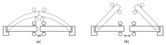
Figure 1.
Comparison of gap sizes: (a) Small gap; (b) large gap.
The fire door experiences bending deformation due to thermal expansion on the heated side and proportional compression on the unheated side. The deformation behavior can be represented using a second-order differential equation describing the proportional relationship between the tension side (heated surface) and compression side (unheated surface), as shown in Equation (2). Here, W is the total width of the double swing fire door, t is the thickness of the door, is the thermal expansion coefficient of steel, and and represent the temperatures on the heated and unheated surfaces, respectively (see Appendix A).
The deformation model for double-leaf fire doors presented in Equation (2) has the advantage of easily predicting deformation from fire door specifications. However, this simplified model does not account for the door’s length or for the reduction in the steel plate’s elastic modulus at elevated temperatures. In addition, it neglects the variable representing the gap between the two door leaves.
In the thermo-mechanical model (Section 2.1), the fire door is idealized as a simply supported beam subjected to a uniformly distributed load, , and the resulting deformation is combined with Equation (2) to establish a comprehensive deformation prediction model. Conversely, the geometric model (Section 2.2), as illustrated briefly in Figure 1, defines the maximum deformation a double-leaf fire door can withstand without opening, which is determined by the width of the door and the size of the gap between the leaves. Therefore, the geometric model provides the critical deformation criterion required for the double-leaf fire doors to maintain their fire resistance.
It is assumed that when the deformation predicted by the thermo-mechanical model exceeds the allowable deformation limit given by the criteria of deformation, the deformation of the fire door surpasses the acceptable threshold. To verify this assumption, fire resistance tests conducted on insulated and non-insulated fire doors are introduced in the fire resistance tests (Section 2.3).
2.1. Thermo-Mechanical Model: Prediction of Deformation
As shown in Figure 2, the deformation model driven by the temperature difference between the two surfaces and the model of the simply supported beam subjected to the uniformly distributed load exhibit the same form of bending deformation.
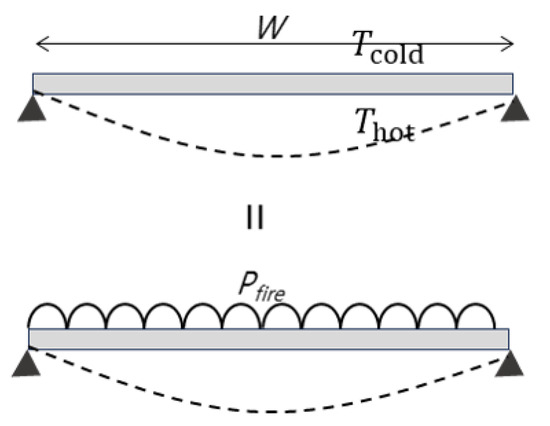
Figure 2.
Bending deformation compatibility.
The deflection formula for a simply supported beam subjected to a uniformly distributed load is given by Equation (3). Where I is the moment of inertia and E is the elastic modulus. When these two models are combined, the load , based on the fire door specifications and the temperature difference between the heated and unheated surfaces, can be derived as shown in Equation (4).
As shown in Figure 3, the deflection stiffness of a fire door is influenced by both its width (W) and height (L). The stiffness contribution from the width is formulated in Equation (5), while the contribution from the height—applicable to only one leaf—is given in Equation (6). Accordingly, the total deflection stiffness of a double-leaf door is expressed as the sum of both components, as shown in Equation (7), and the corresponding maximum deformation is derived in Equation (8).
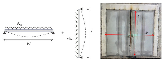
Figure 3.
Stiffness of a double swing fire door.
The surfaces of fire doors are composed of steel sheets that lose their elastic moduli at high temperatures. It is essential to consider the temperature-dependent modulus of elasticity to calculate the bending deformation caused by fire accurately. In this study, Poh’s modulus of elasticity reduction ratio [17], as specified in Equation (9), was used, and the applied temperature was assumed to be the temperature of the exposed surface.
2.2. Geometric Model: Criteria of Deformation
According to ISO 3008-1 [2], there should be no flame occurring on the unexposed side that lasts longer than 10 s, and the gap gauge specified in ISO 834-1 [1] must not pass through. In the case of single-leaf fire doors, the fire resistance can be assessed using only a thermo-deformation model of the door leaf, as there is no deformation of the door frame. However, double-leaf fire doors consist of two door leaves that deform together, making it impossible to evaluate fire resistance solely by establishing a thermo-deformation model. In this study, a method is presented to evaluate the fire resistance performance by comparing the deformation predicted by the thermo-deformation model with the critical deformation at which both door leaves disengage, resulting in the opening of the door and consequent loss of fire resistance.
Figure 4 shows the deformation shape of a double-leaf fire door during a fire resistance test. As discussed earlier, the double-leaf fire door with width (W) deforms like a single simply supported beam as both door leaves come into contact. The maximum deformation occurs until the door can no longer expand, causing the two leaves to separate from each other. The deformation at this moment is defined as the criteria of deformation.
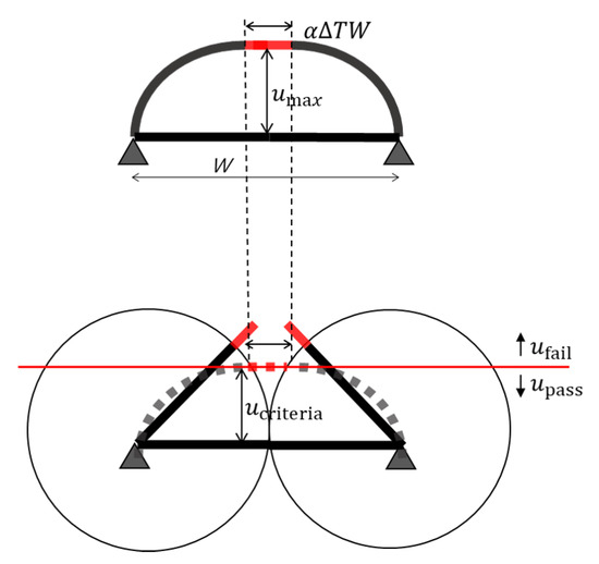
Figure 4.
Criteria of deformation.
Figure 5 illustrates the critical deformation of double-leaf fire doors, considering the gap between two door leaves. In the upper diagram, where no gap exists, the maximum critical deformation is expressed as , which can be calculated using the Pythagorean theorem, as shown in Equation (11). However, for double-leaf fire doors with an existing gap, part of the door’s expansion is already used in closing the gap, resulting in a deformation that is less than the maximum possible. Similar to Equation (11), the maximum critical deformation considering the gap can be expressed as shown in Equation (12).
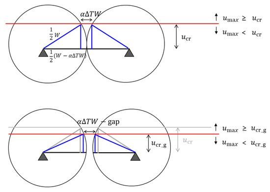
Figure 5.
Criteria of deformation depending on the gap size.
2.3. Fire Resistance Tests
A fire resistance test was conducted to verify the validity of the thermal deformation model for double swing fire doors expressed by Equation (10). The test specimens consisted of an insulated door and non-insulated door, representing typical products commercially available in the Korean market, as shown in Table 1. Both doors were pre-certified as E 60 (60 min integrity rating, non-insulating) under KS F 2268-1 prior to this study. The insulated door utilized mineral wool as its core material, while the non-insulated door had an internal core composed of paper honeycomb. Both specimens shared common specifications: gap size of , intentionally set and measured at the meeting-stile (lockset) position as a single test condition rather than an averaged value; and surface steel sheets made from galvanized steel, with a thermal expansion coefficient of .

Table 1.
Specifications of specimens.
Figure 6 shows the fire resistance test setup for the non-insulated specimen. The specimen was installed within a single frame, and the remaining opening was sealed using ALC blocks. After installation, the specimens were placed in a furnace for testing. They were exposed to fire following a standard heating curve. Temperatures on the fire-exposed side were measured using thermocouples specified in the fire test standard [1], while temperatures on the unexposed surface were measured using a thermal imaging camera. The fire resistance test was carried out for a total duration of 60 min, and deformation at the center of the specimens was measured at 5 min intervals using a laser distance meter.
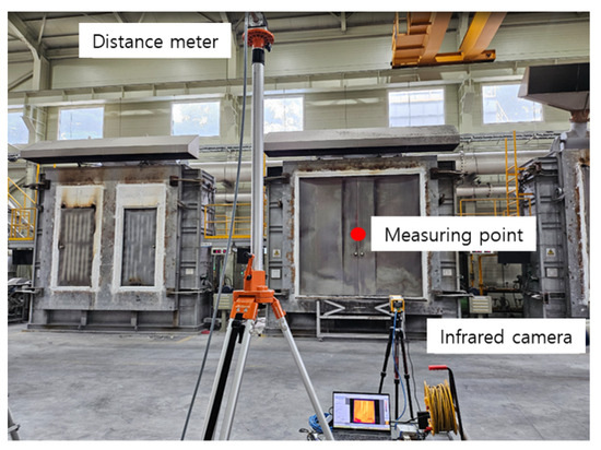
Figure 6.
Fire resistance test.
3. Results
3.1. Insulated Specimen
Figure 7 shows photographs of the unexposed surface of an insulated specimen at different time intervals. Since a fire door must prevent the spread of fire in the opposite direction regardless of where the fire originates, it must be tested in both directions. That is, during the fire resistance test, the door must remain closed and maintain its integrity regardless of the direction of the applied force. The upper image shows a fire door being pushed from the unexposed side, while the lower image shows a fire door being pulled from the exposed side. Regardless of the direction, the fire resistance test proceeds without any discoloration or deformation for the first 10 min after the test begins. Around 20 min, heat transfer occurs through the internal reinforcement. At about 30 min, the area where the two door leaves meet begins to show pronounced discoloration, indicating that heat transfer is taking place at that part. As time goes on, this trend intensifies, and between 50 and 60 min, a gap develops in the fire door on the pulled side, resulting in a loss of integrity.
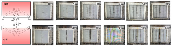
Figure 7.
Fire resistance test of insulated specimen.
Figure 8 shows the amount of deformation that occurred during the fire resistance test for the specimen with insulation. The deformation was measured at the center of the door leaf, as seen in Figure 6, using a laser distance meter at 5 min intervals. These measurement values are represented by blue dots. The black dashed line represents the predicted values obtained using the thermal deformation model for a double-sash fire door derived from Equation (10). When comparing the predicted and measured values using the Pearson correlation coefficient, which indicates the degree of correlation between the two variables, an excellent correlation of 0.97 was obtained. However, the measured and predicted values at 10 and 15 min show some differences, which are believed to be due to the vertical reinforcement applied to the test specimen. In the early stage of the fire resistance test, before the reinforcing bar became sufficiently hot, it maintained its modulus of elasticity and provided appropriate rigidity to the system; however, after 20 min, the overheated reinforcing bar appears to have lost its functionality. This trend is also evident in Figure 7, where discoloration of the vertical reinforcement is observed starting from 20 min. Since the prediction model does not reflect the presence of the reinforcing bar, it shows higher values than the measured ones during the early stage; however, after 20 min, it accurately predicts the deformation.
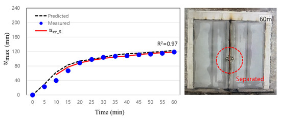
Figure 8.
Deformation of insulated specimen with the criteria line.
The red line represents the deformation criterion value derived from Equation (12) for a 5 mm gap. This curve indicates the maximum deformation the door can sustain without opening; any measured deformation that exceeds this criterion suggests the door may begin to open. From 25 min onward, the measured deformation surpasses the deformation criterion, and this trend persists until the test concludes. Although the deformation only slightly exceeds the threshold—insufficient to definitively open the door—the specimen, which had been barely holding its deformation at the threshold throughout the test, finally developed a large gap at 57 min and consequently lost its fire resistance.
3.2. Non-Insulated Specimen
Figure 9 displays time-sequential photographs of the non-exposed surface for the specimen without insulation. As with Figure 7, tests were conducted in both the pulling and pushing directions, and photographs of the non-exposed surface were taken at 10 min intervals. Unlike the specimen with insulation, the discoloration of the door leaf on the non-exposed surface was already complete by the 20 min mark. Although continuous deformation occurred thereafter, the door did not open, and the specimen maintained its fire resistance performance for 60 min. Figure 10 shows the temperature distribution on the non-exposed surface measured using a thermal imaging camera. It shows different distributions over time depending on the characteristics of the specimen.
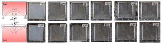
Figure 9.
Fire resistance test of non-insulated specimen.
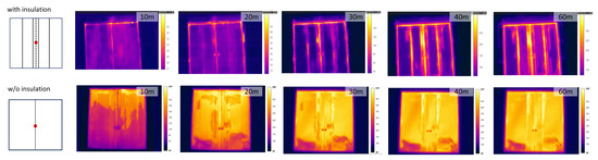
Figure 10.
Thermal image.
Figure 11 shows the deformation that occurred during the fire resistance test for the non-insulated specimen. The correlation coefficient between the predicted and measured values is 0.99, which is higher than that confirmed in Figure 8 for the specimen with insulation. The red line represents the deformation criterion corresponding to a 5 mm gap, and it can be observed that the measured values did not exceed this threshold during the 60 min fire resistance test. The test results also indicate that the specimen maintained its fire resistance performance for 60 min without any gap formation. Although the predicted values clearly exceed the deformation criterion, the actual measured values do not, from which it can be inferred that no gap formation occurred. The reason for the tendency of the predicted values to be slightly higher than the measured values during the latter part of the test (50–60 min) is that from 45 min onward, the surface temperature measured by the thermal imaging camera in that section increased sharply. This shows a trend different from the standard heating curve of the furnace from ISO 834-1 [1] and appears to be a limitation of the thermal imaging camera, which measures the surface temperature by receiving infrared radiation.

Figure 11.
Deformation of non-insulated specimen with the criteria line.
4. Discussion
A proper clearance is essential for a fire door to perform its opening and closing functions. However, an excessive clearance can be fatal during a fire because it facilitates the spread of toxic gases and flames, and it may even cause the fire door—which is required to withstand thermal deformation—to open. Moreover, fire doors are often welded by workers in small-scale factories, and the design clearance may vary depending on the skill of the installer at the site. In addition, the clearance can increase with use; one study found that an average clearance of 12.25 mm develops after just five years of use. Since such excessive clearance can affect the fire resistance performance of fire doors, the NFPA80 [16] restricts the clearance for hollow metal fire doors to 3.18 mm ± 1.59 mm.
In this section, the previously defined thermal deformation model and criteria deformation for double swing fire doors are utilized to compare the deformation values and standard criteria for fire doors with typical insulated and non-insulated specifications. Based on this comparison, the maximum gap sizes that can reliably ensure fire resistance are proposed for each size. Additionally, the appropriateness of the gap sizes specified in NFPA80 [16] is examined.
Figure 12 shows the predicted and measured values for the specimens with and without insulation examined earlier, and it presents the criteria for deformation for both a 12.5 mm and a 3 mm gap. This is based on the minimum gap of 3 mm specified in NFPA80 and the maximum gap of 12.5 mm observed in previous case studies [15]. Although the measured values should not exceed the performance criterion curve, both specimens show values that exceed it at a 12.5 mm gap. However, at a 3 mm gap, the measured values for both specimens remain below the threshold, suggesting that their fire resistance performance is not compromised. This finding contrasts with the 5 mm gap result observed in the specimen with insulation in Figure 8. In other words, for an insulated door with dimensions of 2400 2400 50, it can be proposed that a 3 mm gap is optimal for ensuring fire resistance performance. As for non-insulated doors, although the measured values indicate that a 5 mm gap might also be acceptable, the comparison using predicted values suggests that a 3 mm gap should be considered the appropriate clearance.
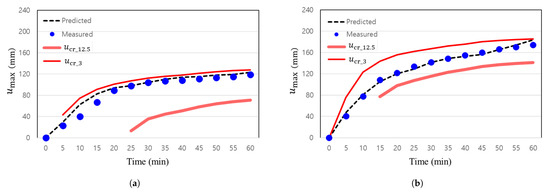
Figure 12.
Deformation of specimens with criteria lines: (a) Insulated specimen; (b) non-insulated specimen.
The deformation of the double swing fire door derived from Equation (10) was confirmed to have a high correlation with measurements obtained from actual tests. Based on the predicted values from the presented thermal deformation model, the “criteria of deformation” calculated in Equation (12) were compared, and Figure 13 shows the maximum gap for which the predicted values do not exceed the standard. In this study, appropriate gap sizes are proposed for fire doors with the specifications listed in Table 1, according to size. In addition, the gap sizes required by NFPA80 [16] are marked in red, with lighter shades indicating larger gaps. Moreover, cells corresponding to gaps stricter than those of NFPA80 [16] are filled in dark red. It can also be observed that, regardless of whether the door is insulated or non-insulated, the allowable gap size tends to increase as the width increases relative to the height.
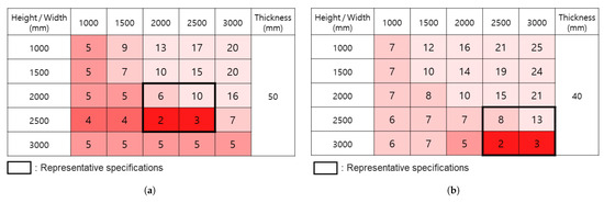
Figure 13.
Maximum clearance depending on specification of double swing fire doors: (a) Insulated; (b) Non-insulated. Note: Dark red = requires stricter gaps than NFPA80; Light red = NFPA80-compliant; Pale pink = exceeds NFPA80.
For insulated doors, the representative sizes fall between 2000 mm and 2500 mm, as indicated by the thick box lines. In most cases, applying the gap sizes specified by NFPA80 [16] does not cause significant issues. However, for the representative fire door sizes of 2000 mm × 2500 mm and 2500 mm × 2500 mm, the gaps that maintain fire resistance performance are suggested as 2 mm and 3 mm, respectively. For non-insulated doors, the representative sizes are those between 2500 mm and 3000 mm, also marked by the thick box lines. Similar to insulated doors, fire doors sized 2500 mm × 3000 mm and 3000 mm × 3000 mm should be managed with maximum gaps of 2 mm and 3 mm, respectively. This indicates that while the gap specifications required by NFPA80 [16] provide appropriate gap sizes, applying them uniformly across all sizes and performance standards may risk compromising the fire resistance capability.
5. Conclusions
In this study, the thermal deformation characteristics of double swing fire doors were expressed using a mathematical model, presenting a predictive model for bending deformation based on the temperature difference across the door leaves. Fire resistance tests conducted on both insulated and non-insulated doors confirmed a high Pearson correlation coefficient of 0.97–0.99 between the measured and predicted values, thereby validating the reliability of the model. Additionally, the maximum deformation related to the door’s expansion length was derived using a geometric approach and introduced as a performance indicator, enabling the predictive model to assess fire resistance performance rather than merely predicting deformation magnitude. Finally, gap sizes of 3–5 mm, as specified by NFPA80 [16], were examined, and it was found that for representative sizes of insulated and non-insulated fire doors, a stricter gap of 2–3 mm is required. Future work will extend the model and test program to glazed double swing fire doors, so that the influence of transparent infill panels on thermal deformation and gap-induced fire performance can be quantified.
Author Contributions
Conceptualization, B.L. and M.K.; methodology, B.L.; experiments, B.B. and M.J.; validation, B.L., C.L. and M.K.; formal analysis, B.L.; investigation, B.L.; resources, M.K.; data curation, B.L.; writing—original draft preparation, B.L.; writing—review and editing, H.L., C.L. and M.K.; visualization, B.L.; supervision, M.K.; funding acquisition, M.K. and C.Y. All authors have read and agreed to the published version of the manuscript.
Funding
This research was supported by the two funding sources including (1) the National Research Foundation of Korea (NRF) grant funded by the Korea Government (MSIP) (Grant No. RS-2024-00336025) and (2) the research grant of the Chungbuk National University in 2020.
Institutional Review Board Statement
Not applicable.
Informed Consent Statement
Not applicable.
Data Availability Statement
The experimental data supporting the results of this study are available upon request from the first author.
Conflicts of Interest
Authors Bohyuk Lim, Bongki Bae and Mingyu Jang were employed by the company AMI Inc. The remaining authors declare that the research was conducted in the absence of any commercial or financial relationships that could be construed as a potential conflict of interest.
Nomenclature
| Maximum deflection due to the temperature difference at center | |
| L | Distance between the lock and the top of the door |
| Coefficient of thermal expansion of a steel plate | |
| Temperature of the exposed surface (=) | |
| Temperature of the unexposed surface (=) | |
| t | Thickness of the door |
| Distributed load converted from the temperature difference between both surfaces | |
| Stiffness in height direction of steel plate based on the concentrated load () | |
| W | Width of the door |
| Average stiffness in the width direction | |
| Total stiffness of steel plate | |
| Elastic modulus at elevated temperature | |
| Elastic modulus of steel plate | |
| Temperature change at exposed side | |
| Criteria of deformation |
Appendix A
Figure A1 shows a simple beam that underwent bending deformation due to a temperature difference, along with an element of length dx. Assuming that is greater than , the side experiences a greater increase in length than the side. The resulting length difference is equal to the product of the angle dθ and the thickness t, as expressed in Equation (A2).
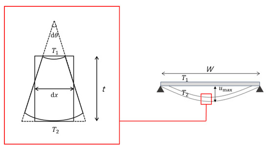
Figure A1.
Flexural deformation of a simple beam.
Through integration techniques using the two boundary conditions and , the maximum deflection due to the temperature difference on both sides was derived, as shown in Equation (A7).
Boundary condition 1:
Boundary condition 2:
References
- ISO 834-1:1999; Fire Resistance Tests—Elements of Building Construction. International Organization for Standardization: Geneve, Switzerland, 1999.
- ISO 3008-1:2019; Fire Resistance Tests, Door and Shutter Assemblies: General Requirements. International Organization for Standardization: Geneve, Switzerland, 2019.
- Hugi, E.; Wakili, K.G.; Wullschleger, L. Measured and calculated temperature evolution on the room side of a butted steel door frame subjected to the standard fire of ISO 834. Fire Saf. J. 2009, 44, 808–812. [Google Scholar] [CrossRef]
- Capote, J.; Alvear, D.; Abreu, O.; Lazaro, M.; Boffill, Y.; Manzanares, A.; Maamar, M. Assessment of physical phenomena associated to fire doors during standard tests. Fire Technol. 2013, 49, 357–378. [Google Scholar] [CrossRef]
- Boscariol, P.; De Bona, F.; Gasparetto, A.; Moro, L. Thermo-mechanical analysis of a fire door for naval applications. J. Fire Sci. 2015, 33, 142–156. [Google Scholar] [CrossRef]
- Kyaw Oo D’Amore, G.; Marinò, A.; Kašpar, J. Numerical modeling of fire resistance test as a tool to design lightweight marine fire doors: A preliminary study. J. Mar. Sci. Eng. 2020, 8, 520. [Google Scholar] [CrossRef]
- Moro, L.; Boscariol, P.; De Bona, F.; Gasparetto, A.; Srnec Novak, J. Innovative design of fire doors: Computational modeling and experimental validation. Fire Technol. 2017, 53, 1833–1846. [Google Scholar] [CrossRef]
- Tabaddor, M.; Gandhi, P.D.; Jones, G. Thermo-mechanical analysis of fire doors subjected to a fire endurance test. J. Fire Prot. Eng. 2009, 19, 51–71. [Google Scholar] [CrossRef]
- Wu, X.; Liu, J.y.; Zhao, X.; Yang, Z.; Xu, R. Study of the fire resistance performance of a kind of steel fire door. Procedia Eng. 2013, 52, 440–445. [Google Scholar] [CrossRef]
- Thanasoulas, I.; Lauridsen, D.; Husted, B.; Giuliani, L. Large-scale fire tests on sliding doors for building applications. Fire Technol. 2022, 58, 2357–2375. [Google Scholar] [CrossRef]
- Khalifa, M.A.; Aziz, M.A.; Hamza, M.; Abdo, S.; Gaheen, O.A. Improvement of fire door design using experimental and numerical modelling investigations. J. Struct. Fire Eng. 2021, 13, 205–223. [Google Scholar] [CrossRef]
- Cheung, S.C.; Lo, S.; Yeoh, G.; Yuen, R.K. The influence of gaps of fire-resisting doors on the smoke spread in a building fire. Fire Saf. J. 2006, 41, 539–546. [Google Scholar] [CrossRef]
- Wakili, K.G.; Wullschleger, L.; Hugi, E. Thermal behaviour of a steel door frame subjected to the standard fire of ISO 834: Measurements, numerical simulation and parameter study. Fire Saf. J. 2008, 43, 325–333. [Google Scholar] [CrossRef]
- Kim, Y.U.; Chang, S.J.; Lee, Y.J.; No, H.; Choi, G.S.; Kim, S. Evaluation of the applicability of high insulation fire door with vacuum insulation panels: Experimental results from fire resistance, airtightness, and condensation tests. J. Build. Eng. 2021, 43, 102800. [Google Scholar] [CrossRef]
- Kim, Y.S.; Huh, Y.R.; Jin, S.H.; Kwon, Y.J. Derivation of Defect Factors and Defect Rates of Fire Doors in Apartment Buildings through Field Investigation. Fire Sci. Eng. 2022, 36, 114–121. [Google Scholar] [CrossRef]
- American National Standards Institute. NFPA 80: Standard for Fire Doors and Other Opening Protectives Handbook; National Fire Protection Association: Quincy, MA, USA, 2016. [Google Scholar]
- Poh, K. Stress-strain-temperature relationship for structural steel. J. Mater. Civ. Eng. 2001, 13, 371–379. [Google Scholar] [CrossRef]
Disclaimer/Publisher’s Note: The statements, opinions and data contained in all publications are solely those of the individual author(s) and contributor(s) and not of MDPI and/or the editor(s). MDPI and/or the editor(s) disclaim responsibility for any injury to people or property resulting from any ideas, methods, instructions or products referred to in the content. |
© 2025 by the authors. Licensee MDPI, Basel, Switzerland. This article is an open access article distributed under the terms and conditions of the Creative Commons Attribution (CC BY) license (https://creativecommons.org/licenses/by/4.0/).