Article

Numerical Study on Coupled Combustion of PMMA Counter-Directional Flame Spread at Variable Slope

School of Resources & Safety Engineering, Central South University, Changsha 410083, China
*
Author to whom correspondence should be addressed.
Fire 2025, 8(6), 219; https://doi.org/10.3390/fire8060219
Submission received: 20 April 2025 / Revised: 20 May 2025 / Accepted: 26 May 2025 / Published: 29 May 2025

Abstract

This paper investigates the dual effects of slope variation and flame interaction on counter-directional flame propagation through numerical simulations of polymethylmethacrylate (PMMA) plates. Critical flame propagation parameters, including flame morphology, flame spread speed, mass loss rate, and radiative heat flux density, were analyzed using the Fire Dynamics Simulator (FDS v6.7.5) software. By comparing counter-directional flames and unilateral flames under varying slope conditions, we evaluated how flame interactions influence flame spread speed and mass loss rate, as well as the role of the view factor in radiative heat flux distribution. Numerical results revealed that the counter-directional fire propagation process on slopes could be divided into four distinct stages based on variations in flame spread rate and mass loss rate. Moreover, we propose a novel method to quantify flame interaction intensity on slopes using flame spread time. These findings enhance the mechanistic understanding of slope-dependent counter-directional flame propagation.

1. Introduction

In recent years, fire accidents of various types have occurred frequently, and flame spread over solid combustibles is widely recognized as the main cause of fire growth. Extensive studies have been conducted to investigate flame spread characteristics under external wind conditions, varying widths, and different slopes. Regarding slope effects, current research primarily focuses on three configurations: horizontal surfaces [1,2], vertical walls [3,4], and inclined surfaces [5,6,7]. Using FireFOAM, Zhang et al. [8] conducted qualitative and quantitative analyses of flow field distribution and flame attachment behavior on inclined solid surfaces, revealing abrupt changes in flame propagation speed and attachment length within a slope range of 10–20°. Huang et al. [9] investigated the combined effects of environmental wind and slope on heat transfer mechanisms and flame propagation characteristics, proposing a predictive formulation for flame spread rate that incorporates inclination angle and wind velocity. Their work analyzed the competition between buoyancy-driven acceleration induced by slope and wind-induced cooling.
While most studies focus on single fire sources, actual fire scenarios frequently involve multiple fire sources on solid combustibles. The interaction between fire sources can enhance fuel pyrolysis and combustion intensity, leading to significantly elevated fire spread rate. The coupled mechanisms between multiple fire sources, radiation heat feedback enhancement, and air entrainment restriction [10] could significantly increase fire intensity. Viegas et al. [11] developed an analytical model through theoretical and experimental investigations of interacting linear fire fronts, employing energy concentration concepts. Zhang et al. [12,13] conducted experiments using two gas flow meters to control the fuel supply rate and derived a dimensionless flame height equation and a flame height prediction model. Jiang et al. [14] conducted experimental studies using discrete wooden dowel arrays with varying spacing to explore flame propagation mechanisms between discrete fuel arrays. They developed a radiation-controlled model for horizontal flame spread that predicts horizontal flame spread rates for different dowel arrays. Joshi et al. [15] combined experimental and numerical simulations to investigate the downward flame propagation characteristics on multiple parallel fuel sheets with varying spacing.
Current multi-source fire research primarily focuses on analyzing the effects of fire source distribution patterns on flame morphology and interactions, while studies on multi-source fire spread processes remain relatively scarce. Furthermore, existing research predominantly investigates horizontal configurations, despite slope being a significant factor influencing fire spread behavior. The impact of slope variation on multi-source combustion and overall fire spread development trends has not been thoroughly investigated. Therefore, this paper aims to study the mechanisms of flame interaction during counter-directional flame spread on inclined surfaces. Specifically, by comparatively analyzing spread differences between unilateral and counter-directional flames under varying slopes and their behavioral contrasts under identical slope conditions, we qualitatively and quantitatively reveal intrinsic connections between slope angles and flame interaction intensity. The simulated experimental findings elucidate the fundamental mechanisms governing counter-directional flame propagation along inclined surfaces, particularly revealing how slope gradients modulate counter-directional flame propagation dynamics and their synergistic coupling effects in inclined configurations.

2. Materials and Methods

Polymethyl methacrylate (PMMA) exhibits exceptional optical clarity and superior chemical stability and has gained significant traction in architectural engineering applications, attributed to its good processability, pigment compatibility for customized aesthetics, and advantageous strength-to-weight ratio. Its controlled pyrolysis behavior, characterized by predictable heat release rates and minimal residue formation during combustion, renders it an archetypal surrogate for studying organic material responses in fire scenarios. This combination of structural functionality and controlled pyrolysis consistency establishes PMMA as a standard specimen for flame combustion studies.
The Fire Dynamics Simulator (FDS), an open-source computational fluid dynamics (CFD) platform developed by the National Institute of Standards and Technology (NIST), was employed to simulate fire-driven fluid transport, heat transfer, and mass exchange processes. Many scholars have verified the reliability of numerical models in FDS for solid surface fire spread. To investigate the effect of sample orientation on the auto-ignition and piloted ignition of PMMA, Peng et al. [16] compared and corroborated FDS numerical simulation results with experimental results. By using FDS, Rakesh Ranga et al. [17] carried numerical investigations of upward flame spread over flat PMMA slabs, obtained very plausible numerical predictions, and demonstrated the reliability of a simplified PMMA vaporization sublimation model for FDS applications. Furthermore, FDS demonstrates significantly reduced computational resource requirements compared to industry-standard CFD packages such as ANSYS Fluent and OpenFOAM. Based on the above, this study employs small-scale FDS simulations to investigate how slope influences counter-directional flame spread behavior on PMMA materials.

2.1. FDS Numerical Simulation

2.1.1. Pyrolysis Model

The Fire Dynamics Simulator (FDS) pyrolysis modeling framework categorizes material decomposition approaches into two distinct formulations: the simple pyrolysis model and the complex pyrolysis model. This study employs the sophisticated pyrolysis algorithm, which requires the specification of fuel thermophysical properties and pyrolysis parameters. To mitigate computational overhead associated with resolving multi-step reaction mechanisms, the solid materials are idealized as homogeneous monolithic substances within the computational domain. Consequently, the pyrolysis process is governed by the following reaction formalism:
  Solid 1 v g Char + v g Fuel
where vg represents the mass fraction of pyrolytic gas, and the reaction rate r of this first-order pyrolysis process is expressed as follows:
r = d Y s d t = A s Y s e E R T s
where Ys is the mass fraction of the material; As represents the pre-exponential factor of the solid-phase reaction, 1/s; and E denotes the activation energy of the reaction, kJ/kmol.

2.1.2. Turbulent Combustion Model

The FDS turbulent combustion model includes the Mixing-Controlled model and Finite-Rate model, with the former adopted in this study. The Mixing-Controlled model assumes that fuel and air react instantaneously upon mixing. In this framework, the combustion zone composition can be characterized by the mixing fraction. The mixing fraction refers to the proportion of a certain gas mass in a gas mixture composed of multiple components, and the mixing fraction is 1 for fuel on the surface of the fuel and 0 for air. The mixing fraction in the combustion region is a function of time and space, taking values in the range of 0–1.
The combustion process based on the mixing fraction is modeled as follows:
v f Fuel + v o O 2 i v p Products
where vf, vo, and vp are the stoichiometric coefficients of fuel, oxygen, and reaction products, respectively. Here, the subscript f denotes fuel, o denotes oxygen (O2), and p denotes reaction products.

2.1.3. Radiation Model

In the simulation, FireFOAM employs the finite volume Discrete Ordinates Model (fvDOM) to solve the Radiative Transfer Equation (RTE), where radiation intensity depends on spatial location and angular direction, discretized into 48 directions (3 × 4 azimuthal and 4 polar angles) [8,18,19]. The RTE is solved under the non-scattering gray gas model, with its simplified form:
s I ( x , s ) = κ ( x ) [ I b ( x ) I ( x , s ) ]
where I(x,s) is the radiative intensity at position x and direction s, W/(m2·sr). κ(x) is the absorption coefficient, m−1. Ib(x) is the blackbody radiative intensity, determined by the local temperature T(x):
I b ( x ) = σ T ( x ) 4 π
where σ is Stefan–Boltzmann constant, 5.67 × 10⁻⁸ W/(m2·K4).
The mean absorption coefficient κ is calculated using the narrow-band model:
κ I b = κ σ T 4 / π ,   inside   the   flame   zone max ( χ r q ˙ / 4 π , κ σ T 4 / π ) , outside   the   flame   zone
where χr is the radiative fraction and q ˙ is the volumetric heat release rate density (W/m3).
The net radiative heat flux density q ˙ r is expressed as the difference between the radiative energy density U(x) and the blackbody radiative energy density:
q ˙ r = q ˙ r ( x ) = κ ( x ) [ U ( x ) 4 π I b ( x ) ]
U ( x ) = 4 π I ( x ,   s )   d s

2.1.4. Material Parameter Setting

The polymethyl methacrylate (PMMA) specimens used in this study have a uniform thickness of 2.0 mm. The thermal penetration depth, which determines whether a solid fuel is thermally thin or thermally thick [20], is calculated as 2.2 mm for PMMA [21]. Hence, the 2 mm specimens used in this paper are thermally thin. For thermally thin materials, the temperature distribution is assumed to be uniform through the thickness direction. The properties of PMMA are listed in Table 1. For the substrate, the gypsum board material is available in PyroSim’s built-in database, thus requiring no additional parameter settings.
In FDS, the default configuration assumes multi-component solid-phase materials that may undergo multiple pyrolysis reactions. In this study focusing on PMMA, the solid is modeled as a single-component material using a one-step global Arrhenius reaction, where the polymer PMMA pyrolyzes into its monomer MMA. The solid-phase reaction follows a single-step global chemical equation [16]:
CH 2 C CH 3 COOCH 3 n n CH 2 C CH 3 COOCH 3
The reaction equation for the complete combustion of MMA (the main gaseous product of pyrolysis) with oxygen is modeled as follows, where the oxidation process in the solid phase is neglected [17]:
C 5 H 8 O 2 + 6 O 2 + 3 . 76 N 2 5 CO 2 + 4 H 2 O + 22 . 56 N 2

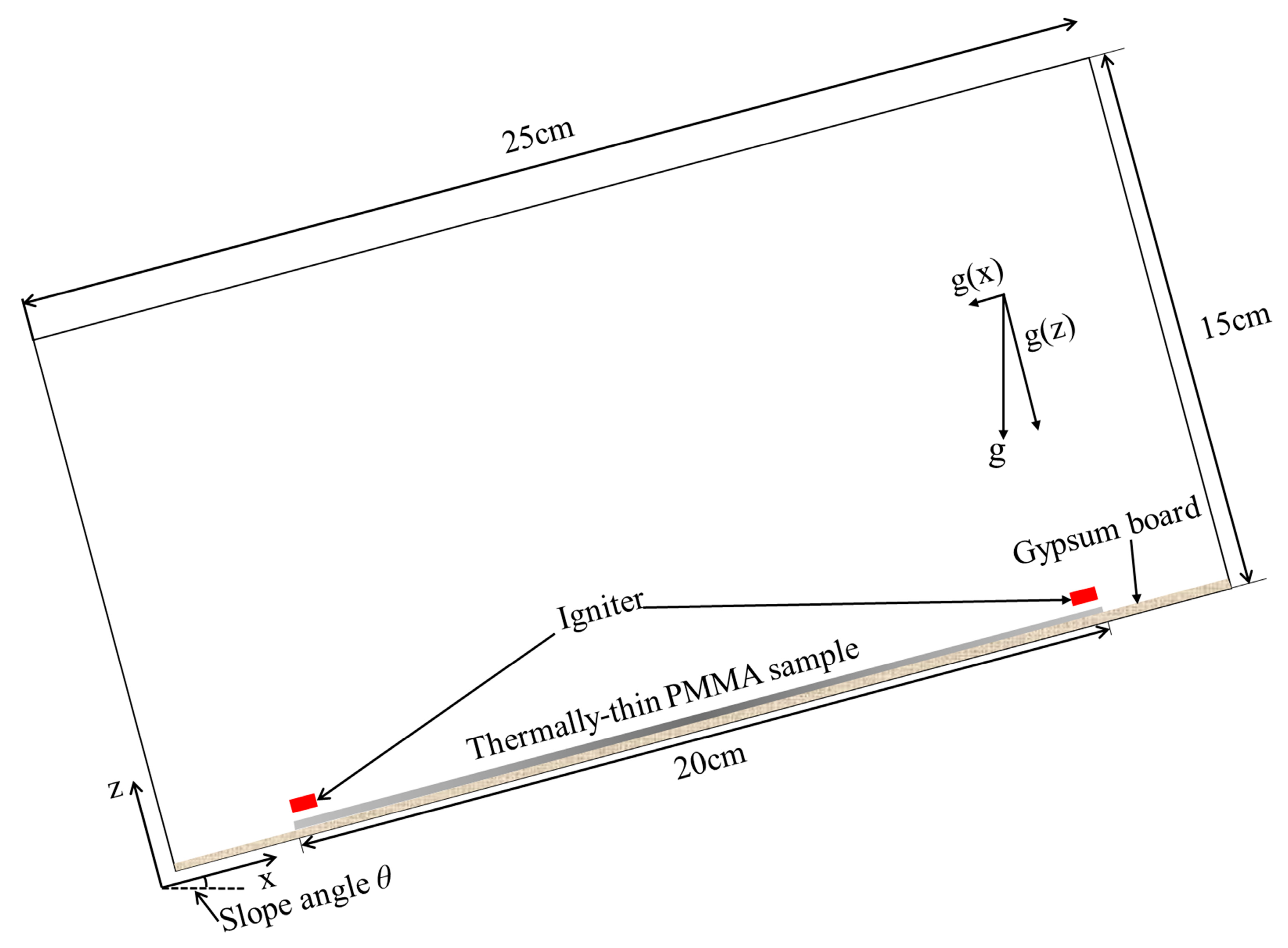
2.2. Simulation Configuration

The numerical simulation model for counter-directional flame spread was developed using FDS (version 6.7.5), as illustrated in Figure 1.
This study investigates counter-directional and unilateral flame spread over seven slope angles (0°, 10°, 15°, 20°, 25°, 30°, 35°). PMMA plates with uniform dimensions (Length (L) × Width (W) × Thickness (T): 200 mm × 30 mm × 2 mm) were used as the fuel. The gravitational acceleration vector was modified in the simulation to account for slope effects, with components adjusted based on the inclination angle:
g = 9.81   m / s 2
g x = g s i n θ
g z = g c o s θ
Table 2 shows the values of g(x) and g(z) under different slope conditions. When θ < 0°, the g(x) value aligns with the case of a positive slope with the same absolute angle, whereas the g(z) value is opposite.
A high-temperature ignition source (1200 °C) was employed to initiate combustion. To minimize thermal interference with flame spread process, the ignition source was automatically deactivated once sustained ignition was achieved, with its operational duration calibrated to 12–15 s through preliminary numerical simulations.
The initial air pressure in the gas-phase region was 101.325 kPa (standard atmospheric pressure); the ambient temperature was maintained at 20 °C, and the initial air consisted of 0.2101 volume fraction of oxygen and 0.7899 volume fraction of nitrogen. Given the thermally thin nature of the samples, the bottom boundary was treated as adiabatic. A non-combustible gypsum fireproof board was placed at the sample bottom, and the remaining five wall surfaces were defined as “OPEN” boundaries to ensure air circulation, complete combustion, and uninterrupted fire spread. The simulation duration was set at 1000–2000 s.

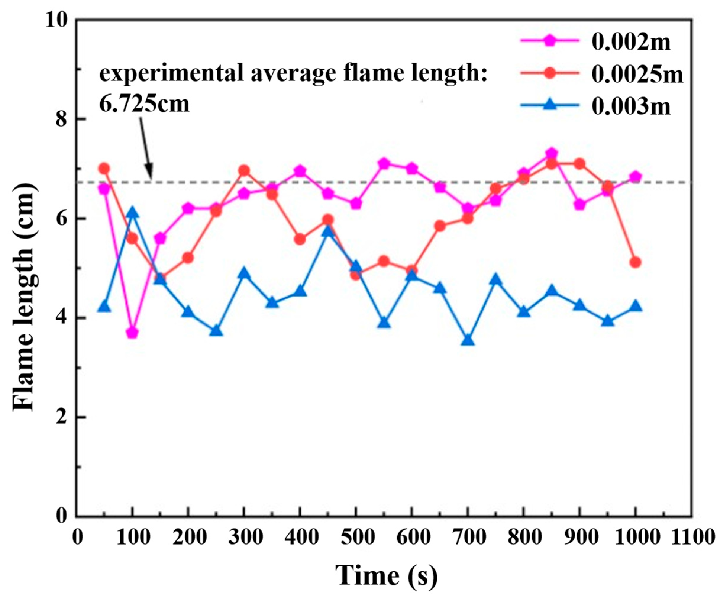
2.3. Meshing and Grid Independence Validation

In FDS simulations, the computational grid serves as the fundamental computational unit, where all numerical solutions are derived through grid-based computations. The grid resolution governs the spatiotemporal accuracy of partial differential equations within the computational domain. Finer grids increase computation time, while overly coarse grids reduce accuracy. These factors must be balanced to meet requirements, starting with coarse grids and gradually refining.
A grid sensitivity analysis was conducted with three resolutions (0.002 m, 0.0025 m, and 0.003 m). Given diverse fire scenarios, grid independence validation was performed using a benchmark horizontal flame spread configuration. The comparison of the numerical simulation results of flame length with the experimental results under the same PMMA plate scale conditions is shown in Figure 2.
Comparative analysis reveals that the 0.002 m mesh resolves longer flame lengths than the 0.003 m coarse mesh. The 0.0025 m medium-density mesh shows marginally shorter flames than the fine mesh, yet both finer meshes exhibit convergent behavior, while the coarse mesh displays significant deviation. Experimental validation [24] confirms that the fine mesh achieves minimal relative error (4.61%), outperforming the medium-density (10.86%) and coarse meshes (33%), which failed to accurately predict flame propagation.
Based on the grid sensitivity findings, 2 mm × 2 mm × 2 mm was selected as the numerical simulation mesh size to optimize computational expenditure while maintaining solution accuracy. The computational domain parameters and mesh specifications are detailed in Table 3.

2.4. Model Validation

The data processing and analysis in this study are based on reasonable parameter settings and assumptions obtained through the fire simulation software FDS v6.7.5. To validate the reliability of the model, further comparative observations between the simulation results and previous experimental data are required.

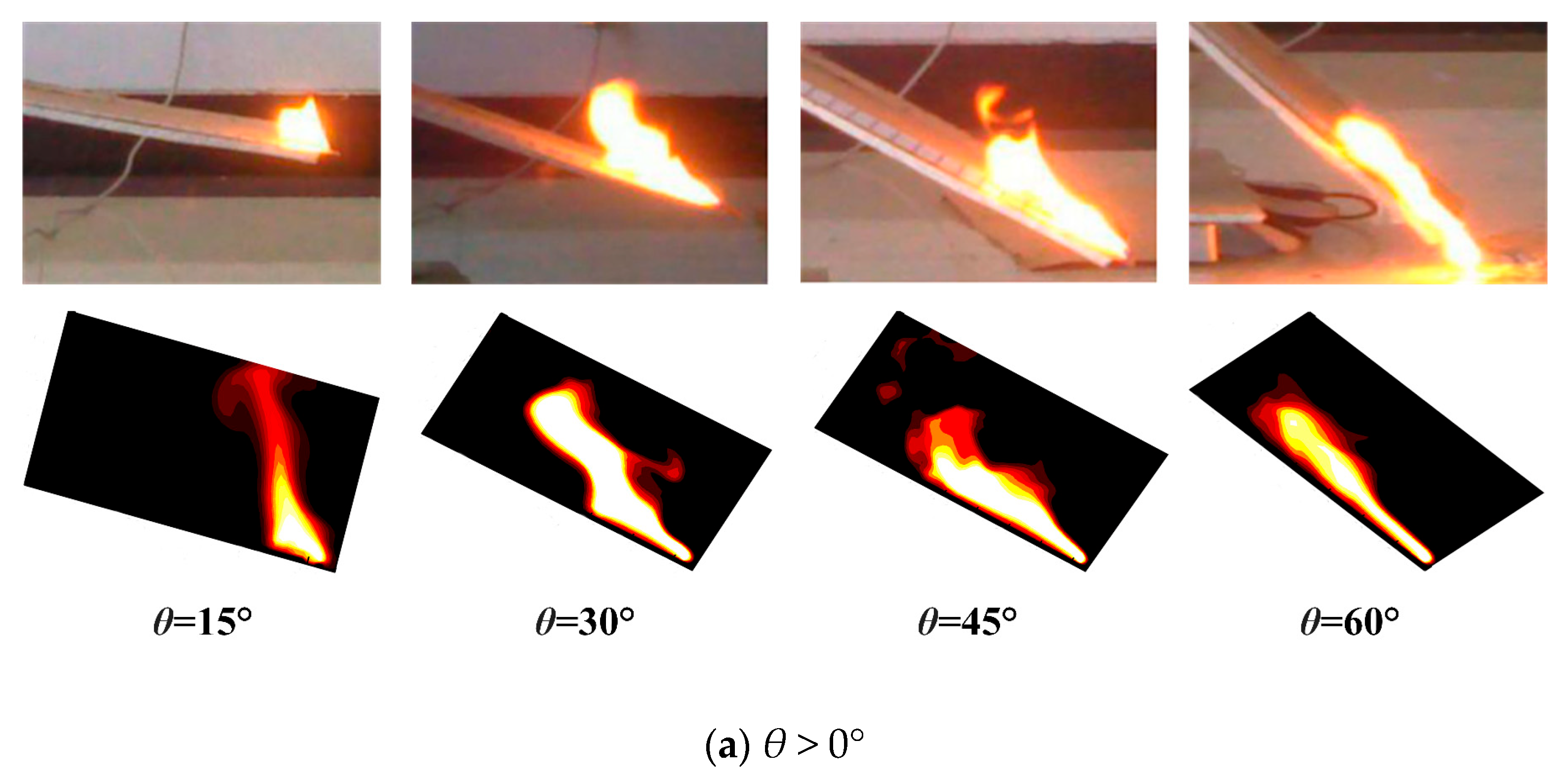
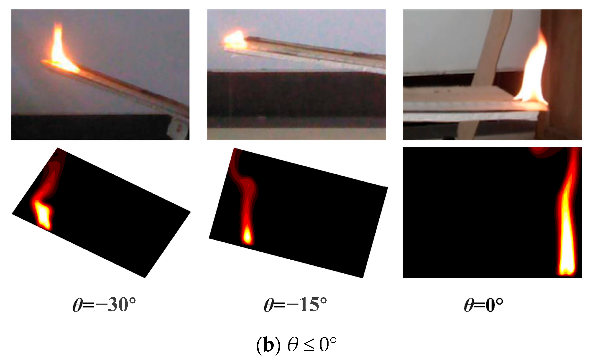
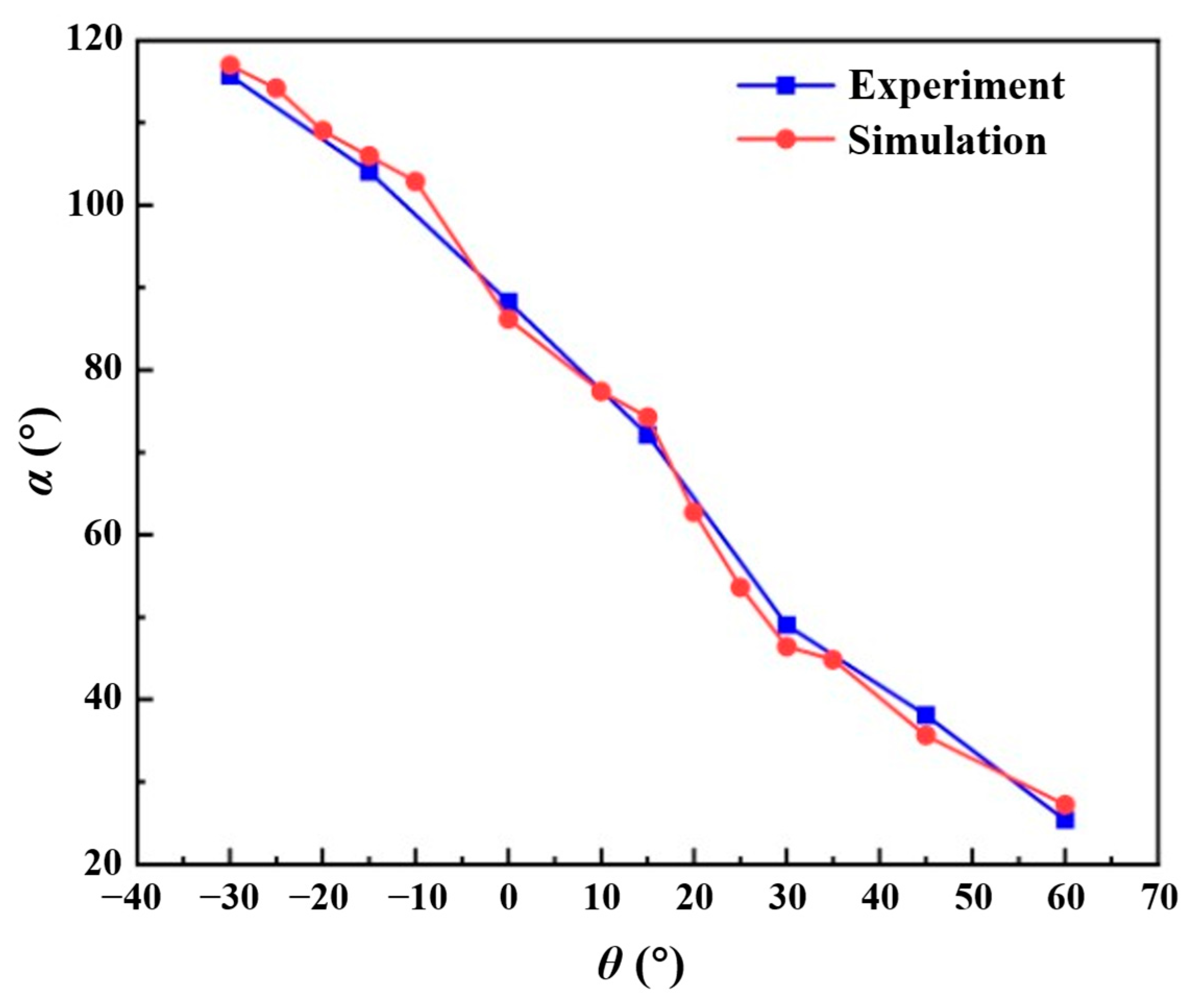
2.4.1. Validation Based on Flame Morphology

Figure 3 compares the flame morphology under slope conditions from FDS simulations with experimental results [24]. The FDS numerical simulations successfully reproduce the qualitative changes in flame structure observed in experiments. When θ ≤ 0°, the flame spread reaches a quasi-steady state, characterized by regular flame morphology with minimal fluctuations and predominantly laminar combustion reactions. For θ > 0°, under lower slope conditions, the flame remains detached from the solid surface. As the slope increases, the flame undergoes significant transformations: influenced by the Coanda effect, the flame gradually adheres to the combustible surface, becoming distinctly attached at a 60° slope. At a 45° slope, turbulent phenomena dominate the flame behavior, accompanied by the emergence of intermittent flame regions, indicative of fire plume dynamics.
Figure 4 compares the flame tilt angle α between experimental results [24] and numerical simulations for unilateral flame spread across varying slopes. The experiments utilized 2 mm thick thermally thin PMMA, consistent with the simulation setup. The results demonstrate good agreement between numerical and experimental data. During concurrent-flow flame spread, the flame tilt angle α progressively decreases as the slope increases, indicating closer proximity of the flame to the unburned fuel surface. Under negative slopes, the flame tilt angle α increases with decreasing slope magnitude, causing the flame to tilt toward the burned region of the fuel.

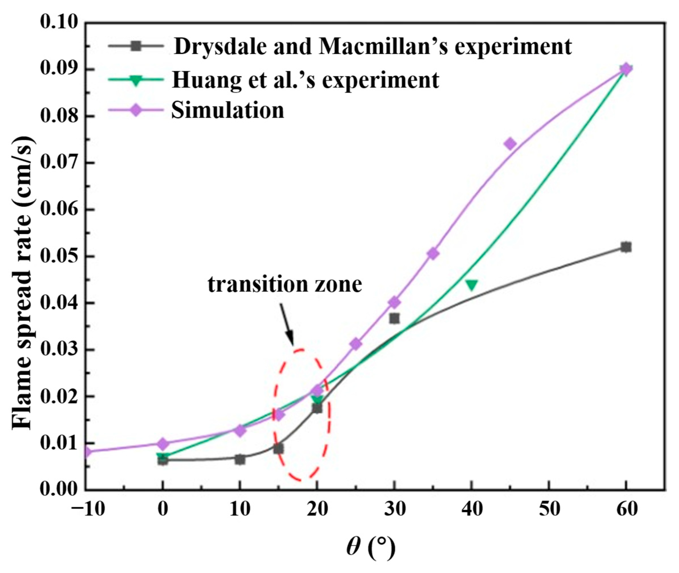
2.4.2. Validation Based on Flame Spread Rate

Variations in flame spread rate also serve as a critical indicator for validating the agreement between numerical simulations and experimental observations. Figure 5 compares the flame spread rates from numerical simulations with experimental data [6,9] under varying slopes. In these studies, Huang et al. [9] conducted experiments using 2 mm thick thermally thin PMMA sheets, while Drysdale and Macmillan [6] employed 6 mm thick PMMA sheets. The results reveal that the unilateral flame spread rate increases with slope angle, demonstrating good consistency with prior experimental findings. Notably, when the slope exceeds 20°, the flame spread rate exhibits a substantial increase, highlighting the pronounced influence of slope on flame propagation dynamics.
The findings [6] indicate the presence of a transition zone within the slope range of 15–20°, beyond which the flame spread rate increases sharply. Similarly, Zhang et al. [25] identified a critical transition region between 10° and 20° slopes. As shown in Figure 5, the simulation results also exhibit this phenomenon, confirming that the numerical simulation results align well with the experimental conclusions cited above.
Additionally, compared to experimental results, the flame spread rates obtained from FDS simulations are higher under certain slope conditions. This discrepancy may be attributed to differences in lateral boundary constraints: in the experiments conducted by Huang et al. [9], the sample edges were sealed with stainless steel frames to prevent lateral flame spread, whereas the edges of the PMMA sheet in the simulations were not similarly restricted, leading to an overestimation of the flame spread rate.

3. Results and Discussion

3.1. Flame Morphology

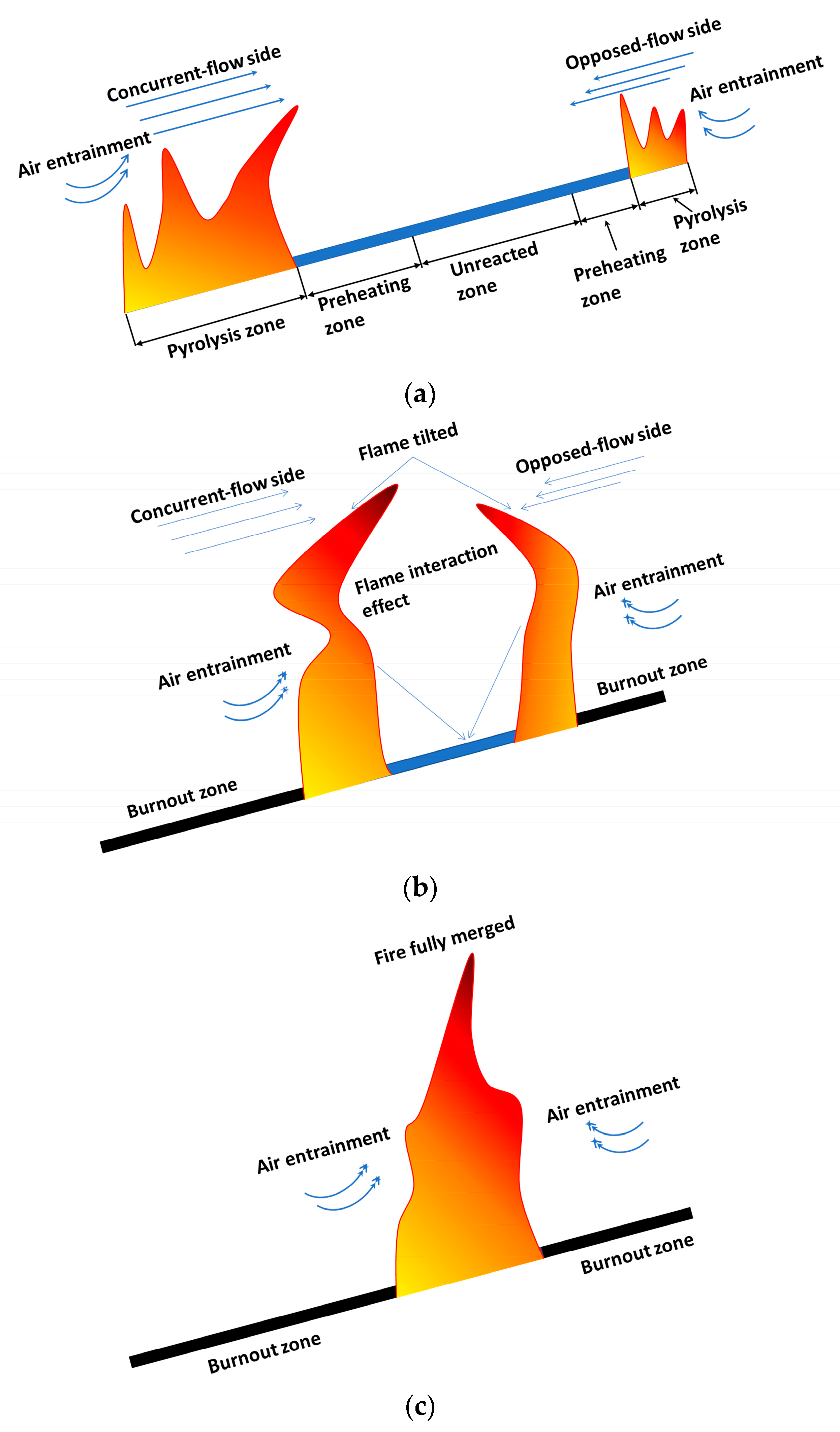
3.1.1. Flame Evolution Hypothesis

Flame morphology serves as an indicator of combustion intensity and exhibits intrinsic correlations with flame propagation characteristics, providing critical insights for fire spread investigations. According to our previous research [26] and the fire spread study summarized above, we assume that the typical variation of flame morphology on both sides of the counter-directional flame spread process under the effect of slope is shown in Figure 6. In contrast to conventional unidirectional flame spread, counter-directional propagation exhibits enhanced behavioral complexity due to flame interactions. During the early phase of counter-directional flame propagation, combustion-induced interactions exert negligible influence on morphological characteristics. Progressive flame advancement induces mutual proximity of dual pyrolysis fronts within the combustion zone, where modifications in heat flux distribution and combustion rate variations are observed to correlate with interaction dynamics. Pronounced aerodynamic pressure gradients emerge, inducing streamwise flame elongation (particularly evident along adjacent flame boundaries) and mutual inclination until the flames appear to be fully fused.

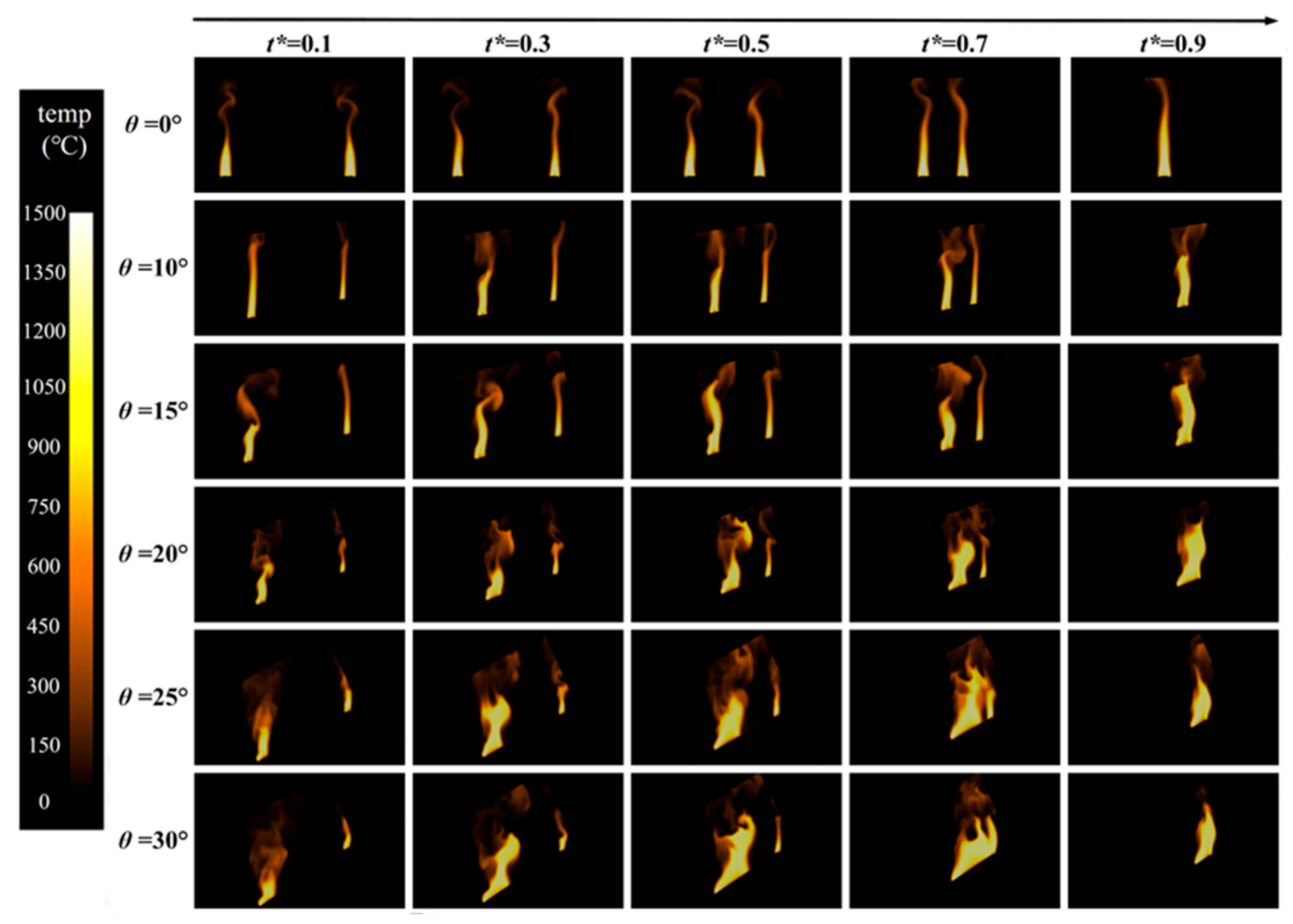
3.1.2. Flame Morphology Analysis

The simulation-derived datasets were processed through Tecplot 360 for spatiotemporal visualization, enabling systematic capture of flame morphological evolution across discrete time intervals under six slope configurations. Given that fire spread rates and morphological characteristics exhibit significant slope dependence, to enable cross-slope comparison of flame development stages, a dimensionless temporal coordinate t* was formulated:
t * = t T
where t is the instantaneous fire spread time, s; and T is the total fire spread time under the corresponding working conditions, s.
Figure 7 shows the flame morphology evolution during unilateral flame spread under varying slopes. At 0° and 10° slopes, the flame morphology remains relatively stable, gradually reaching a quasi-steady state with minimal variation. When the slope increases beyond 20°, the flame exhibits significant morphological fluctuations and turbulence, with rapid flame area expansion and accelerated spread rate. Comparative analysis of concurrent flame morphologies at identical dimensionless times reveals that as slope increases, the flame plume progressively attaches to the inclined surface, with the angle between the flame and solid surface correspondingly decreasing.
In contrast to concurrent-flow spread, opposed-flow flame spread demonstrates morphological oscillations post-ignition before stabilizing. During the stable phase, reduced slopes yield smaller flame areas, with flames increasingly leaning toward the burnout zone of the solid surface as slopes decrease.
Figure 8 illustrates the temporal evolution of counter-directional flame morphology under varying slope conditions. Under horizontal conditions (θ = 0°), the counter-directional flame spread exhibits symmetric morphological evolution. At the initial stage (t* = 0.1), simultaneous ignition at both ends produces spatially separated flame fronts with limited extension and negligible interaction due to large inter-flame distances. Progressive flame advancement leads to gradual convergence of dual combustion zones, during which mutual interactions become increasingly prominent. With the further approach of the flames on both sides, the flames gradually fuse and the maximum flame height appears after complete fusion. The terminal phase (t* = 0.9) corresponds to residual fuel depletion and flame extinction, transitioning to a single decaying combustion source.
For slopes exceeding, flame morphology demonstrates differences from horizontal configurations (θ = 0°), characterized by slope-induced asymmetric fire propagation. The slope effect differentiates the fire spread into two distinct regimes: the concurrent-flow side and the opposed-flow side. The concurrent-flow regime demonstrates closer proximity to the preheating interface, exhibiting expanded preheating regions and accelerated propagation velocities compared to the opposed-flow counterpart. The observed morphological evolution during counter-directional flame propagation experimentally validates the combustion hypothesis proposed in Figure 6.

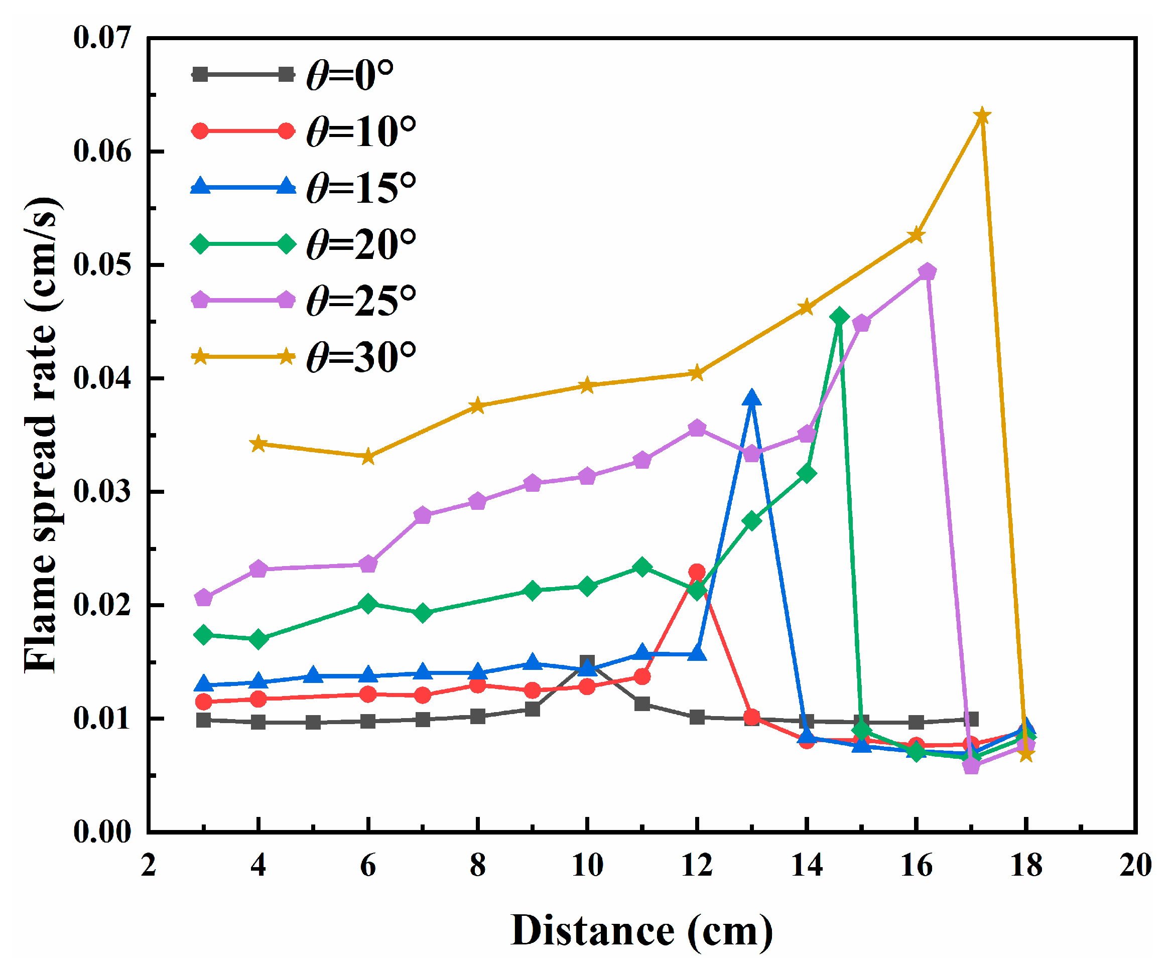
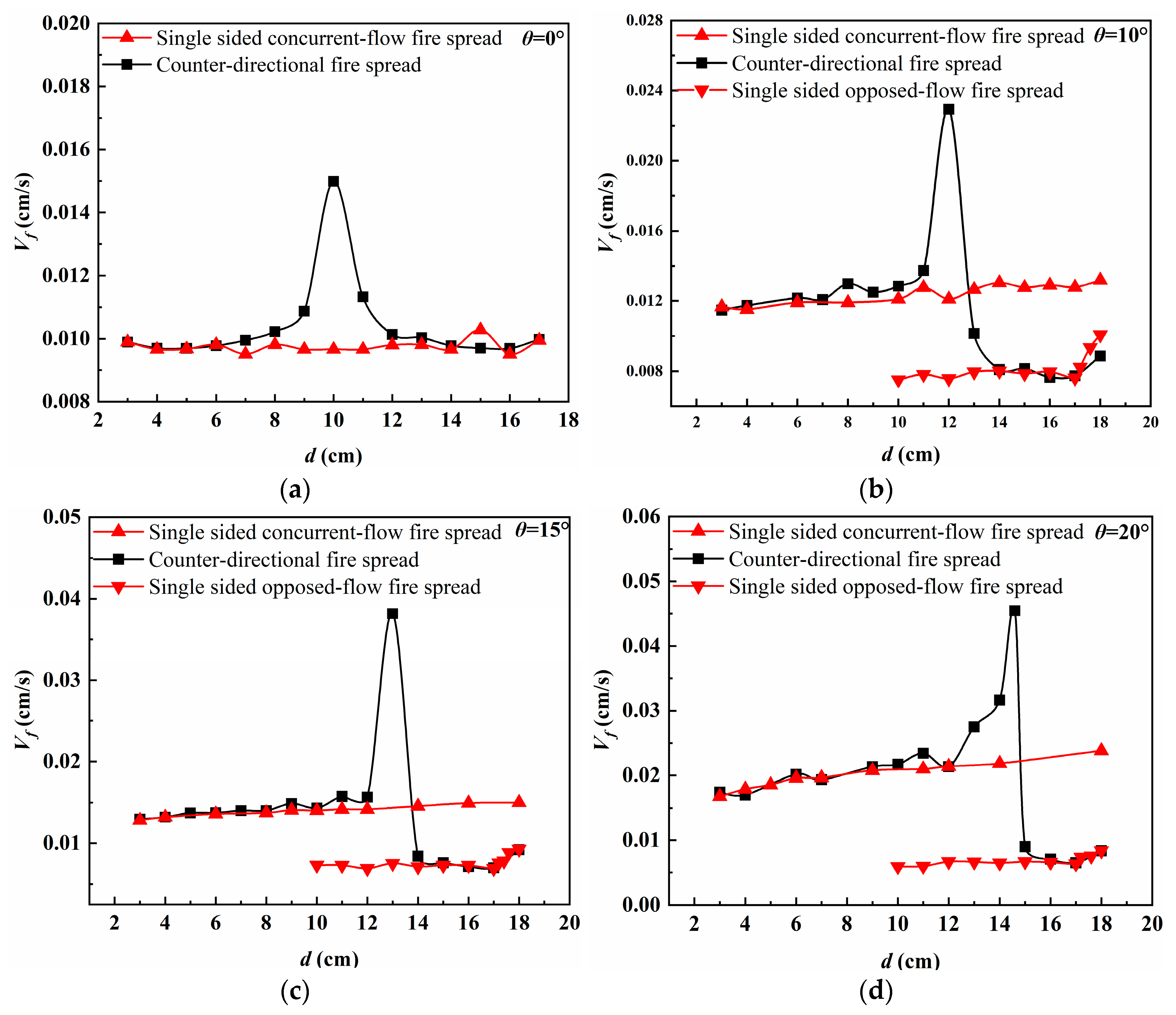
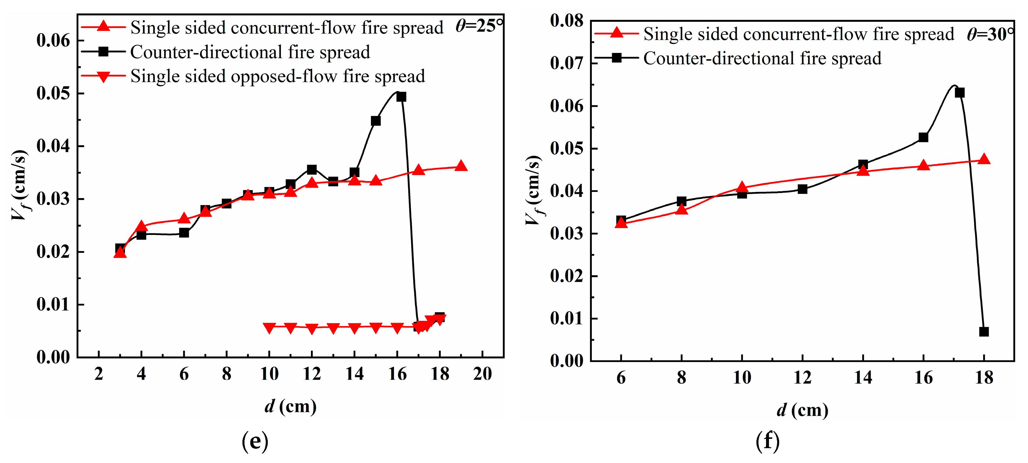
3.2. Flame Spread Rate
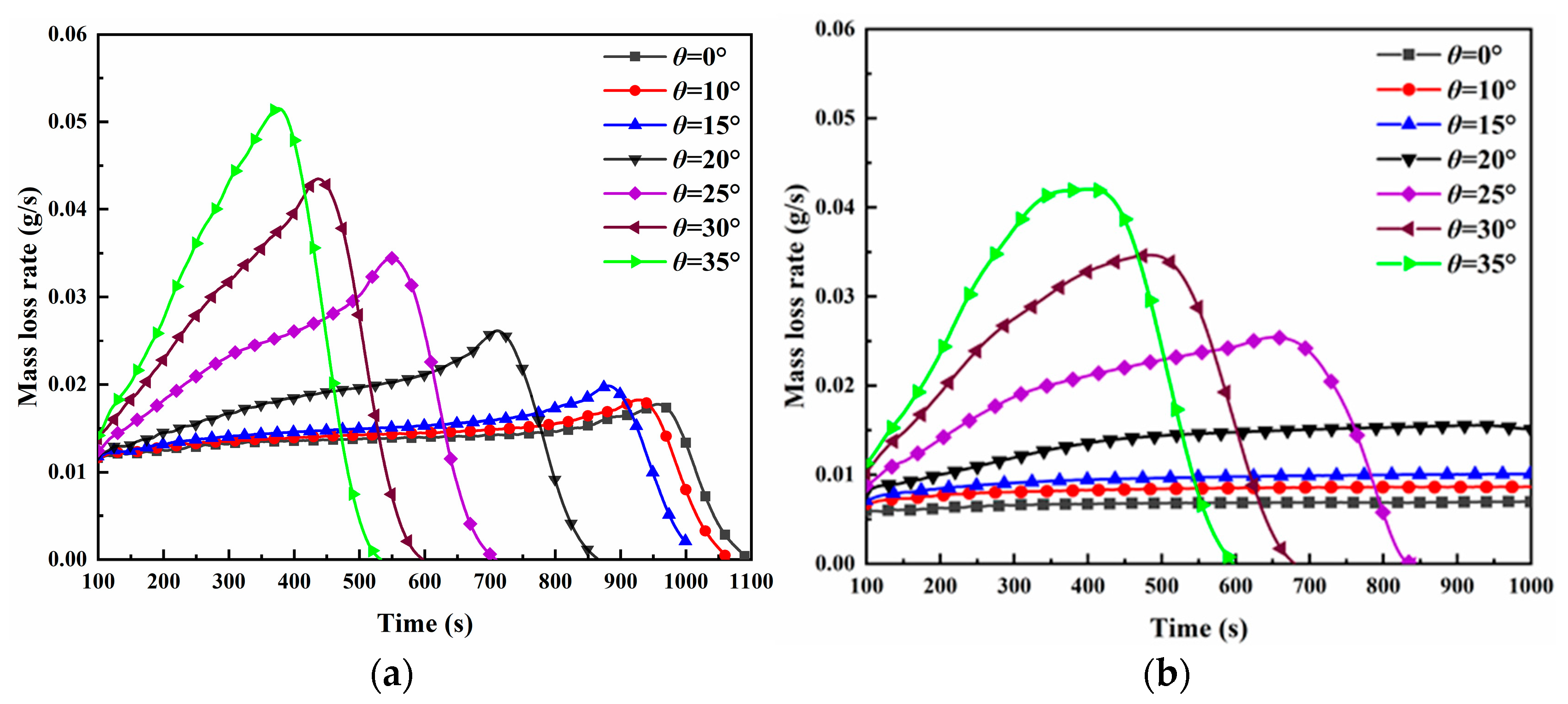
The flame spread rate was quantified by tracking the travel distance of the pyrolysis front per unit time. The method builds on established thermal standards for PMMA combustion: Xie and Desjardin [27] defined 379.85 °C as the reference temperature for PMMA fire spread to locate the pyrolysis front, whereas Ito and Kashiwagi [20] suggested that the solid surface temperature of PMMA before evaporation was about 380 °C during downward flame spread. Synthesizing these findings, the present study defines thermal domains, with 100~380 °C demarcating the preheat zone and temperatures exceeding 380 °C characterizing the pyrolysis zone. The temperature variation of PMMA surface was obtained through thermocouples placed at equal distances (2 cm apart) on the material’s surface and temperature profile across the solid-phase surface. The instance when the combustible material’s surface temperature first reached 380 °C was identified, enabling determination of the pyrolysis front location.
The flame spread rate Vf can be calculated as follows:
V f = d s d t = s ( t + Δ t ) s ( t ) Δ t
where ds is the differential displacement of the pyrolysis front, dt is the differential of the fire spread time, and Δt is the change in spread time, defined by the time it takes the next monitored point to reach 380 °C, s. With the change of slope, the flame contact and fusion position of the two sides of the counter-directional flame spread also changed. The contact time of the flame fronts under different slopes, along with the spread distances on both the opposed-flow and concurrent-flow sides during flame contact, is provided in Table 4. Under the slope angles tested here with a constant PMMA plate length, the counter-directional flame spread system demonstrates a positive correlation between increasing slope angles and propagation velocity within the integrated combustion framework.
Ending with the contact and merging of both flame fronts, the flame spread rates on each side during counter-directional flame spread were calculated separately. Figure 9 shows instantaneous fire spread rate changes at each position under varying slopes. The origin point on the concurrent-flow side served as the reference for distance (d) measurements, while the opposed-flow side’s starting point was d = 20 cm. The visualization demonstrates dynamic flame spread speed along both PMMA plate surfaces, with the maximum rate occurring when the pyrolysis fronts interacted. This peak rate value was derived through time-resolved tracking of concurrent-flow side pyrolysis front displacement.
Combustion interactions significantly accelerate counter-directional flame spread under varying slopes. Peak fire spread rates increase with slope angle, showing more pronounced rises during 10–15° and 25–30° transitions. Concurrent-flow spread distance at pyrolysis front interaction increased with slope, while opposed-flow distance decreased. Under identical slopes, both sides of the pyrolytic front contact shared same fire spread time: concurrent-flow speed increased significantly with slope, opposed-flow rate decreased, and their difference increased gradually. Moreover, slope increases exerted stronger acceleration effects on concurrent-flow spread than deceleration impacts on opposed-flow.
The analysis demonstrates that increasing slope angles progressively favor concurrent-flow flame propagation over opposed-flow spread. For this reason, during counter-directional flame propagation, the spread distance of the concurrent-flow flame consistently exceeds that of the opposed-flow flame, with its contribution to the overall propagation process being significantly greater. Given this asymmetric behavior, in the remaining chapters of this paper, when comparing single-sided flame combustion with counter-directional flame combustion, the concurrent-flow flame is selected as the representative unilateral case for comparative analysis against counter-directional flame spread. Figure 10 compares flame spread velocities between unilateral (concurrent-flow only) and counter-directional propagation modes across different slope angles.
During the initial phase preceding flame coupling, the concurrent-flow flame in counter-directional propagation maintains velocity characteristics matching unilateral flame spread, with minimal rate variation under quasi-steady state conditions. Slope effects equally affect unilateral flames and the concurrent-flow component of counter-directional flames. As opposed-flow flame fronts approach, their thermal interaction increasingly accelerates flame spread. This enhancement becomes most noticeable as flames near contact. The combined effect of slope orientation and flame interaction produces markedly faster spread rates than single-direction flame propagation under identical slope conditions.
During counter-directional flame spread, localized deceleration occurs due to oxygen competition between the approaching flame fronts. This transient speed reduction stems from an air entrainment restriction mechanism, where the converging flames mutually constrain fresh airflow, temporarily reducing combustion efficiency. However, this deceleration phase is spatially limited and temporally transient, exerting negligible influence on the overall counter-directional flame spread dynamics.

3.3. Mass Loss Rate

The radiative heat feedback enhancement effect present in the combustion process of counter-directional flame directly affects the burning intensity. Since the burning rate is an important characteristic parameter reflecting the burning intensity [28], this section discusses the variation of the burning rate in counter-directional flame spread at different slopes. Simulated mass loss data for both unilateral and counter-directional cases were processed using Savitzky–Golay filtering (5th-order polynomial smoothing) to eliminate high-frequency noise while preserving essential combustion trends. The resultant smoothed mass loss rate profiles are comparatively presented in Figure 11.
Figure 11a illustrates slope-dependent variations in mass loss rate during counter-directional flame propagation. For slopes between 0° and 15°, the mass loss rate maintains prolonged stability with minimal fluctuations until the approaching flames enter their interaction zone, where coupled combustion effects induce rapid acceleration that peaks upon complete pyrolysis zone merger. Following flame fusion, the unified fire source shows gradually declining mass loss rates until burnout. This stable phase diminishes at 20° and 25° slopes due to enhanced concurrent-flow propagation, though flame interaction still induces distinct mass loss rate surges. At these moderate slopes, the interaction effect remains significant despite the diminished stability period. The behavior changes markedly at a 35° slope, where the mass loss rate exhibits continuous growth toward peak values without displaying clear flame interaction characteristics, suggesting that slope effects dominate the combustion dynamics at steep inclinations.
For unilateral flame spread as shown in Figure 11b, at 0–15° slopes, the temporal mass loss rate remains low with flat curve morphology; the pyrolysis zone shows minimal variation during stable flame propagation, indicating steady-state combustion characteristics. Under this slope condition, no significant peaks appeared during unilateral flame combustion compared to counter-directional flame combustion. When the slope exceeds 20°, however, the relationship between mass loss rate and time no longer remains stable and a significant acceleration can be observed. Concurrently, the mass loss rate shows a certain dependence on the slope, with an increase in the mass loss rate as the slope increases. Under this slope condition, unilateral and counter-directional flame combustion exhibit similar mass loss rate curves: both show peaks but lack the abrupt increase induced by coupled counter-current combustion.
As summarized in Figure 12, comparative analysis of flame spread characteristics in Figure 10 and Figure 11 allows clear identification of distinct propagation stages.
Counter-directional flame spread under slope effects can be divided into four stages: ignition, independent combustion, flame interaction, and fuel burnout. At lower slope angles (0–15°), the independent combustion stage exhibits relatively stable flame spread behavior. When slopes reach 20° or greater, the concurrent-flow side in counter-directional flame spread is significantly enhanced by slope effects. Furthermore, the coupling mechanism between slope and flame interaction accelerates fire propagation during the flame interaction stage.

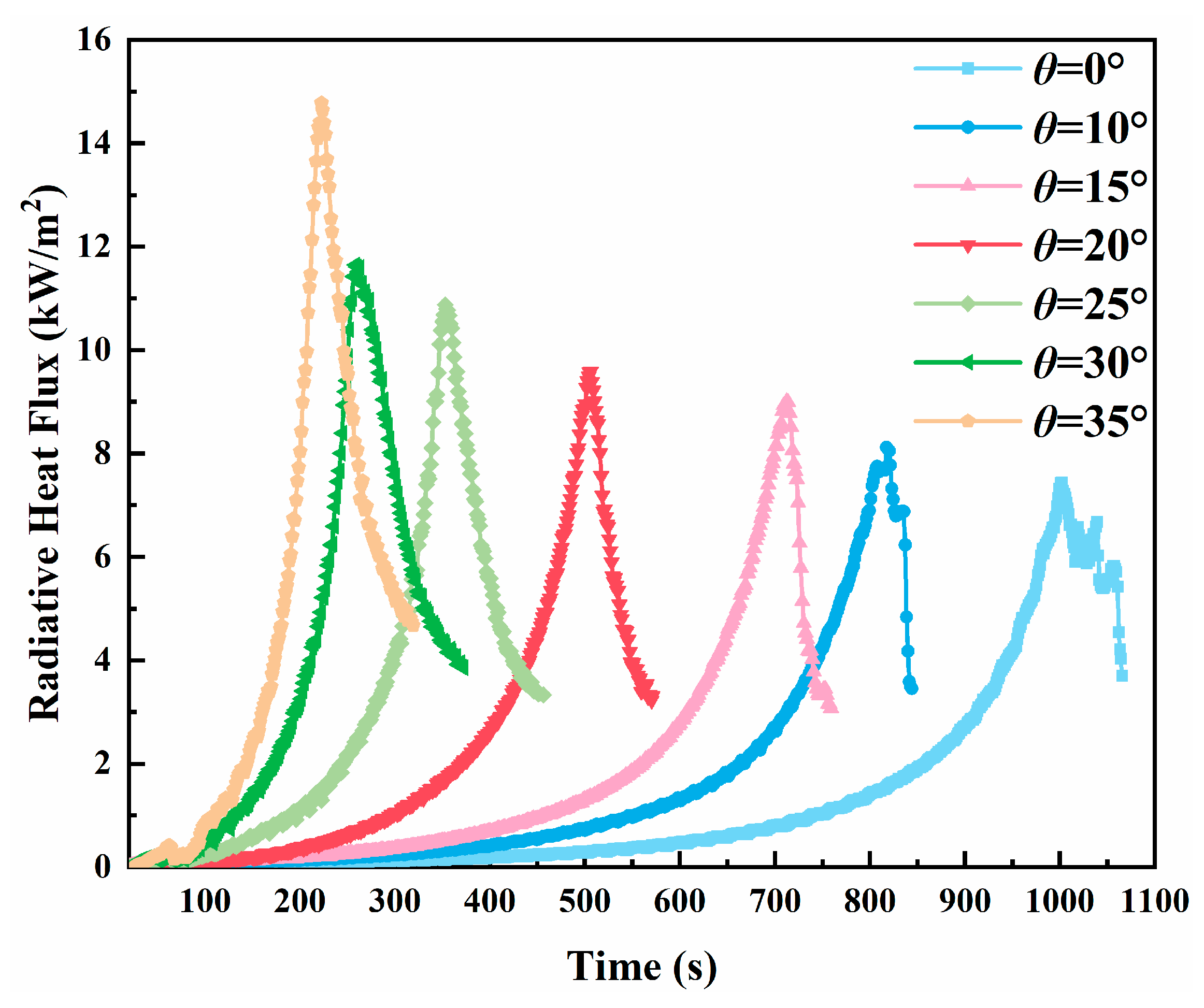
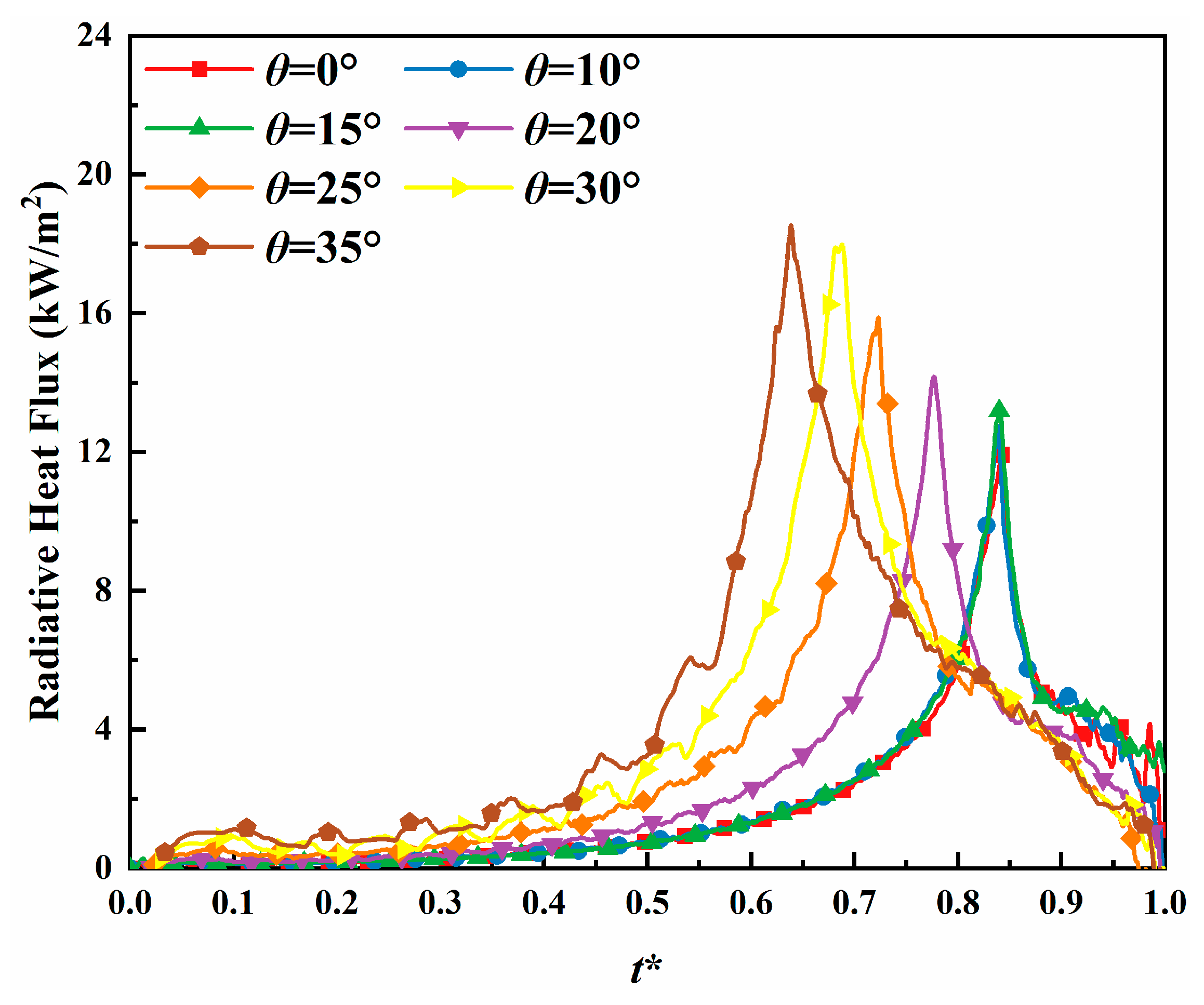
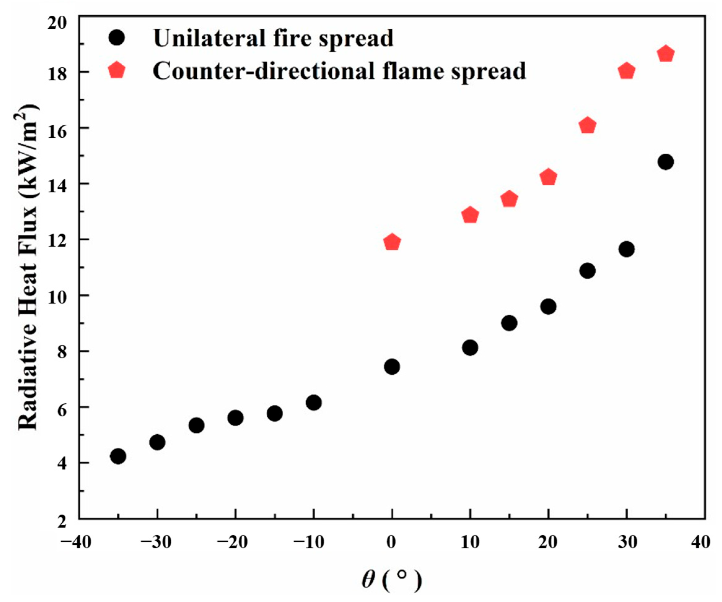
3.4. Radiative Heat Flux

The thermal dynamics of multi-fire systems exhibit significantly greater complexity than single-fire scenarios due to interactive heat transfer mechanisms between adjacent flames. Enhanced radiative heat feedback has been identified as a key governing mechanism for the distinctive combustion behavior in multiple-source fires [10]. To fundamentally understand the coupled combustion dynamics during slope-driven counter-directional flame propagation, investigation of radiative heat flux density variations becomes essential.
A comprehensive assessment of radiative heat feedback in counter-directional flame spread necessitates comparative analysis with unilateral flame propagation under identical slope conditions. In this section, radiative heat flux density profiles are numerically predicted for both propagation modes across varying slopes. As established in previous sections, slope effects significantly intensify combustion on the concurrent-flow side of counter-directional flames. Figure 13 presents the variation in radiative heat flux density during unilateral flame spread across the studied slope range. Both the simulated peak radiative heat flux density and its temporal evolution show strong slope dependence: peak values increase with slope angle, while time-to-peak decreases correspondingly. These trends are mechanistically attributed to slope-induced alterations in flame geometry, particularly via expansion of flame area and progressive tilting toward the solid fuel’s preheat zone. These morphological changes enhance radiative transfer to the unburned fuel surface, leading to increased simulated radiative heat flux values.
For counter-directional flame propagation, the flame merging position varies with slope inclination. The contact position of pyrolysis fronts serves as a key indicator for evaluating bilateral flame interaction effects. Radiative heat flux measurements were conducted at pyrolysis front contact points under varying slope conditions. Given the varying spread durations across different slopes, we normalized temporal evolution using dimensionless time t* to enable direct comparison of radiative heat flux development. Figure 14 presents the relationship between radiative heat flux density and dimensionless time at flame contact positions for different slope angles.
The radiative heat flux density variation in counter-directional flame propagation was analyzed in our previous study [26], revealing the dominant influence of view factor F. During initial propagation, flames exhibit quasi-independent combustion with minimal view factor (F remains nearly constant). As flame fronts converge during interaction, F increases progressively with growing flame tilt, peaking at flame tip fusion. Subsequent flame merging reduces both air coiling restriction and tilt angle, leading to a characteristic rise-and-decline pattern in radiative heat flux density at the pyrolysis front contact location.
Figure 15 compares the peak radiative heat flux densities for unilateral and counter-directional flame propagation at varying slopes. Both configurations exhibit similar increasing trends with slope angle, demonstrating consistent slope dependence. Due to radiative heat feedback enhancement, the peak radiative heat flux density of counter-directional flame spread exceeds that of unilateral fire spread at the same slope.

3.5. Analysis of the Effects of Flame Interactions

Flame interaction alters a fire source’s burning and spreading behavior, reflecting how other sources combine to affect it versus isolated burning [29]. To quantitatively evaluate the asymmetric interactions between concurrent-flow and counter-current sides, we introduce a dimensionless influence coefficient I(a) to quantify interaction intensity on side a:
I a = 1 t f t s a
where tf denotes the flame front contact time during counter-directional flame spread, while ts(a) represents the time taken for a unilateral fire to spread the same distance at the same slope as the counter-directional fire.
The fire spread is facilitated by flame interaction during counter-directional propagation; therefore, tf < ts(a). According to Equation (11), the value of I(a) varies between 0 and 1. A larger I(a) indicates a stronger influence of flame interaction on fire spread. When tf = ts(a), I(a) = 0, signifying that flame interaction has no effect on fire spread. The calculated I(a) values are listed in Table 5.
Analysis of the slope-dependent variation in I(a) reveals asymmetric flame interaction effects between propagation directions. The opposed-flow side demonstrates particularly strong interaction influence within the 20° to 35° slope range, where coupled combustion enhances flame spread processes significantly. Conversely, the concurrent-flow side exhibits progressively diminishing interaction effects with increasing slope, as evidenced by the reduction in I(a) values. This differential behavior highlights the orientation-dependent nature of flame interactions during counter-directional propagation.
The slope-dependent variation of I(a) can be analyzed from two perspectives. First, while an increasing slope facilitates concurrent-flow side propagation, it simultaneously reduces the relative contribution of flame interactions to this process, as evidenced by comparative mass loss rate measurements between unilateral and counter-directional cases. Second, the promotion effect of flame interactions on fire propagation mainly occurs through thermal feedback enhancement. With increasing slope magnitude, the concurrent-flow side exhibits intensified combustion and greater radiative heat flux, whereas the opposed-flow side demonstrates inverse characteristics. This asymmetric behavior results in differential thermal radiation effects: the concurrent-flow flame becomes less influenced by radiation from the opposed-flow side, while the opposed-flow side experiences significantly greater impact. Consequently, flame interactions exhibit more pronounced promotion effects on opposed-flow flame spread.

4. Conclusions

This study systematically investigated slope-dependent flame propagation characteristics on PMMA surfaces through comprehensive numerical simulations, comparing unilateral and counter-directional spread regimes. To resolve the asymmetrical interaction mechanisms observed in counter-directional spread, a quantitative analytical method was developed based on temporal flame spread variations, enabling characterization of flame interaction effects on both sides. Analysis of key fire parameters and propagation dynamics revealed several fundamental findings:
(1)
The morphological analysis of counter-directional flame propagation revealed distinct slope-dependent characteristics. While horizontal propagation (0° slope) exhibited symmetric flame structures on both sides, inclined conditions induced asymmetric flame development. This asymmetry manifested as two distinct flame regimes: a concurrent-flow side with enhanced flame attachment and tilt toward the fuel surface, and an opposed-flow side demonstrating reduced flame inclination and weaker fuel preheating. These morphological differences confirmed the fundamental counter-directional combustion phenomenon hypothesized in this study.
(2)
The propagation dynamics of counter-directional flames, including spread velocity and mass loss rate, exhibited significant dependence on inter-flame spacing during interaction phases. Both parameters showed progressive enhancement with slope, mirroring the behavior observed in peak radiative heat flux density for both unilateral and counter-directional propagation modes.

Author Contributions

Conceptualization, Q.L., K.L., C.Y., N.B. and Z.L.; methodology, Q.L., K.L., C.Y., N.B. and J.C.; software, K.L., C.Y., N.B. and W.X.; validation, Q.L.; formal analysis, K.L., C.Y., N.B. and W.X.; investigation, K.L.; resources, Q.L., C.Y. and N.B.; data curation, K.L. and J.C.; writing—original draft preparation, Q.L., K.L., C.Y., N.B. and Z.L.; writing—review and editing, Q.L., K.L., C.Y., N.B., Z.L., W.X. and J.C.; visualization, J.C.; supervision, Q.L. and Z.L.; project administration, Q.L. and Z.L.; funding acquisition, Q.L. and W.X. All authors have read and agreed to the published version of the manuscript.

Funding

The authors acknowledge the sponsorship from the Natural Science Foundation of Hunan Province (NO. 2025JJ50332) and the Fundamental Research Funds for the Central Universities of the Central South University (NO. 2025ZZTS0549).

Institutional Review Board Statement

Not applicable.

Informed Consent Statement

Not applicable.

Data Availability Statement

The original contributions presented in this study are included in the article. Further inquiries can be directed to the corresponding author.

Conflicts of Interest

The authors declare no conflicts of interest.

Abbreviations

The following abbreviations are used in this manuscript:
CFDComputational fluid dynamics
FDSFire dynamics simulator
fvDOMFinite volume Discrete Ordinates Model
NISTNational Institute of Standards and Technology
PMMAPolymethylmethacrylate
RTERadiative Transfer Equation

References

  1. Zhou, Y.; Xiao, H.H.; Sun, J.H.; Zhang, X.N.; Yan, W.G.; Huang, X.J. Experimental study of horizontal flame spread over rigid polyurethane foam on a plateau: Effects of sample width and ambient pressure. Fire Mater. 2015, 39, 127–138. [Google Scholar] [CrossRef]
  2. Gao, Y.; Zhu, G.; Zhu, H.; An, W.; Xia, Y. Experimental study of moisture content effects on horizontal flame spread over thin cotton fabric. Text. Res. J. 2019, 89, 3189–3200. [Google Scholar] [CrossRef]
  3. Li, C.; Liao, Y.T.T. Numerical investigation of flame splitting phenomenon in upward flame spread over solids with a two-stage pyrolysis model. Combust. Sci. Technol. 2018, 190, 2082–2096. [Google Scholar] [CrossRef]
  4. Luo, S.; Xie, Q.; Qiu, R. Melting and dripping flow behaviors on the downward flame spread of a wide XPS foam. Fire Technol. 2019, 55, 2055–2086. [Google Scholar] [CrossRef]
  5. Honda, L.K.; Ronney, P.D. Mechanisms of concurrent-flow flame spread over solid fuel beds. Proc. Combust. Inst. 2000, 28, 2793–2801. [Google Scholar] [CrossRef]
  6. Drysdale, D.D.; Macmillan, A.J.R. Flame spread on inclined surfaces. Fire Saf. J. 1992, 18, 245–254. [Google Scholar] [CrossRef]
  7. Quintiere, J.G. The effects of angular orientation on flame spread over thin materials. Fire Saf. J. 2001, 36, 291–312. [Google Scholar] [CrossRef]
  8. Zhang, Y.; Li, Q.; Tang, K.; Lin, Y. Surface inclination effects on heat transfer during flame spread acceleration based on FireFOAM. Case Stud. Therm. Eng. 2022, 32, 101905. [Google Scholar] [CrossRef]
  9. Huang, Y.; Hu, L.; Ma, Y.; Zhu, N.; Chen, Y.; Jonathan, W.; Margaret, M.; Patrick, H. Experimental study of flame spread over thermally-thin inclined fuel surface and controlling heat transfer mechanism under concurrent wind. Int. J. Therm. Sci. 2021, 165, 106936. [Google Scholar] [CrossRef]
  10. Liu, N.; Liu, Q.; Deng, Z.; Kohyu, S.; Zhu, J. Burn-out time data analysis on interaction effects among multiple fires in fire arrays. Proc. Combust. Inst. 2007, 31, 2589–2597. [Google Scholar] [CrossRef]
  11. Viegas, D.X.; Raposo, J.R.; Davim, D.A.; Rossa, C.G. Study of the jump fire produced by the interaction of two oblique fire fronts. Part 1. Analytical model and validation with no-slope laboratory experiments. Int. J. Wildland Fire 2012, 21, 843–856. [Google Scholar] [CrossRef]
  12. Zhang, X.; Hu, L.; Zhang, X.; Yang, L.; Wang, S. Non-Dimensional correlations on flame height and axial temperature profile of a buoyant turbulent line-source jet fire plume. J. Fire Sci. 2014, 32, 406–416. [Google Scholar] [CrossRef]
  13. Zhang, X.; Xu, W.; Hu, L.; Liu, X.; Zhang, X.; Xu, W. A new mathematical method for quantifying trajectory of buoyant line-source gaseous fuel jet diffusion flames in cross air flows. Fuel 2016, 177, 107–112. [Google Scholar] [CrossRef]
  14. Jiang, L.; Zhao, Z.; Tang, W.; Miller, C.; Sun, J.-H.; Gollner, M.J. Flame spread and burning rates through vertical arrays of wooden dowels. Proc. Combust. Inst. 2019, 37, 3767–3774. [Google Scholar] [CrossRef]
  15. Joshi, A.K.; Kumar, A.; Raghavan, V.; Trubachev, S.A.; Shmakov, A.G.; Korobeinichev, O.P.; Kumar, B.P. Numerical and experimental study of downward flame spread along multiple parallel fuel sheets. Fire Saf. J. 2021, 125, 103414. [Google Scholar] [CrossRef]
  16. Peng, F.; Zhou, X.D.; Zhao, K.; Wu, Z.B.; Yang, L.Z. Experimental and numerical study on effect of sample orientation on auto-ignition and piloted ignition of poly (methyl methacrylate). Materials 2015, 8, 4004–4021. [Google Scholar] [CrossRef]
  17. Ranga, H.R.; Korobeinichev, O.P.; Harish, A.; Raghavan, V.; Kumar, A.; Gerasimov, I.E.; Gonchikzhapov, M.B.; Tereshchenko, A.G.; Trubachev, S.A.; Shmakov, A.G. Investigation of the structure and spread rate of flames over PMMA slabs. Appl. Therm. Eng. 2018, 130, 477–491. [Google Scholar] [CrossRef]
  18. Chatterjee, P.; Wang, Y.; Meredith, K.V.; Dorofeev, S.B. Application of a subgrid soot-radiation model in the numerical simulation of a heptane pool fire. Proc. Combust. Inst. 2015, 35, 2573–2580. [Google Scholar] [CrossRef]
  19. Zeinali, D.; Gupta, A.; Maragkos, G.; Agarwal, G.; Beji, T.; Chaos, M.; Wang, Y.; Degroote, J.; Merci, B. Study of the importance of non-uniform mass density in numerical simulations of fire spread over MDF panels in a corner configuration. Combust. Flame 2019, 200, 303–315. [Google Scholar] [CrossRef]
  20. Ito, A.; Kashiwagi, T. Characterization of flame spread over PMMA using holographic interferometry sample orientation effects. Combust. Flame 1988, 71, 189–204. [Google Scholar] [CrossRef]
  21. Gou, F.H.; Xiao, H.H.; Jiang, L.; Li, M.; Zhang, M.M. Upward flame spread over an array of discrete thermally-thin PMMA plates. Fire Technol. 2021, 57, 1381–1399. [Google Scholar] [CrossRef]
  22. Stoliarov, S.I.; Crowley, S.; Lyon, R.E.; Linteris, G.T. Prediction of the burning rates of non-charring polymers. Combust. Flame 2009, 156, 1068–1083. [Google Scholar] [CrossRef]
  23. Bhattacharjee, S.; King, M.D.; Paolini, C. Structure of downward spreading flames: A comparison of numerical simulation, experimental results and a simplified parabolic theory. Combust. Theory Model. 2003, 8, 23. [Google Scholar] [CrossRef]
  24. Huang, X.; Liu, W.; Chen, G.; Wang, C.; Tang, G.; Zhang, H. Flame Spread Characteristics over Building Decoration Material of PMMA with Different Placed Angles. Chin. J. Process Eng. 2018, 18, 454–460. [Google Scholar]
  25. Zhang, Y.; Ji, J.; Wang, Q.; Huang, X.; Wang, Q.; Sun, J. Prediction of the critical condition for flame acceleration over wood surface with different sample orientations. Combust. Flame 2012, 159, 2999–3002. [Google Scholar] [CrossRef]
  26. Liu, Q.; Bian, N.; Zhang, R.; Li, Z.; Shi, L. Experimental study on coupled combustion of PMMA counter-directional flame spread in the horizontal direction. Exp. Therm. Fluid Sci. 2023, 143, 110850. [Google Scholar] [CrossRef]
  27. Xie, W.; DesJardin, P.E. An embedded upward flame spread model using 2D direct numerical simulations. Combust. Flame 2009, 156, 522–530. [Google Scholar] [CrossRef]
  28. Liu, Q.; Du, B.; Yan, Q.; Shi, L.; Li, M.; Li, Z. Study on coupled combustion behavior of two parallel line fires. Fire 2022, 5, 14. [Google Scholar] [CrossRef]
  29. Liu, N.; Liu, Q.; Lozano, J.S.; Shu, L.; Zhang, L.; Zhu, J.; Deng, Z.; Satoh, K. Global burning rate of square fire arrays: Experimental correlation and interpretation. Proc. Combust. Inst. 2009, 32, 2519–2526. [Google Scholar] [CrossRef]
Figure 1. Computational domain for counter-directional flame spread.
Fire 08 00219 g001
Figure 2. Comparison of flame instantaneous lengths measured under different grid size conditions with experimental results [24].
Fire 08 00219 g002
Figure 3. Comparison of numerical simulation and experimental [24] flame morphology of unilateral fire spread on different slopes.
Fire 08 00219 g003aFire 08 00219 g003b
Figure 4. Comparison of numerical simulation and experimental [24] results for different slope flame tilt angles.
Fire 08 00219 g004
Figure 5. Comparison of fire spread rate between numerical simulation and experiment [6,9] under different slope conditions.
Fire 08 00219 g005
Figure 6. Schematics of flame morphological evolution during counter-directional flame spread under slope conditions: (a) initial ignition phase; (b) flame interaction phase; (c) fully merged flame stage.
Fire 08 00219 g006
Figure 7. Flame morphology evolution during unilateral flame spread under varying slopes.
Fire 08 00219 g007
Figure 8. Flame morphology evolution during counter-directional flame spread under varying slope conditions.
Fire 08 00219 g008
Figure 9. Counter-directional flame spread rate variation under varying slopes.
Fire 08 00219 g009
Figure 10. Single-sided versus counter-directional flame spread rates: (a) θ = 0°; (b) θ = 10°; (c) θ = 15°; (d) θ = 20°; (e) θ = 25°; (f) θ = 30°.
Fire 08 00219 g010aFire 08 00219 g010b
Figure 11. Mass loss rate profiles for (a) counter-directional and (b) unilateral flame spread under varying slopes.
Fire 08 00219 g011
Figure 12. Stage division of fire propagation based on flame spread rate and mass loss rate trends: (a) 0° ≤ θ ≤ 15°, (b) 20° ≤ θ ≤ 35°.
Fire 08 00219 g012aFire 08 00219 g012b
Figure 13. Radiative heat flux density of unilateral fire spread under varying slopes (midpoint of PMMA specimen).
Fire 08 00219 g013
Figure 14. Radiative heat flux density of counter-directional flame spread under varying slopes (Pyrolysis front interface).
Fire 08 00219 g014
Figure 15. Variation of peak radiative heat flux density for unilateral and counter-directional flame spread at different slopes.
Fire 08 00219 g015
Table 1. Properties of PMMA [22,23].
ParametersUnitsValue
Densitykg/m31190
Specific heatkJ/kg/K2.2
ConductivityW/m/K0.2
Emissivity0.85
Absorption coefficientm−12700
Pre-exponential factors−18.5 × 10¹²
Activation energykJ/kmol1.88 × 105
Heat of reactionkJ/kg870
Table 2. Values of g(x) and g(z).
θ (°)g(x) (m/s2)g(z) (m/s2)θ (°)g(x) (m/s2)g(z) (m/s2)
0−9.8125°4.146−8.891
10°1.704−9.66130°4.905−8.496
15°2.539−9.47635°5.627−8.036
20°3.355−9.218
Table 3. Specific calculation areas and grid settings.
Forms of Fire SpreadCalculation Area (x, y, z)Number of Grids
Unilateral fire spread25 cm × 5 cm × 10 cm156,250
Counter-directional flame spread25 cm × 5 cm × 15 cm234,375
Table 4. Flame front contact time under different slopes and fire spread distance on both sides upon flame contact.
SlopeContact Time of
the Flame Front
Fire Spread Distance on
the Concurrent-Flow Side
Fire Spread Distance on
the Opposed-Flow Side
917.81010
10°884.3128
15°832.3137
20°661.714.65.4
25°502.416.23.8
30°392.517.22.8
35°329.617.82.2
Table 5. Dimensionless influence coefficients for different slope conditions.
SlopeI(a)-Concurrent-Flow SideI(a)-Opposed-Flow Side
0.083480.08348
10°0.077510.08458
15°0.066810.08599
20°0.065260.1267
25°0.056170.14061
30°0.052390.18821
35°0.052060.20636
Disclaimer/Publisher’s Note: The statements, opinions and data contained in all publications are solely those of the individual author(s) and contributor(s) and not of MDPI and/or the editor(s). MDPI and/or the editor(s) disclaim responsibility for any injury to people or property resulting from any ideas, methods, instructions or products referred to in the content.

