
Improvement in Fire Resistance and Smoke Leakage Performance for Existing Polyvinyl Chloride Pipes Passing Through Walls


Abstract
1. Introduction
2. Experimental Details
2.1. Furnace
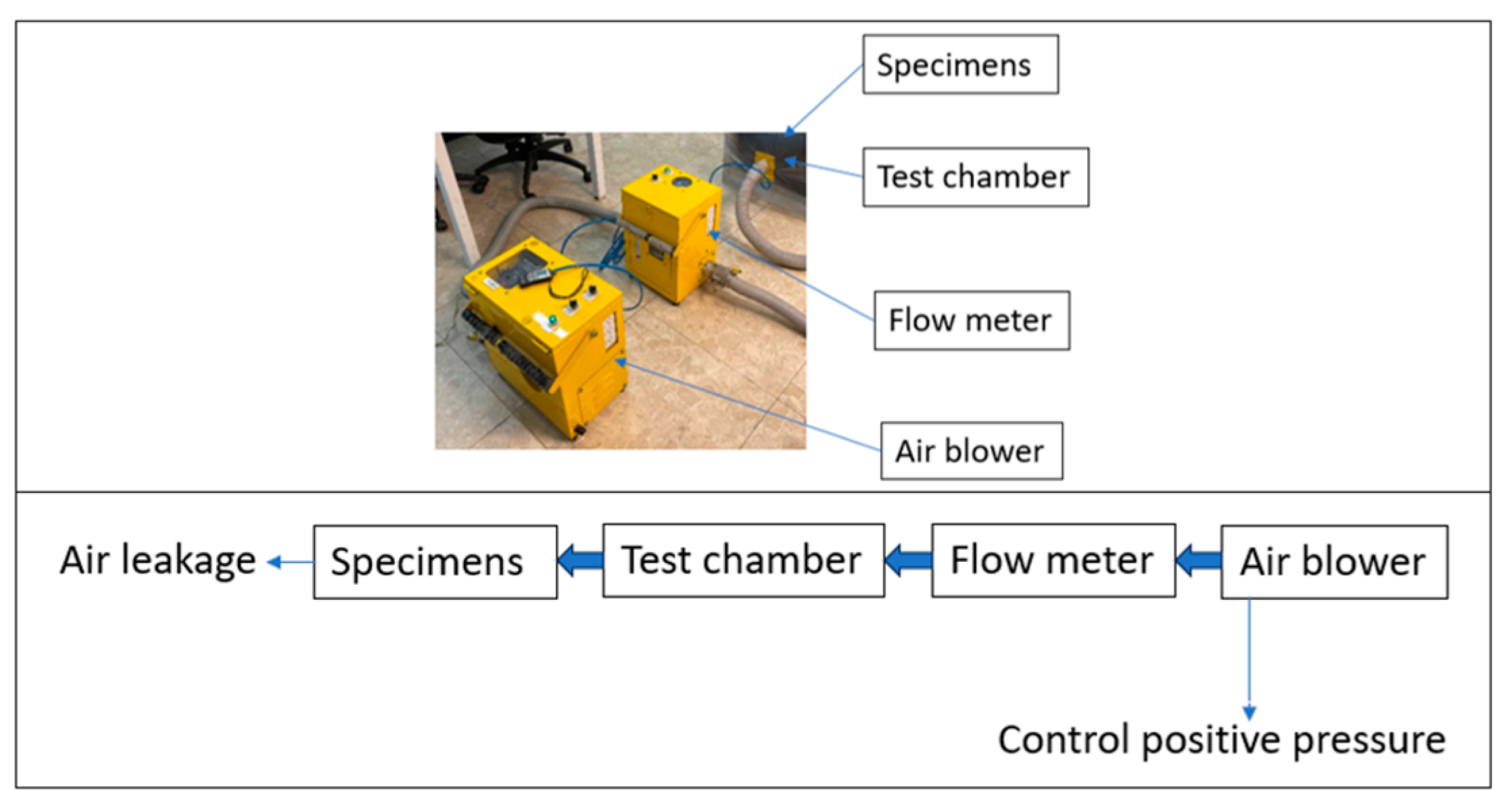
2.2. Smoke Leakage Test Apparatus
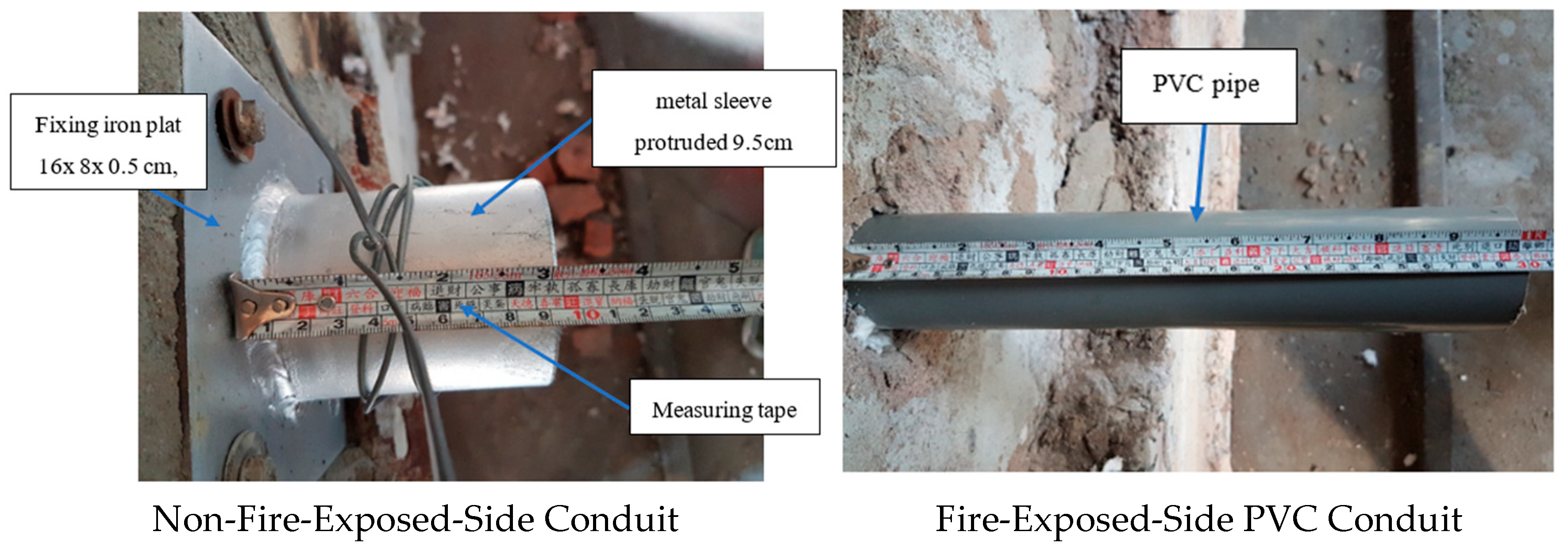
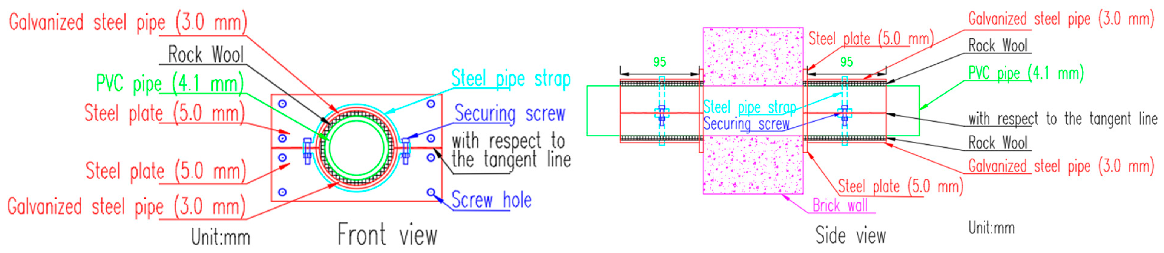
2.3. Test Specimens
2.4. Test Procedure
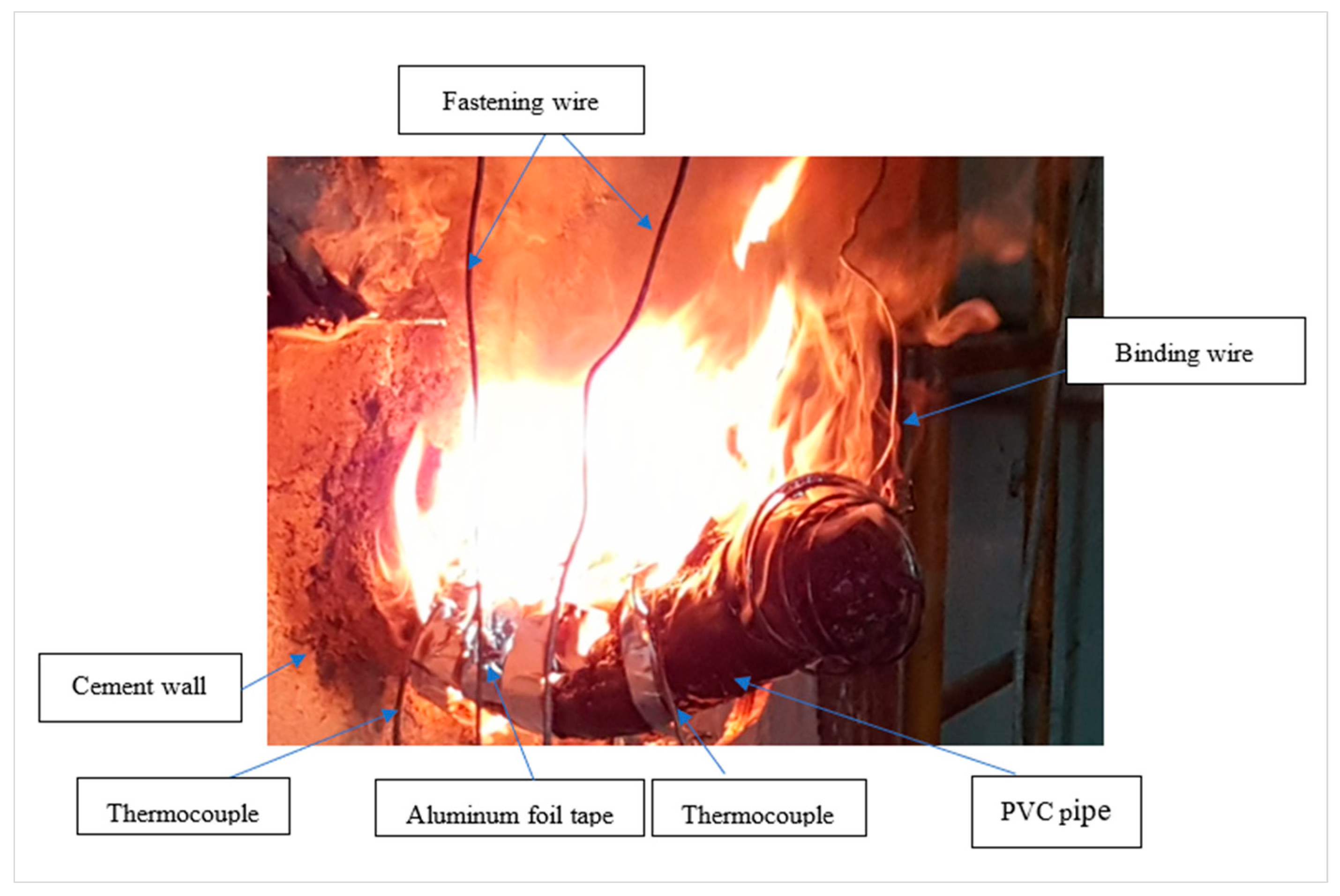
2.4.1. Fire Tests
- (1)
- de ≦ 15% 5 < t ≦ 10;
- (2)
- de = 15 − 0.5 × (t − 10)% 10 < t ≦ 30;
- (3)
- de = 5 − 0.083 × (t − 30)% 30 < t ≦ 60;
- (4)
- de = 2.5% t > 60;
2.4.2. Smoke Leakage Tests
3. Results
3.1. Smoke Leakage Tests Result
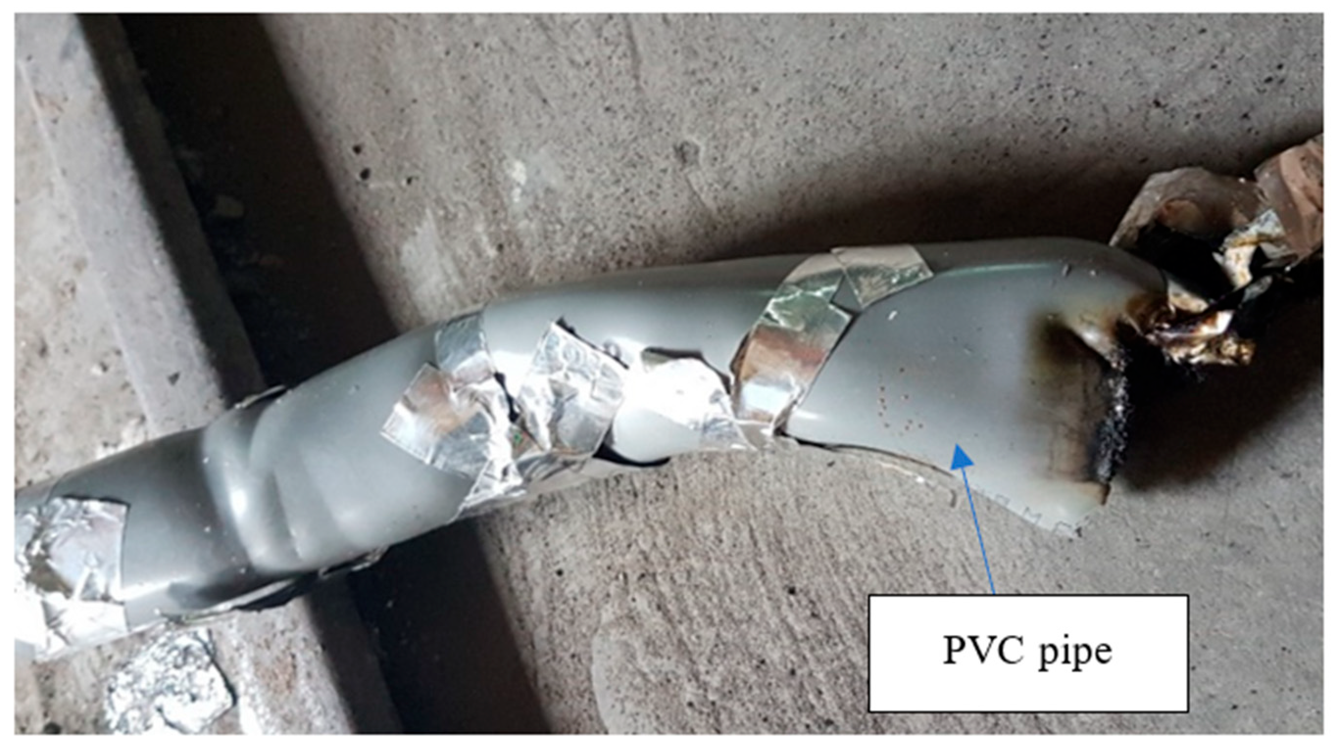
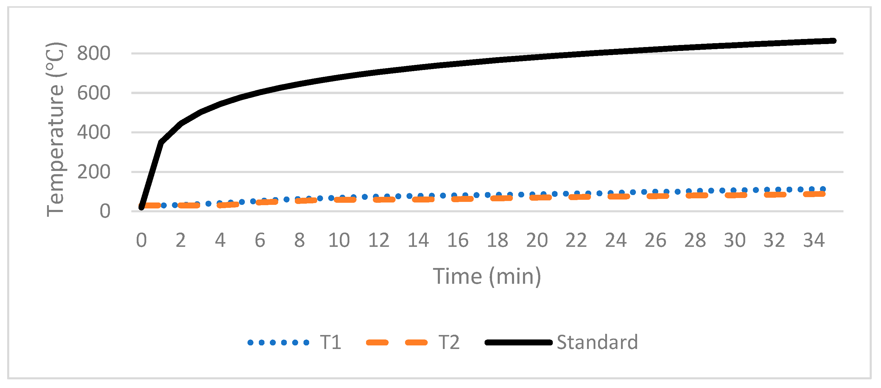
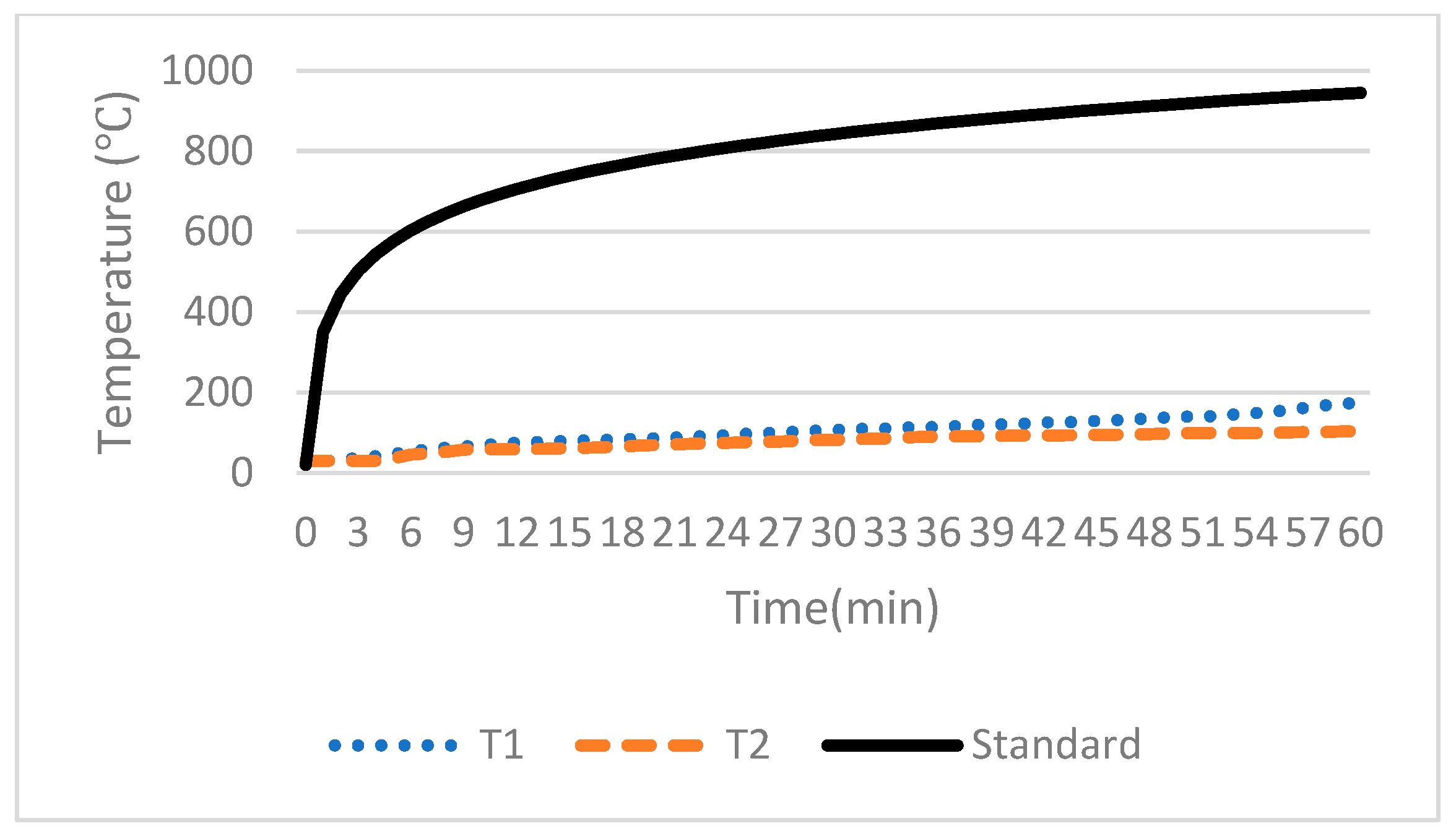
3.2. Fire Tests Result
- During the 1 h heating test, no openings formed that could lead to the ignition of the cotton pad or allow the penetration of the measurement gauge.
- During the 1 h heating test, no sustained flames lasting longer than 10 s appeared on the side unexposed to the fire.
- During the 1 h heating test, the average temperature on the unexposed side did not exceed the initial average temperature of 140 °C, and the temperature at any given point did not exceed the initial average temperature of 180 °C.
4. Discussion
5. Conclusions
- In smoke leakage tests, a PVC pipe with a metal sleeve (specimen A2-S) exhibited considerably lower leakage rates than did a PVC pipe without a metal sleeve (specimen A1-S) under pressure differentials of 10, 25, and 50 Pa. This result is attributable to the metal sleeve, which allowed for a larger quantity of rock wool to be packed into the gap between the sleeve and the PVC pipe, which effectively prevented gas flow to the other side. The leakage rate of specimen A2-S was up to 90% lower than that of specimen A1-S.
- In fire resistance tests, specimen A1-S had a fire resistance duration of approximately 35 min, whereas specimen A2-S had a fire resistance duration exceeding 60 min. Thus, the metal sleeve enhances the fire resistance of the PVC pipe. The metal sleeve also contributed to improved safety. PVC pipes exposed to high temperatures in a fire may melt, thus compromising fire compartmentation. The presence of a metal sleeve helps contain the melted part of the PVC pipe within the sleeve, preventing the pipe from falling and causing injuries or igniting other materials.
- In this study, the metal sleeve was installed only on the side of the wall that was not exposed to the fire; nevertheless, the sleeve still considerably improved the smoke leakage performance and fire resistance of the PVC pipe. However, because a fire can occur on either side of a wall, metal sleeves are recommended to be installed on both sides of the wall in practical scenarios.
- Metal sleeves are recommended to be installed using a half-sleeve design. The primary function of a metal sleeve is to support a PVC pipe and accommodate rock wool insulation. Therefore, as long as the two parts of the metal sleeve are securely fixed to the wall, a half-sleeve design is feasible in practical construction.
- The smoke leakage test used in this study can be used to evaluate and ensure the integrity of smoke compartmentation. Moreover, this test can be employed to assess the ambient-temperature smoke leakage performance of penetrations after installation.
Author Contributions
Funding
Institutional Review Board Statement
Informed Consent Statement
Data Availability Statement
Acknowledgments
Conflicts of Interest
References
- Ye, Z.; Fleischmann, C.M.; Abu, A.K.; Pau, D. Estimation of effective thermophysical properties of firestopping sealants: Methodology and case study. Fire Saf. J. 2023, 141, 103928. [Google Scholar] [CrossRef]
- CNS 15814-1; Fire Tests for Building Elements and Components—Fire Testing of Service Installations—Part 1: Penetration Seals. Bureau of Standard, Metrology and Inspection (BSMI): Taipei, Taiwan, 2015.
- ISO 10295-1:2007; Fire Tests for Building Elements and Components—Fire Testing of Service Installations, Part 1: Penetration Seals. ISO: Geneva, Switzerland, 2007.
- SS-EN 1366-3:2021+A1:2025; Fire Resistance Tests for Service Installations, Part 3: Penetration Seals. GB-BSI: London, UK, 2021.
- GB 23864 -2009; Firestop material. Ministry of Public Security: Beijing, China, 2009.
- UL 1479; Standard Method of Fire Tests Through-Penetration Firestops. UL: Chicago, IL, USA, 1985.
- ASTM E814; Standard Test Method for Fire Tests of Penetration Firestop Systems. ASTM International: West Conshohocken, PA, USA, 2017.
- Gill, P.; Martin, R.V. Smoke inhalation injury. BJA Educ. 2015, 15, 143–148. [Google Scholar] [CrossRef]
- Klote, J.H. Smoke Control. In SFPE Handbook of Fire Protection Engineering; Springer: New York, NY, USA, 2006; pp. 1785–1823. [Google Scholar]
- Chou, T.L.; Tang, C.H.; Chuang, Y.J.; Lin, C.Y. Study on Smoke Leakage Performance of Suspended Ceiling System. Sustainability 2020, 12, 7244. [Google Scholar] [CrossRef]
- Department of Land Administration, Ministry of the Interior, R.O.C. (Taiwan), Taiwan Building Technical Regulations, National Association of Architects R.O.C. (Taiwan), Taipei, Taiwan, 2025.
- Hung, H.Y.; Lin, C.Y.; Chuang, Y.J.; Luan, C.P. Application Development of Smoke Leakage Test Apparatus for Door Sets in the Field. Fire 2022, 5, 12. [Google Scholar] [CrossRef]
- CNS 5534-1982; Thermocuples. Bureau of Standard, Metrology and Inspection (BSMI): Taipei, Taiwan, 1982.
- Chuang, Y.H.; Chuang, Y.J.; Lin, C.Y. Using a new testing method to measure smoke leakage of existing doors. J. Appl. Fire Sci. 2006, 16, 21–33. [Google Scholar] [CrossRef]
- Kuo, S.Y.; Tseng, Y.T.; Chuang, Y.J. Comparison of Test Apparatus for Determining the Smoke Leakage Rate of Fire Doors. J. Food Agric. Environ. 2013, 11, 2831–2841. [Google Scholar]
- CNS 15038; Method of test for evaluating smoke control performance of doors. Bureau of Standard, Metrology and Inspection (BSMI): Taipei, Taiwan, 2010.
- Hung, H.-Y.; Chuang, Y.-J.; Lin, C.-Y. Enhancing refuge space safety: Tape application to reduce door leakage during fires, Advances in civil engineering. Adv. Civ. Eng. 2024, 2024, 2064541. [Google Scholar]
- Chang, W.Y.; Lin, C.Y.; Chuang, Y.J.; Tsai, M.T. Study on smoke leakage performance in mass timber construction taking cross-laminated timber walls as an example. Fire 2025, 8, 42. [Google Scholar] [CrossRef]
- Liu, S.H.; Lin, C.Y.; Chuang, Y.J. Study of relationships between ceiling smoke leakage rate and evacuation time in the ward. Int. J. Environ. Res. Public Health 2021, 18, 13280. [Google Scholar] [CrossRef] [PubMed]
- Lin, B.S.M.; Lin, C.Y.; Kung, C.W.; Lin, Y.J.; Chou, C.C.; Chuang, Y.J.; Hsiao, G.L.K. Wayfinding of firefighters in dark and complex environments. Int. J. Environ. Res. Public Health 2021, 18, 8014. [Google Scholar] [CrossRef] [PubMed]


Disclaimer/Publisher’s Note: The statements, opinions and data contained in all publications are solely those of the individual author(s) and contributor(s) and not of MDPI and/or the editor(s). MDPI and/or the editor(s) disclaim responsibility for any injury to people or property resulting from any ideas, methods, instructions or products referred to in the content. |
© 2025 by the authors. Licensee MDPI, Basel, Switzerland. This article is an open access article distributed under the terms and conditions of the Creative Commons Attribution (CC BY) license (https://creativecommons.org/licenses/by/4.0/).
Share and Cite
Li, T.-Y.; Chuang, Y.-J.; Lin, C.-Y.; Chao, T.-W. Improvement in Fire Resistance and Smoke Leakage Performance for Existing Polyvinyl Chloride Pipes Passing Through Walls. Fire 2025, 8, 202. https://doi.org/10.3390/fire8050202
Li T-Y, Chuang Y-J, Lin C-Y, Chao T-W. Improvement in Fire Resistance and Smoke Leakage Performance for Existing Polyvinyl Chloride Pipes Passing Through Walls. Fire. 2025; 8(5):202. https://doi.org/10.3390/fire8050202
Chicago/Turabian StyleLi, Ting-Yuan, Ying-Ji Chuang, Ching-Yuan Lin, and Tseng-Wei Chao. 2025. "Improvement in Fire Resistance and Smoke Leakage Performance for Existing Polyvinyl Chloride Pipes Passing Through Walls" Fire 8, no. 5: 202. https://doi.org/10.3390/fire8050202
APA StyleLi, T.-Y., Chuang, Y.-J., Lin, C.-Y., & Chao, T.-W. (2025). Improvement in Fire Resistance and Smoke Leakage Performance for Existing Polyvinyl Chloride Pipes Passing Through Walls. Fire, 8(5), 202. https://doi.org/10.3390/fire8050202