3.1. General Temperature Distributions of the Electrode During the DC Arcing
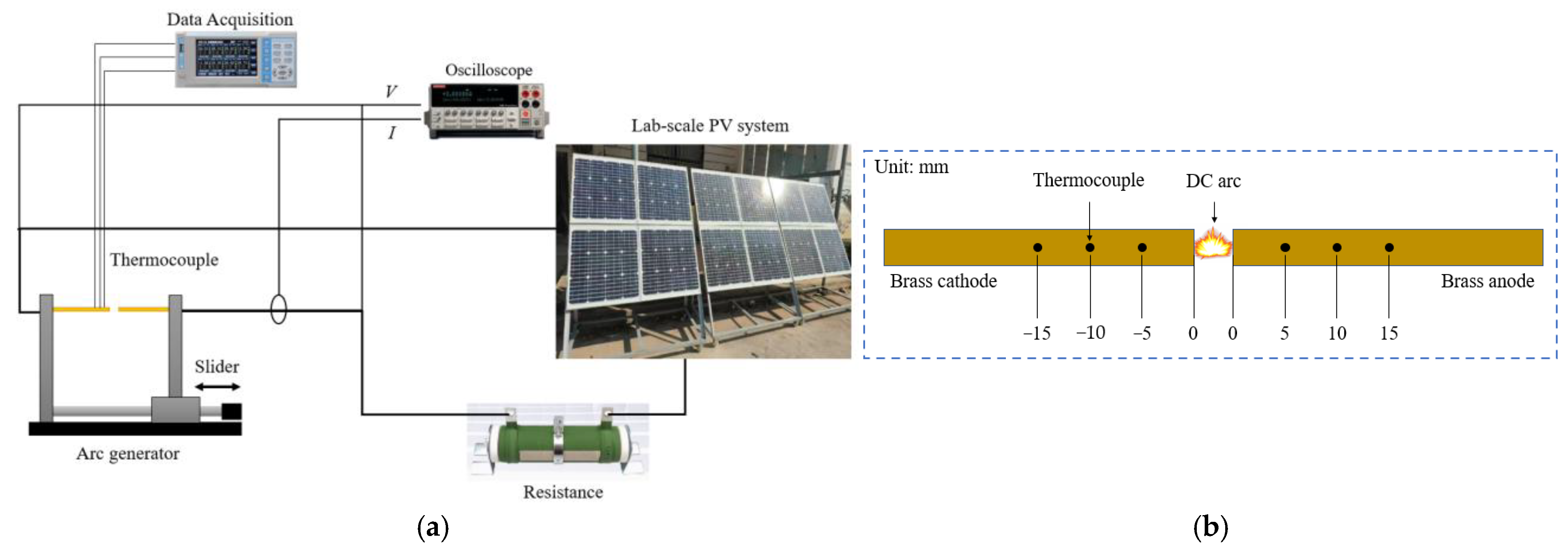
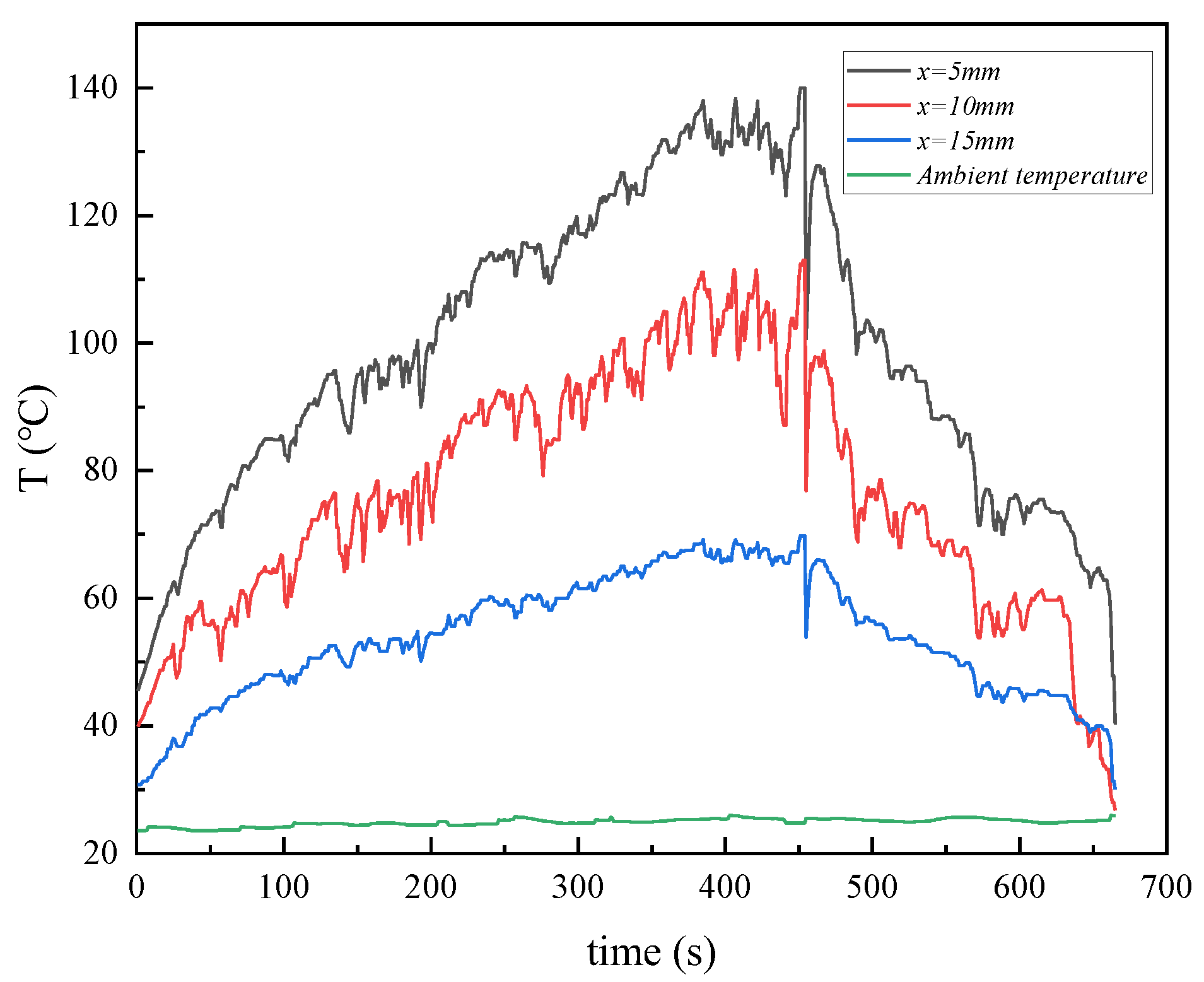
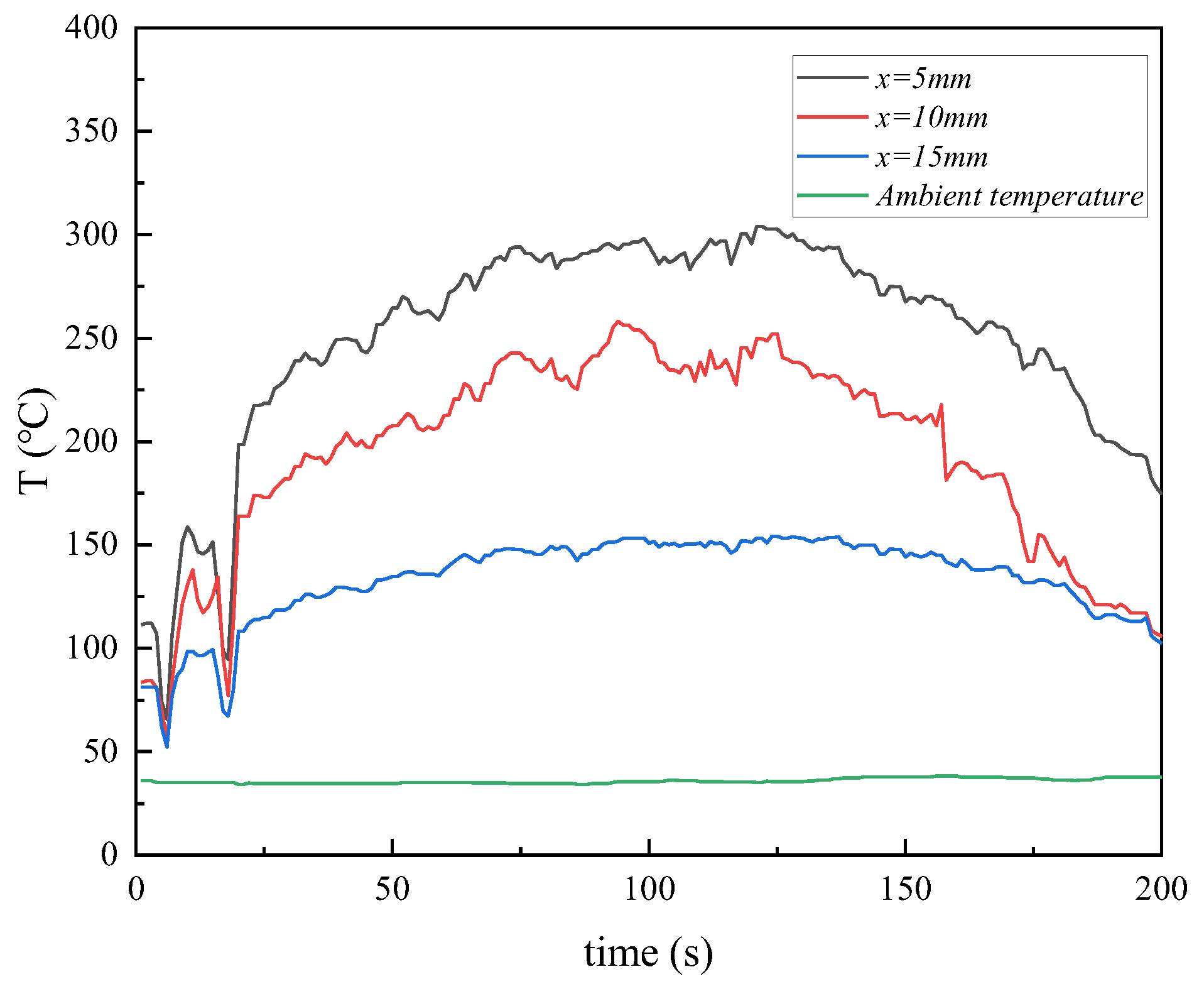
Figure 2 illustrates variations in electrode surface temperatures during the occurrence of a DC arc generated by the lab-scale PV system with the energy output of 244 V and 0.27 A. The ambient temperature, serving as a baseline reference, remains stable at about 25 °C throughout the measurement. As shown in the figure, the temperature rise is most pronounced at the closest measured location, which is 5 mm from the arc, where the peak temperature approaches around 140 °C. Specifically, within the first 200 s, the temperature increases rapidly and then fluctuates at a high level. When the power is cut off around 460 s, the temperature gradually decreases due to the lack of thermal input from the DC arcs. This indicates the significant thermal impact of the DC arc on areas near the arc source owing to the fast heat transfer to the electrode surface through conduction and radiation, which causes the sustained heating in the local area.
Compared to the position at 5 mm, the rise rate and peak value of temperature are comparatively lower at the position of 10 mm, with a peak temperature of about 110 °C, while the temperature curve still shows a similar trend with relatively obvious fluctuations. The temperature fluctuations indicate the still-intense thermal impact of DC arcs, while the lower temperatures suggest the heat transfer attenuation at this slightly farther distance. At the position of 15 mm, the temperature rise is even slower, with a peak temperature of only around 65 °C. This suggests that heat transfer at this distance should be primarily through conduction, with minimal direct influence from arc radiation. The smaller temperature fluctuations imply the reduced thermal influence of DC arcs and a relatively stable thermal distribution in this area.
As a result, the electrode surface temperature decreases rapidly with increasing distance from the arc source, indicating a significant reduction in thermal impact at farther distances. The notable heating effects at the 5 mm and 10 mm positions from the arc highlight the intensive local heating caused by the high energy released by the DC arc. At 15 mm, the attenuation trend of thermal effect can be determined by the arc’s energy radiation range, the mode of heat propagation in the medium, and the thermal conductivity of the electrode material. Among these factors, the thermal conductivity of the electrode material should play a crucial role, as it dominates the efficiency and speed of heat transfer from the arc source to the electrode surface. Moreover, it is noted that more fluctuating temperature data indicate the great instability of DC arcs in real PV systems. The significant thermal effects caused by the DC arc indicate its potential severe hazards, leading to fire accidents.
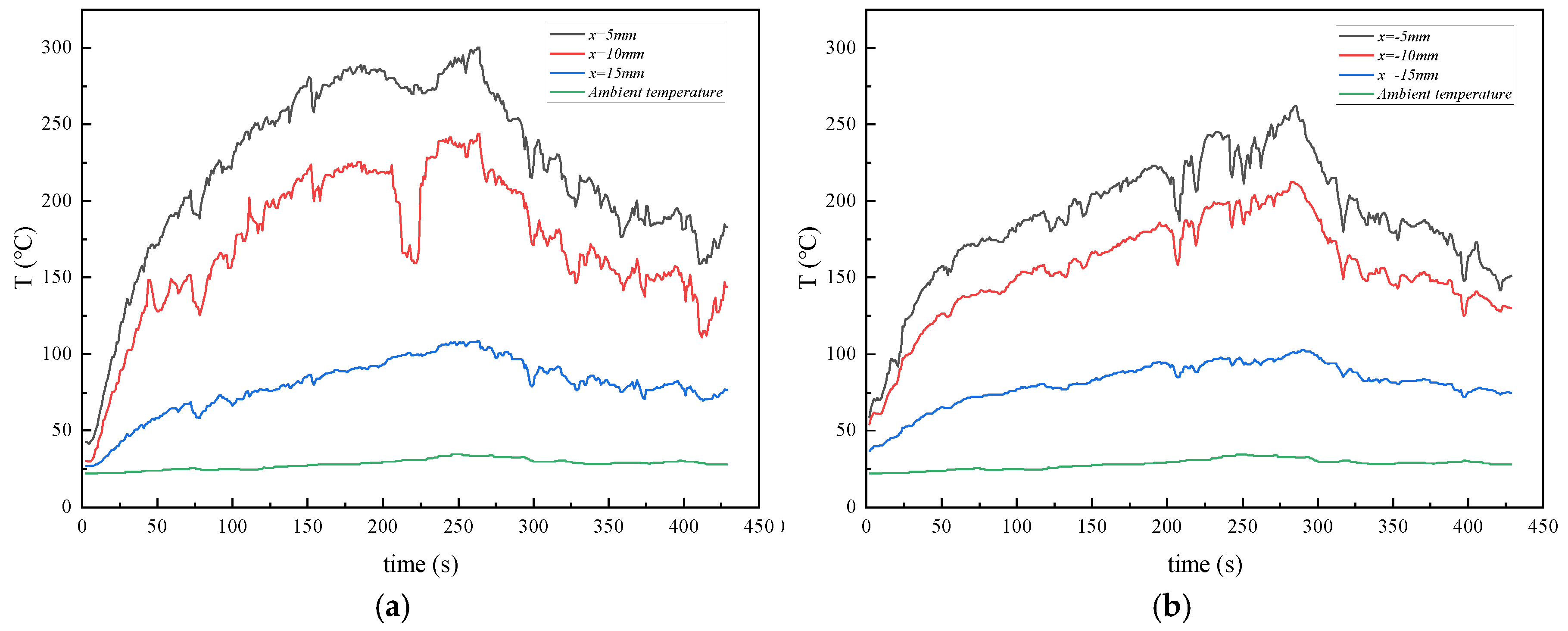
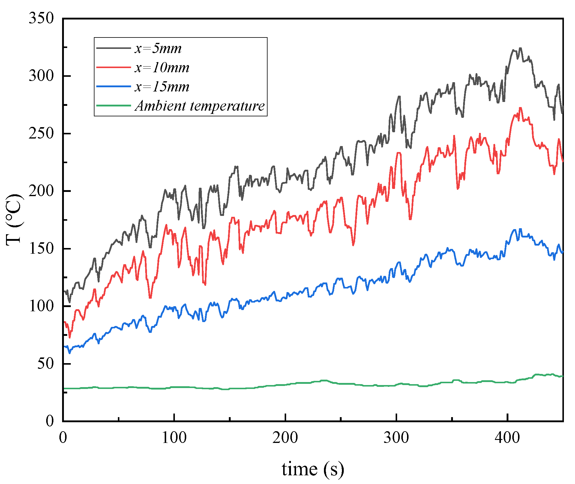
For the PV system under a condition of 244 V and 3.2 A, the surface temperature variations of positive and negative electrodes are compared in
Figure 3. It is seen that, during the DC arcing process, the electrode surface temperature peaks in the negative electrode region (−5 mm, −10 mm, −15 mm) are generally lower than those in the positive electrode region (5 mm, 10 mm, 15 mm). Additionally, the temperature distributions of positive/negative electrodes exhibit similar variation trends. The closer the distance to the DC arc, the faster the temperature rises, and the higher the peak temperature. Specifically, at the 5 mm position near the DC arc on the positive electrode, the temperature increases rapidly and reaches a peak of nearly 300 °C, accompanied by significant fluctuations. This indicates that the closer area is strongly affected by direct heat conduction and radiation from the DC arc. As the distance increases, the peak temperature gradually decreases to approximately 230 °C at the 10 mm position, while it drops to about 100 °C at the 15 mm position. In contrast, the maximum temperature peak in the negative electrode region is about 250 °C at the −5 mm position, while the lowest temperature peak at the −15 mm position has a similar level to that at the 15 mm position. It is thus concluded that, either in the positive or negative electrode regions, rapid temperature attenuation trends with the increased distance always exist, which further confirms that the thermal effect of the DC arc prefers to concentrate around the DC arc and diminishes effectively with distance owing to the cooling effects of ambient air.
Furthermore, it is noted that there exist obvious differences in thermal effects between the positive and negative electrodes owing to the different temperatures at the same distances away from the DC arc, as shown in
Figure 3, such as at 5 mm and −5 mm positions. This indicates more significant heat accumulation in the positive electrode region, which can be caused by more effective heat transfer and particle collision, accompanied by the electron flow toward the positive electrode. Due to the higher temperatures and large fluctuations in the positive electrode region, the physical and chemical properties of the materials may be affected more significantly. Particularly under stable high-intensity DC arc conditions, the structural stability and durability of the positive electrode material may decline more notably than the negative side. By contrast, for the negative electrode region, although the heat accumulation is relatively weaker, the potential long-term thermal aging of materials due to DC arcs should not be neglected in real PV systems. Moreover, the higher temperatures in the positive electrode region also imply higher fire risks for the components connected to the positive terminal of the PV system. As a result, for PV systems, special attention might be paid to optimizing the heat resistance of connectors in the positive electrode region in order to improve system reliability and prevent fire occurrence.
3.2. Effects of Current on Electrode Temperatures During the DC Arcing
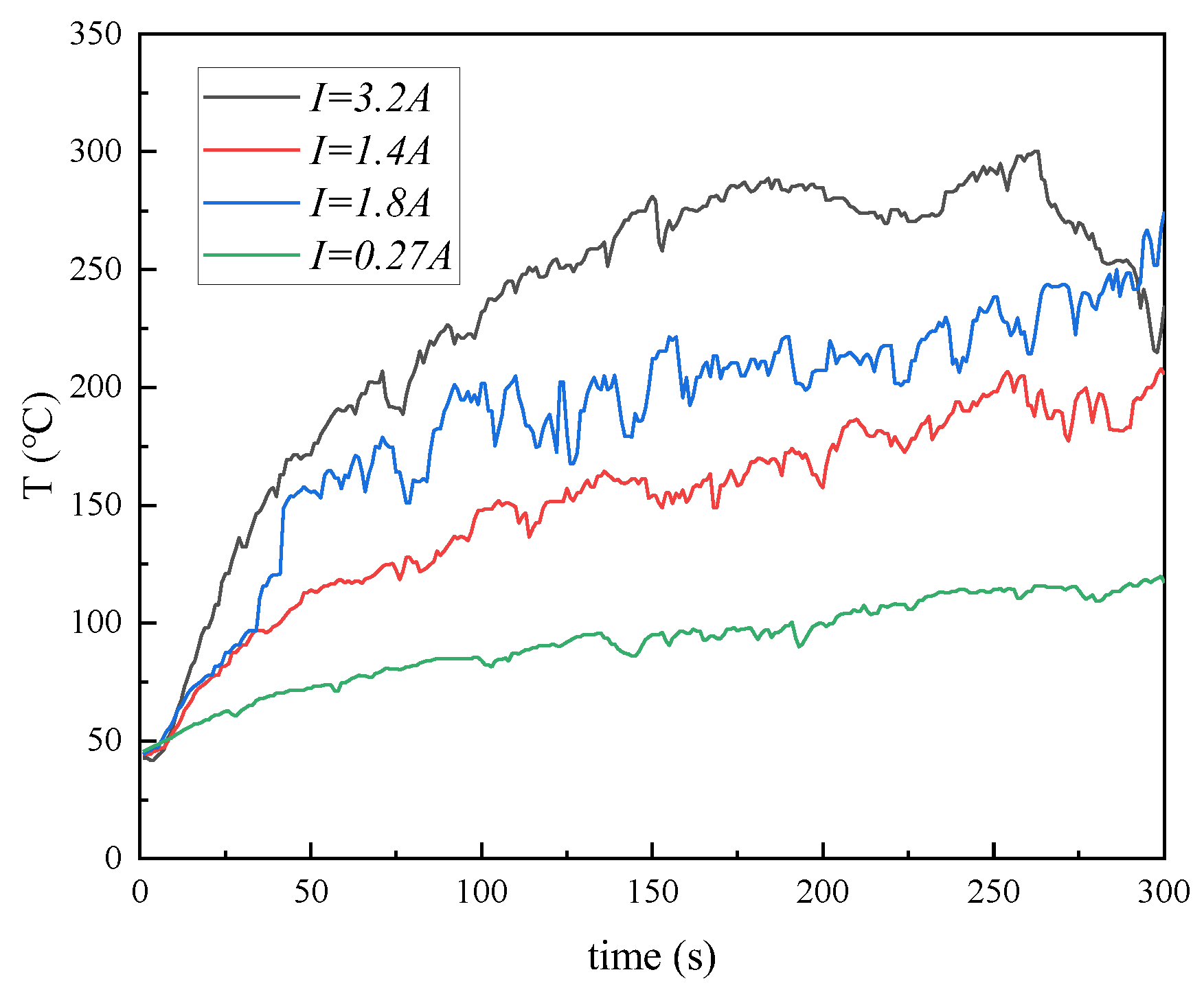
Figure 4 illustrates the variations in the electrode surface temperature with the varied current input at a constant position of the positive electrode. To examine the effects of varying current, measurements are conducted on the lab-scale PV system at different times of the day, and then four distinct current conditions (3.2 A, 1.8 A, 1.4 A, and 0.27 A) are produced for investigating the thermal effects of DC arcs. As shown in
Figure 4, with a current of 3.2 A, the temperature rises the fastest and reaches the highest peak. Within the first 50 s of the sustained DC arc, the temperature sharply increases to approximately 180 °C. The temperature continues to rise at a slower rate, reaching the peak value of about 300 °C, eventually at around 260 s. Additionally, the temperature curve shows more evident fluctuations after 100 s, which may be caused by coupling effects of the dynamic instability of the DC arc, changes in the DC arc channel, and the uneven local heat conduction. Furthermore, as the current is decreased steadily, the rising trend of temperature within the first 50 s becomes increasingly moderate, while the peak temperature is also decreased to about 70 °C at a current of 0.27 A during the measurement period. It is thus known that the larger current intensifies the heat release process of the DC arc effectively, causing the local area of the electrode to endure strong heat accumulation effects.
Considering that the current of real PV systems is variable with changes in environmental conditions, there exists a need to investigate the dynamic impact of current variations on the thermal effects of DC arcs on electrodes. This can provide a comprehensive understanding of the thermal characteristics of DC arcs. To quantify the effects of current variability, experimental measurements are carried out under cloudy sky conditions, which can induce continuous current changes in the PV system owing to the natural irradiance fluctuations. The dynamic responses of surface temperatures to the continuous decreased/increased current in the tested PV system are illustrated in
Figure 5 and
Figure 6. As shown in
Figure 5, as the current is varied from a high value to a low value, accompanied by the stable DC arc, the electrode surface temperature does not exhibit a simple linear decline but rather shows an initial rising trend followed by a gradual decrease. Throughout the current variation process, the temperature curve over time exhibits a distinct peak interval, where the electrode surface temperature reaches its highest value under a certain medium current condition. In contrast, when the current increases gradually, the temperature variation trend of the electrode shows an approximately linear upward trend without a noticeable temperature peak, as shown in
Figure 6.
Generally, the heat generated by a DC arc is proportional to the square of the current passing through it. Therefore, changes in current can directly affect the heat transfer state and temperature distribution of the electrode. When the accumulation and dissipation rates of heat in the electrode are not balanced perfectly, the electrode′s ability to reach thermal equilibrium can be influenced considerably, which thereby affects the variation trends of electrode surface temperatures. This finally predominates the significant differences in temperature variation trends under different current change paths, as shown in
Figure 5 and
Figure 6. Specifically, when the current decreases continuously to a low level, the initial high current results in a substantial amount of heat generated by the DC arc, causing a quite high rate of heat accumulation in the electrode during the initial stage. As the current decreases gradually, the heat generation rate is reduced steadily while the heat dissipation rate is accelerated comparatively. However, the large amount of heat generated by the DC arc in the early stages is still sufficient to maintain a rapid upward trend in the electrode surface temperature until the current drops to a certain level. Under this condition, the balance between the heat dissipation and the heat generation is reached, and then the temperature begins to decline gradually owing to the further reduced heat generation by the continuously decreased current. As a result, this thermal hysteresis effect should be the main reason for the nonlinear variation trend of surface temperature with the dynamically reduced current. By contrast, when the current increases steadily during the DC arc process, the heat generated by the DC arc increases progressively with the increased current, leading to an increasingly effective heat accumulation process in the electrode. However, the heat dissipation rate could maintain a relatively steady level after an initial acceleration owing to the relatively stable ambient cooling effects. Consequently, the electrode surface temperature shows a steady linear rising trend with the dynamically increased current during the DC arc process, as shown in
Figure 6. Overall, dynamic fluctuations in the current of a PV system can exert complex effects on the thermal performance of a DC arc. With the sustained DC arcs, the dynamic balance point between the heat accumulation and dissipation changes continuously with the varied current, predominating the complex evolution of the DC arc and resulting in the nonlinear temperature variation trend in the electrode.
Based on the above measured data, it is known that the current plays a crucial role in the temperature rise trend of electrodes during the DC arcing process. Higher currents give rise to strong thermal effects of the DC arc, causing a rapid increase in electrode temperature accompanied by significant temperature fluctuations. Such intense thermal effects can have profound impacts on material properties, which can cause thermal fatigue, local damage, and microstructure degradation of the electrode material. In contrast, under lower current conditions, even though the thermal effects of the DC arc are weakened significantly, the comparatively stable DC arcing process can still lead to the continuous heat accumulation in local areas and then the higher local temperature of the electrode. This can also exert a significant influence on the material properties of connectors. Apart from this, considering the quite high temperature distributions of the electrodes under either high or low current conditions, the thermal effects caused by the DC arc can always pose potentially severe risks of localized ignition and fire accidents in the PV systems.
3.3. Effects of the Electrode Gap on Temperatures During the DC Arcing
During the DC arcing, the thermal effects can lead to the melting of metal components, causing a larger gap between connectors. The analysis of the thermal performance of the DC arc with the increased gap can improve the understanding of the dynamic variations of the DC arc and help to evaluate risks of DC arcing.
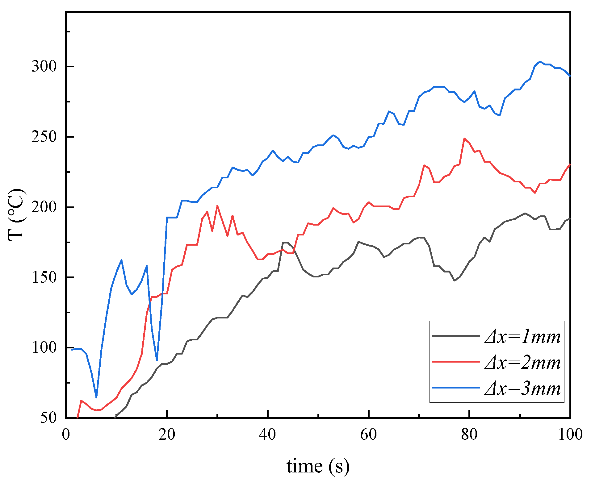
Figure 7 illustrates the temperature variations at the 5 mm position of the positive electrode under 244 V and 3.2 A conditions at different electrode gaps (∆
x = 1 mm, 2 mm, 3 mm). The experimental data indicate that the electrode gap significantly affects the rise rate of temperature, temperature peak, and temperature fluctuations.
When the electrode gap is 1 mm, the electrode surface temperature rises relatively slowly and reaches the lowest peak value of about 170 °C at 100 s. During the rising trend, the comparatively smaller fluctuations can be observed. Furthermore, as the electrode gap increases to 2 mm or 3 mm, the increasing rate and peak value of temperature are both enhanced significantly, with the peak values reaching about 220 °C/280 °C at 100 s. Furthermore, temperature fluctuations become more obvious compared to those at the 1 mm gap. These variations can be explained briefly as follows. In shorter electrode gaps, due to the smaller length of the DC arc, the spatial diffusion range of heat is limited considerably. Meanwhile, the lower equivalent resistance of the DC arc results in relatively less heat release during the DC arcing. This results in comparatively moderate but more uniform localized heating of the electrode, which finally leads to the lower peak value and relatively less fluctuations of the electrode surface temperature during the arcing process in shorter gaps, as shown in
Figure 7. As the electrode gap is increased, the increased DC arc length brings about the increased resistance and then the significantly increased heat release by the DC arc. This can contribute to the faster rise and higher maximum value of the surface temperature, as shown in
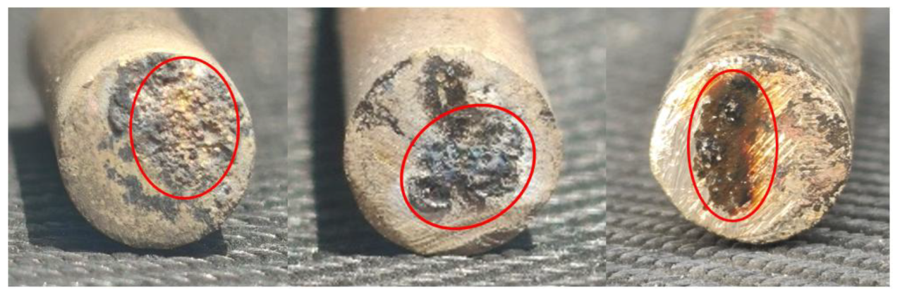
Figure 7. Besides, it is noted that although the larger electrode gaps can lead to the increased thermal energy release, the increased arc length can weaken its stability during the DC arcing, owing to airflow disturbances and arc flickering exacerbating the unevenness of heat transfer. This leads to the relatively larger fluctuations of electrode temperature and may give rise to localized overheating of the electrode, as shown in
Figure 8. Specifically, the crater and black ablation marks within the red circles in
Figure 8 are the results of localized high-temperature effects caused by DC arcing.
3.4. Ignition Characteristics of the DC Arcs
To further evaluate the thermal effects of DC arc and its potential fire risks in PV systems, the ignition times of typical materials used in PV systems are measured to gain useful knowledge of the DC arc characteristics in real PV systems. By using the lab-scale PV system under the condition of 244 V and 1.2 A, some materials commonly used in PV system components are adopted to measure their ignition times during the DC arcing, including polyphenylene ether (PPE), polycarbonate (PC), silicone rubber, cross-linked polyolefin (XLPO), polyvinyl chloride (PVC), and polyethylene (PE). The fundamental properties of these electrical materials are given in
Table 1. Additionally, paper and leaves, two materials commonly found in the surrounding environment of PV systems, are also chosen to study their ignition characteristics during the DC arcing. These materials not only cover various electrical insulation materials of common PV system components but also consider some potential combustible materials in the environment. This can provide more valuable data support for a comprehensive investigation of the ignition capability of DC arcs, which can then provide useful theoretical guidance and practical basis for the safety design and risk assessment of PV systems.
As shown in
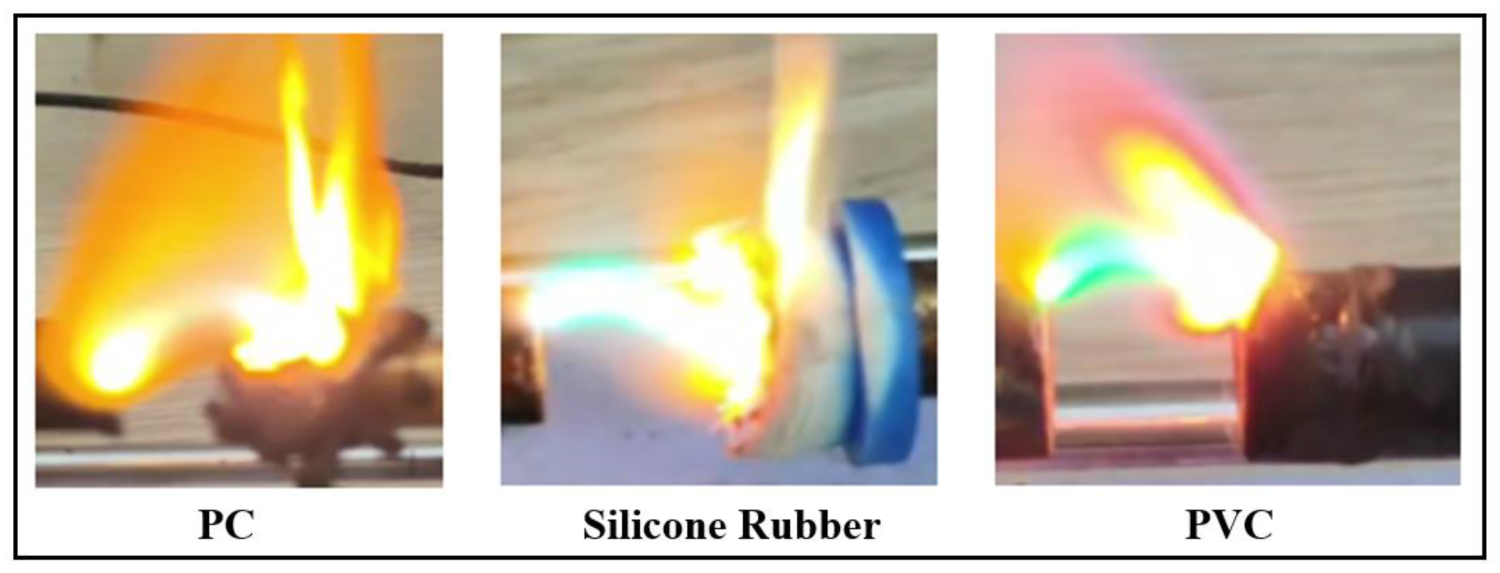
Figure 9, under the measured condition of 244 V and 1.2 A, all materials are ignited successfully by the DC arc, and visible flames can be observed and sustained. Despite excellent anti-ignition properties under normal conditions, flame-retardant materials (such as PPE, XLPO, and silicone rubber) all ignited comparatively easily, owing to the sustained high-temperature and high-energy effects of the sustained DC arcs. Furthermore, it is observed that these flame-retardant materials typically produce visible flames within seconds to tens of seconds as they are exposed to the DC arc. After the ignition, the open flame can be highly persistent, indicating that the heat transfer and energy input from the intensive DC arc exceed the critical values of their flame-retardant performance. More specifically, high-energy DC arcs deliver localized heat fluxes that exceed the thermal resistance limits of flame-retardant components. Although these components initially inhibit combustion through endothermic reactions and radical quenching, the sustained arc energy can disrupt their protective mechanisms by continuously breaking polymer bonds and releasing flammable volatiles. Once pyrolysis begins, the process becomes self-sustaining: heat transfer from both the arc and nascent flames accelerates the degradation of adjacent materials. This finally leads to the sustained flames, despite the presence of inherent flame-retardant properties. In contrast, materials like paper and leaves commonly existed in the environment exhibit obvious flammability. During the DC arcing process, these materials can be ignited in a relatively short time (within about 6 s) and then form bright flames quickly. The rapid ignition should be mainly caused by the relatively low ignition temperature and comparatively high volatility of these materials. For materials tested in this study, with the coupling effects of thermal radiation and conduction from the DC arc, the combustible components in the materials decompose rapidly and react with oxygen in the air to form the sustained open flames. For the better clarification, critical time points for the ignition processes of these tested materials are provided in
Table 2.
Additionally, to better clarify the effects of variable conditions in the PV system on the ignition processes of different materials, the ignition times of these materials are also measured under the condition of 243 V and 2.9 A. As illustrated in
Table 2 and
Table 3, the ignition times of the tested materials are reduced significantly. For example, the ignition times of PC and PVC decrease considerably from around 30 s to approximately 10 s. Based on the earlier investigation of the current’s effects on electrode surface temperatures, it is known that higher currents enhance the heat release capability of DC arcs, thereby significantly increasing the electrode surface temperature. This leads to a notable reduction in the ignition times of these materials, as shown in
Table 2 and
Table 3. Hence, these results further confirm that higher currents can substantially increase the ignition risks associated with DC arcs in PV systems.
Moreover, it is noted that the ignition times of PPE and XLPO materials are significantly shorter by an order of magnitude compared to other materials, as shown in
Table 2. Additionally, even under the higher current condition as shown in
Table 3, these two materials still exhibit much longer ignition times than under the relatively lower current condition as shown in
Table 2. This is attributed to the fact that these two materials are in direct contact with the positive electrode during the DC arcing under the condition of 244 V and 1.2 A (
Table 2). As discussed earlier, the positive electrode region of the DC arc has a much higher temperature due to its more effective heat accumulation effect. This not only significantly increases the surface temperature of the materials but also accelerates the reaction of combustible gases produced by the material decomposition with the higher temperature environment, eventually leading to the extremely rapid ignition of the materials. It is thus known that, once a DC arc occurs in actual PV systems, the risks of ignition and flame spread can be much higher in the positive electrode region than the negative electrode region.
Overall, under high voltage and large current conditions, a stable DC arc can not only ignite insulating and sealing materials quickly in PV systems but also has a high possibility of inducing sustained open flames to ignite other combustible materials in the surrounding environment. The ignition capability of such high-energy DC arcs on different materials is closely related to the material’s pyrolysis characteristics, surface thermal conductivity, and flame-retardant properties. It is noteworthy that, under relatively lower current conditions, although the time required to ignite different materials becomes longer, the heat accumulation effect of the sustained DC arc on the materials still has a high possibility of resulting in the open flame phenomenon. This can also obviously increase the potential risks of further flame propagation and then trigger the larger-scale fire spread.
The material loss after the ignition can increase the connector gap during the DC arcing, which can influence the DC arc characteristics effectively, and then the ignition features. In consideration of this, the effects of increased electrode gaps on the ignition processes of DC arcs on different materials are investigated in this part. As shown in
Figure 10, when the ignited materials are moved away gradually with the increased electrode gap, the DC arcing is not weakened but intensified significantly, accompanied by the greater brightness and stability. Furthermore, it is noted that the flames of the ignited materials also become more intense after increasing the electrode distance. This indicates that the increased electrode distance does not weaken the energy transfer of the DC arc but instead further strengthens its thermal effects.
This phenomenon could be codetermined by the self-stabilizing characteristics of a DC arc and its complex dynamic interaction with the surrounding environment. When the electrode distance increases, the electric field strength gradient between the two poles of the DC arc increases, which gives rise to higher ionization efficiency within the DC arc and generates more plasma particles. These high-energy plasma particles can maintain and enhance the heat generation of the DC arc, allowing the DC arc to remain stable over longer distances. Additionally, the volatile gases released during the combustion of ignited materials may also play an important role. These gases not only provide additional conductive channels for the DC arc but also supply chemical energy to sustain its high-temperature environment, which contributes to the enhanced brightness and temperature of the DC arc. Meanwhile, the enhanced DC arc can also promote the flames of the ignited materials significantly. The high temperature and strong thermal radiation effects brought by the stretched DC arc can accelerate the volatilization and oxidation reactions of combustible components on the material surface. This can thus contribute to the increased size and rapid spread of flames, which can then accelerate the ignition of other flammable materials, as shown in
Figure 10.
This phenomenon indicates that the increased electrode gap due to the consumption of materials may further intensify the DC arcing, which can, in turn, promote the open flame, eventually posing a higher risk of fire spread through the mutual promotion of open flame and the DC arc.


