Review

The Progress of Autoignition of High-Pressure Hydrogen Gas Leakage: A Comprehensive Review

1
College of Pipeline and Civil Engineering, China University of Petroleum (East China), No. 66, Changjiang West Road, Qingdao 266580, China
2
PetroChina Qinghai Oilfield Company Gas Production Plant, No. 3, Dunhuang 736200, China
*
Authors to whom correspondence should be addressed.
Fire 2024, 7(8), 268; https://doi.org/10.3390/fire7080268
Submission received: 23 June 2024 / Revised: 15 July 2024 / Accepted: 24 July 2024 / Published: 2 August 2024

Abstract

:
As a paradigm of clean energy, hydrogen is gradually attracting global attention. However, its unique characteristics of leakage and autoignition pose significant challenges to the development of high-pressure hydrogen storage technologies. In recent years, numerous scholars have made significant progress in the field of high-pressure hydrogen leakage autoignition. This paper, based on diffusion ignition theory, thoroughly explores the mechanism of high-pressure hydrogen leakage autoignition. It reviews the effects of various factors such as gas properties, burst disc rupture conditions, tube geometric structure, obstacles, etc., on shock wave growth patterns and autoignition characteristics. Additionally, the development of internal flames and propagation characteristics of external flames after ignition kernels generation are summarized. Finally, to promote future development in the field of high-pressure hydrogen energy storage and transportation, this paper identifies deficiencies in the current research and proposes key directions for future research.

1. Introduction

At present, fossil fuels are still the dominant source of energy. The use of large amounts of fossil fuels not only depletes fuel reserves but also gradually increases environmental pollution. To address this issue, prioritizing the development of clean energy has emerged as a critical strategy. Hydrogen is currently at the center of energy transformation because it is efficient, non-polluting, and inexhaustible for a foreseeable period of time [1]. The vigorous development of hydrogen energy is very useful for the current stage of energy demand as well as the current situation of environmental pollution.
Since the concept of the “Hydrogen Economy” was first introduced in 1970, numerous developed countries and regions have conducted extensive research on hydrogen energy and associated technologies [2], leading to rapid advancements in the production, storage, transportation, and application technologies of hydrogen [3]. Hydrogen storage, as an indispensable part of the hydrogen energy industry, plays a crucial role. Therefore, safe and economical hydrogen storage technology is key to propelling the development of the hydrogen energy industry. There are varieties of hydrogen storage technologies, each with its unique characteristics. High-pressure gaseous hydrogen storage is characterized by its low cost, reduced energy demands, and ease of deoxygenation under wide operating conditions. However, it faces limitations such as limited storage capacity and the need for pressure-resistant containers, and risks including hydrogen escape and vessel explosion. In contrast, low-temperature liquid hydrogen offers high-density storage, 845 times that of its gaseous state, enabling efficient storage and transport, but its energy demand and cost are high. Metal hydride hydrogen storage is safe and convenient, with simple hydrogen charging, but it is characterized by high material cost. The energy demand of various hydrogen storage schemes [4] is detailed in Table 1, from which it can be found that high-pressure gaseous hydrogen storage has the lowest energy demand per unit mass and is also the most economical.
Hydrogen is extremely accident-prone because of its many properties that are not conducive to safety. First, hydrogen can easily penetrate into material, leading to a reduction in the material’s mechanical performance and thus causing hydrogen leakage [5]. By analyzing 120 hydrogen accidents and their statistical data from a U.S. Department of Energy-supported accident database, Yang et al. [6] found that tube breakage and joint/valve accidents are the primary forms of hydrogen accidents. Hydrogen embrittlement and facility fatigue are the dominant factors in accidents. Secondly, hydrogen has a low ignition energy in air (0.017 mJ), a wide flammability range (4–74%), a broad explosion limit (11–59%), and a low theoretical critical ignition pressure (1.63 MPa) [7,8,9,10]. This can easily cause fires and explosions in case of leakage in various aspects of production, transportation, storage, and use, thus causing serious accident consequences. Therefore, sufficient safety with hydrogen energy is the key to ensuring its further popularization and development as a public civilian energy source. The safety concerns surrounding hydrogen energy have been a top international research priority and a significant barrier to its promotion [11,12,13].
As shown in Table 2, up to 86.3% [14] and 61.98% [15] of hydrogen fire incidents had no identified ignition source, indicating that fires can occur without an apparent cause. For hydrogen fire accidents where the ignition source is not identified, it is generally accepted that the spontaneous combustion of leaking high-pressure hydrogen occurs after hydrogen embrittlement or failure of the pressure relief device in a high-pressure hydrogen storage system.
To summarize, it is imperative to conduct in-depth research on the unique combustion phenomenon of autoignition triggered by the release of high-pressure hydrogen. Particular focus should be placed on the kinetic mechanism, criticality criteria, and microdynamic process leading to the formation of a stabilized jet flame. This will facilitate a comprehensive understanding of the complex mechanisms and principles involved, providing essential data and theoretical support for preventing autoignition caused by the release of high-pressure hydrogen and ensuring the safe design of hydrogen energy systems. Furthermore, establishing scientific and reasonable safety standards and regulations is crucial for advancing the realization of a clean, safe, efficient, and sustainable hydrogen energy economy.

2. Mechanism of Autoignition of High-Pressure Hydrogen Gas Leakage

To date, there is no consensus on the mechanisms of spontaneous ignition of high-pressure hydrogen leaks at the international level. However, several hypotheses have been proposed [14], including the reverse Joule–Thomson effect, electrostatic ignition, sudden adiabatic compression, hot surface ignition, mechanical friction and impact, and diffusion ignition [16].

2.1. Reverse Joule–Thomson Effect

If the temperature of compressed gases is below the Joule–Thomson inversion temperature, their temperature will decrease upon expansion. The Joule–Thomson inversion temperature of hydrogen is approximately 193 K [17]. Therefore, at room temperature, compressed hydrogen will gradually warm up as it expands to atmospheric pressure. Data provided by Michels et al. [18] indicate that the Joule–Thomson coefficient does not exceed 0.53 K/MPa at a pressure of 100 MPa and a temperature of up to 150 °C. Therefore, under the pressure conditions of most events, this mechanism is insufficient to cause spontaneous ignition [18]. However, if this mechanism raises the temperature of hydrogen above ambient temperature, it may be sufficient to trigger spontaneous ignition in conjunction with other factors.

2.2. Electrostatic Ignition

Hydrogen has a very low ignition energy in the air, only 0.017 mJ, making it more prone to ignition compared to most gaseous or liquid fuels [19]. Therefore, the possibility of electrostatic ignition is significantly higher. During the leakage of high-pressure hydrogen, the high-speed flow can generate some electrostatic sparks through frictional charging [20]. Additionally, three main types of electrostatic discharges need to be considered: spark discharges, brush discharges, and corona discharges.

2.3. Sudden Adiabatic Compression

This situation occurs when a gas is adiabatically compressed. If the gas follows the ideal gas law, it can be seen from Equation (1) that the pressure increases during isentropic compression.
P V γ = k
P—pressure; V—volume; γ—ratio of specific heats of gas, Cp/Cv; k—a constant.
For an ideal gas, Equation (2) is also applicable. By combining Equations (1) and (2), the new temperature can be calculated as shown in Equation (3).
P V = n R T
P—pressure; V—volume; n—number of moles of ideal gas. R—universal gas constant; T—absolute temperature.
T 2 = T 1 ( V 1 V 2 ) γ 1
T—absolute temperature; V—volume; 1—initial conditions; 2—final conditions.
Due to the specific heat ratio of approximately 1.4 for most diatomic gases, air-hydrogen mixtures exhibit similar characteristics, leading to comparable temperature increases. Derived from Equation (3), for an ideal gas state, the pressure increase required to raise the temperature of a hydrogen–air mixture to the ignition temperature (1050 K) through compression is of approximately 80 times. However, Cain et al. [21] found through experiments that ignition can occur at compression ratios between 35 and 70, suggesting the presence of another ignition mechanism.

2.4. Hot Surface Ignition

Hydrogen–oxygen mixtures can undergo spontaneous combustion when locally heated by high-temperature surfaces, causing the mixture to reach its autoignition temperature [22]. During this process, the surface temperature exceeds the autoignition temperature. Additionally, ignition occurrence is influenced by factors such as mixture concentration, ambient temperature, material of the heated surface, size and shape of the surface, degree of confinement around the surface, and convective heat transfer intensity around the heated surface. Cho et al. [23] conducted experiments and found that under the catalytic effect, hydrogen–air mixtures could ignite even when the platinum metal surface temperature was as low as 70 °C.

2.5. Mechanical Friction and Impact

During the collision process between two objects, there is mutual sliding that consumes mechanical energy to counteract frictional forces. The dissipated energy transforms into heat on the frictional surfaces, thereby creating hot surfaces that can initiate hydrogen autoignition [24]. Additionally, electrical sparks generated from mechanical friction and impact are also significant factors leading to ignition.

2.6. Diffusion Ignition

Wolanski et al. [16] first experimentally confirmed that ignition occurs when high-pressure hydrogen is subjected to a shock wave in air- or oxygen-filled tubes, even at ambient temperatures below the autoignition threshold, leading to the development of a diffusion ignition theory. As shown in Figure 1, the sudden rupture of the burst disc and the discharge of hydrogen from the high-pressure hydrogen storage facility into the downstream tube connected to the atmosphere create a shock wave preceding the hydrogen jet, heating the air following its path and creating a hydrogen–air mixing zone of a certain area between the hot gas and the advance of the jet. After the zone mixing temperature reaches the ignition threshold and the necessary hydrogen concentration is achieved, there is a brief ignition delay before spontaneous combustion occurs. Should hydrogen leak and spontaneously ignite, forming a complete flame in the downstream tube, a jet fire is likely to ensue, presenting significant hazards.
Among the above mechanisms, a single mechanism does not explain all hydrogen leakage autoignition phenomena, and spontaneous combustion often occurs as a result of the coupling of multiple mechanisms. However, the first four mechanisms play a lesser role in high-pressure hydrogen leakage autoignition [14,18,25], thus receiving less focus in studies. For electrostatic ignition [14] and diffusion ignition [26,27,28,29,30], these two mechanisms have been shown to be viable autoignition mechanisms. In this paper, we focus on the diffusion ignition mechanism as the research content and review progress in the study of high-pressure hydrogen leakage autoignition.
From the present study, hydrogen gas must meet the following two requirements to achieve autoignition: (1) a sufficient hydrogen–air mixture zone is generated [31]; (2) the gas mixture is sufficiently heated. In the theory of diffusion ignition, both of these points cannot be reached without shock waves, so shock waves are an indispensable factor for high-pressure hydrogen leakage to undergo autoignition. In addition, if a self-igniting flame can be successfully transformed into a jet flame, the long tube that facilitates flame growth is a vital factor, in addition to the violent shock wave that triggers ignition [32].
The theory of diffusion ignition is increasingly accepted, and the necessity of shock waves for autoignition has been confirmed [33,34]. An increasing number of scholars are initiating studies on the impact of shock waves on autoignition [26,29,35,36,37,38,39]. In high-pressure hydrogen storage tanks with gas pressures of 300–600 bar, the intensity of shock waves generated in the air can cause the hydrogen–air mixture formed at the hydrogen jet head to autoignite [40]. Some scholars emphasize the critical role of burst discs in the autoignition process [28,35,41,42], suggesting that the phenomenon is triggered by the generation of curved shock waves and transverse waves generated when the burst disc ruptures [43,44]. To further explore the causes of autoignition induction, Golub et al. [39,45,46] introduced numerical studies based on experiments, finding that autoignition occurs at the interface between hydrogen and heated air. They believe that the air temperature is raised by the leading shock wave, reaching a critical state for hydrogen autoignition during the mixing process of the hydrogen jet and air, thus leading to autoignition. To conduct a more in-depth investigation into the relationship between shock wave intensity and autoignition, Golovastov et al. [28] experimentally found that multiple compression waves might occur in the channel because the hydrogen outflow is inhomogeneous in the channel cross-section. They first proposed three fundamental modes of shock waves: single-step, two-step, and three-step, and based on the likelihood of hydrogen spontaneous combustion at various pressure gradients, it was assumed that the larger the pressure gradient, the faster hydrogen ignites.
The initial release pressure also has a significant effect on the autoignition process. Increased release pressure leads to higher intensity and velocity of the shock wave, which in turn enlarges the heated area inside the tube, raises the temperature of the hydrogen–air mixture layer, and thus increases the likelihood of spontaneous combustion [47]. More importantly, the pressure and velocity of the gas behind the shock wave will both increase, thus explaining the spontaneous combustion of hydrogen gas. As the leading shock wave propagates inside the tube, its velocity initially rises, then falls, eventually stabilizing at a certain value [10,26]. The attenuation of the waves primarily depends on the release pressure, which is not significant in long tubes [48] because in longer tubes, increased aerodynamic resistance and wall friction restrict the hydrogen jet’s expansion, reducing the shock wave’s intensity. In the proximity of the boundary layer, the velocity of the leading shock wave undergoes attenuation, while the velocity at the contact interface experiences augmentation. Owing to the substantial discrepancy in velocities between the two, and with the velocity of the leading shock wave persisting above that of the contact interface, this engenders an expansion of the impact wave influence region.
The boundary layer also plays a crucial role in autoignition. Simulation studies reveal that, without accounting for the boundary layer, ignition typically occurs along the tube’s axis. In contrast, with the boundary layer considered, ignition occurs at the tube’s wall. The boundary layer effect is highly significant, leading to the identification of the mechanism of hydrogen autoignition within the tube as diffusion ignition at the contact surface under boundary layer conditions. However, this effect is not prominent in short tubes [39]. Kaneko et al. [41] found that during the rupture of the burst disc, hydrogen flow through the open portion of the disc generates hydrogen nucleation in the vicinity of the central axis of the test section. After the shock wave is formed, boundary layers form along the inner wall of the cylindrical tube as the shock waves propagate within the tube. The discharged hydrogen gas blends with the ambient air heated by the shock wave, and such mixing primarily takes place in the boundary layer of the tube wall induced by the flow following the shock wave. Further research has found that leading shock waves cause heating of the surrounding air and changes in the pressure inside the pipe, causing disturbance effects in the flow field and making boundary layer effects more pronounced [49]. Due to the effect of viscous dissipation in the high-speed flow, the temperature inside the boundary layer is slightly higher than that of the main gas stream. Additionally, the shear blending of the hydrogen jet and hot air within the boundary layer increases, leading to conditions where the hydrogen–air mixture satisfies autoignition criteria, thus resulting in spontaneous combustion [50].
The formation of hydrogen–air mixtures and their sustenance at elevated temperatures for a duration exceeding the induction time of hydrogen autoignition represent necessary conditions for spontaneous ignition under high-pressure hydrogen. Under low-pressure conditions, the chemical ignition time is the limiting factor, while under high-pressure conditions, the mixing time and its duration to achieve a combustible mixture volume limit the autoignition process [51,52], where the ignition by the “diffusion” mechanism is located in the most reactive hydrogen–air mixtures with hydrogen concentrations of 19–36% by volume [53]. Golovastov et al. [28] identified the ignition delay of hydrogen by studying the structure of the shock wave flow formed as high-pressure hydrogen vented into a tube filled with air, and establishing a relationship between the burst disc breakage time and the ignition delay. Duan et al. [32] found that the temperature of the hydrogen–air mixing layer significantly affects the ignition delay, with higher diffusion layer temperatures resulting in shorter ignition delays, and therefore is more susceptible to spontaneous ignition.
When the burst disc ruptures, releasing high-pressure gas abruptly through the orifice or nozzle into the low-pressure gas, it produces a highly unstable low expansion jet. The injection of high-pressure gas, similar to a piston’s action, generates a powerful impact on the low-pressure gas. Subsequently, a vortex forms at the tube outlet. This vortex promotes the mixing of continuously released hydrogen and air, facilitating spontaneous combustion [54]. This conclusion was further confirmed by Zeng et al. [55], who showed that the focusing effect of reflected shock waves from the sidewalls creates a vortex ring in the central part of the tube, significantly affecting the blending of hydrogen and air in the core area. Furthermore, if hydrogen is ignited in a longer tube, the vortex formed by the expanding gas will extinguish the flame if it does not fully develop before being discharged [56].
Current research on hydrogen spontaneous combustion primarily focuses on establishing the direct relationship between shock waves and autoignition. However, it overlooks the mechanism of the shock wave’s effect on the gas mixture, as well as the lack of research on the effect of the shock wave intensity on the temperature of the hydrogen–air mixture, the concentration of the hydrogen component, and other gas properties. Nevertheless, by combining the minimum ignition energy model of the hydrogen–air mixture [57], the relationship between the temperature of the mixture leading to hydrogen spontaneous ignition and the concentration of the hydrogen component can be obtained indirectly, which in turn can efficiently predict the location and timing of spontaneous ignition kernel generation. Using the free radical characterization method [58], the distribution features of intermediate product concentration in spontaneous combustion flames under various operating conditions can be determined. This aids in uncovering the dynamic mechanism behind shock wave-induced spontaneous combustion. The detection method based on the Background Oriented Schlieren technique, as studied by Sun [59], explores the concentration distribution of hydrogen jets, providing further insight into the mastery of shock wave-induced gas mixture variation patterns. Understanding the influence law of shock wave intensity on the gas mixture properties and elucidating the intrinsic connection between the gas mixture temperature, hydrogen component concentration, and ignition kernel generation will enable accurate predictions of shock wave-induced ignition kernel generation.

3. Factors Influencing Autoignition of High-Pressure Hydrogen Gas Leakage

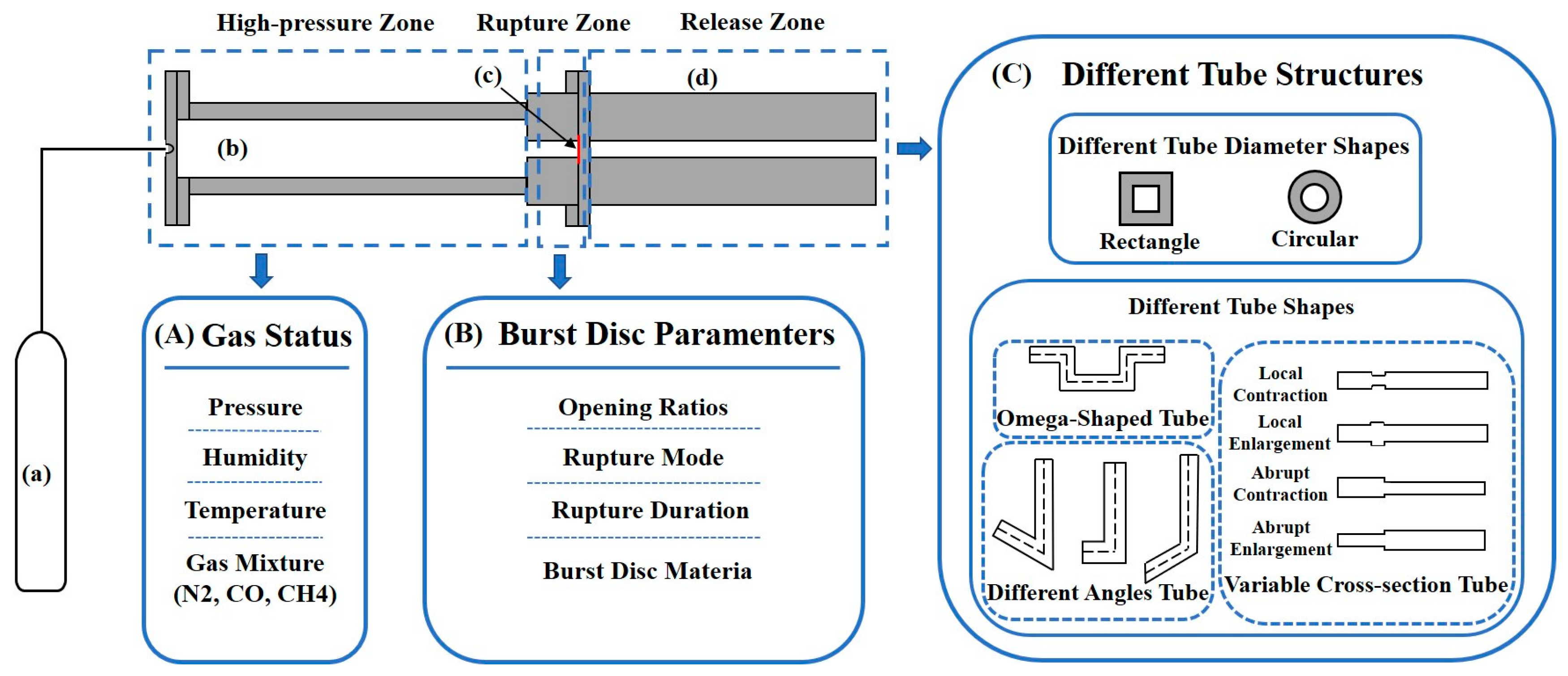
To facilitate the analysis of the influencing factors of hydrogen autoignition, the entire experimental apparatus for high-pressure hydrogen leakage and spontaneous combustion is divided into three sections: high-pressure zone, rupture zone, and release zone, as illustrated in Figure 2. The high-pressure zone, serving as the storage section for high-pressure hydrogen, is influenced by factors such as hydrogen release pressure, temperature, humidity, and the mixture of different hydrogen gas components; the rupture zone is mainly related to the burst disc, encompassing the rupture pressure, material, crack shape, opening rate and rupture time; the release zone mainly pertains to the downstream tube structure (tube diameter, tube length, tube cross-sectional shape, geometry), obstacles in the tube, and other conditions. Most experimental studies indicate that the autoignition of high-pressure leaked hydrogen results from the combined effects of various factors, with each factor directly influencing the shock wave and thereby affecting the autoignition of hydrogen.
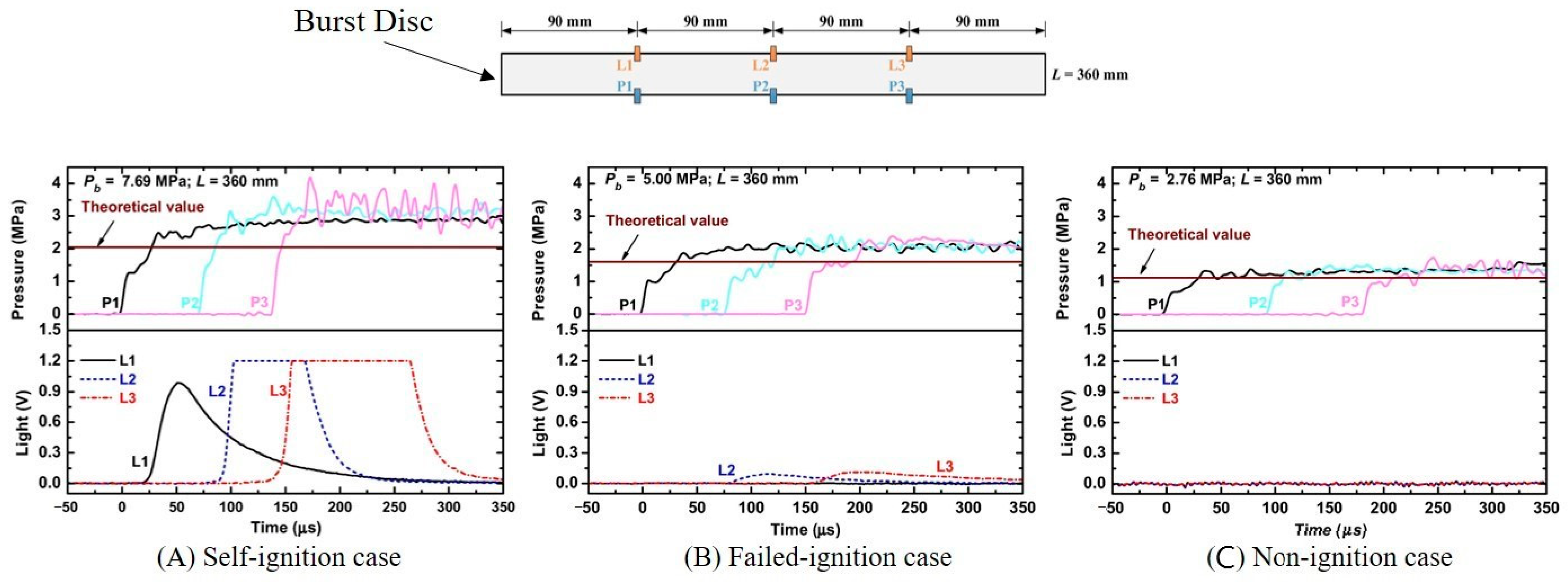
Three classic experimental events can be identified according to the onset and progression of ignition: autoignition, failed-ignition, and non-ignition. Autoignition, also known as spontaneous ignition or successful ignition, refers to ignition occurring not only inside a tube but successfully developing into a jet flame in an open space. As illustrated in Figure 3A, three light sensors detect a strong light signal, with the light intensity progressively increasing along the tube, and a jet flame can be observed outside the tube. Failed-ignition is a phenomenon where a self-igniting flame is observed early in the experiment, but the flame goes out within a short period of time, i.e., the ignition fails to evolve into a sustained flame. As depicted in Figure 3B, the second and third light sensors detect the autoignition flame; however, the light signal is relatively weak, and a jet flame is not emitted from the tube. Non-ignition is defined as the absence of ignition detected during the entire process of high-pressure hydrogen discharge, as shown in Figure 3C, where none of the three photosensors detected a light signal.

3.1. Study on the Effect of Gas State on Autoignition

The state of the gas is related to the rupture pressure of the burst disc and the nature of the gas itself. The rupture pressure determines the release pressure of high-pressure hydrogen gas. The higher the release pressure, the stronger the intensity of the shock wave generated ahead of the hydrogen jet. This results in greater heating and mixing of the hydrogen as it travels downstream, increasing its susceptibility to spontaneous combustion. The properties of gas consist mainly of its initial temperature and initial mixing concentration with other gases. As the initial temperature of hydrogen rises, the lower flammability limit (LFL) of hydrogen decreases [60], and the minimum ignition energy (MIE) of the hydrogen–air mixture also decreases [57,61], making it more susceptible to autoignition under shock wave action. Furthermore, the addition of impurity gases (CH4, N2, CO) can also significantly affect autoignition during the release of high-pressure hydrogen.
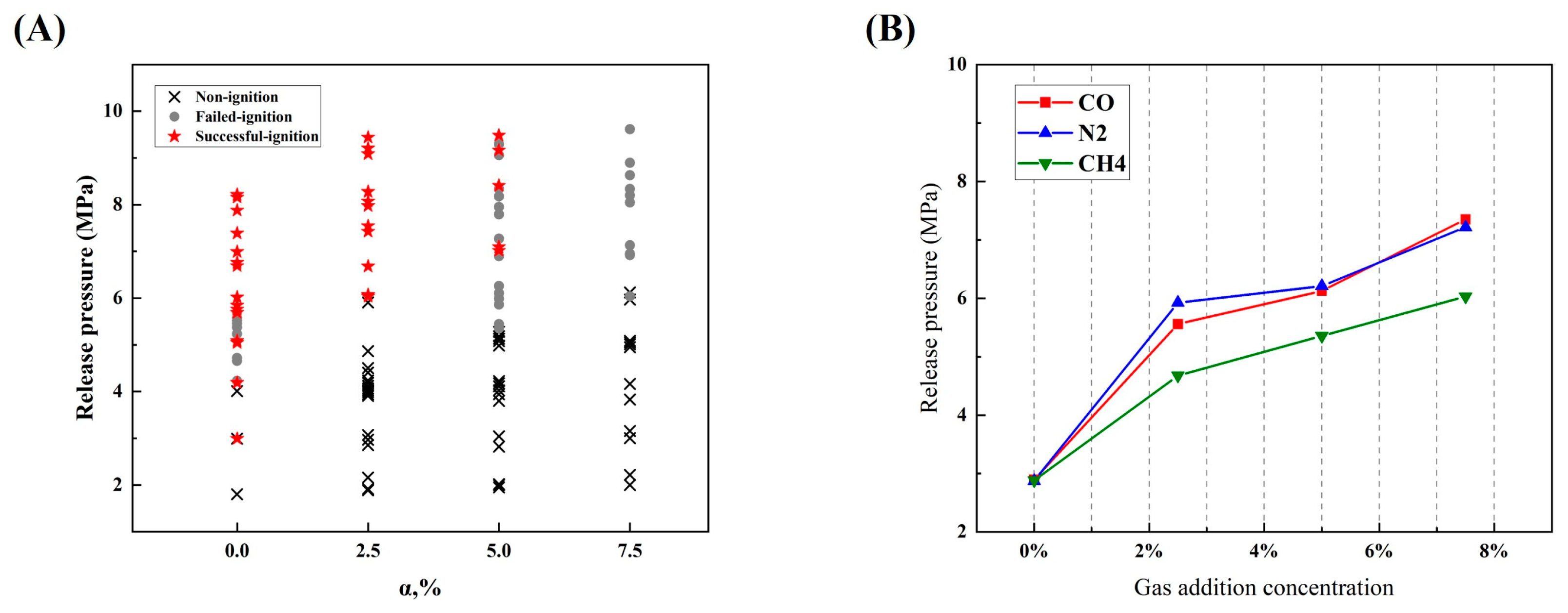
Taking high-pressure hydrogen doped with methane as an example, the addition of methane decreases the intensity of the shock wave inside the tube, which in turn lowers combustible mixture temperature. Moreover, the minimum ignition energy of a hydrogen–methane mixture is higher compared to that of pure hydrogen. Thus, increasing the amount of methane added could lower the likelihood of spontaneous combustion, but with the addition of methane, once a jet fire is generated in a closed space, a higher overpressure could be created, resulting in larger injuries, deaths, and property damage. Zeng et al. [55,62] investigated this by adding different ratios of methane to hydrogen, demonstrating that the minimum discharge pressure necessary for autoignition increases dramatically with the addition of methane, as illustrated in Figure 4A. It was also found that all ignitions first appeared near the tube wall and that there were two ignition modes, which is consistent with previous observations [63]. By adding N2 and CO to hydrogen [64,65], it was found that the impurity gases reduce the likelihood of spontaneous combustion in the same order as they reduce the intensity of the shock wave. The impact of N2 is similar to that of CO and greater compared to the effect of adding the equivalent volume of methane, as shown in Figure 4B. It is further proven that the reduction in spontaneous ignition of binary mixtures is mainly achieved by reducing the intensity of the shock wave, and the lowering effect is enhanced by increasing the molecular weight of the fuel.

3.2. Study on the Effect of Burst Disc on Autoignition

Shock tube experiments are currently the most effective method for studying the spontaneous ignition of high-pressure leaked hydrogen. In the 1970s, Tanaka et al. [66] conducted experiments involving the sudden release of hydrogen into the atmosphere using a tube equipped with a diaphragm. They found that hydrogen could undergo autoignition under those conditions, and since then, burst discs have gradually been used in experiments on high-pressure hydrogen leakage autoignition. The burst disc, positioned between the high-pressure hydrogen reservoir and the extension tube, divides the experimental setup into an upstream high-pressure zone and a downstream atmospheric pressure zone. This configuration controls the abrupt discharge of high-pressure hydrogen at a specified pressure, which is crucial for generating leading shock waves downstream. In addition, the rupture process, opening size, and rupture time of the burst disc can impact the shock wave and thus the high-pressure hydrogen leakage autoignition.
For each storage pressure, there exists a critical orifice size [67], as shown in Figure 5A. If the burst disc opening size is smaller than this critical size, ignition will be prevented during the release of hydrogen. This implies that autoignition will not occur if the rupture rate is below a specific threshold [15]. In a previous study on burst disc opening ratio and opening size, Lee et al. [31] found a significant tendency towards spontaneous combustion of hydrogen as the area of the open hole increased, as depicted in Figure 5B. When the opening area ratio is 1, the minimum release pressure required to cause autoignition is 85 bar. This finding aligns with Kim’s experimental results [37], which show a marginal increase in the minimum rupture pressure required to trigger spontaneous combustion as the opening area ratio decreases, a trend that persists until the ratio reaches 1/2. When the opening area ratio is 1/4, no ignition is triggered even if the rupture pressure is nearly 100 bar. This is because the smaller opening area generates a weaker shock wave, resulting in insufficient heating of the air [45,68]. Furthermore, experiments on hydrogen autoignition at lower opening ratios (1/8) revealed that the minimum release pressure required to trigger autoignition increases exponentially with the decrease in opening area [69], as shown in Figure 5B. This is because the opening size determines the speed of expansion or cooling of the spread layer at the jet front. The smaller the aperture, the faster the pressure drops at the leading edge of the jet, consequently requiring a higher release pressure for ignition. However, reducing the opening area enhances the blending effect. While the likelihood of autoignition decreases at the same discharge pressure, the likelihood of autoignition increases when the leading shock wave has the same impact velocity.
By comparing the experimental results of Lee [31], Gong [43], and Cha [69] et al., as shown in Figure 5B, it is found that the results are consistent for opening ratios less than or equal to 1/2. However, for opening ratios greater than 1/2, the threshold release pressure of Gong et al. [43] is lower. It is known that the threshold release pressure that can lead to spontaneous combustion is lower in rectangular tubes than in round tubes, which is inconsistent with the comparison results in Figure 5B. Combined with the parameters of the previous experimental setups for burst disc opening ratio studies listed in Table 3, the authors speculate that this is due to the different burst disc materials.
For the phenomena analyzed above, Duan et al. [73] found that the experimentally determined minimum release pressures leading to spontaneous combustion are significantly different even when the downstream tubes are of the same diameter and length under various hydrogen release conditions. They speculated that a possible reason for this difference might be the varying burst disc materials. These materials lead to different rupture processes, affecting the shock wave’s intensity and mixing effects.
The rupture process of the burst disc is critical to the autoignition of a high-pressure hydrogen leakage [15], and it encompasses both the rupture time and the rupture mode. The bursting time of the burst disc plays a crucial role in hydrogen autoignition as it alters the initial compression of the diffusion layer [67]. On this basis, Golovastov et al. [28] established a link between the rupture duration of the burst disc and the ignition delay. Their sequence of experiments demonstrated that an increased rupture rate increases the likelihood of hydrogen spontaneous combustion under the same initial hydrogen pressure. A faster rupture rate leads to quicker jet velocity, faster shock wave formation, and a more rapid onset of ignition. Additionally, they discovered that the hydrogen autoignition delay is related to the diaphragm’s rupture rate, as shown in Figure 6A. As for rupture mode, numerical simulations have verified the sensitivity of spontaneous combustion phenomena to the rupture process. Specifically, the asymmetric opening of the burst disc influences spontaneous combustion [53]. This happens because irregular ruptures of the burst disc result in varying shock wave intensities, even under constant release pressures. Consequently, this leads to significant dispersion in the experimental data [74]. The dispersion also occurs in the threshold release pressures for spontaneous combustion under the same release tube length conditions [41], as shown in Figure 6B, which may originate from accidental rupture of the burst disc and variations in burst disc materials. The impact strength and impact flow rate could be managed by choosing the appropriate rupture disc material, suitable thickness, and indentation depth.

3.3. Study of the Effect of Tube Geometry on Autoignition

3.3.1. The Effect of Tube Length and Diameter on Autoignition
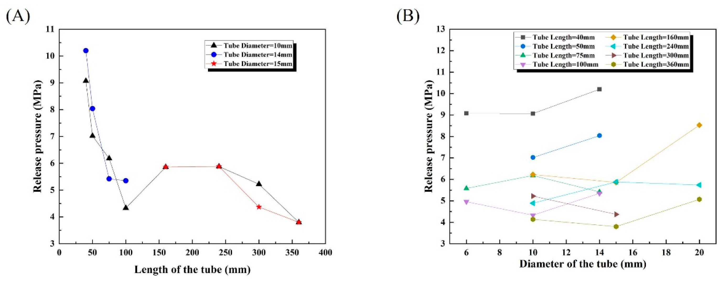
For straight tubes, the minimum discharge pressure required for autoignition depends on the length and diameter of the tube. As shown in Figure 7A, for the same release tube diameter, the threshold release pressure for autoignition decreases as the length of the release tube increases, thereby increasing the likelihood of spontaneous combustion. This is because a longer release tube provides an extended duration for the hydrogen and air to mix thoroughly.
The minimum release pressure for hydrogen autoignition decreases as the tube length increases [75]. However, the relationship between the threshold release pressure for autoignition and the tube length is not linear. For tubes with a diameter of 10 mm, the lowest release pressure for spontaneous hydrogen combustion occurs when the tube length ranges between 1.0 m and 1.2 m [76]. Asahara et al. [56] further investigated the influence of tube length on the autoignition of hydrogen and found that the shape and behavior of the jet after the propagating leading shock wave and the following shock wave remain unchanged for different lengths of tubes. When the tube is short, the autoignition flame does not fully develop and is thus extinguished due to the temperature and pressure reduction caused by the expanding wave at the tube’s outlet. Conversely, in a longer tube, the spontaneous combustion flame is fully developed. It can exit the tube, forming a stable flame unaffected by the temperature and pressure reduction at the outlet. Moreover, as hydrogen passes through a certain length of the tube, the resulting water vapor acts as a “lid”. This “lid” prevents further mixing of air and hydrogen when the flame has spread across the entire mixture area, thereby stopping additional flame production.
For tubes of different diameters, the minimum release pressure required for autoignition is influenced by the intensity of the shock wave and the mixing of hydrogen with air. In rectangular visualization channels, the required minimum discharge pressure for ignition decreases as the channel width decreases [77]. This happens because reducing the channel width induces significant perturbations to the flow and shock waves in the boundary layer, thereby affecting the compression, mixing, and ignition of the hydrogen–air mixtures. Moreover, it was found that an increase in the thickness of the boundary layer narrows the shock wave transmission channel, potentially causing the formation of reflected shock waves and extended waves [49]. Consequently, the shock wave’s velocity decreases due to its reduced intensity. When the interface between the hydrogen jet and the air reaches the boundary layer, its speed increases due to the reduction in cross-sectional area, similar to a nozzle structure. Duan et al. [73] conducted experiments on tubes of identical length but varying diameters and found that the minimum release pressure for autoignition of a 20 mm diameter tube is larger than that of the other two diameters (10 mm and 15 mm). On one hand, they suggest that the shock wave’s intensity inside the tube typically decreases with larger tube diameters, hindering autoignition. On the other hand, increasing the tube diameter provides more space for the blending of hydrogen and air, assuming the shock wave intensity is sufficient for ignition. Summarizing the experimental data for tubes of identical length, it was observed that the minimum release pressure required for autoignition was less affected by the diameter of the tube, as shown in Figure 7B, further confirming the effect law that autoignition is strongly correlated with the tube length and weakly correlated with the tube diameter [58].
By analyzing and summarizing the previous data, it was found that the release tube diameters primarily range around 5 mm, 10 mm, 15 mm, and 20 mm during the experiment. All data have been compiled into Table 4, categorizing similar tube diameters as the first feature and increasing tube lengths as the second feature. Overall, with shorter tube lengths, the diameter has a significant impact on the minimum release pressure required for spontaneous combustion, resulting in a wider range of experimentally measured minimum release pressures for autoignition. As the tube length increases, the minimum release pressure becomes more consistent, leading to a narrower range of experimental data. As shown in Figure 8A, the minimum release pressure that could cause autoignition is concentrated between 2 and 20 MPa when the release tube has a diameter of 5 mm and a length between 0 and 200 mm; In Figure 8B, with a release tube diameter of 10 mm and a length ranging from 0 to 500 mm, the minimum release pressure for autoignition concentrates within the range of 3–13 MPa. Figure 8C shows that the minimum release pressure causing autoignition is concentrated at 3–10 MPa when the release tube diameter is approximately 15 mm and the length ranges from 0 to 400 mm. In Figure 8D, the minimum release pressure for autoignition is concentrated at 4–8 MPa with release tube diameters of 10 mm, 25 mm, and 32 mm and lengths ranging from 0 to 400 mm.
Figure 7. The influence of tube diameter on the minimum release pressure necessary for autoignition for the same tube length [32,41,73,78,79]. (A) The variation of the minimum rupture pressure required for autoignition with tube length for different tube diameters; (B) the variation of the minimum rupture pressure required for autoignition with tube diameter for different tube lengths.
Fire 07 00268 g007
Figure 8. The impact of tube length on the lowest rupture pressure necessary for autoignition for the same tube diameter. (A) The impact of tube length on the lowest rupture pressure necessary for autoignition when the tube diameter is 5 mm (except where specially marked) [39,74,75,78,79,80]; (B) the impact of tube length on the lowest rupture pressure necessary for autoignition at a tube diameter of 10 mm [41,48,49,73,74,75,76,79,80,81,82]; (C) the impact of tube length on the lowest rupture pressure necessary for autoignition when the tube diameter is 15 mm (except where specially marked) [32,35,43,47,73,79,83]; (D) the impact of tube length on the lowest rupture pressure necessary for autoignition when the tube diameters are 20, 25, and 32 mm, respectively [73,82].
Fire 07 00268 g008
Table 4. Influence of tube diameter and tube length on the lowest rupture pressure required for autoignition.
Tube Diameter
(mm)
Tube
Length
(mm)
Rupture Pressure (MPa)AuthorTube Diameter
(mm)
Tube
Length
(mm)
Rupture Pressure (MPa)Author
S-IgnitionF-IgnitionN-IgnitionS-IgnitionF-IgnitionN-Ignition
43020.03 19.88Grune [78]51858.7711.71 Mogi [74]
424.99 4.82 7.0511.11
582.45 1.69 30019.17 13.33Mogi [75]
772.66 2.33 40011.55
1204.23 4.06 50012.85
50 12.30Golub [39]610 15.65Rudy [79]
20 20.52Mogi [75] 25 16.19
18.95Mogi [74] 409.38 9.36
5018.74 15.20Mogi [75] 9.08 9.11
659.60 9.60Golub [39] 8.67
7.70 5010.79 9.19
70 7.51Mogi [74] 8.79 8.76
8515.5611.7811.50Mogi [75] 7.73 8.32
15.6421.6913.11Mogi [74] 8.14
20.67 7.75
18.48 7.45
14.79 756.37 6.25
958.60 8.60Golub [39] 6.20 5.85
8.00 7.20 5.78 5.63
100 7.46Mogi [74] 5.58 5.33
13511.73 8.38Mogi [75] 5.28
1405.20 4.60Golub [39] 5.21
18511.8518.4610.79Mogi [75] 4.99
13.26 1007.11 4.79
10.55 6.94 5.28
9.38 5.68 5.95
4.00 3.80Golub [39] 4.96
16.5621.5110.07Mogi [74]6.66608.00 7.01Zhang [80]
14.5219.326.58
105 20.24Mogi [74]1025 17.21Rudy [79]
10 18.19 4010.73 10.51
15.51Rudy [79] 9.07 10.46
1040 10.39Rudy [79]103005.50 4.50Kitabayashi [76]
10.33 7.00 5.97Wang [48]
10.16 5.97 4.97
9.59 3503.91 4.10Kaneko [41]
9.52 3.70
9.42 3604.14 4.16Duan [73]
9.34 2.84
507.02 9.05 4009.3611.7311.14Mogi [75]
7.47 8.36
7.32 4.80Kitabayashi [76]
6.82 500 10.6611.67Mogi [75]
756.18 8.01 10.84
7.05 8.66
6.82 6406.25 5.04Zhang [80]
6.03 7005.93 5.84Wang [48]
80 9.11Kaneko [41] 6.04 4.86Xu [49]
13.31 10.66Mogi [75] 9775.00 4.00Jiang [81]
1004.33 8.51Rudy [79] 12004.80 Kitabayashi [76]
4.37 4.99 4.05Wang [48]
1355.68 6.21Kaneko [41] 1700 4.80Kitabayashi [76]
5.59 4.99 4.13Wang [48]
1606.23 9.94Duan [73] 4.14 2.99
7.09 22006.94 5.91
5.27 5.92 4.97
18510.7811.079.07Mogi [75] 30009.04 8.84
1905.22 5.96Kaneko [41] 7.91 7.92
190 5.82 7.06
2404.89 3.91Duan [73] 3200 4.80Kitabayashi [76]
2454.84 4.43Kaneko [41]1410 15.84Rudy [79]
3009.26 10.96Mogi [75] 25 16.34
7.47 4010.20 13.28
5.22 4.96Kaneko [41] 11.19
4.77 11.12
4.67 10.37
4.34 10.12
3.70 9.82
14508.04 9.50Rudy [79]152405.885.42 Duan [32]
8.36 5.20
8.23 4.71
7.99 4.40
755.42 5.30 4.05
5.60 4.13 4.08Duan [73]
5.75 3.81
6.17 3005.00 4.78Wang [35]
6.99 4.8941.024.28Gong [83]
1005.35 4.88 4.37 3.30Gong [43]
3.33 4.75 5.885.384.12Duan [32]
4.73 4.984.983.90
4.58 4.654.743.02
4.11 3.83
4.06 3603.80 4.14Duan [73]
3.49 3.87
3.41 3.09
3.21 9.50 9.00Zhu [47]
1580 8.907.89Duan [32] 7004.76 4.53Wang [35]
1208.847.807.84 6.02 4.97Xu [49]
7.10 12003.83 3.09Wang [35]
1606.85 6.09 17003.91 2.79
5.93 5.31 22004.92 4.06
5.86 30005.15 4.30
5.47 201608.53 6.89Duan [73]
5.55 6.14Duan [73] 2405.74 5.38
5.35 3605.07 5.14
2406.996.653.77Duan [32] 4.72
S-ignition: Successful ignition, which is defined as ignition that not only occurs in a test tube during an experiment but also evolves successfully into a jet flame in an open space; F-ignition: Failed-ignition, i.e., autoignition is noted early on and subsequently extinguished within a brief period of time, which means the ignition fails to evolve into a sustainable flame; N-ignition: Non-ignition, which means no ignition is detectable during the entire process of pressurized hydrogen discharge.

3.3.2. The Effect of Tube Structure on Autoignition

For non-straight tubes, the minimum rupture pressure required for autoignition is influenced by the tube geometry and obstructions within the tube [82]. This is because the geometry of the jet path or the objects in the path significantly affects the propagation and development of the shock wave, especially at relatively low release pressures, which may enhance sustained combustion [51]. The cross-sectional shape, geometric configuration, tube angles, and internal obstacles within the release tube have an important effect on autoignition.
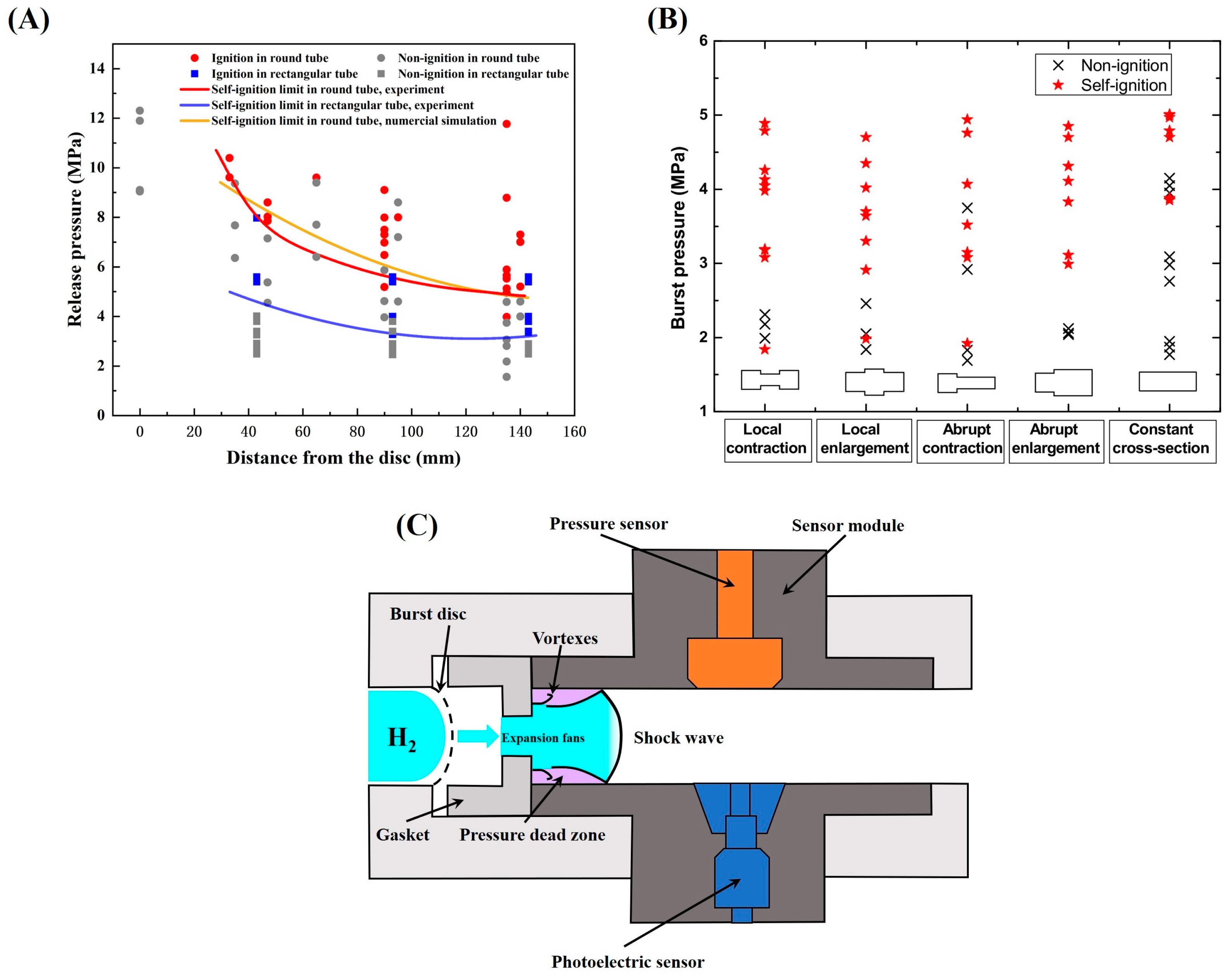
For circular and rectangular tubes with the same cross-sectional area, the critical release pressure leading to spontaneous combustion is lower for rectangular tubes than for circular tubes [39,46,70], as shown in Figure 9A. This difference is attributed to the formation of distinct flow boundary layers in different cross-sections due to the shock waves generated during the outflow of the pulsed jet. In addition, the tube cross-section affects the nature of spontaneous combustion. For instance, in rectangular tubes, initial autoignition typically occurs at the center of the sidewall [84]. This is caused by the mixing of hydrogen and air facilitated by jets generated from the reflection of the bow shock wave, resulting in adiabatic shock compression and subsequent temperature rise. This increase in temperature induces secondary autoignition at the corners of the tubes. Unlike rectangular tubes, when autoignition occurs, a distinct ring of autoignition appears near the sidewalls in cylindrical tubes.
In contrast to changing the cross-sectional shape of the release tube, Zhang et al. [80] modified the inlet shape by adding baffles between the burst disc and the release tube, as shown in Figure 9C. It was found that the shape of the inlet significantly influences the properties of the shock wave, given the same inlet area and release pressure. Specifically, circular inlets generate the highest shock wave intensity and average velocity, followed by the square inlets, with the triangular inlet producing the lowest. Compared to circular air inlets, non-circular ones reduce the likelihood of autoignition.
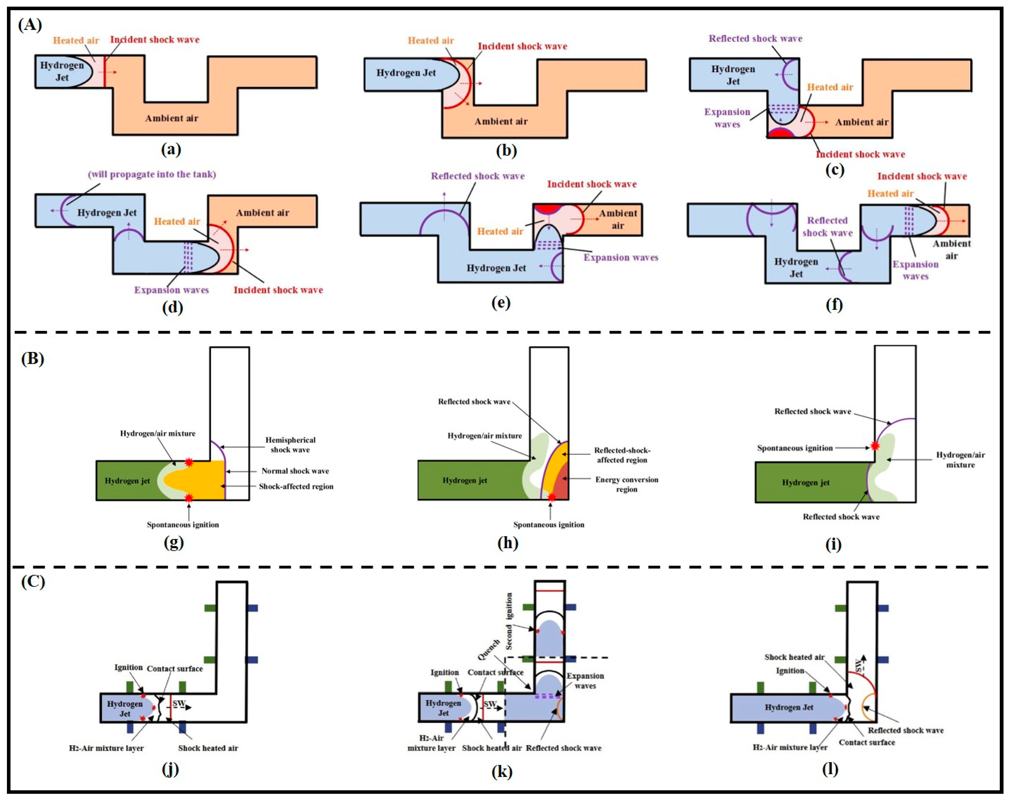
The changes in the tube cross-sections unavoidably lead to the generation of multidimensional shock waves and the evolution of sophisticated flows within the tube. This results in the minimum release pressure for successful autoignition of a variable cross-section tube being considerably lower than that of an equal cross-section tube, with the initial ignition location nearer to the burst disc, as illustrated in Figure 9B. The variable cross-section tube significantly enhances autoignition [85]. In the case of a locally constricted tube, the sudden narrowing of the tube cross-section impedes hydrogen jet transmission, decelerates shock wave velocity, and amplifies their reflection and coupling effects [30]. Currently, the mechanism of spontaneous ignition in locally constricted tubes involves two scenarios: (1) at high release pressures, reflected shock waves trigger autoignition near the tube wall; (2) at low release pressures, interactions between shock waves initiate autoignition at the tube’s center.
Gong et al. [29,83,86] studied the influence of downstream geometry on the autoignition of hydrogen using an Ω-shaped tube, and found that the pressure within the Ω-tube is significantly higher than in the straight tube as a consequence of the interaction of the shock wave and the reflected shock wave, as shown in Figure 10A.
When comparing tubes under identical release pressures, flames in an Ω-shaped tube are detected sooner and closer to the burst disc than in other tube shapes. Consequently, the geometry of the downstream tube has a significant effect on the autoignition of hydrogen, and the use of an Ω-shaped tube greatly enhances the chance of autoignition in pressurized hydrogen. To further explore the influence of downstream tube geometry on shock ignition and shock wave generation during the sudden expansion of high-pressure hydrogen, five more tubes with various angles (60°, 90°, 120°, 150°, and 180°) were designed. The study revealed that shock ignition tends to manifest in tubes with smaller angles and that the threshold pressure necessary for shock ignition decreases with smaller angles of the tube.
For L-shaped right-angle tubes [87,88] and circular-arc tubes [89], the effect on autoignition differs. With right-angle tubes, the transmission of the leading shock wave inside the tube becomes more complex, owing to the presence of the reflected shock wave, resulting in different autoignition mechanisms, as shown in Figure 10B,C. The position of the right angle in the L-tube dramatically affects hydrogen autoignition; the closer the right angle is to the burst disc, the lower the threshold pressure required for autoignition. Regarding the circular arc tube, the reflected shock wave propagating downstream enhances the intensity of the leading shock wave, but the velocity of the leading shock wave decreases more rapidly in a curved tube than in a straight tube. It was found that as the curved tube approaches the burst disc, it is less likely to undergo autoignition, and that the circular arc tube has an inhibitory effect on spontaneous combustion as compared with a straight tube.
Furthermore, obstacles within the tube can also have an effect on the autoignition of hydrogen. The position of the obstacle significantly alters the interaction of the shock wave with the incident contact surface, from which three different ignition mechanisms are derived [90]: (1) ignition occurs when the contact surface passes through high-temperature regions generated by the reflected excitation wave, which are produced by the interaction of the leading excitation wave with the obstacle, as illustrated in Figure 11A; (2) ignition occurs when the incoming contact surface interacts with reflected shock waves from two obstacles along the central line, as depicted in Figure 11B; (3) ignition occurs as the shock wave reflected by the obstacle is reflected by other walls in the vicinity of the area of mixing of hydrogen gas and shock-heated air, as depicted in Figure 11C. If the obstacle is situated in an asymmetric location, the reflected shock wave from the upper obstacle is reflected to the lower wall and generates a high-temperature zone. Meanwhile, the leading shock wave reaches the lower obstacle, and the reflected shock wave from the lower obstacle generates another high-temperature zone. Subsequently, as the contact surface arrives at this zone, spontaneous combustion occurs, as shown in Figure 11D. It has been found that tubes with symmetrical obstacles experience a much higher intensity of reflected shock waves compared to tubes with asymmetrical obstacles. These reflected shock waves further compress the air and enhance the mixing of hydrogen with air, potentially leading to autoignition [38,91]. For tubes with asymmetric obstacles, secondary ignition is more likely to occur.
The effect of an obstacle on autoignition is influenced by its comprehensive effect on the generation of hydrogen–air mixtures and on temperature elevation. Li et al. [92,93,94,95] experimentally showed that the transient weakening of shock wave intensity created by obstacles is not favorable for spontaneous combustion; however, sophisticated fluid flow produced by obstacles can foster the onset of autoignition. The position, spacing, shape, and obstruction rate of the obstacles within the tube can also significantly influence the shock wave propagation and the ignition mechanism of hydrogen autoignition [96]. When the obstruction is positioned closer to the burst disc, resulting in less spacing, the obstruction rate increases, leading to a higher intensity of the reflected shock wave and, consequently, a greater likelihood of autoignition. The propagation tendencies of reflected shock waves from obstacles with the same obstruction ratio but different shapes are similar. However, the obstacle shape affects the occurrence of autoignition (autoignition onset time: triangle < semicircle < rectangle) and the enhancement of flame intensity (rectangle > semicircle > triangle). Similarly, reflected shock waves from obstacles of the same shape but varying obstruction ratios also exhibit a comparable transmission tendency. Nevertheless, the higher the obstacle’s obstruction ratio, the less time it takes for autoignition to take place, the larger the intensity of the flame, and the larger the high-speed zone produced after it passes through the obstacle.

4. Combustion Characteristics of High-Pressure Hydrogen Gas Leakage Autoignition Flame

4.1. Study of the Evolution Characteristics of the Autoignition Flame in the Tube
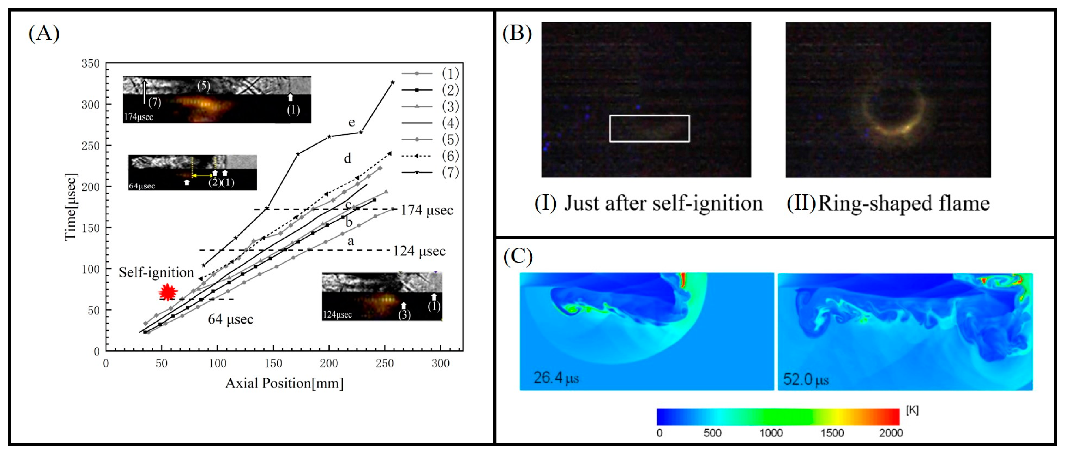
Most scholars [30,87,97] define the criterion for spontaneous combustion in tube simulations to be an OH mole fraction greater than 1 × 10⁻³. The transient multidimensional shock wave triggered by the rupture of the burst disc and the subsequent interactions during the evolution of the flow intensifies the mixing of the air and the expanding hydrogen, which leads to the spontaneous combustion of the hydrogen inside the tube [98]. If spontaneous combustion flames within a tube are to further evolve into jet flames, this process will be influenced by the concentration of the hydrogen–air mixture and the state of premixed flame development within the tube [99,100]. Kim et al. [37] found that autoignition in a circular tube initially occurs in the boundary layer of the mixing zone, and demonstrated the structure of the flow field and flame in conjunction with the measured locations of the shock wave, the mixing zone, the flame, and the theoretical contact surfaces as shown in Figure 12A. The self-igniting flames convect over the airflow behind the shock wave, spreading along the sidewalls and eventually converging on the tube center [101]. If the hydrogen jet is sufficient to penetrate the leading shock wave along the axis of symmetry, a vortex ring in the tip region is formed. After boundary layer ignition, the turbulent blending effect of the vortex ring induces secondary ignition at the axis and mixes with the boundary layer flame, subsequently forming a complete flame across the entire cross-section [98,102]. The flame condition in rectangular tubes is distinct from circular tubes, characterized by multiple ignition kernels at the center or corners of the tube walls, unlike the singular or dual ignition kernels found in the boundary layer or axis of circular tubes [52]. This phenomenon was similarly observed in the experiments conducted by Li et al. [95] and Asahara et al. [84]. It is important to note that the initial autoignition mechanism within the tube is independent of the cross-sectional shape, and develops from ignition kernels within the boundary layer to a flame that travels downstream through the tube. However, the location of ignition is influenced by the tube’s cross-sectional shape [103]. The boundary layer on the inner wall of the cylindrical tube is marked by uniformity. After ignition, a ring-shaped flame develops along the boundary layer. In rectangular tubes, due to the interaction of the temperature boundary layer and velocity boundary layer on the horizontal and vertical walls, the temperature at the corners is lower while secondary flow occurs [104,105], and the spontaneous ignition time at the corners is longer and the flame propagation speed is faster.
Regarding the transition of flames from the interior to the exterior of a tube, Lee et al. [100] observed that when only the flame near the tube wall was present at the tube outlet, it weakened and extinguished after leaving the tube. Successful spontaneous ignition outside the tube only occurs when the flame spans the entire tube cross-section, suggesting that an intact flame traveling through the entire tube contributes to the development of the diffuse flame outside the tube [106]. Figure 12A shows a typical image of the spontaneous combustion process in a downstream tube recorded through a viewing window fixed to the port of the damper section [50]. The ignition kernel was initially observed near the lower wall of the test tube, leading to the formation of an annular or cylindrical flame, as illustrated in Figure 12B. This flame shape is consistent with findings from earlier research on cylindrical tubes [101,107]. It is obvious from the shock tube that the hydrogen jet on the central axis of the tube and the shock-heated air move at an identical velocity, so the hydrogen hardly mixes with the air heated close to the central axis. This leads to the formation of a cylindrical flame within the boundary layer near the tube wall.
Besides the formation of a complete flame across the entire cross-section of the tube, a large amount of shock wave-heated air and the fully developed partially premixed flame are key factors enabling the hydrogen autoignition flame to overcome the strong under-expansion flow and disperse out of the tube [108]. Kitabayashi et al. [76] elucidated the propagation characteristics of spontaneous combustion flames beyond the tube using high-speed camera technology combined with numerical simulation methods. They found that the Mach disk structure appeared in front of the jet due to conditions such as under-expansion and flow divergence. As the autoignition flame spreads beyond the tube, combustion occurs downstream of the Mach disk, as illustrated in Figure 12C. They hypothesize that this is mainly due to the fact that the burning mixture gas, after experiencing a brief quench due to low-temperature expansion, enters the high-temperature region downstream of the Mach disk structure and is reignited [109]. Xu et al. [110,111] found that when the leading shock wave travels downstream of the constricted section, a distinct Mach disk gradually develops within the constricted low-expansion jet, while a ring-shaped supersonic flow arises along the tube wall. In addition to the repetitive reflection of shock waves along the tube walls and axes, these complicated flow evolutions produce high levels of turbulence that greatly distort the contact area and enhance mixing. Although the ignition kernels form in the contact zone where the hydrogen concentration is low, the partially premixed flames develop rapidly due to the rapid intensive mixing by turbulence and are highly deformed by the turbulence and overlap each other.
Figure 12. (A) Location of autoignition onset, shock wave, mixture zone, and flame propagation at 9.0 MPa release pressure [37]; (1) shock wave, (2) hybrid front, (3) flame front, (4) theoretical contact surface, (5) hybrid center, (6) flame center (peak signal position of the light sensor), (7) hybrid tail (disappearing position of the light sensor). (a) Non-compressed air; (b) compressed air; (c) mixing and flaming zone at the core; (d) boundary layer mixing and flame zone; (e) hydrogen expansion zone. (B) Images of autoignition process within the experimental segment [50]. Release stress: 8.8 MPa, impact speed: 1600 m/s. (C) Numerical simulation of the temperature profile of hydrogen emitted from a tube with a diameter of 10 mm and a length of 10 mm at a storage tank pressure of 40.0 MPa and inlet pressures and temperatures of 21.3 MPa and 250 kPa, respectively [109].
Fire 07 00268 g012

4.2. Study of the Propagation Characteristics of Jet Flame outside the Tube

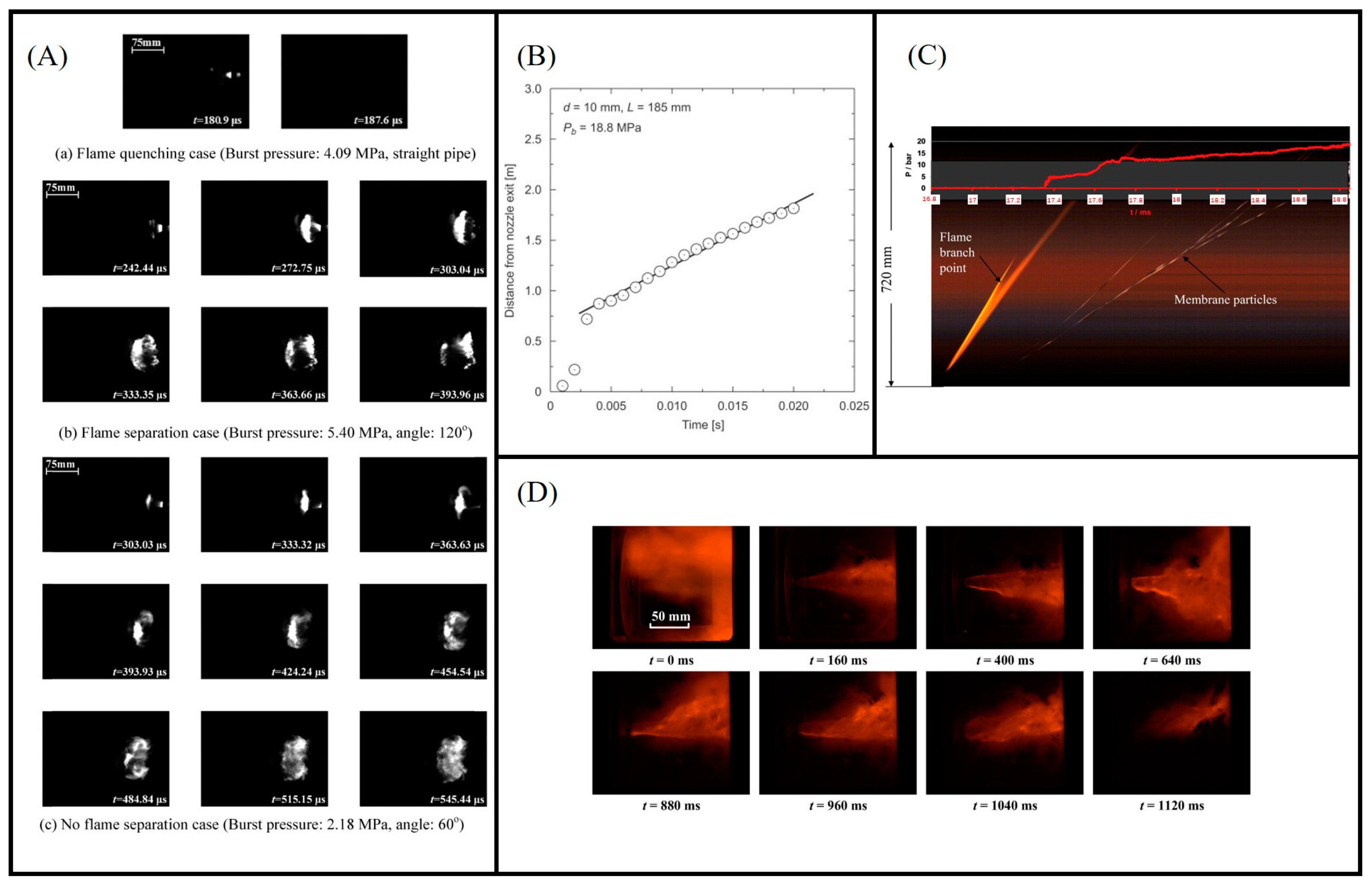
By investigating the flame propagation characteristics, Duan et al. [85] showed that the evolution of flames beyond the tube primarily depends on the release pressure and exterior conditions, rather than the geometry of the tube. Different release pressures lead to distinct flame structures. Three cases can be distinguished for flames in the discharge tube [83]: flame extinction, flame separation, and no flame separation. Flame extinction refers to the flame generated inside the tube being instantly extinguished upon exiting the discharge tube, as illustrated in Figure 13A. Flame separation refers to the initial formation of a small flame near the tube outlet, which rapidly grows into a spherical structure. As the fireball continues to spread, the area of the flame increases. Due to the vortex generated near the pipe outlet, the fireball splits into two parts [112]. The front part of the flame propagates forward and extinguishes as the hydrogen burns out, while the rear part of the flame remains at the tube outlet and gradually grows. It was found that flame separation results from a recirculation zone formed by vortex activity and expansion near the tube’s orifice [86,112]. As depicted in Figure 13B, the initial sharp increase in the displacement velocity of the flame front is succeeded by a gradual increase, and eventually stabilizing at a constant value [54,75]. For the variation of the peak flame displacement velocity, Mogi et al. [74] discovered that although the velocity increases significantly near the nozzle, the flame propagation distance increases almost linearly from 0.7 m, indicating that the flame spreads at a constant velocity, as illustrated in Figure 13B. The initial velocity of the flame front is relatively low due to the jet’s expansion, which decelerates convection in the diffusion layer, consequently reducing the flame propagation speed [54]. Subsequently, due to the swift momentum transfer of the hydrogen jet in an open space, a substantial volume of hydrogen–air mixture forms ahead of the flame. This results in the rapid advancement of the flame, causing a sharp increase in velocity. In later stages, the flame velocity decreases and oscillates with an average value of 400 m/s as a reduced rate of hydrogen momentum transfer occurs [85]. As shown in Figure 13C, No flame separation refers to the overall downward propagation of the flame without flame separation.
When a hydrogen jet ignites successfully, it forms a spherical flame near the nozzle exit, which then expands and diffuses axially. Finally, the diffused jet flame remains visible and sustained until hydrogen is exhausted [74]. As shown in Figure 13C, the flame fans out along the flow distance in the direction of the nozzle exhaust as it progresses [109]. It is observed that the flame branches in two directions in the long tube: one direction couples with the leading shock wave, and the other coincides with the location of the primary contact surface. If the length of the extension tube exceeds the position of the flame branching point, the jet flame at the nozzle outlet becomes unobservable. Duan et al. [32] further investigated the morphology of the jet flame and found that its shape is affected by the dimensionless Froude number, as shown in Figure 13D.
Previous studies on the influence of nozzle dimensions and injection pressure on jet diffusion flame dimensions (length and width) and flame radiation found that flame length mainly depends on fuel type and flow conditions (release intensity and fracture geometry characteristics, etc.) [113,114,115]. Proust et al. [116] conducted a large experiment on jet flames during the blowdown of high-pressure hydrogen reservoirs. The investigation, with experimental pressure raised to 930 bar, revealed a significant departure from the ideal gas law in the pattern of hydrogen density variation with pressure and temperature, particularly when the pressure exceeded 200 bar. Regarding the geometric shape of the flame, L/D (the ratio of flame length to maximum flame width) remains constant. It should be noted that, due to their simple structure and symmetry, circular tubes or orifices are predominantly used in current research for conducting experiments on shock tube models for better observation of the phenomena, numerical simulation, and unification of the principles. However, in practical engineering, cracks in gas tubes or hydrogen storage tanks are not always circular. They can also include irregular shapes such as tiny slits. Many scholars conducted detailed studies on slit venting [114,117,118,119] and found that the phenomena and principles are very different from those of circular orifice venting.
A study on the impact of internal structural changes in the tube on flame shape revealed that variable-section and equal-section tubes show no notable differences in flame propagation characteristics (flame shape, flame front velocity, etc.) [85], but there is a significant difference in the effect of tube cross-section changes on hydrogen release. The presence of an obstacle inside the tube causes a shrinking structure in the tube, thus leading to a faster flow rate. Furthermore, obstructions inside the tube induce turbulence, increasing the mixing of the hydrogen/air mixture with shock wave-heated air, thereby enhancing combustion inside the tube. However, this turbulence has less effect on the jet flame outside the tube. Kim et al. [120] studied the influence of obstacles outside the tube on flame intensity, revealing that the wall surface alters the flow structure of the hydrogen jet without influencing ignition. In shorter tubes, creating a robust flame within the tube is challenging, and even recirculation mixing at the edges of the tube wall does not effectively promote the reaction between hot air and hydrogen.
When the tube length is sufficient to generate a robust flame inside the tube, the wall plays a role in stabilizing the flame. The obstacle plate not only strengthens thin flames after spontaneous combustion before jet impingement but also promotes spontaneous combustion in the stagnation zone. However, under both circumstances, the flame is unable to withstand the intense secondary divergence from the edge of the obstacle plate [121]. In practical engineering, different obstacles may be encountered. Wang et al. [122] conducted a comprehensive analysis of the flame morphology, temperature, and hazardous area of jet flames for different barrier structures. It was found that, in comparison to vertical obstacles, obstacles with intricate structures induce the secondary deflection of the flame, diminishing its propagation in the vertical direction. However, these structures also cause the flame to backflow, making it hotter near the nozzle and more likely to explode. In addition, the variation in obstacle shapes affects the initial flame detection position and the length of the flame [97].
From the perspective of safety, when jet flames and deflagration occur due to leakage outside the hydrogen container or tube, the damage caused by the explosion overpressure, shock waves, and thermal radiation to humans and facilities is also inestimable. To understand the hazards of jet flames, Imamura et al. [113] explored the morphological development and thermal radiation properties of hydrogen jet flames through a series of experiments. They established empirical formulas to predict the flame length and width based on release pressure and tube diameter. In addition, in the scenario of a substantial release of hydrogen, there is a potential for hazardous shock waves, high explosive shocks, and other dangers [123]. It was found that hydrogen concentration [124] and ignition location [125] have a significant effect on the explosion. To avoid bringing serious losses, Mironov et al. [126] proposed measures to mitigate the hazard of the explosion of unstable high-pressure hydrogen jets released into obstructed space.

5. Conclusions

This paper provides a detailed overview of hydrogen autoignition mechanisms based on diffusion ignition theory, factors influencing autoignition, and flame combustion characteristics. The following conclusions have been drawn:
  • Various factors within the high-pressure and rupture zones influence shock wave generation, while factors within the release zone affect shock wave propagation. Differences in gas properties, burst disc rupture conditions, tube geometric structure, and obstacles lead to variations in shock wave growth patterns. These factors combine to determine the occurrence of spontaneous combustion, and as long as one of these factors is above or below the threshold, spontaneous combustion cannot occur. For instance, even with a burst pressure of 100 bar, a sufficient shock wave intensity to ignite hydrogen cannot be generated when the aperture area is 1/4.
  • When the tube length is shorter, the diameter has a significant impact on the minimum release pressure required for autoignition, resulting in a broader range of experimentally measured minimum release pressures. However, as the tube length increases, the minimum release pressure required for autoignition gradually becomes more concentrated, leading to a narrower range of experimental data.
  • The ignition of the “diffusion ignition” mechanism occurs within the most reactive hydrogen–air mixture, with hydrogen concentrations ranging from 19% to 36% by volume. After the kernel of autoignition is generated, it gradually develops into a premixed flame under the interaction of a large number of shock waves. Once a complete flame spanning the entire cross-section of the tube is formed internally, the flame transitions to an external jet. The development of an external flame differs from autoignition, primarily influenced by release pressure and external conditions rather than tube geometric structure. The intrinsic factor affecting flame development is the vortex, and therefore the study of the vortex can help understand the propagation of a jet flame outside a tube.

6. Outlook

Based on a summary of previous studies, it has been found that there are still some issues in the current research on high-pressure hydrogen leakage and autoignition. Several future prospects for this field have been proposed, suggesting directions for further expanding and refining research on safety issues related to high-pressure hydrogen leakage:
  • Currently, research on the spontaneous combustion of high-pressure hydrogen leaks often relies on shock tube models, with tube cross-sections typically being rectangular or circular. However, in practical engineering, the rupture shapes of high-pressure tanks or pipelines are often irregular, and the presence of obstacles in the leak environment complicates shock wave propagation. To enhance the effective application of research outcomes in hydrogen safety engineering, further studies should be conducted based on existing research foundations, focusing on various release scenarios. For instance, conditions involving metal mesh inside tubes and slit conditions should be considered.
  • Current research predominantly focuses on the impact of individual factors on high-pressure hydrogen leakage and autoignition, with limited depth in studying the characteristics underlying the coupled effects of multiple factors. Future research should investigate the growth patterns of shock waves under different influencing factors to comprehensively understand the autoignition characteristics under coupled multi-factor conditions.
  • The current study only focuses on shock waves’ macroscopic effects on the boundary layer. There is a lack of in-depth exploration into how shock wave intensity affects the distribution of hydrogen concentration gradients and temperature rise rates within the boundary layer. The mechanisms by which shock waves enhance hydrogen–air diffusion mixing and boundary layer heating are also inadequately understood. Future research should delve deeper into how shock waves influence gas properties (such as temperature and mixing levels) within the boundary layer and investigate the relationship between gas characteristics and the generation of autoignition ignition kernels.

Author Contributions

Conceptualization, G.C.; methodology, D.W., H.L. (Huan Liu), H.L. (Hongwei Li) and X.X.; software, Y.L. and D.W.; validation, Y.L. and D.W.; formal analysis, G.C.; investigation, D.W., H.L. (Hongwei Li), H.L. (Huan Liu) and X.X.; resources, G.C. and J.L.; data curation, D.W., H.L. (Hongwei Li), H.L. (Huan Liu) and X.X.; writing—original draft preparation, Y.L.; writing—review and editing, G.C.; visualization, Y.L. and D.W.; supervision, J.L.; project administration, G.C.; funding acquisition, G.C. All authors have read and agreed to the published version of the manuscript.

Funding

This work is supported by Shandong Provincial Natural Science Foundation of China (ZR2023ME088), National Natural Science Foundation of China (Grant No. 51804329).

Data Availability Statement

The data presented in this study are available on request from the corresponding author. The data are not publicly available due to privacy and confidentiality concerns.

Conflicts of Interest

Author Hongwei Li was employed by the company PetroChina Qinghai Oilfield Company Gas Production Plant. The remaining authors declare that the research was conducted in the absence of any commercial or financial relationships that could be construed as a potential conflict of interest.

References

  1. Noussan, M.; Raimondi, P.P.; Scita, R.; Hafner, M. The Role of Green and Blue Hydrogen in the Energy Transition—A Technological and Geopolitical Perspective. Sustainability 2020, 13, 298. [Google Scholar] [CrossRef]
  2. Penner, S.S. Steps toward the hydrogen economy. Energy 2006, 31, 33–43. [Google Scholar] [CrossRef]
  3. Dincer, I. Green methods for hydrogen production. Int. J. Hydrogen Energy 2012, 37, 1954–1971. [Google Scholar] [CrossRef]
  4. Sarkar, A.; Banerjee, R. Net energy analysis of hydrogen storage options. Int. J. Hydrogen Energy 2005, 30, 867–877. [Google Scholar] [CrossRef]
  5. Elberry, A.M.; Thakur, J.; Santasalo-Aarnio, A.; Larmi, M. Large-scale compressed hydrogen storage as part of renewable electricity storage systems. Int. J. Hydrogen Energy 2021, 46, 15671–15690. [Google Scholar] [CrossRef]
  6. Yang, F.; Wang, T.; Deng, X.; Dang, J.; Huang, Z.; Hu, S.; Li, Y.; Ouyang, M. Review on hydrogen safety issues: Incident statistics, hydrogen diffusion, and detonation process. Int. J. Hydrogen Energy 2021, 46, 31467–31488. [Google Scholar] [CrossRef]
  7. Ono, R.; Nifuku, M.; Fujiwara, S.; Horiguchi, S.; Oda, T. Minimum ignition energy of hydrogen–air mixture: Effects of humidity and spark duration. J. Electrost. 2007, 65, 87–93. [Google Scholar] [CrossRef]
  8. Crowl, D.A.; Jo, Y.-D. The hazards and risks of hydrogen. J. Loss Prev. Process Ind. 2007, 20, 158–164. [Google Scholar] [CrossRef]
  9. Green, M.A. Hydrogen safety issues compared to safety issues with methane and propane. AIP Conf. Proc. 2006, 823, 319–326. [Google Scholar]
  10. Duan, Q.; Xiao, H.; Gao, W.; Shen, X.; Wang, Q.; Sun, J. Experimental investigation on shock waves generated by pressurized gas release through a tube. J. Loss Prev. Process Ind. 2015, 36, 39–44. [Google Scholar] [CrossRef]
  11. Najjar, Y.S.H. Hydrogen safety: The road toward green technology. Int. J. Hydrogen Energy 2013, 38, 10716–10728. [Google Scholar] [CrossRef]
  12. Kotchourko, A.; Baraldi, D.; Bénard, P.; Jordan, T.; Keßler, A.; LaChance, J.; Steen, M.; Tchouvelev, A.V.; Wen, J.X. Stare of the Art and Research Priorities in Hydrogen Safety; Publications Office of the European Union: Luxembourg, 2014. [Google Scholar]
  13. Meda, U.S.; Bhat, N.; Pandey, A.; Subramanya, K.N.; Raj, M.A.L.A. Challenges associated with hydrogen storage systems due to the hydrogen embrittlement of high strength steels. Int. J. Hydrogen Energy 2023, 48, 17894–17913. [Google Scholar] [CrossRef]
  14. Astbury, G.; Hawksworth, S. Spontaneous ignition of hydrogen leaks: A review of postulated mechanisms. Int. J. Hydrogen Energy 2007, 32, 2178–2185. [Google Scholar] [CrossRef]
  15. Xu, B.P.; Wen, J.X.; Dembele, S.; Tam, V.H.Y.; Hawksworth, S.J. The effect of pressure boundary rupture rate on spontaneous ignition of pressurized hydrogen release. J. Loss Prev. Process Ind. 2009, 22, 279–287. [Google Scholar] [CrossRef]
  16. Wolanski, P.; Wojcicki, S. Investigation into the Mechanism of the Diffusion Ignition of a Combustible Gas Flowing into an Oxidizing Atmosphere. In Proceedings of the 14th International Symposium on Combustion, University Park, PA, USA, 20–25 August 1972. [Google Scholar]
  17. National Aeronautics and Space Administration Report. Safety Standard for Hydrogen and Hydrogen Systems; Report NSS 1740.16; Office of Safety and Mission Assurance: Washington, DC, USA, 1997; p. A-16.
  18. Michels, A.; de Graaff, W.; Wolkers, G.J. Thermodynamic properties of hydrogen and deuterium at temperatures between −175°C and 150°C and at densities up to 840 amagat. Physica 1959, 25, 1097–1124. [Google Scholar] [CrossRef]
  19. Camp, P.R. Charge, morphology, and pH of natural snow. J. Geophys. Res. 1976, 81, 1589–1592. [Google Scholar] [CrossRef]
  20. Molkov, V. Hydrogen safety research: State-of-the-art. In Proceedings of the 5th International Seminar on Fire and Explosion Hazards, Edinburgh, UK, 23–27 April 2007; pp. 28–43. [Google Scholar]
  21. Cain, T.M. Autoignition of hydrogen at high pressure. Combust. Flame 1997, 111, 124–132. [Google Scholar] [CrossRef]
  22. Powell, F. Ignition of gases and vapours by hot surfaces and particles—A review. In Proceedings of the 9th International Symposium on the Prevention of Occupational Accidents and Diseases in the Chemical Industry, Lucerne, Switzerland, 5–7 June 1984. [Google Scholar]
  23. Cho, P.; Law, C.K. Catalytic ignition of fuel/oxygen/nitrogen mixtures over platinum. Combust. Flame 1986, 66, 159–170. [Google Scholar] [CrossRef]
  24. Powell, F. Ignition of flammable gases and vapours by friction between footwear and flooring materials. J. Hazard. Mater. 1977, 2, 309–319. [Google Scholar] [CrossRef]
  25. Pan, L.; Fisher, S.A.; Jayanti, S.; Hewitt, G.F. Measurement and prediction of temperature rise following sudden compression in a high-pressure pipeline. Process Saf. Environ. Prot. 1995, 73, 18–20. [Google Scholar]
  26. Duan, Q.; Xiao, H.; Gong, L.; Li, P.; Zeng, Q.; Gao, W.; Sun, J. Experimental study of shock wave propagation and its influence on the spontaneous ignition during high-pressure hydrogen release through a tube. Int. J. Hydrogen Energy 2019, 44, 22598–22607. [Google Scholar] [CrossRef]
  27. Golovastov, S.V.; Bocharnikov, V.M.; Samoilova, A.A. Experimental investigation of influence of methane additions on spontaneous self-ignition of pulsed jet of hydrogen. Int. J. Hydrogen Energy 2016, 41, 13322–13328. [Google Scholar] [CrossRef]
  28. Golovastov, S.; Bocharnikov, V. The influence of diaphragm rupture rate on spontaneous self-ignition of pressurized hydrogen: Experimental investigation. Int. J. Hydrogen Energy 2012, 37, 10956–10962. [Google Scholar] [CrossRef]
  29. Gong, L.; Zheng, X.; Yang, S.; Yao, Y.; Xie, Y.; Mo, T.; Zhang, Y. Numerical study on the shock evolution and the spontaneous ignition of high-pressure hydrogen during its sudden release into the tubes with different angles. Fuel 2023, 331, 125940. [Google Scholar] [CrossRef]
  30. Jin, K.; Yang, S.; Gong, L.; Mo, T.; Gao, Y.; Zhang, Y. Mechanism of spontaneous ignition of high-pressure hydrogen during its release through a tube with local contraction: A numerical study. Int. J. Hydrogen Energy 2022, 47, 6421–6436. [Google Scholar] [CrossRef]
  31. Lee, H.J.; Lee, S.Y.; Park, J.H.; Jeung, I.-S. Effects of opening conditions on the self-ignition of high pressurized hydrogen released through a tube. In Proceedings of the 25th International Colloquium on the Dynamics of Explosions and Reactive Systems, Leeds, UK, 2–7 August 2015. [Google Scholar]
  32. Duan, Q.; Xiao, H.; Gao, W.; Gong, L.; Wang, Q.; Sun, J. Experimental study on spontaneous ignition and flame propagation of high-pressure hydrogen release via a tube into air. Fuel 2016, 181, 811–819. [Google Scholar] [CrossRef]
  33. Baev, V.K.; Shumskii, V.V.; Yaroslavtsev, M.I. Self-ignition of a fuel gas escaping into an oxidizing medium. Combust. Explos. Shock Waves 1983, 19, 600–605. [Google Scholar] [CrossRef]
  34. Baev, V.K.; Buzukov, A.A.; Shumskii, V.V. Conditions of self-ignition upon pulsed high-pressure injection of combustible gases into a bounded space. Combust. Explos. Shock Waves 2000, 36, 3–10. [Google Scholar] [CrossRef]
  35. Wang, Z.; Pan, X.; Jiang, Y.; Wang, Q.; Yan, W.; Xiao, J.; Jordan, T.; Jiang, J. Experiment study on the pressure and flame characteristics induced by high-pressure hydrogen spontaneous ignition. Int. J. Hydrogen Energy 2020, 45, 18042–18056. [Google Scholar] [CrossRef]
  36. Yamada, E.; Watanabe, S.; Hayashi, A.K.; Tsuboi, N. Numerical analysis on auto-ignition of a high pressure hydrogen jet spouting from a tube. Proc. Combust. Inst. 2009, 32, 2363–2369. [Google Scholar] [CrossRef]
  37. Kim, Y.R.; Lee, H.J.; Kim, S.; Jeung, I.-S. A flow visualization study on self-ignition of high pressure hydrogen gas released into a tube. Proc. Combust. Inst. 2013, 34, 2057–2064. [Google Scholar] [CrossRef]
  38. Duan, Q.; Tang, J.; Jin, K.; Zeng, Q.; Wu, Y.; Zhang, S.; Wang, Q.; Sun, J. Experimental investigation of shock wave propagation, spontaneous ignition, and flame development of high-pressure hydrogen release through tubes with different obstacles arrangements. Int. J. Hydrogen Energy 2022, 47, 38075–38086. [Google Scholar] [CrossRef]
  39. Golub, V.V.; Baklanov, D.I.; Golovastov, S.V.; Ivanov, M.F.; Laskin, I.N.; Saveliev, A.S.; Semin, N.V.; Volodin, V.V. Mechanisms of high-pressure hydrogen gas self-ignition in tubes. J. Loss Prev. Process Ind. 2008, 21, 185–198. [Google Scholar] [CrossRef]
  40. Bazhenova, T.V.; Bragin, M.V.; Golub, V.V.; Ivanov, M.F. Self-ignition of a fuel gas upon pulsed efflux into an oxidative medium. Tech. Phys. Lett. 2006, 32, 269–271. [Google Scholar] [CrossRef]
  41. Kaneko, W.; Ishii, K. Effects of diaphragm rupturing conditions on self-ignition of high-pressure hydrogen. Int. J. Hydrogen Energy 2016, 41, 10969–10975. [Google Scholar] [CrossRef]
  42. Gong, L.; Jin, K.; Zheng, X.; Han, Y.; Yao, Y.; Duan, Q.; Zhang, Y.; Sun, J. Effect of Al-made burst disk on the shock wave and the spontaneous ignition of high-pressure hydrogen during its sudden discharge. J. Energy Storage 2023, 72, 108371. [Google Scholar] [CrossRef]
  43. Gong, L.; Duan, Q.; Liu, J.; Li, M.; Jin, K.; Sun, J. Effect of burst disk parameters on the release of high-pressure hydrogen. Fuel 2019, 235, 485–494. [Google Scholar] [CrossRef]
  44. Rudy, W.; Teodorczyk, A.; Wen, J. Self-ignition of hydrogen–nitrogen mixtures during high-pressure release into air. Int. J. Hydrogen Energy 2017, 42, 7340–7352. [Google Scholar] [CrossRef]
  45. Golub, V.V.; Baklanov, D.I.; Bazhenova, T.V.; Bragin, M.V.; Golovastov, S.V.; Ivanov, M.F.; Volodin, V.V. Shock-induced ignition of hydrogen gas during accidental or technical opening of high-pressure tanks. J. Loss Prev. Process Ind. 2007, 20, 439–446. [Google Scholar] [CrossRef]
  46. Golub, V.V.; Baklanov, D.I.; Bazhenova, T.V.; Golovastov, S.V.; Ivanov, M.F.; Laskin, I.N.; Semin, N.V.; Volodin, V.V. Experimental and numerical investigation of hydrogen gas auto-ignition. Int. J. Hydrogen Energy 2009, 34, 5946–5953. [Google Scholar] [CrossRef]
  47. Zhu, M.; Jin, K.; Duan, Q.; Zeng, Q.; Sun, J. Numerical simulation on the spontaneous ignition of high-pressure hydrogen release through a tube at different burst pressures. Int. J. Hydrogen Energy 2022, 47, 10431–10440. [Google Scholar] [CrossRef]
  48. Wang, Z.; Pan, X.; Wang, Q.; Jiang, Y.; Xu, X.; Yan, W.; Jiang, J. Experimental study on spontaneous ignition and flame propagation of high-pressure hydrogen release through tubes. Int. J. Hydrogen Energy 2019, 44, 22584–22597. [Google Scholar] [CrossRef]
  49. Xu, X.; Jiang, J.; Jiang, Y.; Wang, Z.; Wang, Q.; Yan, W.; Pan, X. Spontaneous ignition of high-pressure hydrogen and boundary layer characteristics in tubes. Int. J. Hydrogen Energy 2020, 45, 20515–20524. [Google Scholar] [CrossRef]
  50. Kaneko, W.; Ishii, K. An experimental study on the mechanism of self-ignition of high-pressure hydrogen. Int. J. Hydrogen Energy 2017, 42, 7374–7379. [Google Scholar] [CrossRef]
  51. Dryer, F.L.; Chaos, M.; Zhao, Z.; Stein, J.N.; Alpert, J.Y.; Homer, C.J. Spontaneous Ignition of Pressurized Releases of Hydrogen and Natural Gas into Air. Combust. Sci. Technol. 2007, 179, 663–694. [Google Scholar] [CrossRef]
  52. Yamashita, K.; Saburi, T.; Wada, Y.; Asahara, M.; Mogi, T.; Hayashi, A.K. Visualization of spontaneous ignition under controlled burst pressure. Int. J. Hydrogen Energy 2017, 42, 7755–7760. [Google Scholar] [CrossRef]
  53. Bragin, M.V.; Makarov, D.V.; Molkov, V.V. Pressure limit of hydrogen spontaneous ignition in a T-shaped channel. Int. J. Hydrogen Energy 2013, 38, 8039–8052. [Google Scholar] [CrossRef]
  54. Radulescu, M.I.; Law, C.K. The transient start of supersonic jets. J. Fluid Mech. 2007, 578, 331–369. [Google Scholar] [CrossRef]
  55. Zeng, Q.; Duan, Q.; Sun, D.; Li, P.; Zhu, M.; Wang, Q.; Sun, J. Experimental study of methane addition effect on shock wave propagation, self-ignition and flame development during high-pressure hydrogen sudden discharge from a tube. Fuel 2020, 277, 118217. [Google Scholar] [CrossRef]
  56. Asahara, M.; Saburi, T.; Ando, T.; Takahashi, Y.; Miyasaka, T.; Kubota, S. Self-ignited flame behavior of high-pressure hydrogen release by rupture disk through a long tube. Int. J. Hydrogen Energy 2021, 46, 13484–13500. [Google Scholar] [CrossRef]
  57. Cirrone, D.; Makarov, D.; Proust, C.; Molkov, V. Minimum ignition energy of hydrogen-air mixtures at ambient and cryogenic temperatures. Int. J. Hydrogen Energy 2023, 48, 16530–16544. [Google Scholar] [CrossRef]
  58. Zhou, S.; Luo, Z.; Wang, T.; He, M.; Li, R.; Su, B. Research progress on the self-ignition of high-pressure hydrogen discharge: A review. Int. J. Hydrogen Energy 2022, 47, 9460–9476. [Google Scholar] [CrossRef]
  59. Sun, L.; Jia, C.; Miao, Y. Visualization of hydrogen leak for electro-hydrogen coupled system based on Background Oriented Schlieren. Process Saf. Environ. Prot. 2023, 175, 437–446. [Google Scholar] [CrossRef]
  60. Zhang, K.; Luo, T.; Li, Y.; Zhang, T.; Li, X.; Zhang, Z.; Shang, S.; Zhou, Y.; Zhang, C.; Chen, X.; et al. Effect of ignition, initial pressure and temperature on the lower flammability limit of hydrogen/air mixture. Int. J. Hydrogen Energy 2022, 47, 15107–15119. [Google Scholar] [CrossRef]
  61. Ghosh, A.; Munoz-Munoz, N.M.; Lacoste, D.A. Minimum ignition energy of hydrogen-air and methane-air mixtures at temperatures as low as 200 K. Int. J. Hydrogen Energy 2022, 47, 30653–30659. [Google Scholar] [CrossRef]
  62. Zeng, Q.; Duan, Q.; Li, P.; Zhu, H.; Sun, D.; Sun, J. An experimental study of the effect of 2.5% methane addition on self-ignition and flame propagation during high-pressure hydrogen release through a tube. Int. J. Hydrogen Energy 2020, 45, 3381–3390. [Google Scholar] [CrossRef]
  63. Ivanov, M.F.; Kiverin, A.D.; Smygalina, A.E.; Golub, V.V.; Golovastov, S.V. Mechanism of self-ignition of pressurized hydrogen flowing into the channel through rupturing diaphragm. Int. J. Hydrogen Energy 2017, 42, 11902–11910. [Google Scholar] [CrossRef]
  64. Zeng, Q.; Jin, K.; Duan, Q.; Zhu, M.; Gong, L.; Wang, Q.; Sun, J. Effects of CO addition on shock wave propagation, self-ignition, and flame development of high-pressure hydrogen release into air. Int. J. Hydrogen Energy 2022, 47, 14714–14724. [Google Scholar] [CrossRef]
  65. Zeng, Q.; Duan, Q.; Jin, K.; Zhu, M.; Sun, J. Effects of nitrogen addition on the shock-induced ignition of high-pressure hydrogen release through a rectangular tube of 400 mm in length. Fuel 2022, 308, 122016. [Google Scholar] [CrossRef]
  66. Tanaka, K.; Urano, Y.; Iwasaka, M.; Hashiguchi, Y. The ignition of a compressed hydrogen by the discharge from a rupture disc. J. High Press. Gas Saf. Inst. Jpn. 1978, 15, 355–358. [Google Scholar]
  67. Maxwell, B.M.; Radulescu, M.I. Ignition limits of rapidly expanding diffusion layers: Application to unsteady hydrogen jets. Combust. Flame 2011, 158, 1946–1959. [Google Scholar] [CrossRef]
  68. Pan, X.; Lu, L.; Zhang, T.; Jiang, Y.; Li, Y.; Wang, Z.; Hua, M.; Jiang, J. Effect of the leak port area and tube length on suppression of spontaneous ignition of high-pressure hydrogen. J. Energy Storage 2023, 74, 109396. [Google Scholar] [CrossRef]
  69. Cha, S.-W.; Roh, T.-S.; Lee, H.J. Effect of opening area on the suppression of self-ignition of high-pressure hydrogen gas leaking in the air by an extension tube. Int. J. Hydrogen Energy 2021, 46, 5904–5915. [Google Scholar] [CrossRef]
  70. Golovastov, S.V.; Baklanov, D.I.; Volodin, V.V.; Golub, V.V.; Ivanov, K.V. An experimental study of the diffusion-controlled self-ignition of hydrogen in a channel. Russ. J. Phys. Chem. B 2009, 3, 348–355. [Google Scholar] [CrossRef]
  71. Xu, B.P.; El Hima, L.; Wen, J.X.; Tam, V.H.Y. Numerical study of spontaneous ignition of pressurized hydrogen release into air. Int. J. Hydrog. Energy 2009, 34, 5954–5960. [Google Scholar] [CrossRef]
  72. Liu, Y.F.; Tsuboi, N.; Sato, H.; Higashino, F.; Hayashi, A.K.; Gakuin, A. Direct numerical simulation on hydrogen fuel jetting from high pressure tank. In Proceedings of the 20th International Colloquium on the Dynamics of Explosion and Reactive Systems, Montreal, Canada, 31 July–5 August 2005. [Google Scholar]
  73. Duan, Q.; Xiao, H.; Gong, L.; Jin, K.; Gao, W.; Chai, H.; Sun, J. Experimental study on spontaneous ignition and subsequent flame development caused by high-pressure hydrogen release: Coupled effects of tube dimensions and burst pressure. Fire Saf. J. 2018, 97, 44–53. [Google Scholar] [CrossRef]
  74. Mogi, T.; Kim, D.; Shiina, H.; Horiguchi, S. Self-ignition and explosion during discharge of high-pressure hydrogen. J. Loss Prev. Process Ind. 2008, 21, 199–204. [Google Scholar] [CrossRef]
  75. Mogi, T.; Wada, Y.; Ogata, Y.; Hayashi, A.K. Self-ignition and flame propagation of high-pressure hydrogen jet during sudden discharge from a pipe. Int. J. Hydrogen Energy 2009, 34, 5810–5816. [Google Scholar] [CrossRef]
  76. Kitabayashi, N.; Wada, Y.; Mogi, T.; Saburi, T.; Hayashi, A.K. Experimental study on high pressure hydrogen jets coming out of tubes of 0.1–4.2 m in length. Int. J. Hydrogen Energy 2013, 38, 8100–8107. [Google Scholar] [CrossRef]
  77. Chen, J.R.; Tsai, H.Y.; Ku, C.W.; Lin, Y.C. Effect of Channel Width on the Shock and Ignition of High-Pressure Hydrogen Release. In Proceedings of the Seventh International Seminar Fire and Explosion Hazards, Providence, RI, USA, 5–10 May 2013; pp. 951–958. [Google Scholar]
  78. Grune, J.; Sempert, K.; Kuznetsov, M.; Jordan, T. Experimental study of ignited unsteady hydrogen releases from a high pressure reservoir. Int. J. Hydrogen Energy 2014, 39, 6176–6183. [Google Scholar] [CrossRef]
  79. Rudy, W.; Dabkowski, A.; Teodorczyk, A. Experimental and numerical study on spontaneous ignition of hydrogen and hydrogen-methane jets in air. Int. J. Hydrogen Energy 2014, 39, 20388–20395. [Google Scholar] [CrossRef]
  80. Zhang, T.; Jiang, Y.; Pan, X.; Wang, Z.; Wang, Q.; Li, Y.; Ta, L.; Hua, M.; Jiang, J. Effects of tubes with different inlet shapes on the shock wave and self-ignition induced by accidental release of pressurized hydrogen. Fuel 2022, 317, 123554. [Google Scholar] [CrossRef]
  81. Jiang, Y.; Pan, X.; Hua, M.; Wang, Z.; Zhang, T.; Wang, Q.; Li, Y.; Yu, A.; Jiang, J. Effect of flow directions in the T-shaped tubes on the shock wave and spontaneous ignition of pressurized hydrogen. Fuel 2023, 332, 126054. [Google Scholar] [CrossRef]
  82. Oleszczak, P.; Wolanski, P. Ignition during hydrogen release from high pressure into the atmosphere. Shock Waves 2010, 20, 539–550. [Google Scholar] [CrossRef]
  83. Gong, L.; Duan, Q.; Sun, Q.; Jin, K.; Sun, J. Effects of the geometry of downstream pipes with different angles on the shock ignition of high-pressure hydrogen during its sudden expansion. Int. J. Hydrogen Energy 2017, 42, 8382–8391. [Google Scholar] [CrossRef]
  84. Asahara, M.; Yokoyama, A.; Tsuboi, N.; Hayashi, A.K. Influence of tube cross-section geometry on high-pressure hydrogen-flow-induced self-ignition. Int. J. Hydrogen Energy 2023, 48, 7909–7926. [Google Scholar] [CrossRef]
  85. Duan, Q.; Xiao, H.; Gao, W.; Gong, L.; Sun, J. Experimental investigation of spontaneous ignition and flame propagation at pressurized hydrogen release through tubes with varying cross-section. J. Hazard. Mater. 2016, 320, 18–26. [Google Scholar] [CrossRef] [PubMed]
  86. Gong, L.; Duan, Q.; Jiang, L.; Jin, K.; Sun, J. Experimental study on flow characteristics and spontaneous ignition produced by pressurized hydrogen release through an Omega-shaped tube into atmosphere. Fuel 2016, 184, 770–779. [Google Scholar] [CrossRef]
  87. Gong, L.; Jin, K.; Yang, S.; Yang, Z.; Li, Z.; Gao, Y.; Zhang, Y. Numerical study on the mechanism of spontaneous ignition of high-pressure hydrogen in the L-shaped tube. Int. J. Hydrogen Energy 2020, 45, 32730–32742. [Google Scholar] [CrossRef]
  88. Pan, X.; Wang, Q.; Yan, W.; Jiang, Y.; Wang, Z.; Xu, X.; Hua, M.; Jiang, J. Experimental study on pressure dynamics and self-ignition of pressurized hydrogen flowing into the L-shaped tubes. Int. J. Hydrogen Energy 2020, 45, 5028–5038. [Google Scholar] [CrossRef]
  89. Li, Y.; Jiang, Y.; Pan, X.; Wang, Z.; Hua, M.; Wang, Q.; Ta, L.; Jiang, J. Effects of the arc-shaped corner on the shock wave and self-ignition induced by sudden release of pressurized hydrogen. Fuel 2021, 303, 121294. [Google Scholar] [CrossRef]
  90. Morii, Y.; Terashima, H.; Koshi, M.; Shimizu, T. Numerical study of the effect of obstacles on the spontaneous ignition of high-pressure hydrogen. J. Loss Prev. Process Ind. 2015, 34, 92–99. [Google Scholar] [CrossRef]
  91. Smygalina, A.E.; Kiverin, A.D. Self-ignition of hydrogen jet due to interaction with obstacle in the obstructed space. Int. J. Hydrogen Energy 2022, 47, 35877–35885. [Google Scholar] [CrossRef]
  92. Li, P.; Duan, Q.; Gong, L.; Jin, K.; Chen, J.; Sun, J. Effects of obstacles inside the tube on the shock wave propagation and spontaneous ignition of high-pressure hydrogen. Fuel 2019, 236, 1586–1594. [Google Scholar] [CrossRef]
  93. Li, P.; Duan, Q.; Jin, K.; Zeng, Q.; Sun, J. Experimental study on shock waves, spontaneous ignition, and flame propagation produced by pressurized hydrogen release through tubes with varying obstacle location. Fuel 2021, 290, 120093. [Google Scholar] [CrossRef]
  94. Li, P.; Zeng, Q.; Duan, Q.; Chen, X.; Sun, J. Effects of obstacles inside the tube on initial self-ignition of high-pressure hydrogen release through a tube. Fuel 2023, 339, 127354. [Google Scholar] [CrossRef]
  95. Li, P.; Zeng, Q.; Duan, Q.; Sun, J. Visualization of spontaneous ignition and flame behavior in tubes with and without obstacles during the high-pressure hydrogen release. Process Saf. Environ. Prot. 2021, 153, 354–362. [Google Scholar] [CrossRef]
  96. Li, X.; Teng, L.; Li, W.; Huang, X.; Li, J.; Luo, Y.; Jiang, L. Numerical simulation of the effect of multiple obstacles inside the tube on the spontaneous ignition of high-pressure hydrogen release. Int. J. Hydrogen Energy 2022, 47, 33135–33152. [Google Scholar] [CrossRef]
  97. Liu, Z.; Li, Z.; Luan, X.; Xu, W.; Zhao, S.; Zhang, B. Numerical study on the effects of the obstacle shapes on the spontaneous ignition of high-pressure hydrogen in a tube. Int. J. Hydrogen Energy 2024, 56, 1067–1078. [Google Scholar] [CrossRef]
  98. Lee, B.J.; Jeung, I.-S. Numerical study of spontaneous ignition of pressurized hydrogen released by the failure of a rupture disk into a tube. Int. J. Hydrogen Energy 2009, 34, 8763–8769. [Google Scholar] [CrossRef]
  99. Chang, X.; Bai, C.; Zhang, B.; Sun, B. The effect of ignition delay time on the explosion behavior in non-uniform hydrogen-air mixtures. Int. J. Hydrogen Energy 2022, 47, 9810–9818. [Google Scholar] [CrossRef]
  100. Lee, H.J.; Kim, Y.R.; Kim, S.-H.; Jeung, I.-S. Experimental investigation on the self-ignition of pressurized hydrogen released by the failure of a rupture disk through tubes. Proc. Combust. Inst. 2011, 33, 2351–2358. [Google Scholar] [CrossRef]
  101. Asahara, M.; Saburi, T.; Kubota, S.; Kubota, T.; Ando, T.; Miyasaka, T. Self-ignition and flame development of high-pressure hydrogen flow in a rectangular tube by simultaneous shadowgraph and direct photograph. In Proceedings of the Selected Papers from the 31st International Congress on High-Speed Imaging and Photonics, Osaka, Japan, 7–10 November 2016. [Google Scholar]
  102. Lee, H.J.; Park, J.H.; Kim, S.D.; Kim, S.; Jeung, I.-S. Numerical study on the spontaneous-ignition features of high-pressure hydrogen released through a tube with burst conditions. Proc. Combust. Inst. 2015, 35, 2173–2180. [Google Scholar] [CrossRef]
  103. Yokoyama, A.; Asahara, M.; Tsuboi, N.; Hayashi, A.K. Numerical study on three-dimensional flow effect of self-ignition induced by high pressure hydrogen jet in a rectangular tube. Sci. Technol. Energetic Mater. 2016, 77, 7–12. [Google Scholar]
  104. Gavrilakis, S. Numerical simulation of low-Reynolds-number turbulent flow through a straight square duct. J. Fluid Mech. 1992, 244, 101–129. [Google Scholar] [CrossRef]
  105. Huser, A.; Biringen, S. Direct numerical simulation of turbulent flow in a square duct. J. Fluid Mech. 1993, 257, 65–95. [Google Scholar] [CrossRef]
  106. Grune, J.; Kuznetsov, M.; Jordan, T. Spontaneous ignition process due to high-pressure hydrogen release in air. In Proceedings of the 4th International Conference of Hydrogen Safety, San Francisco, CA, USA, 12–14 September 2011. [Google Scholar]
  107. Kaneko, W.; Hayashi, K.; Ishii, K. Self-ignition of high-pressure hydrogen released by reproducible rupture of diaphragm. In Proceedings of the 25th International Colloquium on the Dynamics of Explosions and Reactive Systems, Leeds, UK, 2–7 August 2015. [Google Scholar]
  108. Wen, J.X.; Xu, B.P.; Tam, V.H.Y. Numerical study on spontaneous ignition of pressurized hydrogen release through a length of tube. Combust. Flame 2009, 156, 2173–2189. [Google Scholar] [CrossRef]
  109. Grune, J.; Sempert, K.; Kuznetsov, M.; Jordan, T. Experimental investigation of flame and pressure dynamics after spontaneous ignition in tube geometry. Int. J. Hydrogen Energy 2014, 39, 20396–20403. [Google Scholar] [CrossRef]
  110. Xu, B.P.; Wen, J.X. The effect of tube internal geometry on the propensity to spontaneous ignition in pressurized hydrogen release. Int. J. Hydrogen Energy 2014, 39, 20503–20508. [Google Scholar] [CrossRef]
  111. Xu, B.P.; Wen, J.X. Numerical study of spontaneous ignition in pressurized hydrogen release through a length of tube with local contraction. Int. J. Hydrogen Energy 2012, 37, 17571–17579. [Google Scholar] [CrossRef]
  112. Bragin, M.V.; Molkov, V.V. Physics of spontaneous ignition of high-pressure hydrogen release and transition to jet fire. Int. J. Hydrogen Energy 2011, 36, 2589–2596. [Google Scholar] [CrossRef]
  113. Imamura, T.; Hamada, S.; Mogi, T.; Wada, Y.; Horiguchi, S.; Miyake, A.; Ogawa, T. Experimental investigation on the thermal properties of hydrogen jet flame and hot currents in the downstream region. Int. J. Hydrogen Energy 2008, 33, 3426–3435. [Google Scholar] [CrossRef]
  114. Mogi, T.; Horiguchi, S. Experimental study on the hazards of high-pressure hydrogen jet diffusion flames. J. Loss Prev. Process Ind. 2009, 22, 45–51. [Google Scholar] [CrossRef]
  115. Gautam, T. Lift-off Heights and Visible Lengths of Vertical Turbulent Jet Diffusion Flames in Still Air. Combust. Sci. Technol. 2010, 41, 17–29. [Google Scholar]
  116. Proust, C.; Jamois, D.; Studer, E. High pressure hydrogen fires. Int. J. Hydrogen Energy 2011, 36, 2367–2373. [Google Scholar] [CrossRef]
  117. Ruggles, A.J.; Ekoto, I.W. Experimental investigation of nozzle aspect ratio effects on underexpanded hydrogen jet release characteristics. Int. J. Hydrogen Energy 2014, 39, 20331–20338. [Google Scholar] [CrossRef]
  118. Li, X.; Chen, M.; Wang, Y.; Hu, J.; Sun, Z.; Christopher, D.M.; Cheng, L. Measurements of concentration decays in underexpanded jets through rectangular slot nozzles. Int. J. Hydrogen Energy 2018, 43, 9884–9893. [Google Scholar] [CrossRef]
  119. Li, X.; Chen, Q.; Chen, M.; He, Q.; Christopher, D.M.; Cheng, X.; Chowdhury, B.R.; Hecht, E.S. Modeling of underexpanded hydrogen jets through square and rectangular slot nozzles. Int. J. Hydrogen Energy 2019, 44, 6353–6365. [Google Scholar] [CrossRef]
  120. Kim, S.; Lee, H.J.; Park, J.H.; Jeung, I.-S. Effects of a wall on the self-ignition patterns and flame propagation of high-pressure hydrogen release through a tube. Proc. Combust. Inst. 2013, 34, 2049–2056. [Google Scholar] [CrossRef]
  121. Xu, B.P.; Wen, J.X.; Tam, V.H.Y. The effect of an obstacle plate on the spontaneous ignition in pressurized hydrogen release: A numerical study. Int. J. Hydrogen Energy 2011, 36, 2637–2644. [Google Scholar] [CrossRef]
  122. Wang, J.; Luan, X.; Huo, J.; Jing, M.; Huffman, M.; Wang, Q.; Zhang, B. Numerical study on the effect of complex structural barrier walls on high-pressure hydrogen horizontal jet flames. Process Saf. Environ. Prot. 2023, 175, 632–643. [Google Scholar] [CrossRef]
  123. Gelfand, B.E.; Silnikov, M.V.; Medvedev, S.P.; Khomik, S.V. Thermo-Gas Dynamics of Hydrogen Combustion and Explosion; Springer: Berlin/Heidelberg, Germany, 2012. [Google Scholar]
  124. Luo, X.; Wang, C.; Rui, S.; Wan, Y.; Zhang, Z.; Li, Q. Effects of ignition location, obstacles, and vent location on the vented hydrogen-air deflagrations with low vent burst pressure in a 20-foot container. Fuel 2020, 280, 118677. [Google Scholar] [CrossRef]
  125. Wang, L.-Q.; Ma, H.-H.; Shen, Z.-W. Effects of vessel height and ignition position upon explosion dynamics of hydrogen-air mixtures in vessels with low asymmetry ratios. Fuel 2021, 289, 119926. [Google Scholar] [CrossRef]
  126. Mironov, V.N.; Penyazkov, O.G.; Ignatenko, D.G. Self-ignition and explosion of a 13-MPa pressurized unsteady hydrogen jet under atmospheric conditions. Int. J. Hydrogen Energy 2015, 40, 5749–5762. [Google Scholar] [CrossRef]
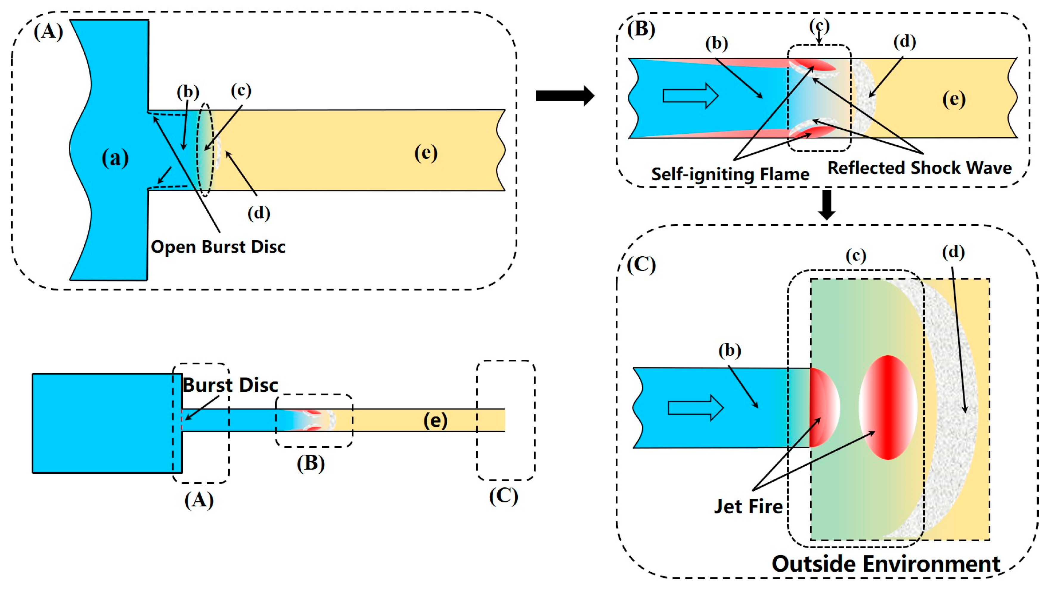
Figure 1. Schematic diagram of diffusion ignition principle. (A) The moment of rupture of the burst disc; (B) the ignition kernel generation process; (C) the process of flame development outside the tube. (a) High-pressure hydrogen; (b) hydrogen jet; (c) hydrogen–air mixture zone; (d) leading shock wave; (e) air.
Fire 07 00268 g001
Figure 2. Diagram of experimental device and partial influencing factors. (a) Hydrogen supply tank; (b) hydrogen reservoir; (c) burst disc; (d) extension tube.
Fire 07 00268 g002
Figure 3. Three typical pressure profiles and light signals [32].
Fire 07 00268 g003
Figure 4. Effect of impurity gases on the autoignition of hydrogen. (A) Autoignition conditions related to burst pressure at various methane addition concentrations [55]; (B) Comparison of the minimum discharge pressure necessary for the autoignition of different gases added to the tube [65].
Fire 07 00268 g004
Figure 5. Effect of burst disc opening size on hydrogen autoignition. (A) Ignition limits for unconstrained hydrogen release into the air [67,70,71,72]; (B) hydrogen autoignition at different opening ratios [31,43,69].
Fire 07 00268 g005
Figure 6. Effect of rupture process on hydrogen autoignition. (A) Relationship between the autoignition delay of hydrogen and the rupture rate of the burst disc [28]; (B) Influence of release tube length and release pressure on hydrogen autoignition [41].
Fire 07 00268 g006
Figure 9. Effect of tube construction on hydrogen autoignition. (A) Effect of tube length and release pressure on hydrogen autoignition in circular and rectangular tubes with a cross-sectional area of 20 mm2 [39,46,70]; (B) effect of release pressure on hydrogen autoignition in four types of variable cut-off tubes with lengths all 360 mm: local contraction, local enlargement, abrupt contraction, and abrupt enlargement [85]; (C) flow characteristics in a shock tube with spacers installed [80].
Fire 07 00268 g009
Figure 10. Schematic diagram of the spread of the shock wave in the Ω-shaped tube and right-angle tube. (A) A simple flow diagram of shock waves spread in an Ω-shaped tube [86]. (a) A leading shock wave is generated before the hydrogen jet, heating the air and traveling downstream; (b) the leading incident shock wave rapidly undergoes a transformation, adopting a spherical shape. (c) the first leading incident shock wave will hit the opposite wall of the bend, and a large portion of this incident shock wave will be reflected back upstream in the form of a reflected shock wave, which leads to the stagnation of the induced flow behind it; (df) the incident shock wave will reflect again, repeating the preceding procedure. (B) Three mechanisms of hydrogen autoignition under high pressure in L-tubes suggested by Gong et al. [87]. (g) Initial ignition takes place before the corner; (h) initial ignition takes place at the corner; (i) the initial ignition takes place on the inner wall downstream of the corner. (C) Three mechanisms of autoignition of high-pressure hydrogen in L-shaped tubes suggested by Pan et al. [88]. (j) Initial ignition takes place before the corner; (k) initial ignition takes place before the corner and quenches at the corner, and secondary ignition takes place before the nozzle; (l) the initial ignition takes place at the corner.
Fire 07 00268 g010
Figure 11. Schematic diagram of temperature distribution and ignition process [90]. Temperature distribution and schematic of ignition process. RSupper: reflected shock wave from upper obstacle; RSlower: reflected shock wave from lower obstacle; CS: contact surface; SW: leading shock wave. (AC) The two obstacles are symmetrically distributed on the upper and lower walls. (D) The two obstacles are asymmetrically distributed on the upper and lower walls.
Fire 07 00268 g011
Figure 13. (A) Three conditions for three types of communication behavior [83]. (B) Horizontal range of flame tip [74]. (C) Flame propagation and pressure history (P0 = 120 bar; Prupture = 35 bar) [109]. (D) Macroscopic phenomenon of jet flame close to the nozzle [32].
Fire 07 00268 g013
Table 1. Different storage solutions compared in a 1 km ride [4].
Compressed TankCryogenic TankFe-Ti HydrideMg Hydride
H2 consumption (gms)6.246.48.049.7
Direct energy required to travel (kJ)749
[0 (Base)
768
19
965.4
216.4
1164
415]
Energy required to produce and store H2 (kJ)1260.72172.71473.71777
Energy required to produce tank (kJ)34.2
[18.6
15.6
0 (Base)
177.3
161.7
60
44.4]
Total energy required (kJ)2043.92956.32616.43001.5
Table 2. Statistical analysis table of fire sources in hydrogen fire accidents [14,15].
Ignition SourceAstbury [14]Kingston University [15]
Number%Number%
Arson0030.44
Collision22.5294.29
Flame33.7588.58
Hot surface22.5578.43
Electric22.5446.51
Friction spark22.500
Not identified7086.341961.98
Non-ignition00669.76
Total81100676100
Table 3. Shock tube and burst disc parameters for opening ratio study.
AuthorYearCross-Sectional Shape and SizeExtension TubeBurst Disc MaterialOpening Ratio
Lee [31]2015Rectangle: 11 mm × 11 mm200 mmMylar polyester film1/4, 1/2, 3/4, 1
Gong [43]2019Circle: d = 15 mm360 mmNickel 2011/3, 1/2, 2/3, 1
Cha [69]2021Rectangle: 10 mm × 10 mm300 mmMylar polyester film1/8, 1/4, 1/2, 1
Disclaimer/Publisher’s Note: The statements, opinions and data contained in all publications are solely those of the individual author(s) and contributor(s) and not of MDPI and/or the editor(s). MDPI and/or the editor(s) disclaim responsibility for any injury to people or property resulting from any ideas, methods, instructions or products referred to in the content.