1. Introduction
As a burgeoning form of clean energy source, hydrogen energy has garnered global attention and is regarded as one of the most promising alternative fuels. However, numerous technical challenges persist, particularly concerning hydrogen safety. Among the fundamental topics within hydrogen safety, combustion, and fire science, the spontaneous ignition of suddenly released hydrogen has garnered widespread interest over the past few decades. Former researchers have put forward several hypotheses regarding hydrogen spontaneous ignition [
1], including the reverse Joule–Thomson effect, electrostatic ignition, diffusion ignition, sudden adiabatic compression, hot surface ignition, etc. However, a conclusive determination regarding the dominant factor of spontaneous ignition of suddenly released hydrogen has not yet been reached. It is commonly believed that hydrogen spontaneous ignition arises from the combined effects of some of these mechanisms rather than any single one individually.
In recent years, there has been considerable investigation into the spontaneous ignition behaviors of suddenly released hydrogen. Existing studies indicate that these behaviors are influenced by various factors, including burst pressure, tube geometry (such as length, diameter, elbow, and tee configurations), and gas additives. Mogi [
2,
3] conducted a series of experiments on hydrogen released into downstream straight tubes through burst disks. Their findings suggest that the probability of spontaneous ignition increases with tube length, and the ignition position tends to approach the burst disk as the release pressure rises. These conclusions are supported by Lee’s results [
4]. Golub [
5,
6,
7] observed that the shape of the tube section impacts the mixing of hydrogen and air in the boundary layer, thereby affecting the critical release pressure for spontaneous ignition.
Kitabayashi [
8] conducted experiments using relatively longer tubes (up to 4200 mm) to investigate the promoting or suppressing effects of tube length on spontaneous ignition behaviors. They found that the minimum diaphragm burst pressure of spontaneous ignition is between 1.0 and 1.2 m of the extension tube length. Similarly, Wang [
9] conducted a similar experiment but obtained a slightly different result for the tube length associated with the minimum diaphragm burst pressure (1.7 m). Rudy [
10] also concluded that spontaneous ignition behavior is more sensitive to tube length than cross-section geometry. Duan [
11] and Gong [
12,
13] conducted a series of experiments on hydrogen spontaneous ignition through burst disks, systematically revealing the effects of tube length, diameter, and geometry.
All the aforementioned experimental studies employ metallic tubes and in-situ sensors to capture both the flame and overpressure signal during the hydrogen release process., leaving the flame ignition and propagation behavior invisible. To directly observe the ignition and propagation behavior of hydrogen flame during release, Kim [
14] conducted experiments using transparent tubes and high-speed cameras. Their work unveiled the process by which the spontaneously ignited flame, initiated at the boundary layer, propagates toward both the front and the tail of the mixing zone. With a separate experiment employing round-section transparent tubes, Kaneko [
15] demonstrated that hydrogen-air mixing initiates near the sidewall of the tube, further inducing spontaneous ignition. This conclusion was corroborated by Yamashita [
16]. Zeng [
17] also employed a similar experimental setup to validate these findings.
Typical experimental setups have been summarized in
Table 1. It should be noted that the diaphragm and burst disk have similar mechanisms, which rupture suddenly and release the compressed hydrogen rapidly. The difference is that in previous works, the diaphragm is often regarded as PRD broken with a needle, while the burst disk ruptures spontaneously as upstream pressure exceeds its set pressure.
Several conclusions can be drawn based on the aforementioned works:
- (1)
Previous research has predominantly focused on the spontaneous ignition behavior of hydrogen released through burst disks and diaphragms, overlooking hydrogen released through safety valves. Safety valves are a crucial type of pressure relief device (PRD) in the hydrogen energy industry, yet they have been scarcely investigated in existing studies.
- (2)
The majority of previous studies utilized gas cylinders as the source of hydrogen, thereby limiting the release pressure to approximately 10 MPa. Consequently, the spontaneous ignition behavior of suddenly released hydrogen at pressures exceeding 10 MPa remains undisclosed.
The present study aims to address these gaps by experimentally investigating the shockwave and flame behavior of high-pressure hydrogen released through various types of PRDs, with the goal of unveiling and quantifying its evolution.
2. Experimental Setup
The experimental setup, depicted in
Figure 1, begins with the sourcing of hydrogen from hydrogen cylinders, each providing a maximum pressure of 10 MPa. The hydrogen undergoes compression via a two-stage air-driven compressor, achieving pressures of up to 140 MPa with an accuracy of 0.1 MPa. Subsequently, it is stored in a high-pressure tank. A pressure sensor (SENEX (Fuzhou, China), DG1300-GY-B-2-200/GE/GW/FZ) is employed to monitor the pressure within the high-pressure tank, facilitating the measurement of both the actual hydrogen release pressure (
P0) and the pressure drop experienced by the tank during release. The controlled release of hydrogen at specific pressures is executed through Pressure Relief Devices (PRDs), directing the flow into a downstream release tube. This tube, with a length of 1800 mm (a standard configuration for hydrogen tube trailers) and an inner diameter (
D) of 10 mm, serves as the primary conduit for the released hydrogen. To capture and analyze the dynamics behaviors of the released hydrogen, four high-frequency (500 kHz) pressure transducers (PCB (Buffalo, NY, USA) Piezoelectric, 113B22) are strategically mounted along the release tube. These transducers are positioned at distances of 180, 650, 1120, and 1590 mm from the PRDs, respectively, to enable the measurement of shockwave overpressure. Additionally, to monitor the presence and behavior of the hydrogen flame within the tube, four light detectors (Thorlabs (Newton, NJ, USA), Si photodiode, FDS010) are symmetrically installed alongside the pressure sensors, which have a light signal wavelength range of 200–1100 nm, covering the emitting wavelength range of hydrogen flame, which ensures effective capture of potential spontaneous ignition inside the tube. This arrangement facilitates the capture of light signals emitted by the flame. The releasing process of burst disks was tested with nitrogen before employing hydrogen. No light signal emerges in nitrogen cases. Therefore, the light does not accumulate from the rupture of the burst disk, which ensures the absence of external distraction. The velocity of both the shockwave and the flame is calculated by analyzing the time difference between signals received by adjacent sensors and considering their respective inter-distances. Furthermore, an HD infrared camera is utilized to provide visual monitoring of any potential jet flames formed outside the tube. Following the experimental procedures, the system is purged with nitrogen to ensure safety and mitigate any residual risks associated with hydrogen handling. It should be noted that the release path is shut off after releasing in safety valve cases because the disk of the safety valve resets under the pressure of the spring as upstream pressure drops. This creates a dead end in the releasing tube near the safety valve. In order to ensure safety, the downstream tube was disconnected after each safety valve case and then purged with nitrogen and air in sequence to prevent any direct contact of hydrogen and air between experimental cases.
In the hydrogen energy industry, burst disks are mostly employed as PRD on vessels with relatively low storage pressure (tube trailers, bundles, etc.), while safety valves are used with a much wider storage pressure range (up to 140 MPa). Therefore, typical burst disks with set pressure up to 49.5 MPa are tested in this current work, with safety valves with the same set pressure tested to investigate their shockwave and flame characteristics. Meanwhile, safety valves with higher set pressure (up to 140 MPa) are employed to further reveal their fire risk in industrial applications.
Burst disks (
Figure 1b) and safety valves (
Figure 1c) serve as the pressure relief devices (PRDs) in the experimental setup. The burst disks are constructed from 316L stainless steel, have an inner diameter of 10 mm, and are fixed between the high-pressure tank and release tube by a set of holders made of 316L stainless steel, which has a maximum allowed pressure of 60 MPa. They are designed to rupture at pressures ranging from 22 to 49.5 MPa. Once
P0 exceeds its set pressure, the burst disk ruptures and releases hydrogen into the downstream tube suddenly. Safety valves have set pressures ranging from 22 to 140 MPa. These valves are equipped with nominal diameters of 6 mm for set pressures below 100 MPa and 2 mm for set pressures exceeding 100 MPa and fixed between the high-pressure tank and release tube by build-in high-pressure thread connection. The lifting of safety valves (releasing of compressed hydrogen) is controlled by the stiffness of an internally installed spring (compressed by upstream pressure). Once the pressure in the hydrogen storage tank reaches or exceeds
P0 of the safety valve, the spring is compressed, allowing the compressed hydrogen in the high-pressure tank to be released through the safety valve.
During the experiments involving burst disks, the pressure within the hydrogen storage tank is set to the designated rupture pressure (set pressure, P0) of the burst disk. In contrast, for experiments involving safety valves, the tank pressure is adjusted to either the set pressure or slightly higher values (1 and 1.1 times the set pressure). This variation allows for the observation of shockwave and flame behaviors under conditions corresponding to both slightly and fully lifted safety valve scenarios.
The experimental procedure is as follows: firstly, the air inside the system is purged by nitrogen and hydrogen in sequence; secondly, the air-driven compressor is generated to gradually feed the high-pressure tank with hydrogen until its inner pressure reaches P0 of the pre-installed PRD; thirdly, the releasing takes place, along with the overpressure and light signal as well as jet flame image (if any) captured by the data acquisition system automatically; finally, the PRD is replaced to get ready for the next experimental case.
The entire experimental system is effectively grounded to avoid potential spark ignition. All experimental cases are repeated three times to reduce random error, which is displayed on figures through error bars.
3. Results and Discussion
3.1. Hydrogen Released through Burst Disks
Experiments are conducted using burst disks with rupture pressures of 22, 25, and 49.5 MPa, with representative pressure and light signal data presented in
Figure 2. Analysis reveals a rapid increase in pressure detected sequentially by all four pressure transducers, indicating the formation, propagation, and subsequent attenuation (gradual decrease in overpressure) of a leading shockwave downstream of the tube.
Furthermore, it is noteworthy that spontaneous ignition of hydrogen is observed in all three cases, as evidenced by the light signals captured by the light detectors. In the case of the highest release pressure (49.5 MPa), the flame persists throughout the length of the tube. However, in the instances where the release pressures are 22 and 25 MPa, the light signal is only captured by L1, which indicates that the flame extinguishes along the tube.
Mogi [
3] categorized the outcomes of suddenly released hydrogen into three cases: successful ignition, failed ignition, and no ignition of the jet flow. In this context, “successful ignition” refers to the sustained presence of flame inside the tube accompanied by the presence of a jet flame outside the tube, and “failed ignition” refers to the absence of jet flame with spontaneous ignition of hydrogen takes place inside the tube, while “no ignition” indicates no flame at all. It can also be drawn from previous works that a steady, sustained flame propagation is guaranteed by the jet flame observed outside the tube. However, it is noteworthy that in the current study, a jet flame is observed in all three cases, despite the extinguishment of the flame inside the tube when
P0 is relatively low (as depicted in
Figure 2b,d). This observation differs from findings in previous works with relatively low
P0. The presence of the jet flame in these cases may be attributed to the phenomenon of hot hydrogen re-igniting upon contact with oxygen-rich ambient environments outside the tube. Thus, it can be concluded that higher release pressure delays the extinguishment of the flame inside the tube. However, the presence of a sustained flame inside the tube does not guarantee the absence of a jet flame, which is one of the main causes of fire disasters in the high-pressure hydrogen industry. The possibility of re-ignition should be taken into consideration during operation.
Figure 3a displays the measured shockwave intensity represented in terms of pressure (
P) plotted against the transducer-PRD distance (Δ
L) for all tested burst disk conditions. As the transducer-PRD distance (Δ
L) varies, the pressure (
P) exhibits a trend reminiscent of an exponential decline (as described by Equation (1)), indicating the attenuation of shockwave intensity over distance.
In which
a implies shockwave overpressure near the PRD (Δ
L = 0),
b and
c indicate the decline rate of shockwave overpressure with increasing Δ
L. It can be drawn from
Figure 3 that
b and
c are in positive correlation with
P0, which indicates that overpressure declines faster during releasing with higher
P0. Meanwhile,
P is positively correlated with
P0.
P and Δ
L are further normalized to
P* (
P* =
P/
P0) and
L* (
L* = Δ
L/
D). It shows that the decreasing behavior can be represented reasonably well by an exponential function in the form of Equation (2) (
Figure 4).
Shockwave velocity (
v) also shows decline behavior with increasing Δ
L.
v at the position of
P1–
P4 is calculated based on Δ
L and pressure signal time difference (Δ
T), as in Equation (3), and demonstrated in
Figure 3b.
v shows a decline linearly with increasing Δ
L and a positive correlation with
P0.
3.2. Hydrogen Released through Safety Valves
In contrast to burst disks, safety valves operate differently when the upstream pressure reaches the designated release pressure (P0). At this point, the valve’s disk and connecting spring are compressed, causing the partial opening of the relief nozzle (referred to as a slightly lifted condition). However, if the upstream pressure exceeds the excess pressure of the safety valve (typically not exceeding 1.1 times P0), the valve rapidly opens to fully expose the relief nozzle, as per its design. Therefore, compared to burst disks, which execute sudden relief through rupture, safety valves with equivalent relief pressures may exhibit different overpressure and flame behaviors due to their distinct operational mechanisms.
Figure 5 illustrates a typical overpressure history of hydrogen released through a safety valve with a designated release pressure (
P0) of 105 MPa. It is evident that as the upstream pressure reaches
P0, sequential jump signals are observed at positions labeled
P1 through
P4. However, these signals exhibit significantly lower peak values and overpressure rise rates compared to those observed with a burst disk, even when the burst disk has a much lower
P0. This discrepancy arises from the distinct lifting mechanisms of different PRDs. Safety valves regulate the release through the gradual compression of the disk and connecting spring, leading to the progressive opening of the relief nozzle. In contrast, burst disks achieve rapid release by rupturing, resulting in a larger overpressure rise rate. Moreover, unlike the continuous overpressure observed in burst disk cases, the disk of safety valves gradually reseats as the upstream pressure declines, eventually shutting off the relief nozzle (around
t = ~−1.6 s). Subsequently, a brief period of negative pressure ensues, followed by a gradual rise in pressure back to ambient levels. This negative pressure phase corresponds to a pressure lower than the ambient, which may caused by the continuous momentum of hydrogen. After the releasing path is shut off by the safety valve, the released hydrogen keeps expanding and moving towards the exit, hence the rapid pressure drop inside the tube.
It is noteworthy that spontaneous ignition of hydrogen does not occur in any of the safety valve cases, even up to a set pressure of 140 MPa. This absence of spontaneous ignition is attributed to the relatively low overpressure rise rate during release, leading to the lack of a leading shockwave. Consequently, hydrogen is not effectively adiabatically compressed, thereby precluding spontaneous ignition. In the absence of hot surfaces (no external ignition source) and electrostatic ignition (due to effective grounding) in all experimental scenarios, adiabatic compression emerges as the primary influencing factor for spontaneous ignition.
To validate the assumptions made earlier, the overpressure histories of safety valves under different lifting conditions (slightly and fully lifted) are compared in
Figure 6. It is evident that despite the fully lifted case having only a 10% higher
P0, the overpressure recorded by
P1–
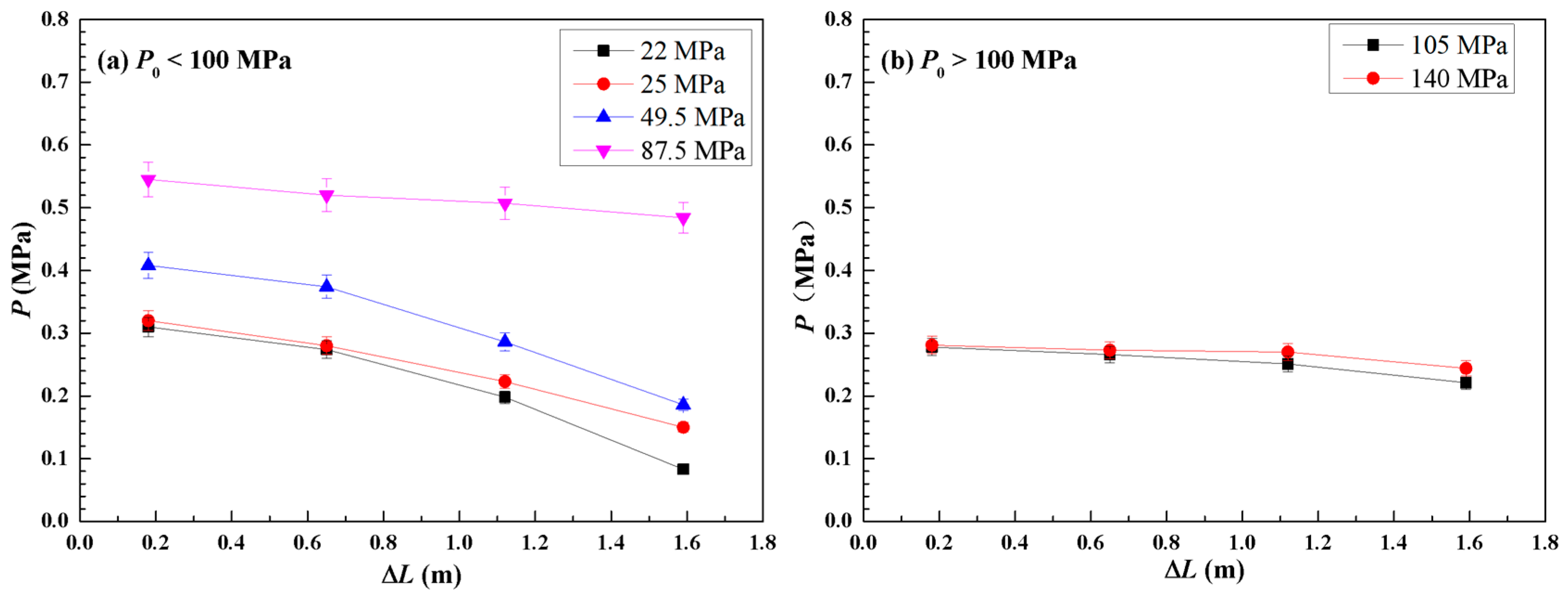
P4 in the fully lifted case is more than twice that of the slightly lifted case. Additionally, the overpressure rise rate is significantly larger for the fully lifted case. The evolution of the overpressure peak value in slightly lifted cases is illustrated in
Figure 7. It is evident that both
P0 and the nominal diameter have a combined impact on the overpressure peak value. As
P0 increases, the overpressure peak value also increases while its rate of decline decreases. However, when
P0 exceeds 100 MPa, the overpressure peak value starts to drop. This drop is attributed to the change in nominal diameter from 6 mm to 2 mm. Nonetheless, the decline rate further decreases with increasing
P0.
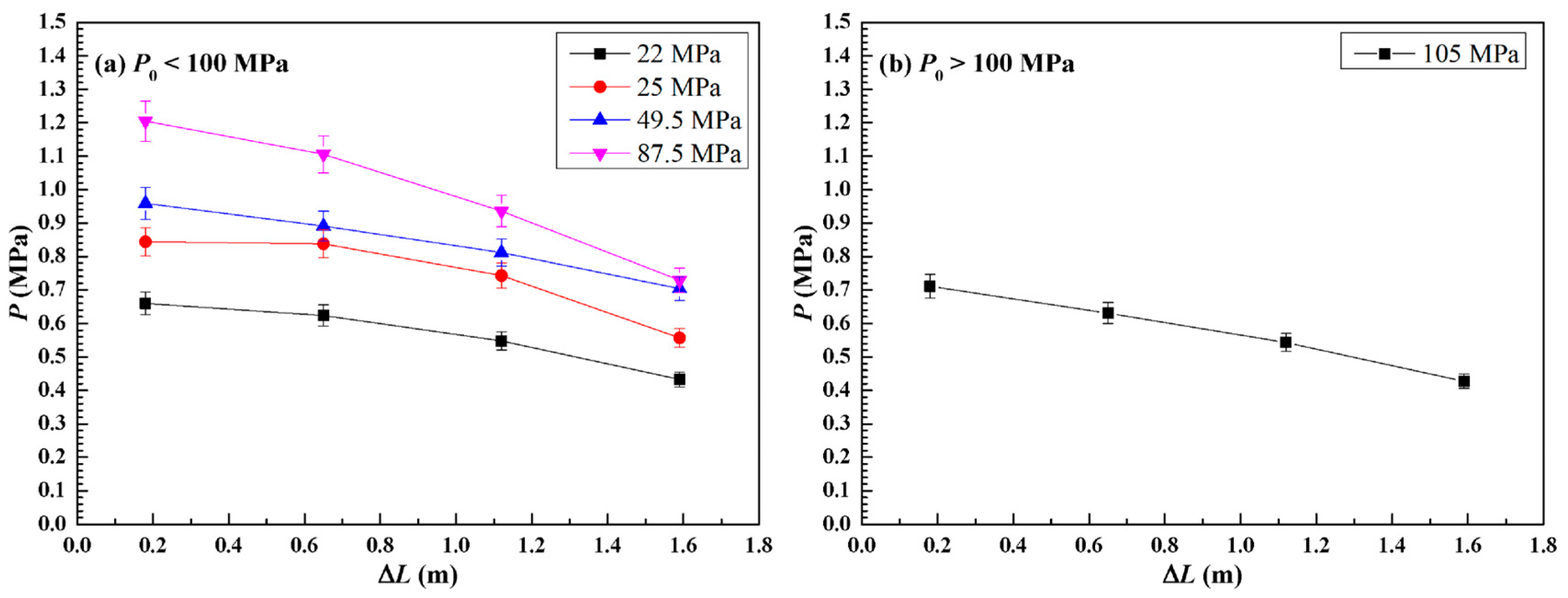
The evolution of the overpressure peak value in fully lifted cases is depicted in
Figure 8. However, it is important to note that the 140 MPa fully lifted experiment was not conducted due to the output limit of the compressor.
3.3. Overpressure Characteristics Comparison of Different PRDs
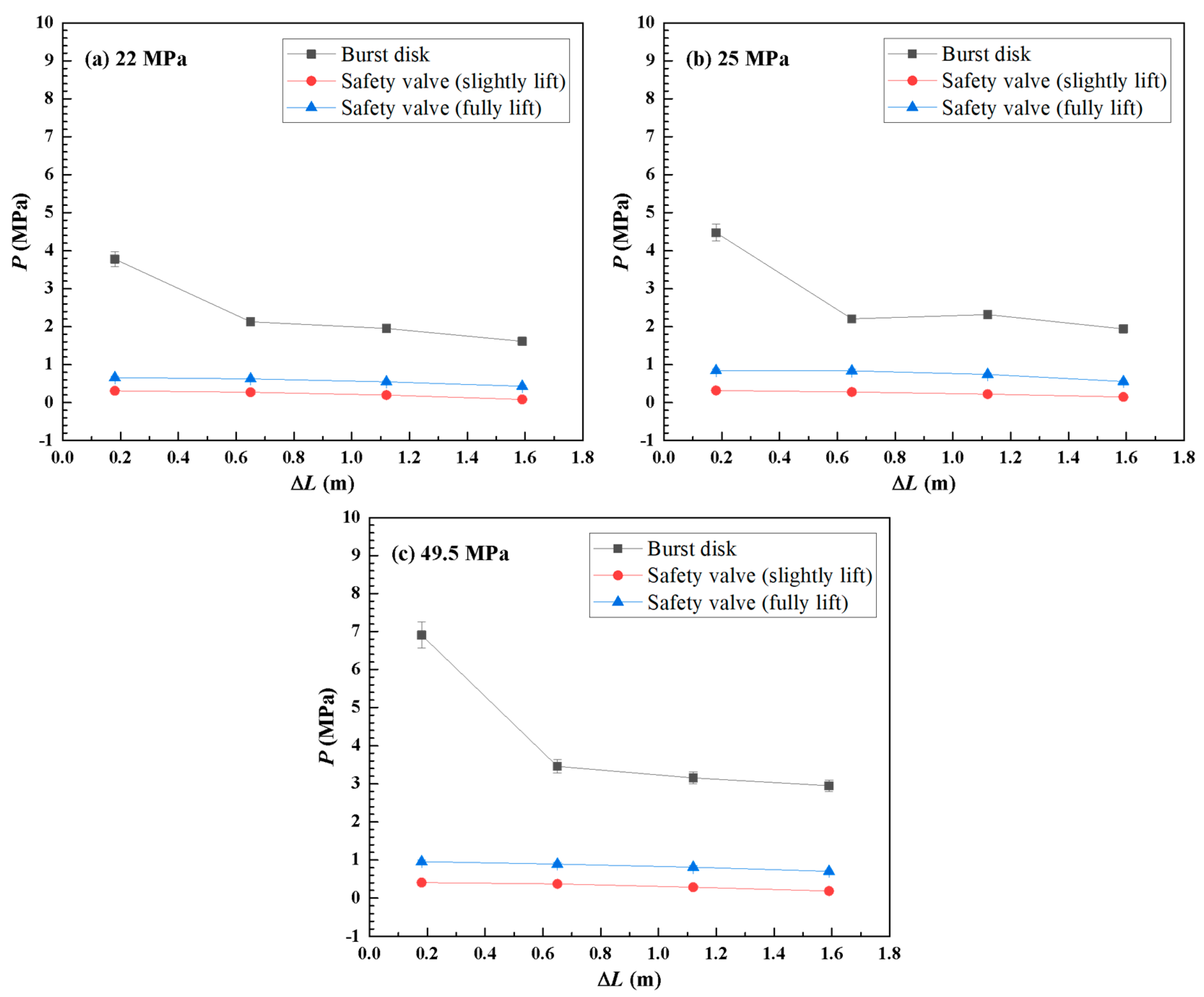
The lateral comparison of overpressure evolution between burst disks and safety valves is presented in
Figure 9. Notably, the overpressure values of burst disks are approximately 6 to 7 times higher than those of safety valves (under 1 MPa) with the same
P0. This higher overpressure value indicates stronger adiabatic compression of hydrogen, thereby increasing the likelihood of spontaneous ignition.
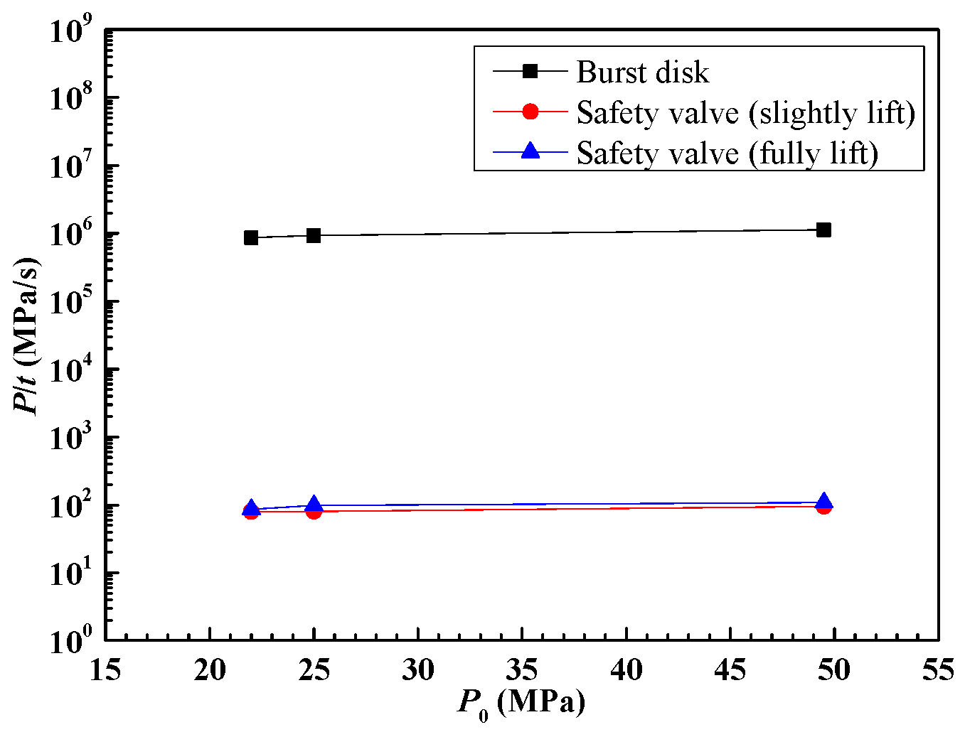
Furthermore, in addition to the overpressure value, the overpressure rise rate (
P/
t) also plays a significant role in hydrogen spontaneous ignition, a factor that has not been thoroughly addressed in previous studies. As illustrated in
Figure 10, the overpressure rise rate of burst disks is approximately 10 × 10
6 MPa/s, while that of safety valves is only about 10 × 10
2 MPa/s, roughly one ten-thousandth of the former. As a result, the mixture of hydrogen and air is effectively adiabatically compressed when employing a burst disk as PRD, which induces spontaneous ignition and following jet flame. This substantial difference can be attributed to the distinct mechanisms employed by these two types of PRDs, which have been thoroughly analyzed in
Section 2.
Burst disks rapidly open the relief path by rupturing, facilitating the formation of a shockwave characterized by a high overpressure rise rate. This shockwave, in turn, compresses the hydrogen/air mixture, thereby inducing spontaneous ignition of hydrogen. In contrast, the relatively slow-opening safety valves are less likely to generate a shockwave, resulting in the absence of spontaneous ignition in all cases.
4. Conclusions
This current work conducts an experimental investigation into the shockwave and flame characteristics of compressed hydrogen (up to 140 MPa) released through various types of PRDs. The key findings can be summed up as follows:
- (1)
All burst disk cases experienced spontaneous ignition, while no safety valve case did. This discrepancy arises from the distinct lifting mechanisms of different PRDs, which affects the overpressure value and rising rate. When the usage scenario allows, safety valves should be prioritized to minimize the risk of hydrogen spontaneous ignition;
- (2)
A special phenomenon of self-extinguishment inside the pipe is observed when the P0 of burst disk cases is relatively low, followed by reigniting outside the pipe, which forms a jet flame (one of the main causes of fire disasters in the high-pressure hydrogen industry). The self-extinguishment of the flame inside the pipe does not guarantee the absence of jet fire, which should be taken into consideration when operating fire risk assessment of high-pressure hydrogen facilities and stations;
- (3)
The decline in shockwave intensity, measured in terms of pressure, can be effectively modeled by a dimensionless exponential function (Equation (2)).
Safety valves demonstrate significantly lower overpressure values and rise rates compared to burst disks. The latter is considered a primary factor influencing the occurrence of shockwaves, thus leading to the absence of spontaneous ignition. It is important to acknowledge that the present study exclusively utilized straight pipes. The potential coupling effects of pipe structures (e.g., elbows, tees, diameter variations) in conjunction with different PRD types on shockwave overpressure and spontaneous ignition behaviors have not been explored and analyzed in this research. Furthermore, there is a need for additional investigation into the characteristics of other types of PRDs, such as relief needle valves, which are also widely applied in the high-pressure industry. Another burgeoning form of hydrogen storage/transportation is hydrogen-doped natural gas, whose shockwave and flame characteristics during leakage and release have not been investigated yet. It is urgent to conduct relevant numerical and experimental works to reveal the aforementioned research points to effectively assess the fire risk of hydrogen-doped natural gas.


