Article

Study on the Configuration and Fire-Resistant Property of Cable Tunnel Fireproof Clapboard Based on Equivalent Fire Condition Testing

1
State Grid Beijing Electric Power Research Institute, Beijing 100075, China
2
State Grid Beijing Electric Power Company, Beijing 100031, China
*
Author to whom correspondence should be addressed.
Fire 2024, 7(10), 357; https://doi.org/10.3390/fire7100357
Submission received: 29 August 2024 / Revised: 28 September 2024 / Accepted: 6 October 2024 / Published: 9 October 2024
(This article belongs to the Special Issue Advances in Fire Prevention and Control for Power Grids)

Abstract

:
At present, the selection criteria and configuration methods for fireproof clapboards in cable tunnels are not yet perfect, making it difficult to achieve effective fire protection. Therefore, an equivalent fire condition testing method is proposed to analyze the fire-resistant property of fireproof clapboards of different materials. Firstly, a tunnel fire experiment platform was built to carry out the combustion experiment of the high-voltage cable intermediate joint. The cable combustion equivalent fire source device is developed based on the temperature rise characteristics under different combustion conditions. However, the temperature rise characteristics of the equivalent fire source and the actual cable combustion error are within 10%. Then, four typical fireproof clapboards were tested under equivalent fire sources. The results indicate that the organic molded board has the best performance. In addition, factors such as the thickness, side panel height, and installation method of the fireproof clapboards were tested and analyzed. The results indicate that a minimum thickness of 5 mm for the fireproof clapboard and a height of 200 mm for the side panel of the clapboard are necessary to ensure effective protection. The installation method of hoisting fireproof clapboards can effectively extend the protection time by about 30% compared to the flat method.

1. Introduction

In recent years, cable consumption has become larger and larger with the cable tunnel growing rapidly. Cable tunnel fire accidents emerge in an endless stream [1,2,3,4,5]. The fire prevention facilities in the tunnel are diversified. Fire prevention measures such as fire extinguishing bombs or vertical shafts are generally used in the vertical direction, and fireproof clapboards are commonly used in the horizontal or inclined direction [6]. The fireproof clapboard is laid directly below the cable to block the burning effect of the lower cable on the cable in this channel when the lower cable burns. The fireproof clapboard will be the first barrier to block the fire source in the event of a fire in the lower cable. The fireproof clapboard not only prevents the flame from spreading upward but also effectively delays the time when the cable above the fire source is ignited [7]. However, in a new cable fire accident in a tunnel in Beijing in 2023, though the fireproof clapboard is added below the cable, the cable is still ignited because of its insufficient fire resistance. In addition, the height of the side plate above the cable intermediate joint of the tunnel is not high enough, and the fire plume is covered by the cable intermediate joint to cause the outer sheath damage accident. The accidents not only led to the burning of the cable outer sheath but also affected the burning damage of the other cable outer sheath in the same tunnel. Hence, given the unclear fire performance of the fireproof clapboard and the imperfect fire protection configuration, it is urgent to carry out further research on the Protective Performance and the Configuration of the fireproof clapboard.
Previous studies focused on the fire prevention measures and fire detection of the fireproof clapboard laid in the cable tunnel [8,9,10]. Many scholars only focus on this study of cable fire spread, smoke temperature distribution, combustion characteristics, and decomposition mechanisms [11,12]. Ding et al. [13] found through simulation that the laying of fireproof clapboard and firewalls in cable tunnels can effectively slow down the spread of fires, reduce the generation of toxic gases, and reduce the temperature of fires in tunnels. Pu et al. [14] lay L-shaped fireproof clapboards with different side plate heights for simulation and analyze the heat insulation effect of L-shaped fireproof clapboards with different side plate heights by establishing a cable tunnel model. The results show that the optimal side plate height corresponding to different grades of cable is obtained. However, the aforementioned research fails to study the protective performance of the fireproof clapboard. In particular, most of the existing studies are simulation studies, but experiments showed that the thermal insulation properties of the fireproof clapboard changed during the fire process. In addition, problems still occur when fire-resistant clapboards that are routinely tested and meet building fire protection standards are applied to cable tunnel fires. The standard of fireproof clapboard is mostly used in buildings, and its performance is not applicable to tunnels. Thus, it is necessary to use the equivalent fire source to test the clapboard and to study the unified application standard of the clapboard and the comparative analysis of different clapboards so as to obtain its protective performance more accurately.
An equivalent fire source condition method based on actual fire is proposed to study the Protective Performance and Configuration of four typical fireproof clapboards in the cable tunnel. Firstly, the tunnel fire test platform is built, and the external fire source is simulated by the propane gas cylinder with the controllable valve to adjust the power. The independent combustion test is carried out on the cable intermediate joint, and the equivalent fire source is simulated and developed according to the temperature characteristics. Then, the equivalent fire source is used to test combustion performance and the bearing capacity of four typical fireproof clapboard materials. The results show that the organic molded board with the best performance is selected. Finally, the fire condition testing is carried out on the influencing factors of the thickness, side plate height, and the hoisting or flat installation methods. The protective performance is analyzed, and the optimal configuration scheme is proposed.

2. Experimental Platform and Equivalent Simulation of Cable Combustion

Fireproof clapboards used in cable tunnels have many types. To test all types of fireproof clapboards is difficult to achieve. In addition, the unstable combustion results of the intermediate joint of the cable in each test will cause errors, and the test cost will be high. Therefore, it is urgent to conduct research on cable fires to obtain changes in cable combustion power. Moreover, a stable and controllable source of fire for subsequent fire performance testing of fireproof clapboards will be provided.

2.1. Combustion Test Platform

A test platform for simulating cable tunnels has been built, as shown in Figure 1. On this platform, cable combustion tests can be conducted, and the cable combustion process can be monitored to obtain the temperature rise characteristics of combustion. In addition, fire resistance property testing of fire clapboards can be conducted on the platform.
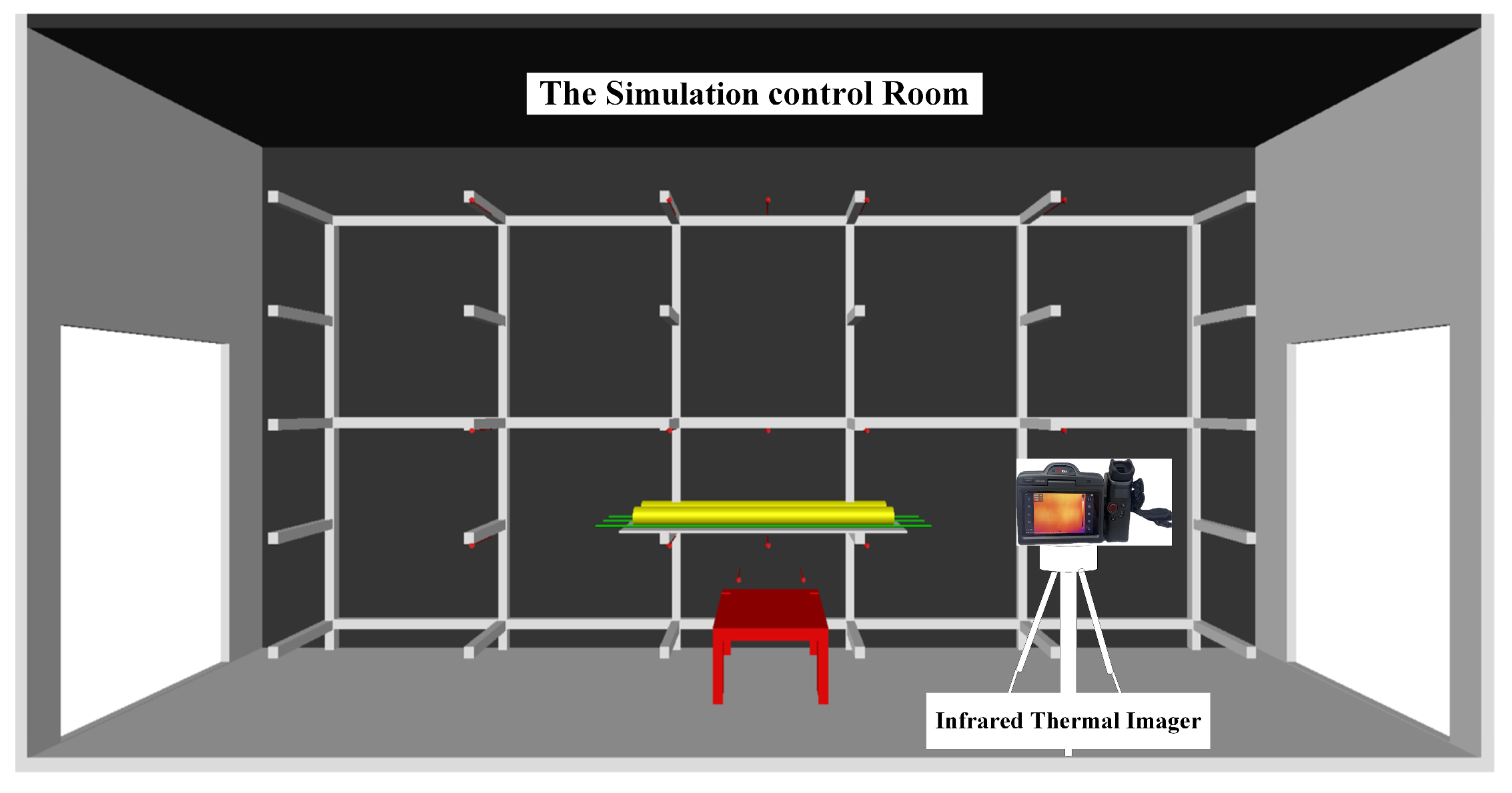
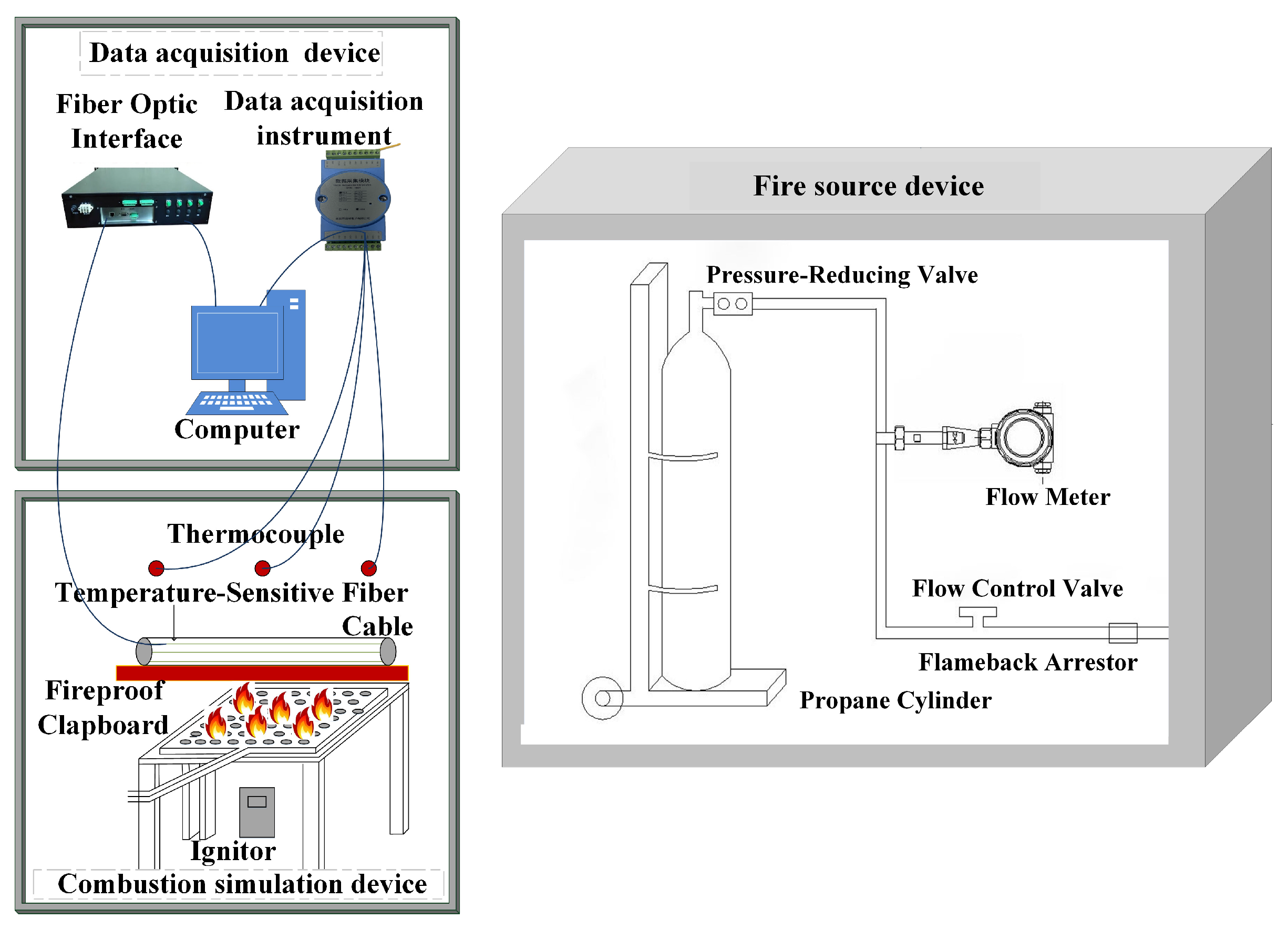
An equal-scale model based on the actual cable tunnel for testing was built to truly replicate the fire development trend in the cable tunnel. The size of the tunnel with a rectangular cross-section is 2.3 m × 2.3 m × 6 m. One of the walls is installed according to the actual arrangement of the brackets in the tunnel. The bottom bracket is 0.6 m from the ground, and the vertical distance between the brackets of each layer is 0.4 m. The other wall is provided with transparent fire-resistant glass for experimental observation, as shown in Figure 2. The actual combustion room is connected to the control room, and the control room has the data acquisition device and fire source device, as shown in Figure 3.
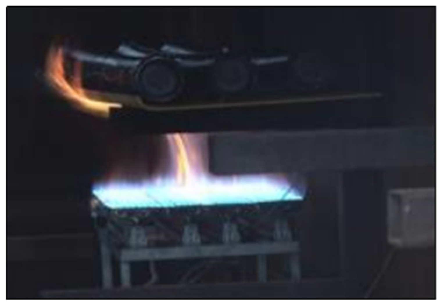
The propane burner with controllable fire source power is used as the fire source device, and the ignition row with a size of 0.5 m × 0.5 m is used to simulate the local cable fire. The test under different working conditions is simulated by configuring a movable, adjustable height bracket. The ignition row is placed at the first layer of the bracket to simulate the cable combustion. The second layer of the cable bracket is arranged with different material types of fireproof clapboards. The center of the ignition row is aligned with the center of the fireproof clapboard.
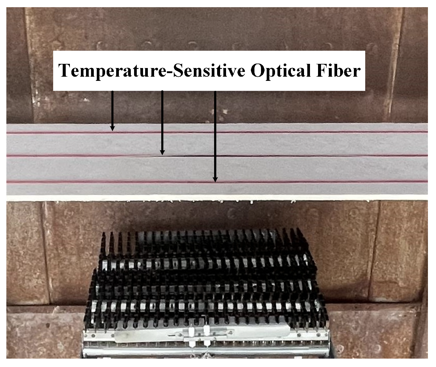
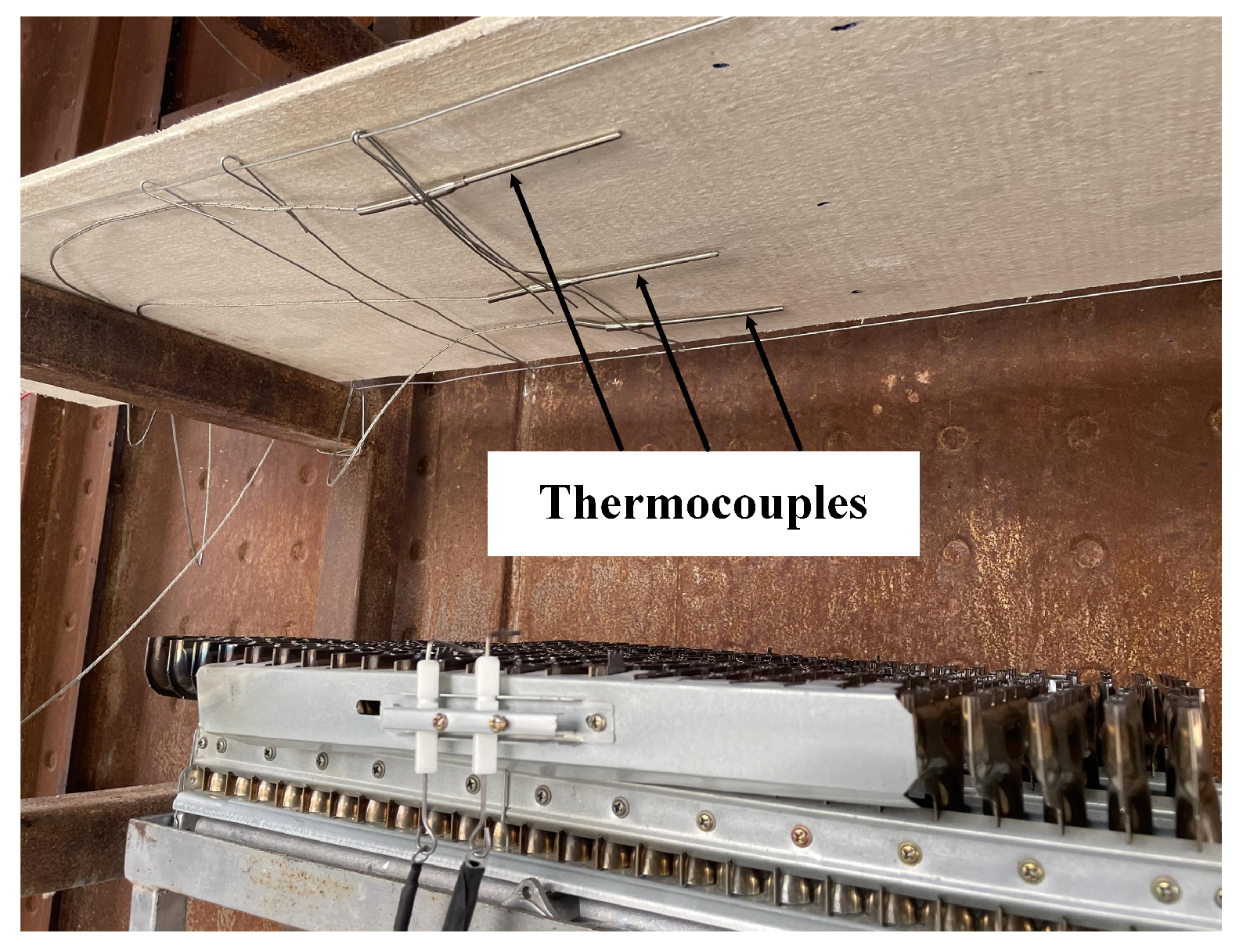
When testing the performance of fireproof clapboards, their arrangement is as follows: The fire-facing surface of the clapboard is in contact with the flame, and the temperature is high. The thermocouple is used to collect the temperature of the fire-facing surface of the clapboard for testing. Three thermocouples were arranged above the fire source below the fireproof clapboard, and their positions were 0.06 m, 0.2 m, and 0.34 m from the outer edge of the fireproof clapboard. The temperature of the fireproof clapboard surface above the fire source was recorded, as shown in Figure 4. To measure the temperature of the characteristic points on the protective surface of the fireproof clapboard in the test, the distributed optical fiber temperature measurement system is used to collect data in space, as shown in Figure 5. The spatial resolution of the fiber optic temperature measurement system is 0.5 m. The temperature-sensitive optical fiber was arranged in parallel at the contact between the cable and the clapboard on the protective surface of the fire clapboard. The position was 0.06 m, 0.2 m, and 0.34 m away from the outer edge of the clapboard from the outside to the inside, and the temperature change of the protective surface of the clapboard is recorded. In addition, the cables were arranged above the fireproof clapboard, and their positions were 0.06 m, 0.2 m, and 0.34 m away from the outer edge of the fireproof clapboard, respectively.

2.2. Cable Self-Combustion Test

The fire source setting in the numerical simulation of cable tunnel fire includes the following three types: (1) The initial fire source is defined in the simulation process. Under the action of the initial fire source, the cable is pyrolyzed and burned. The combustion rate depends on the heat provided by the environment. However, the heat release rate and duration of the initial fire source have no clear reason [15]. (2) The fixed area fire source is defined, and the determined heat release rate is set, which is the overall power of the fire. The corresponding combustion performance of the cable is not given. The simulated fire is only maintained in the same position, and its power is not changed from the initial to the end [16,17]. (3) The fixed area fire source is defined, and the fire development of the tunnel is set according to the material combustion heat release rate growth model. It is determined by Equation (1), but this method does not consider the early development of the fire and only simulates the effective combustion stage of the fire.
q = a t 2
where q is the heat release rate (kW); a is the fire growth factor (kW/s2), based on the PVC combustion growth factor in NFPA [18], take 0.04689; t is the combustion time (s).
Comparing the three fire source setting methods, the first method is more in line with the actual situation of cable tunnel fire development. Thus, the surrounding cables are pyrolyzed and burned and spread to different locations of the tunnel under the action of the initial fire source that results in a fire. However, the initial fire source in the simulation must be reasonably set and quantified according to the test. According to the relevant report [19,20], the combustion test and statistics of different types of cables laid horizontally are carried out, and the mathematical model of cable combustion is established. The overall continuous combustion time is as in Equation (2).
Δ t = 6 m c Δ H 5 q
where ∆t is the duration of cable burning (s); mc is the mass of cable fuel per unit area (kg/m2); ∆H is the heat of combustion (kJ/kg), 16 MJ/kg; q is the heat release rate per unit area of the cable (kW/m2).
The combustion power of 110 kV cable with a cross-sectional area of 800 mm2 is tested in this test. According to the short-circuit arc test of 110 kV and 220 kV voltage grade lines by scholar M. Kizilcay [21], the short-term power of 110 kV line short-circuit arc is between 2–7 MW. This research studied by Liang shows that the actual 110 kV line short-circuit fault removal time is about 0.7 s [22].
According to IEC 60695-2-11-2021 [23], the glow-wire flammability test method for end products inspires the fireproof clapboard test in cable tunnels. The propane gas cylinder is used to simulate the external fire source ignition cable in the test. The simulation fire source supply time is set to 0.7 s, and the short-term power of 2 MW and 7 MW short-circuit arc is taken. Hence, the corresponding actual ignition energy is 1.4 MJ and 4.9 MJ, respectively, as shown in Table 1. The flow rate of propane gas at which the flame reaches the ignition energy is large, and the arc ignition energy is concentrated. Therefore, it is impossible to ignite or turn off the simulated fire source quickly in a short time by using a propane gas cylinder to simulate the external fire source to ignite the cable experiment. The same ignition time is set to 10 s under the condition that the total combustion energy is stable, and the fire source power in the actual combustion experiment is calculated to be 140 kW and 490 kW, respectively, in the experiment. Propane is used as the simulated fire source, and the power of the fire source is controlled by the flow automation control valve according to this research on chemical substances, as shown in Equation (3).
q = m Δ H
where q is the heat release rate, i.e., the power of the fire source, (kW); m is propane mass flow rate, (g/s); ∆H is the effective combustion heat of propane, (kJ/g), take 46.4 (kJ/g).
The calculated gas flow rates of propane are 3.02 g/s and 10.56 g/s, respectively, as shown in Table 1 below. Then, the cable intermediate joint is ignited, and the fire source is removed to make it burn autonomously. The condition test of cable autonomous combustion ignited by the arc is simulated.
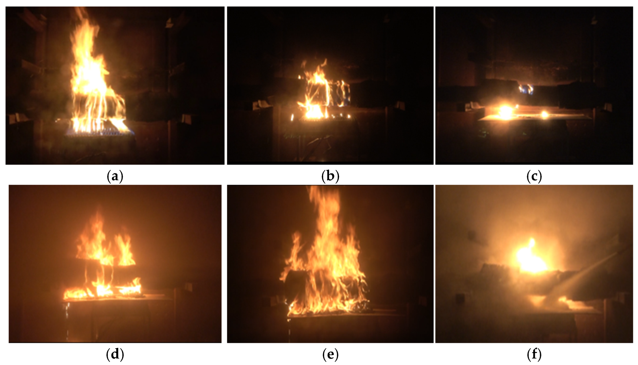
The self-combustion process of the cable intermediate joint is shown in Figure 6. Firstly, the ignition emission is placed directly below the cable intermediate joint. After ignition for 10 s, the intermediate joint is ignited, as shown in Figure 6a. After ignition, the fire row is removed. At the initial stage of combustion, the fire of the cable intermediate joint is determined by self-combustion. Compared with the external ignition, the fire becomes smaller. Then, the polyurethane at the combustion of the intermediate joint is gradually ignited, and the molten material drops on the fireproof clapboard and continues to burn, as shown in Figure 6b. Because the middle joint of the cable in the actual cable tunnel is the key fire protection zone, the fireproof clapboard is often placed at the middle joint of the cable to prevent the molten material from dripping and igniting the lower cable after the fire to restore the actual fire environment. Then, the middle joint begins to burn, as shown in Figure 6c. In the middle of the combustion, as the cable intermediate joint filler polyurethane and a small amount of insulation layer continue to burn, the dripping molten material increases and drops to the separator to fuel the joint combustion fire, and the flame spreads to both sides, as shown in Figure 6d. In the later stage of burning, the flame generated by a large number of molten drippings wraps the whole joint with the development of the fire. The combustibles at the middle joint of the cable continue to burn. The fire further increases, and the flame can reach the third layer under the support of internal and external flames. The fire of the bracket is out of control, lasting more than half an hour, as shown in Figure 6e. At the end of combustion, the fire is uncontrollable and needs to be extinguished, as shown in Figure 6f.
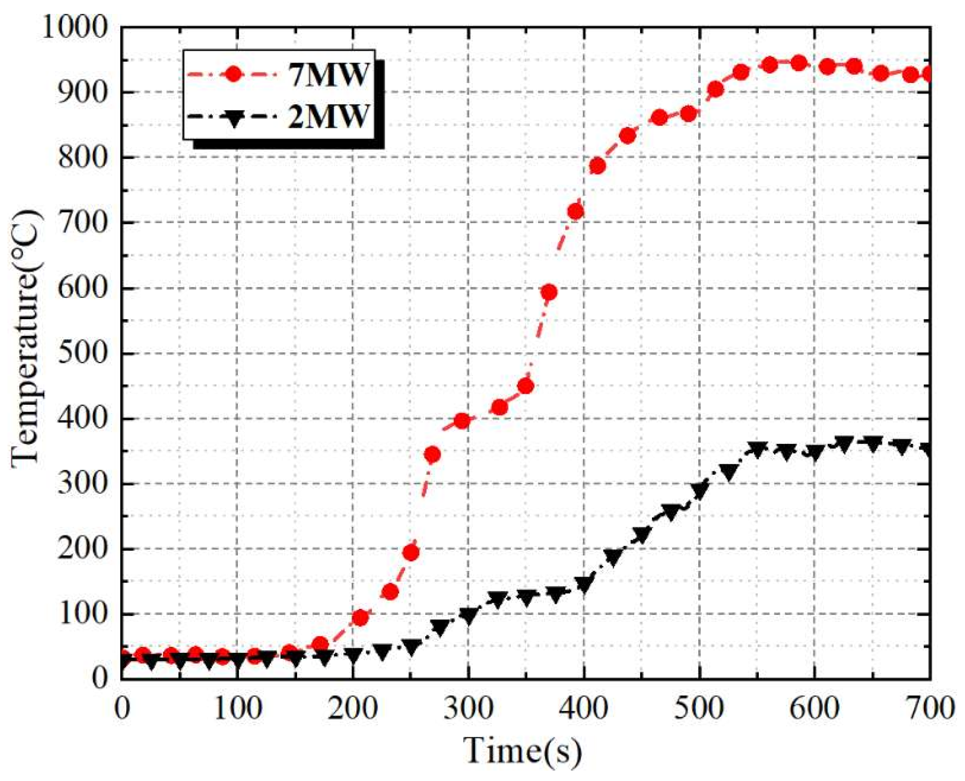
The discharge power and cut-off time are used as the ignition power and ignition time of cable combustion, respectively, to simulate the combustion process under two different ignition conditions. The fire may continue to increase, and other protection will be started when the fire time is too long, which is not considered in this test. Hence, the burning time of the fireproof clapboard is not too long, and the fire prevention effect is about 10 min. Thermocouples are used to monitor the 10 min temperature rise trend and data for the test of the fireproof clapboard, as plotted in Figure 7.
When the temperature rises slowly to about 50 °C, the ignition exhaust is removed. Then, the intermediate joint of the cable began to spontaneously ignite. Within 120 s, the molten material dripped and continued to burn, and the temperature rise curve increased significantly. When the ventilation flow rate is 2.1 kJ, the temperature reaches 40 °C, and the rising trend slowed down after 140 s of the test. Then, it gradually reached a stable maximum temperature of about 354 °C. At a ventilation flow rate of 4.9 kJ, the melt began to drip off in large quantities after about 50 s, and the fire suddenly increased with the temperature rising to 935 °C within 10 min. Then, most parts of the cable intermediate joints are ignited, and the fire temperature reaches 948 °C without change.

2.3. Selection of Fire Source Power for Fireproof Clapboard Combustion Testing

The actual experiment of cable self-combustion has many problems. For example, it is difficult to control the combustion of the cable. The smoke produced by the combustion is more polluted, and the test cable has a low reuse rate and high cost. Therefore, unlike the cable self-combustion test, clean fuel is used instead of cable for combustion in the testing. The corresponding fuel heat release rate (the fire source power of cable combustion) is determined by being combined with the thermal power change data and the calorific value of fuel combustion. The fuel combustion is controlled by the flow control unit to simulate the fire environment of the cable tunnel and detect the fireproof clapboard products. The method can improve the operability of the test and make the combustion power controllable, and it can reduce the cost and meet the requirements of a green environmental protection test.
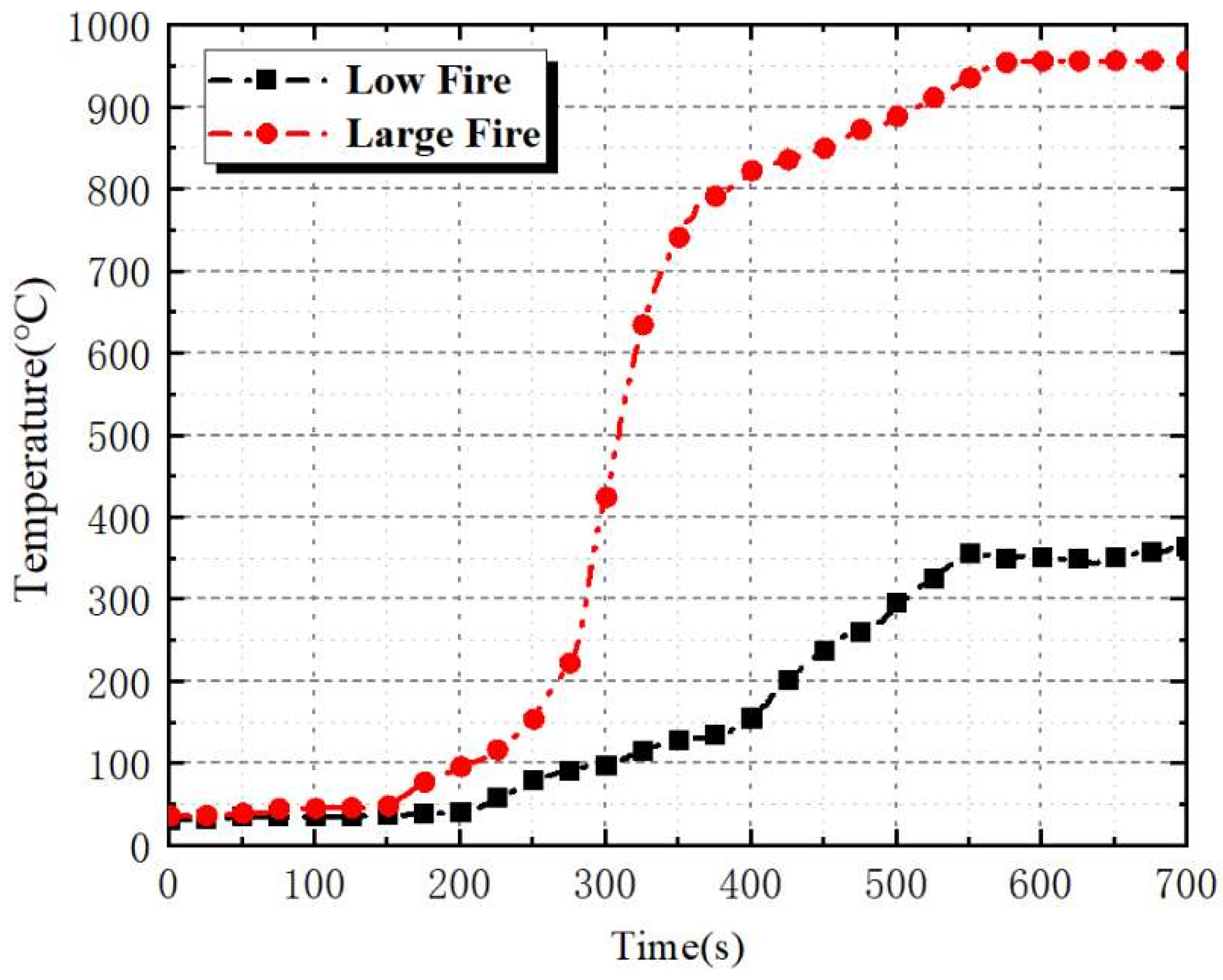
The device controls the temperature rise trend of the fire source by controlling the combustion of clean fuel, as shown in Figure 3. The combustion temperature rise curve of clean fuel under two working conditions is shown in Figure 8. The maximum combustion temperature is about 350 °C after the low fire is stabilized, and the maximum combustion temperature is about 950 °C after the large fire is stabilized. The test results show that the method of using clean energy combustion makes the combustion temperature rise curve smooth and can be controlled at any time, which is conducive to the test of the fireproof clapboard. It can be calculated that the power calculated by the calorific value of the fire source for propane gas combustion is about 200–400 kW. The firepower of 200 kW, 300 kW, and 400 kW is taken as three levels to test the fireproof clapboard in the range of allowable error of 10% to reduce the difference of different combustion and analyze the partition under various working conditions.

3. Analysis of the Fire-Resistant Property of Different Materials of Fireproof Clapboards

Four kinds of fireproof clapboards with a size of 2.0 m × 0.4 m and a thickness of 10 mm are used in the cable tunnel in the test. Three boards are prepared for each material fireproof clapboard, and the fire prevention effect test is carried out under three fire source powers.

3.1. Test Method

The fire source power of 200 kW, 300 kW, and 400 kW is set to complete the fire prevention effect test of temperature change and mechanical deformation of four kinds of clapboards (the inorganic glass-magnesium board, the inorganic calcium silicate board, the organic pultruded board, and the organic molded board) under different fire conditions (mild, moderate, and severe fire conditions). The temperature measurement points on the three temperature-sensing optical fibers on the inner, middle, and outer sides of the protective surface of the fireproof clapboard are compared. The temperature measurement point with the highest temperature is selected.
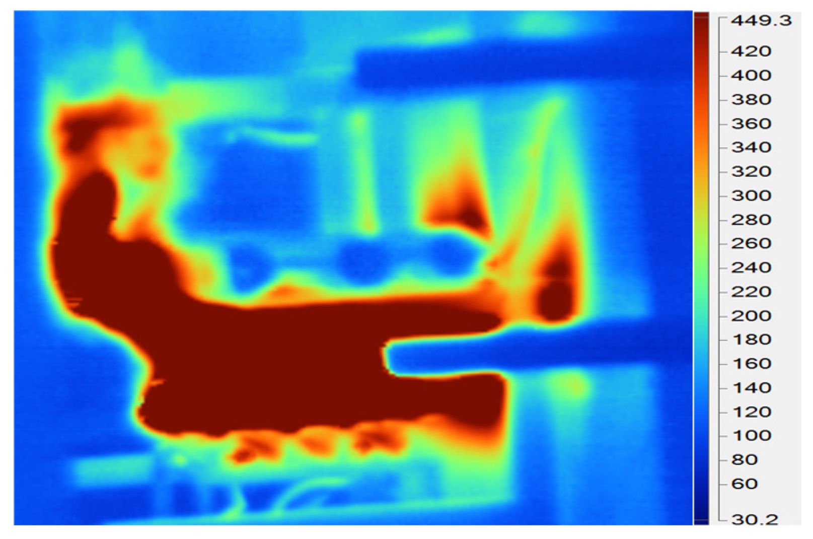
According to ISO 834-1-1999 [24], the temperature rise at any position of the specimen exceeds the initial temperature of 180 °C, and the specimen is recognized to lose thermal insulation. However, the fireproof clapboard that meets the building standard burns and deforms before the fire source temperature reaches 180 °C in the cable tunnel fire experiment. Therefore, this standard cannot be used as a standard for fireproof clapboards in cable tunnel fires. The tolerance temperature of the cable outer sheath is used as a reference in the analysis of the thermal insulation effect of the fireproof clapboard. Hence, it lacks the damage temperature of the cable outer sheath and does not meet the actual test conditions. Ma et al. [25] found that the damage temperature of outer sheath PVC is 120 °C through this study of PVC chemical substances. The experimental verification of the temperature tolerance of the outer sheath of the fireproof clapboard is shown in Figure 9. The temperature distribution of the outer sheath is measured by the infrared thermal imager, as shown in Figure 10. The result shows that the outer sheath is damaged when the temperature reaches 120–130 °C. In the range of allowable error of 10%, the temperature of the protective surface is controlled below 120 °C, and the temperature of the protective surface and the fire surface of the fireproof clapboard is compared. The heat insulation effect, combustion performance, and mechanical properties of the four kinds of fireproof clapboards are further analyzed.

3.2. The Temperature of the Characteristic Points of the Protective Surface of the Fireproof Clapboard

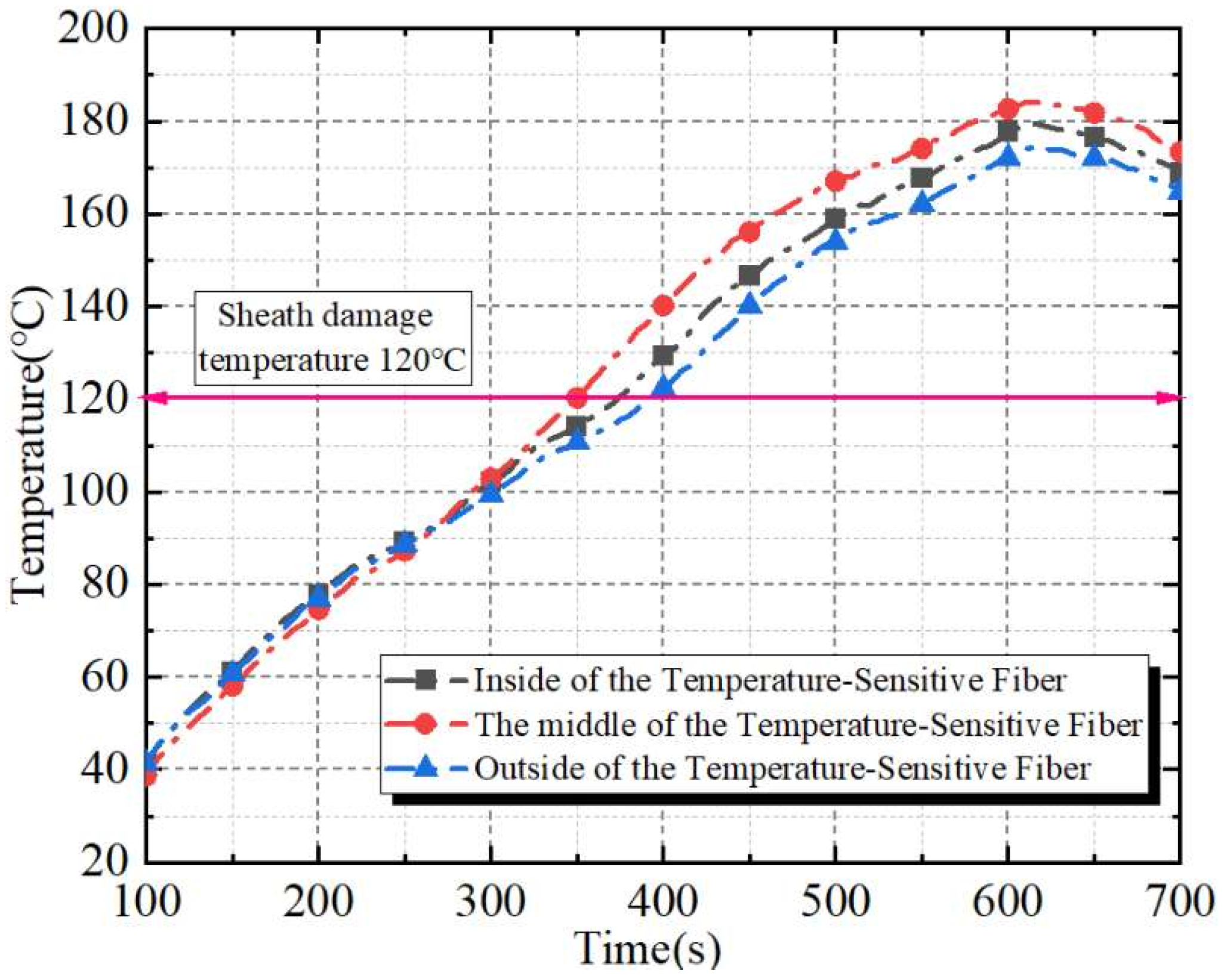
The inorganic glass-magnesium board is used to measure the temperature curves of three temperature-sensitive optical fibers on the protective surface of the clapboard under 400 kW fire source power, as shown in Figure 11. The results show that the temperature of the intermediate optical fiber in the board is higher than that of the inner and outer sides of the board. The temperature of the intermediate optical fiber above the fire source is about 30 °C higher than that on both sides of the board and reaches 120 °C in 250 s. Hence, the intermediate temperature-sensitive optical fiber is the highest temperature measurement point. When the protective surface of the clapboard reaches 120 °C, it can be considered that the cable sheath heat insulation are damaged. Thus, the test should be stopped.

3.3. Analysis of the Fire Resistant Effect of Each Material Clapboard

Based on the above test methods and analysis, the above combustion tests were carried out on these four typical fireproof clapboards. The temperature rise of the clapboards under each fire source power was monitored to analyze their combustion performance. In addition, the mechanical deformation of the clapboard was observed, and whether it can carry cables was analyzed. Combined with the bearing capacity and combustion performance of the clapboard, it is optimized.
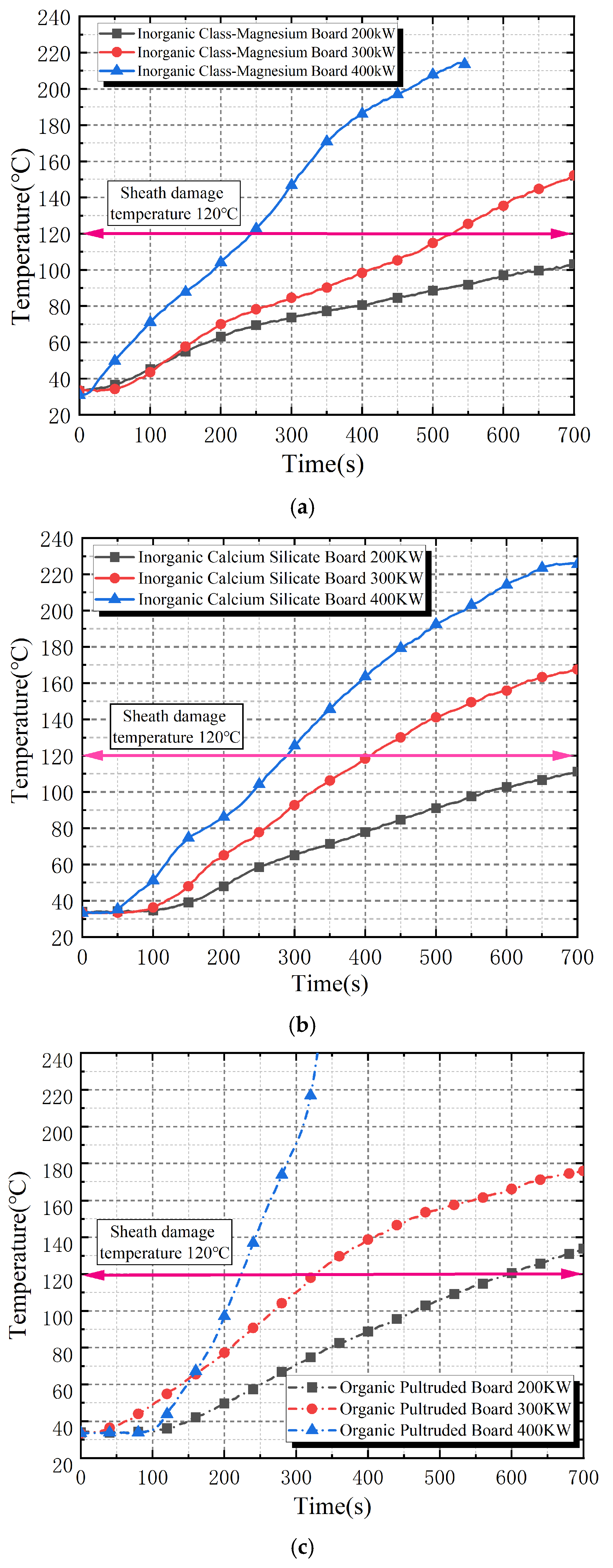
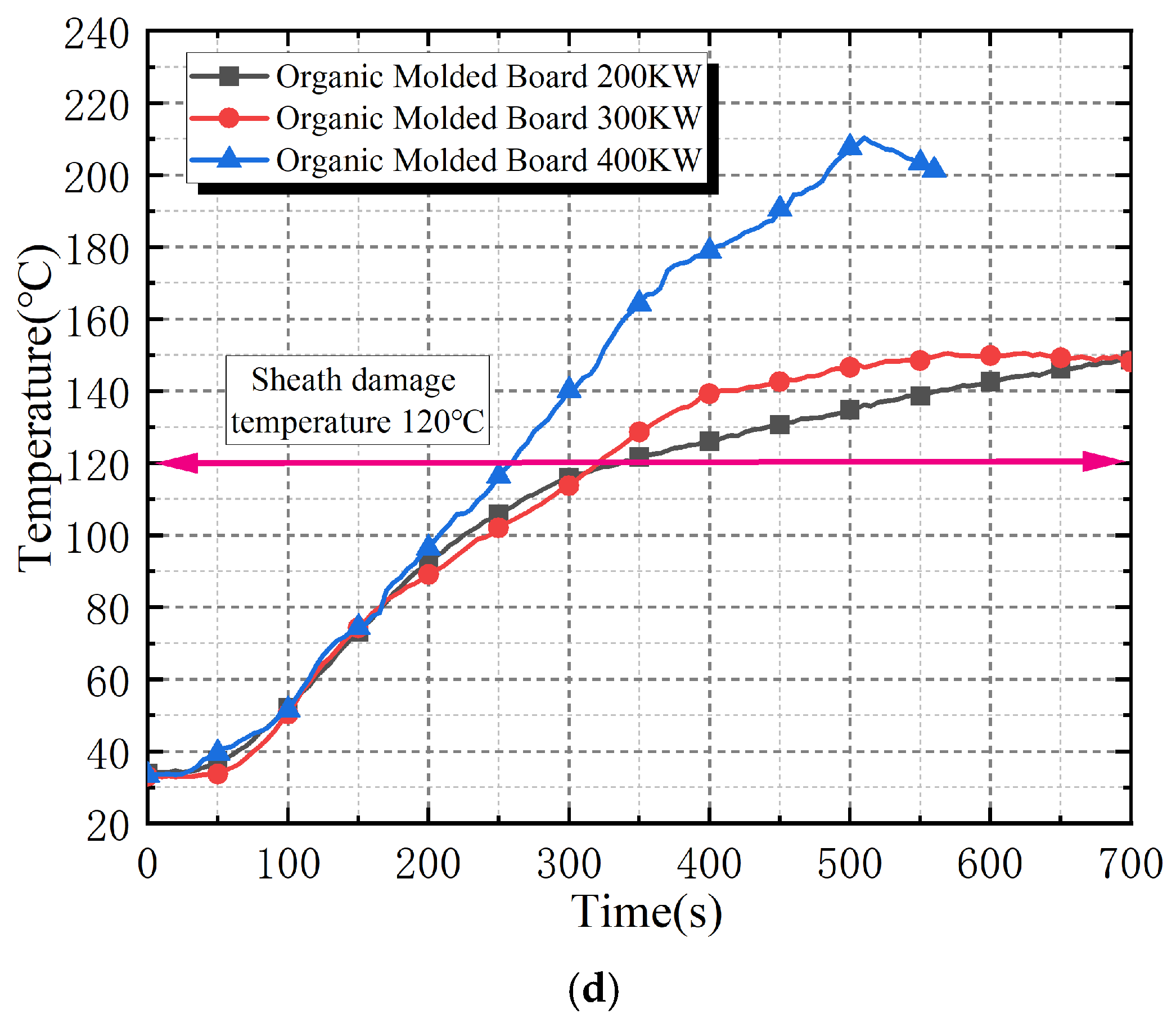
The temperature rise curves of the four fireproof clapboards under three fire source powers are shown in Figure 12. The results show that the higher the fire power, the faster the combustion separator reaches the cable outer sheath damage temperature of 120 °C, and the worse the thermal insulation performance. The organic clapboards are non-combustible materials. The heat resistance of the inorganic glass magnesium board and the inorganic calcium silicate board is strong. Therefore, the effective heat insulation time of the inorganic board is longer than that of the organic board at the same power. However, the protection time of the cable outer sheath by the organic molded board at 400 kW fire power is about 15.6% longer than that of the organic pultruded board.
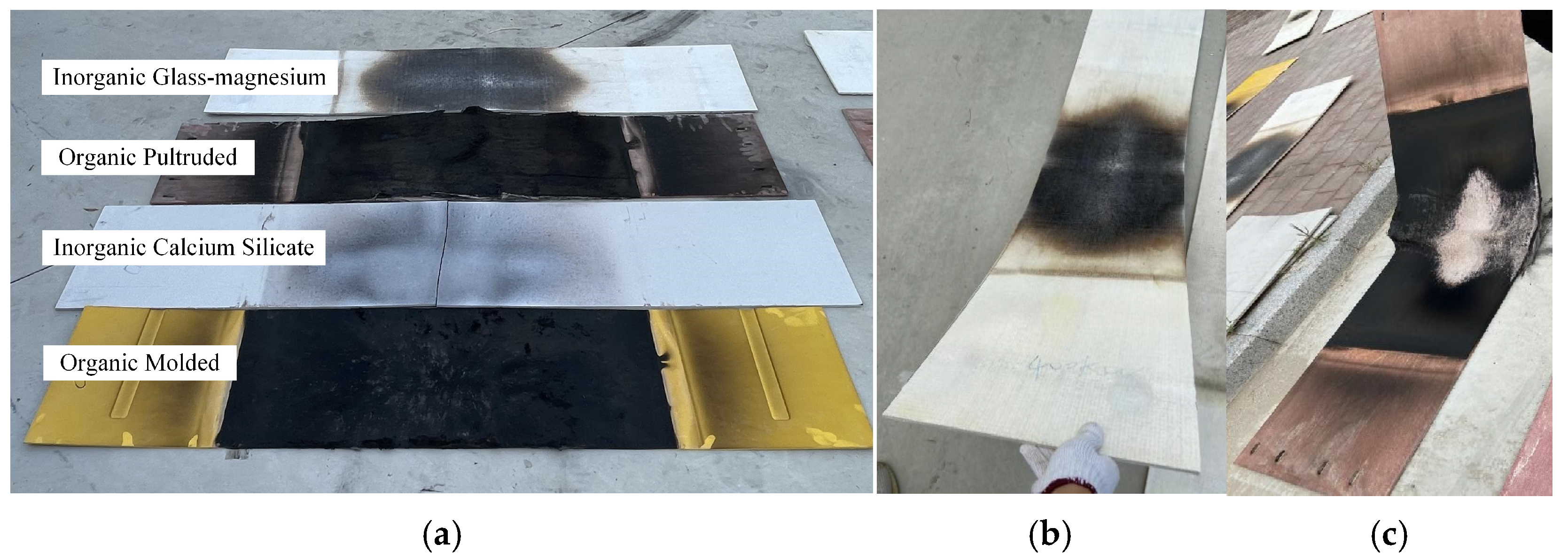
The bearing capacity combustion test of the clapboard was carried out at 200 kW, 300 kW, and 400 kW, respectively. The 400 kW fire source power is a serious fire. It is close to the actual cable tunnel fire accident. The combustion results of the four clapboards at 400 kW fire source power are shown in Figure 13. The results show as follows:
The mechanical properties of the inorganic calcium silicate board are the lowest among the four clapboards. The middle of this clapboard is directly broken and loses fire resistance. The inorganic glass magnesium board is bent and has poor fire resistance, as shown in Figure 13b. The reason is that the inorganic boards composed of amorphous phase, glass fiber, and organic polymer are the non-combustible material. Under the high temperature change, dislocation slip occurs inside the grains, which is macroscopically realized as plastic deformation. At the same time, the exposed glass fiber and organic polymer after combustion produce viscous flow, which is macroscopically realized as viscous deformation. Both of these deformations are irreversible permanent deformations that eventually lead to bending fractures.
The organic board is made of resin and glass fiber. The resin has the advantages of good dimensional stability after curing, high mechanical strength, excellent electrical insulation, and heat resistance, but it has the problems of brittleness, low toughness, and easy fatigue aging [26]. The organic pultruded board exposes the glass fiber after the resin is burned out, and the glass fiber is carbonized under the action of waste heat, resulting in different degrees of damage to the organic pultruded board under different firepower. Therefore, the organic pultruded plate after combustion exhibits a bending phenomenon as shown in Figure 13c. However, the addition of aluminum hydroxide to the material composition of the organic molded board makes the molding uniformity of the fireproof clapboard good, and the degree of damage is lower than that of the organic pultruded board. In addition, there are a large number of hydrophilic groups in the resin, which makes the glass fiber prone to pyrolysis and combustion at high temperatures [27]. After burning, the organic molded board will produce scales of calcium carbonate, magnesium carbonate, and other components. The black carbonized material is attached to the surface of the damaged board. After combustion, the phenomenon is shown in Figure 13a. Therefore, the organic molded board shows the best combustion-bearing capacity and fire prevention effect.
Combined with the above analysis of the combustion performance and bearing capacity of the four clapboards. Although the fire resistance of the inorganic clapboard is better than that of the organic clapboard, the high temperature during combustion causes irreversible deformation of the material composition of the inorganic clapboard. The inorganic glass magnesium board becomes soft and bent, and the inorganic calcium silicate board directly breaks. Therefore, the inorganic clapboards are impossible to bear the weight of the cable in severe fires and cannot effectively defend the cable tunnel fire. However, the organic molded board can not only effectively protect the cable fire, but also the material is uniform and not easy to soften and break. Comprehensive analysis shows that the organic molded board shows the best fire-resistance property.

4. Analysis of Structure and Configuration of Fireproof Clapboard

The cable sheath may still be pyrolyzed under the condition of cable fire protection product configuration in the middle joint area of the existing high-voltage cable tunnel in the case of severe fire. The fire insulation effect test of different L-shaped fireproof clapboard side plate heights, different fireproof clapboard thicknesses, and different fireproof clapboard installation methods was carried out. The fire-resistant effect of the fireproof clapboard is compared and analyzed. The organic molded board was used for research to obtain the corresponding configuration parameters based on the above experimental analysis.

4.1. The Influence of the Thickness of the Board on Protective Performance

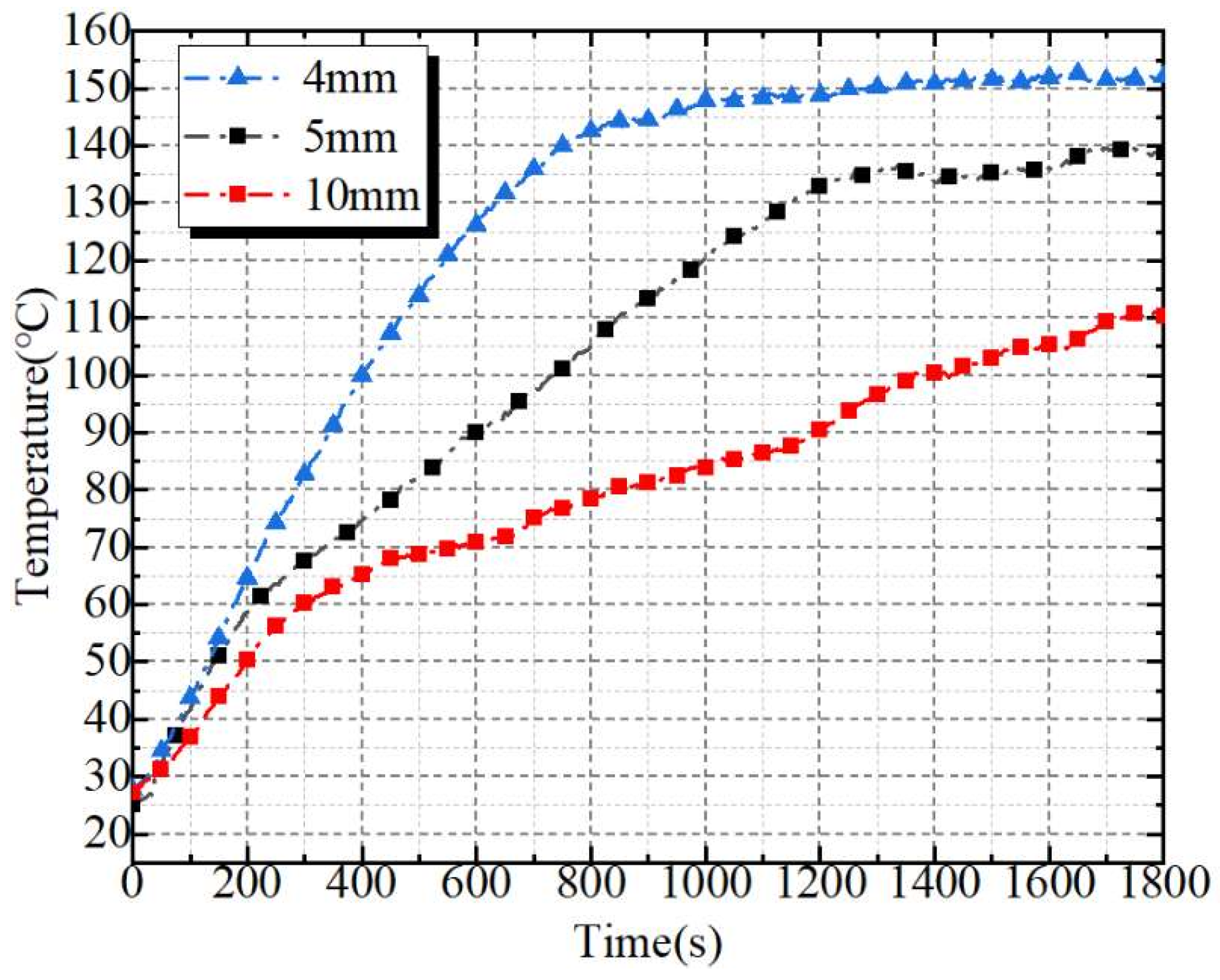
The cable outer sheath material begins to pyrolyze when it is greater than 120–165 °C. According to the cable fire risk judgment standard [28] and the cable damage during the pretest, the critical temperature of the cable outer sheath pyrolysis damage is set to 120 °C. At 200 kW firepower, the cable sheath temperature on the three different thicknesses of the organic molded board is shown in Figure 14. The cable above the 4 mm thick clapboard reaches the pyrolysis temperature after 545 s, and the maximum temperature reaches 150 °C. At this time, the situation tends to be stable. The cable above the 5 mm thick clapboard reaches the pyrolysis temperature after 995 s, and the maximum temperature reaches 140 °C. At this time, the situation tends to be stable. The maximum temperature of the cable above the 10 mm thick clapboard is stable after reaching 110 °C after 1730 s.
The rise rate of the cable above the 4 and 5 mm diaphragms is roughly the same in 200 s, and the later rise rate begins to appear as an obvious difference. The temperature rise rate of the cable sheath above the 5 mm diaphragm is slowed down, and the temperature rise rate of the cable above the 10 mm diaphragm is much lower than that of the 4 mm and 5 mm diaphragms. The thicker the fireproof clapboard, the longer the solid heat conduction time under slight fires. The slower the temperature rise of the protective surface of the fireproof clapboard, the better the fire insulation effect and the longer the effective protection time for the cable outer sheath. However, the fire lasts for about 10 min in the actual cable tunnel fire, which will trigger other protective actions such as fire extinguishing bombs. Considering the cost, in response to the requirements of economic, green, and environmental protection, the 5 mm thick fireproof clapboard that has a good fire insulation effect is selected.

4.2. The Influence of Side Plate Height on the Protective Performancer

The test cable is 110 kV with a length of 1.5 m and a diameter of 12 cm. It is found that the cable on the upper bracket of the fire source is ignited within 5 s in the case of no fireproof clapboard. The clapboard with side plate was tested under different fire source power. When the fire source power is 200 kW, the flame height is low, just touching the bottom of the fireproof clapboard. The cable on the fireproof clapboard is protected from the direct burning of the flame and the hot air flow. Through heat conduction, the temperature of the cable sheath on the fireproof clapboard increases gradually and reaches the pyrolysis temperature of the sheath after about 980 s. Finally, the temperature tends to be stable at about 140 °C. The temperature rises faster when the firepower increases. When the power of the fire source is 400 kW, the flame height is further increased. The fire plume quickly envelopes the side of the fireproof clapboard, and the hot gas flows upward after contacting the fireproof clapboard. Under the combined action of the hot gas flow and the flame, the temperature rise rate of the cable is further increased. After about 550 s, the sheath pyrolysis temperature is reached, which is 43% faster than that at 200 kW. Then, after the combustion is stable, the final temperature tends to 194 °C.
Therefore, the fireproof clapboard can effectively prevent the fire from spreading to the upper layer. The fire is more concentrated on the underlying fire cable, thereby prolonging the protection time of the cable above it. However, the flame blocked by the clapboard will also bypass the side plate to form an enveloped fire plume when the fire increases. Some of the flame inclusions will directly act on the outer sheath of the cable, resulting in rapid pyrolysis damage to the sheath. It is necessary to install an L-shaped side plate on the fireproof clapboard to improve the protection effect. The outer sheath protection time of different side plate heights is shown in Table 2.
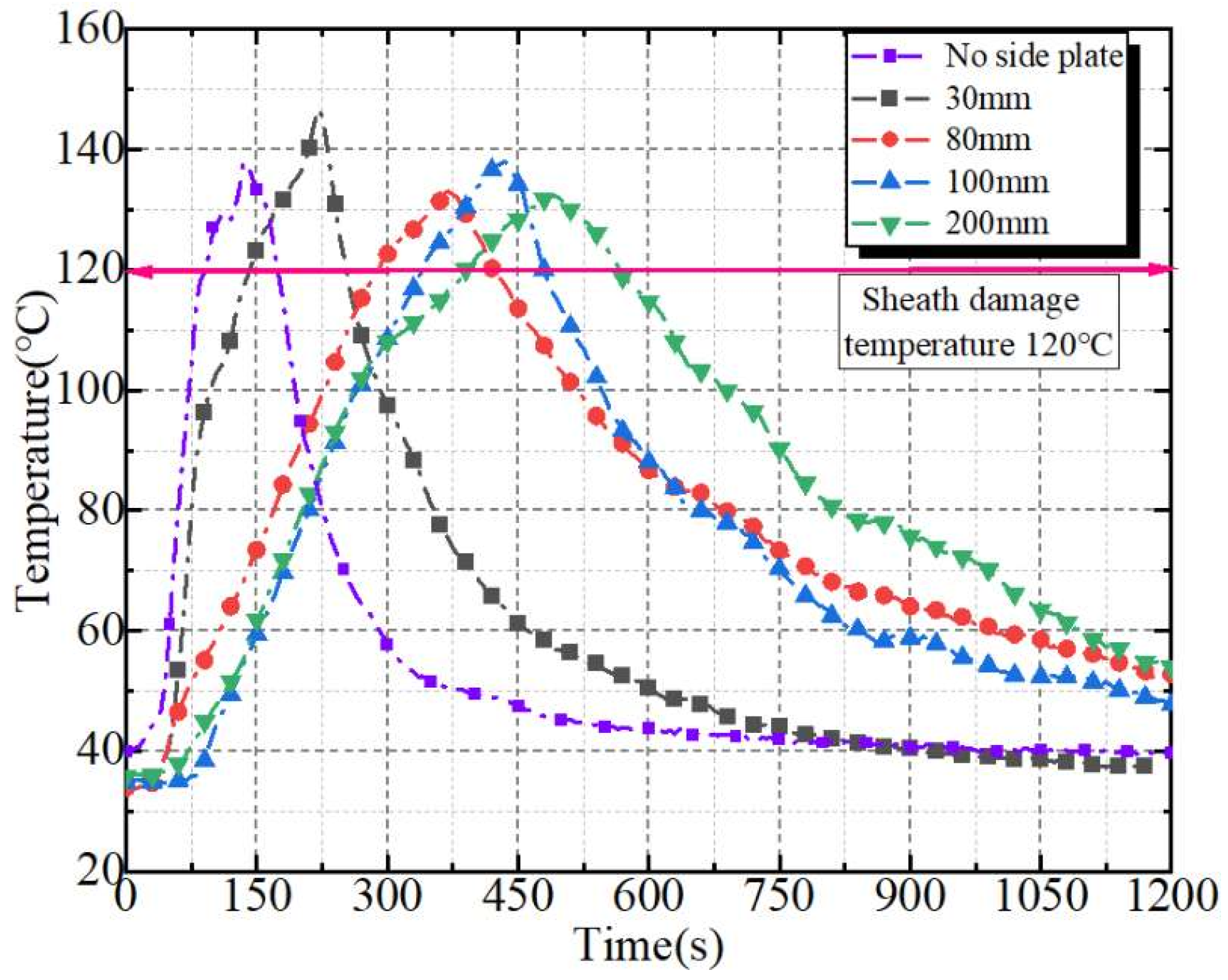
Under the condition of side plate height of 0–200 mm, the fastest pyrolysis time of cable sheath is 90 s, and the slowest is 390 s. The test process is shown in Figure 15. The temperature of fireproof clapboards with different side plate heights is shown in Figure 16. The fireproof clapboard with a side plate can prolong the protection time of the cable outer sheath compared with the fireproof clapboard without a side plate. Among them, the L-shaped fireproof clapboard with a side plate height of 200 mm has the longest protection time, which is extended by about 333%. Thus, the L-shaped fireproof clapboard can effectively prevent the upper cable from being ignited. The fire will form an enveloped fire along the side plate of the fireproof clapboard after being blocked by the board.
However, the diameter of the 110 kV cable is 120 mm. The envelope flame blocked by the baffle acts on the cable sheath, and the sheath accelerates the pyrolysis when the height of the side plate is lower than 120 mm. The enveloped fire current cannot act directly on the cable outer sheath quickly when the height of the side plate is higher than 120 mm. Then, the protection time of the cable is prolonged. The L-shaped fireproof clapboard has a side plate, and the height of the side plate is higher than the cable diameter. The higher the height, the longer the protection time of the cable. Therefore, the side plate height of up to 200 mm can effectively protect the cable.

4.3. Comparative Analysis of Hoisting and Flat Installation Methods

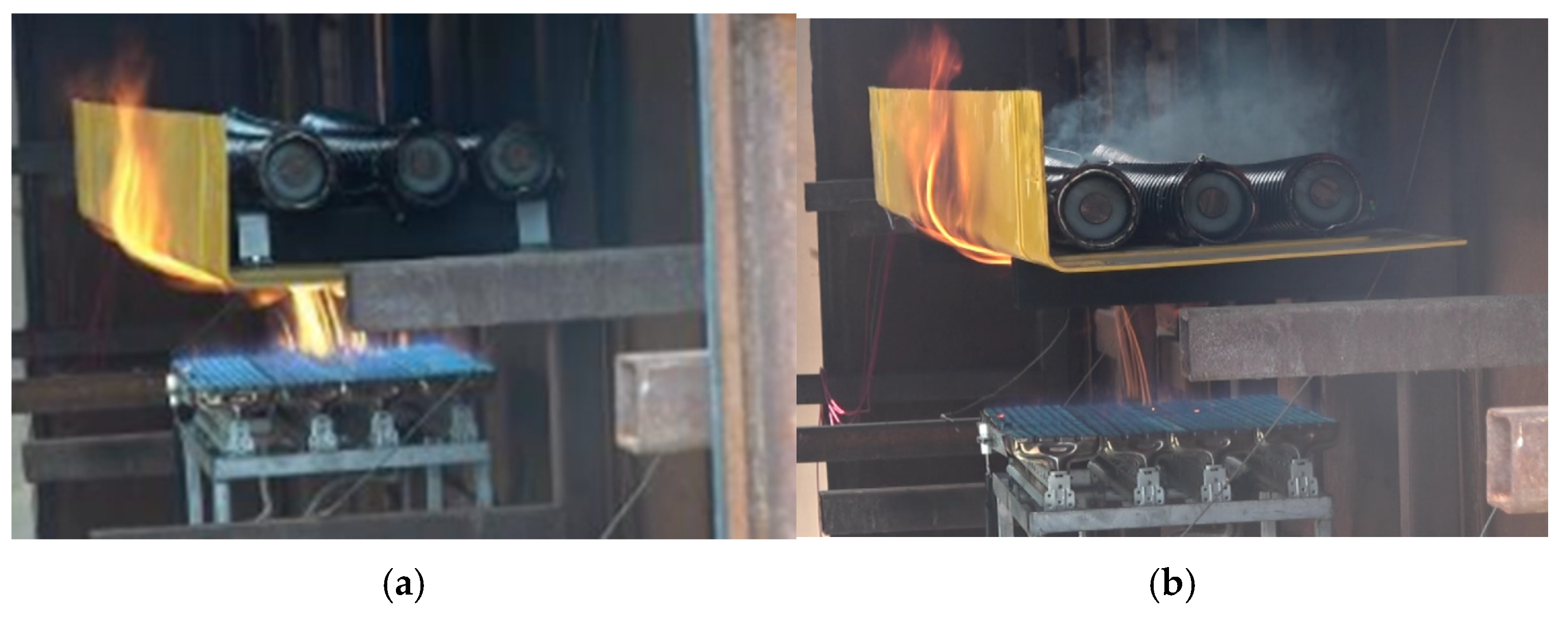
The L-shaped fireproof clapboard with a side plate height of 200 mm is selected, as shown in Figure 17. The fire insulation effect test of the fireproof clapboard on the bracket above the fire source is carried out under the two installation methods of hoisting installation and flat installation methods. Different installation methods of the outer sheath pyrolysis temperature time are shown in Table 3. When the hoisting installation method is adopted in Figure 17a, the bottom of the cable will be 60 mm away from the clapboard to test the influence of different installation methods of the fireproof clapboard on the temperature of the cable outer sheath after the cable fire. When the fire source power is 200 kW and 400 kW, respectively, the time for the cable sheath on the hoisting clapboard to reach the pyrolysis temperature is 1370 s and 615 s, respectively, as shown in Table 3. Compared with the flat installation method of the clapboard in Figure 17b, the protection time is extended by about 38% and 15%, respectively. With the increase of fire source power, the temperature rise rate of the cable outer sheath in hoisting mode is slower than that in tiled mode. When the cable outer sheath reaches the pyrolysis temperature of 120 °C after 320 s in the flat installation mode, the cable outer sheath reaches 120 °C after 425 s in the hoisting installation mode. Thus, the cable protection time can be extended by about 33% when the fireproof clapboard is hoisted. When the fireproof clapboard is flat on the cable tunnel bracket, the bottom of the cable is in direct contact with the fireproof clapboard. Smoke appears after the outer sheath is overheated due to the high temperature at the bottom of the fireproof clapboard after the fire occurs. The hoisting method avoids the direct contact between the cable and the fireproof clapboard, which prolongs the time to reach the pyrolysis temperature. Therefore, the hoisting method is recommended when installing the fireproof clapboard, and the effective protection time is longer.

5. Conclusions

Based on the equivalent fire source condition of cable fire, the fire resistance test of fireproof clapboards with different materials, structures, and installation methods is carried out. By comparing the protective performance, the following conclusions are obtained:
(1)
The temperature rise characteristics of the developed equivalent fire source are within 10% of the allowable error of the actual cable combustion. Based on the combustion of typical cable intermediate joints, three kinds of fire source with maximum combustion power of 200 kW, 300 kW, and 400 kW are set up to test the protective performance of the fireproof clapboard applied in the cable tunnel.
(2)
The test results of fireproof clapboards of different materials show that although the inorganic glass-magnesium board and inorganic calcium silicate board have stronger heat resistance, they cannot bear the weight of the cable. Eventually these two types of clapboards break. However, the organic molded board can not only effectively protect the cable fire, but also the material is uniform and not easy to soften and break. Based on the analysis of combustion performance and bearing capacity, the organic molded board shows the best fire-resistant property.
(3)
To achieve effective fire protection, it is recommended that the thickness of the fireproof clapboard should reach 5 mm. Compared with the case where the fireproof clapboard has no side plate under severe fire, the protection time of the L-shaped fireproof clapboard with side plate heights of 30 mm, 80 mm, 100 mm, and 200 mm to the cable outer sheath is prolonged by about 56%, 222%, 277%, and 333%, respectively. And high-voltage cables above 110 kV need the side plate height to be 200 mm. In addition, the effective protection time of the hoisting method can be extended by about 30% compared with the flatting method, and the hoisting method is preferred when the interlayer space is satisfied.

Author Contributions

Writing—review and editing, H.J. and H.L.; Writing—original draft, J.C. and W.G.; Data curation, Z.R., Z.P. and Y.M. All authors have read and agreed to the published version of the manuscript.

Funding

This study was supported by the State Grid Beijing Electric Power Company Technology Project (520223230013).

Institutional Review Board Statement

Not applicable.

Informed Consent Statement

Not applicable.

Data Availability Statement

The original contributions presented in this study are included in the article; further inquiries can be directed to the corresponding author.

Conflicts of Interest

This research was conducted in the absence of any commercial or financial relationships that could be construed as potential conflicts of interest.

References

  1. Liang, K.; Hao, X.; An, W.; Tang, Y.; Cong, Y. Study on cable fire spread and smoke temperature distribution in T-shaped utility tunnel. Case Stud. Therm. Eng. 2019, 14, 14100433. [Google Scholar] [CrossRef]
  2. An, W.G.; Wang, T.; Liang, K.; Tang, Y.H.; Wang, Z. Effects of interlayer distance and cable spacing on flame characteristics and fire hazard of multilayer cables in utility tunnel. Case Stud. Therm. Eng. 2020, 22, 100784. [Google Scholar] [CrossRef]
  3. Guo, D.; Wang, J.; Li, S.; Shi, C.; Zhou, Y.; Li, P.; An, X.; Xiong, Y. Numerical study on smoke temperature and exhaust efficiency in electric cable tunnel. J. Phys. Conf. Ser. 2024, 2728, 012010. [Google Scholar] [CrossRef]
  4. Zheng, X.Z.; Cai, G.B.; Guo, J.; Gao, W.J.; Huang, Y.; Tong, X. Combustion characteristics and thermal decomposition mechanism of the flame-retardant cable in urban utility tunnel. Case Stud. Therm. Eng. 2023, 44, 102887. [Google Scholar] [CrossRef]
  5. Nan, H.; Nedar, E.K.; Anthony, T.; Ravi, R. Experimental study of fire damage to reinforced concrete tunnel slabs. Fire Saf. J. 2022, 127, 103504. [Google Scholar]
  6. Wang, S.; Zhu, K.; Yao, Z.; Zhao, S.; Chen, Y.; Song, Z. Study on Combination Scheme of Cable Laying and Fire Prevention Measures in High Voltage Cable Trench. In Proceedings of the 2021 International Conference on Advanced Electrical Equipment and Reliable Operation (AEERO), Beijing, China, 15–17 October 2021; pp. 1–5. [Google Scholar]
  7. Takeuchi, S.; Aoki, T.; Tanaka, F.; Moinuddin, K.A. Modeling for predicting the temperature distribution of smoke during a fire in an underground road tunnel with vertical shafts. Fire Saf. J. 2017, 91, 312–319. [Google Scholar] [CrossRef]
  8. Gao, Z.H.; Wan, J.J.; Zhu, J.P.; Sun, J.H. Experimental investigation on transverse ceiling flame length and temperature distribution of sidewall confined tunnel fire. Fire Saf. J. 2017, 91, 371–379. [Google Scholar] [CrossRef]
  9. Dai, W.T. Study on the fire detection and alarm of cable tunnel and integrated pipe gallery. Fire Sci. Technol. 2017, 36, 89–92. [Google Scholar]
  10. Zhang, A.F. Research on Fire Door Linkage Strategy Based on Distributed Optical Fiber Temperature Measurement System. Ph.D. Thesis, Chongqing University of Technology, Chongqing, China, 2022. [Google Scholar] [CrossRef]
  11. An, W.G.; Wang, X.S.; Tang, Y.H.; Lu, J.T. Influence of cable inclination angle and longitudinal ventilation on temperature distribution during cable fire in utility tunnel. Case Stud. Therm. Eng. 2021, 27, 101304. [Google Scholar] [CrossRef]
  12. Liu, X.S.; Hou, D.; Ji, J.; Zhu, H. Experiment and numerical simulation of cable trench fire detection. Case Stud. Therm. Eng. 2021, 28, 101338. [Google Scholar] [CrossRef]
  13. Ding, B.; Nie, X.; Lv, X.; Zhou, Y.; Su, Y.; Yang, H. Simulation of Fire Spread in Cable Tunnel with Different Fire Barriers. In Proceedings of the 2021 International Conference on Advanced Electrical Equipment and Reliable Operation (AEERO), Beijing, China, 15–17 October 2021; pp. 1–4. [Google Scholar]
  14. Pu, Z.; He, J.; Guo, W.; Zhou, S. Heat insulation effect analysis and side panel height design of L-shaped fire baffle in cable tunnel. Fire Sci. Technol. 2022, 41, 615–620. [Google Scholar]
  15. Wang, M.N.; Tian, Y.; Yu, L.; Yan, Z.H.; Jin, W. Numerical simulation and influencing factors analysis of cable fire in urban utility tunnel. J. Saf. Sci. Technol. 2018, 14, 52–57. [Google Scholar]
  16. Li, C.Y.; Chen, J.; Chen, H.; Tan, X.; Liu, K.; Xie, Q.Y. Effects of ventilation through the top vent on smoke movement in high voltage cable tunnel. Fire Sci. Technol. 2019, 38, 476–478. [Google Scholar]
  17. Zhang, J.-Q.; Fan, M.-H.; Li, W.; Wang, L.-F.; Wu, H.-C.; Wang, S.-P. Research on Mechanical Ventilation Protection Technology of Power Cable Tunnel. Electr. Power 2017, 50, 113–119. [Google Scholar]
  18. NFPA 204; Standard for Smoke and Heat Venting. National Fire Protection Association: Quincy, MA, USA, 2018.
  19. United States Nuclear Regulatory Commission. Cable Heat Release, Ignition, and Spread in Tray Installations During Fire Phase 1: Horizontal Trays; United States Nuclear Regulatory Commission: Washington, DC, USA, 2012. [Google Scholar]
  20. United States Nuclear Regulatory Commission. Fire PRA Methodology for Nuclear Power Facilities, NUREG/CR-6850; United States Nuclear Regulatory Commission: Washington, DC, USA, 2004. [Google Scholar]
  21. Kizilcay, M.; Koch, K.-H. Numerical fault arc simulation based on power arc tests. Eur. Trans. Electr. Power 2007, 4, 177–185. [Google Scholar] [CrossRef]
  22. Liang, X.-H. Probabilistic Insecurity Index Considering the Effect of Fault Cleaning Time. Master’s Thesis, Tianjin University, Tianjin, China, 2007. [Google Scholar]
  23. IEC 60695-2-11-2021; Fire Hazard Testing—Part 2-11: Glowing/Hot-Wire Based Test Methods—Glow-Wire Flammability Test Method for End Products (GWEPT). ISO: Geneva, Switzerland, 2021.
  24. ISO 834-1-1999; Fire-Resistance Tests—Elements of Building Construction—Part 1:General Requirements. International Organization for Standardization: Geneva, Switzerland, 1999.
  25. Ma, S.-C. Chemical Substance Dictionary. Master Thesis, Shaanxi Science and Technology Press, Xi’an, China, 1999. [Google Scholar]
  26. Zhang, X. Study on the characterisitics of epoxy resin and its application as a functional building material. Appl. Chem. Ind. 2022, 51, 884–886+890. [Google Scholar]
  27. An, W.; Tang, Y.; Liang, K.; Wang, T.; Zhou, Y.; Wen, Z. Experimental Study on Flammability and Flame Spread Characteristics of Polyvinyl Chloride (PVC) Cable. Polymers 2020, 12, 2789. [Google Scholar] [CrossRef] [PubMed]
  28. ISO 13943:2000; Fire Safety-Vocabulary. ISO: Geneva, Switzerland, 2000.
Figure 1. The real combustion chamber.
Fire 07 00357 g001
Figure 2. Combustion simulation platform.
Fire 07 00357 g002
Figure 3. Test equipment device.
Fire 07 00357 g003
Figure 4. Arrangement of thermocouples on fire-facing surface of fireproof clapboard.
Fire 07 00357 g004
Figure 5. Arrangement of temperature-sensitive optical fiber on the protective surface of fireproof clapboard.
Fire 07 00357 g005
Figure 6. Self-combustion process of cable intermediate join: (a) Ignition; (b) Initial combustion; (c) Catch fire; (d) Mid-combustion; (e) Post flame; (f) End of combustion.
Fire 07 00357 g006
Figure 7. Temperature rise curves under different ignition conditions.
Fire 07 00357 g007
Figure 8. The combustion temperature rise curve of clean fuel under two working conditions.
Fire 07 00357 g008
Figure 9. Experiment on temperature tolerance of outer sheath of fireproof clapboard.
Fire 07 00357 g009
Figure 10. Pyrolysis temperature distribution of outer sheath.
Fire 07 00357 g010
Figure 11. The temperature curve of the characteristic points on the protective surface of the fireproof clapboard under 400 kW fire source power.
Fire 07 00357 g011
Figure 12. The temperature rise curves of four kinds of clapboards under three fire source power. (a) The inorganic glass-magnesium board under different fire source power; (b)The inorganic calcium silicate board under different fire source power; (c) The organic pultruded board under different fire source power; (d) The organic molded board under different fire source power.
Fire 07 00357 g012aFire 07 00357 g012b
Figure 13. The change of bearing capacity in clapboards after combustion. (a) The combustion experimental diagram of each clapboard under 400 kW fire source power; (b) The Inorganic Glass-Magnesium Board; (c) The Organic Pultruded Board.
Fire 07 00357 g013
Figure 14. Cable sheath temperature on different thickness clapboards.
Fire 07 00357 g014
Figure 15. The test process diagram of fireproof clapboard with different side plate heights. (a) No side plate; (b) 30 mm; (c) 80 mm; (d) 100 mm; (e) 200 mm.
Fire 07 00357 g015
Figure 16. The temperature of fireproof clapboards with different side plate heights.
Fire 07 00357 g016
Figure 17. Schematic diagram of two installation methods of fireproof clapboard. (a) Hoisting installation method; (b) Flat installation method.
Fire 07 00357 g017
Table 1. Combustion Data Sheet.
Short-term power2 MW7 MW
Firing time0.7 s0.7 s
Total combustion energy1.4 MJ4.9 MJ
Actual ignition power140 kW490 kW
Initialization time10 s10 s
Propane ventilation flow3.02 g/s10.56 g/s
Table 2. Different side plate height protection data.
Side plate height0 mm30 mm80 mm100 mm200 mm
Pyrolysis time of the Outer Sheath90 s140 s290 s340 s390 s
Protection time growth rate\56%222%277%333%
Table 3. Different installation methods to achieve the outer sheath pyrolysis temperature time.
Fire power200 kW400 kW
Hoisting installation type1370 s615 s
Flat installation type992 s535 s
Disclaimer/Publisher’s Note: The statements, opinions and data contained in all publications are solely those of the individual author(s) and contributor(s) and not of MDPI and/or the editor(s). MDPI and/or the editor(s) disclaim responsibility for any injury to people or property resulting from any ideas, methods, instructions or products referred to in the content.