Article

An Experimental Study of Pool Fire Characteristics under the Effects of Cross Winds and Baffles

1
Key Laboratory of Civil Aviation Thermal Hazards Prevention and Emergency Response, Civil Aviation University of China, Tianjin 300300, China
2
State Key Laboratory of Fire Science, University of Science and Technology of China, Hefei 230026, China
*
Author to whom correspondence should be addressed.
Submission received: 25 November 2023 / Revised: 17 December 2023 / Accepted: 19 December 2023 / Published: 21 December 2023
(This article belongs to the Special Issue Pool Fire Behavior in Wind)

Abstract

:
The pool fires that occur behind obstructions in a ventilated environment are very different from other wind-blown pool fires. The pool fire formed by fuel leakage in an engine nacelle is a typical example of a pool fire influenced by cross winds and baffles. Mastering the combustion characteristics of this type of fire is of great significance for fire prevention and control. In this study, the burning rate, flame length, and flame tilt angle of heptane pool fires behind a baffle under different cross wind velocities (ranging from 0 to 5 m/s) were experimentally investigated. Square pool fires with dimension of 8 cm and 12 cm with baffle height from 4 to 12 cm and different distances between fire and baffle (0, 20, 30 cm) were tested in a wind tunnel. The experimental results show that the burning rate increases with the increase in cross wind velocity for each baffle height. As wind velocity exceeds 2 m/s, the burning rate first decreases and then increases with the increase in baffle height. The flame length initially increases and then decreases with increasing wind velocity. The upper flame tilt angle is mainly affected by the cross wind, while the bottom flame tilt angle is influenced by the combined effects of cross wind velocity, baffle height, and distance between baffle and flame. The empirical correlations under different distances between baffle and flame, with wind velocity and baffle height accounted for, are then proposed for the dimensionless heat release rate and the flame length of heptane pool fires.

1. Introduction

The aircraft engine is like the “heart” of an aircraft as it is responsible for providing the necessary power. The safe and reliable operation of the engine is crucial for ensuring the safety of the aircraft during flight [1,2]. However, the engine nacelle is a hazardous area filled with flammable liquid pipelines and components. Additionally, the temperature in the engine nacelle is high, making it one of the most significant sources of potential aircraft fires [3]. According to the United States National Transportation Safety Board (NTSB), the aircraft engine is the most vulnerable part to fire, accounting for 28% of all fire accidents in civil aviation from 1990 to 2015. In recent years, there have been several incidents of aircraft engines catching fire, with one example being an Aerostan Boeing 747-200 that experienced an engine fire incident while departing from Macau International Airport en route to Manas International Airport in Kyrgyzstan on 23 November 2022 [4]. The crew had to return to the departure airport due to this dangerous event. An aircraft engine fire can pose a severe threat to flight safety. The flame can rapidly spread through the engine nacelle and potentially reach the fuel tank, leading to catastrophic and deadly accidents. As such, exploring how flames evolve during engine fires is critical to developing effective fire prevention methods.
In a typical scenario of an aircraft engine fire, leaked fuel can settle in the lower chamber of the engine nacelle and burn as a pool fire [5,6]. The flow field of ventilation air within the nacelle during such fire incidents significantly differs from the usual boundary layer type observed in windy conditions due to the wake flow region generated behind clutters such as annular ribs, flanges, and pipes. Building full-scale aircraft engine nacelles for researching aeromotor fire has been challenging due to the significant cost and different types of aircraft engine compartments. To evaluate engine nacelle fire events’ flame, Hirst [7,8] proposed substituting the aircraft engine with a wind tunnel and simplifying the clutters in the nacelle using baffles.
Previous scholars have conducted several studies on the burning rate and flame shape of pool fires in ventilated environments. Hu [9] experimentally investigated the flame lengths of medium pool fires under 0–2.5 m/s cross air flows and proposed a generalized prediction model. Tang [10] studied the burning rate of acetone pool fire under cross winds ranging from 0 to 2.5 m/s and discovered that the mass burning rate decreased initially and then increased with an increase in cross wind speed. Oka [11] investigated the effect of cross winds on the flame height and flame tilt angle of propane burners in open space, and empirical models were proposed. Ouyang [12] conducted a series of 1:20 small-scale fire tests to investigate the combined effects of cross winds and longitudinal ventilation velocity on the burning rate and flame morphology of highway tunnel fires. The experiments revealed that raising the velocity of the overall airflow enhanced the burning rate, and dimensionless prediction models for flame height and flame tilt angle were proposed with the overall airflow velocity based on the experimental results. Mao [13] conducted fire experiments with different pool sizes (D = 0.32–0.55 m) and cross wind speeds (V = 0–6.5 m/s). The results showed that as the wind speed increased, the flame length and flame tilt angle initially increased and then plateaued, with maximum values approaching 2.5 m and 90°, respectively. Ji [14] conducted experiments on small-round diesel pool fires (D = 0.13 m, 0.175 m, and 0.218 m) under 0–1 m/s cross winds and defined a new dimensionless parameter to illustrate the influences of buoyancy, initial momentum, and horizontal wind force on combustion characteristics. Ingason [15] conducted wind-blown fire experiments with wood cribs at wind speeds of 0.34–0.85 m/s, demonstrating that the fire growth rate rises linearly with ventilation velocity.
Although previous scholars have conducted extensive research on fire in wind tunnels, most of their focus has been on the impact of ventilation airflow. However, the combustion behaviors of fires behind blockages are different due to the interaction of adjacent fire sources and the baffle that restricts and complicates the air entrainment around the flame. Despite this, few studies have focused on the joint effect of cross wind and blockage on tunnel fires, and the coupling effect has not been thoroughly studied. In a reduced-scale tunnel model under a 0–1.5 m/s longitudinal wind, Shafee [16] investigated the effect of blockage ratio (0%, 14%, 56%) on fire burning rate and smoke back-layering. The results showed that the blockage increased the burning rate of ethanol pool fires and the ceiling temperatures of the tunnel. Cong [17] investigated the morphological characteristics of a turbulence diffusion flame under the effect of upstream blockage in a cross wind tunnel. As the distance between the baffle and flame increased, the flame bifurcation was first enhanced and then weakened. Chen [18] conducted experimental research on the burning rate and flame shape of heptane pool fires with 10–40 cm height baffles and 0–3 m/s cross winds, and empirical models for predicting flame height and inclination were proposed. Meng [19] used FDS numerical simulation to calculate the temperature contours and investigate the fire plume pattern under longitudinal ventilation velocities ranging from 1 m/s to 4 m/s, with four different blockage ratios (0.24, 0.40, 0.56, and 0.72). It was observed that the flame leaning direction changed from downstream to upstream with increasing blockage ratio and ventilation velocity.
For the flame combustion characteristics behind obstacles under ventilation conditions, previous studies have predominantly concentrated on tunnel fires with congested vehicles [16,17,19]. In this scenario, the obstacle typically takes the form of a rectangular block, with airflow passing on either side and affecting the flow field behind the obstacle. Meanwhile, other researchers have examined flame properties behind continuous baffles in open spaces, neglecting the sidewalls’ thermal feedback [18]. The authors conducted studies on the combustion characteristics of flames behind local obstacles in a large-scale wind tunnel (cross-section dimensions of 1.6 m (width) and 1.3 m (height)) [20]. The experimental environment was similar to an open space, and the flames were in close proximity to the obstacles, without considering the presence of a gap between the flames and the obstacles.
Given that engine nacelles are typically enclosed spaces with continuous and narrow internal obstacles, it is essential to gain a deeper understanding of fire characteristics within them and how obstacles and ventilation velocity can influence them. Consequently, a series of wind tunnel fire experiments were conducted to explore these factors under varying baffle heights and ventilation wind speeds, with the study also examining the impact of pool size and the distance between baffle and pool fire. To help predict the flame length of various conditions involving the coupling effect, a non-dimensional factor Fh was proposed, taking into account wind speed and baffle height.

2. Materials and Methods

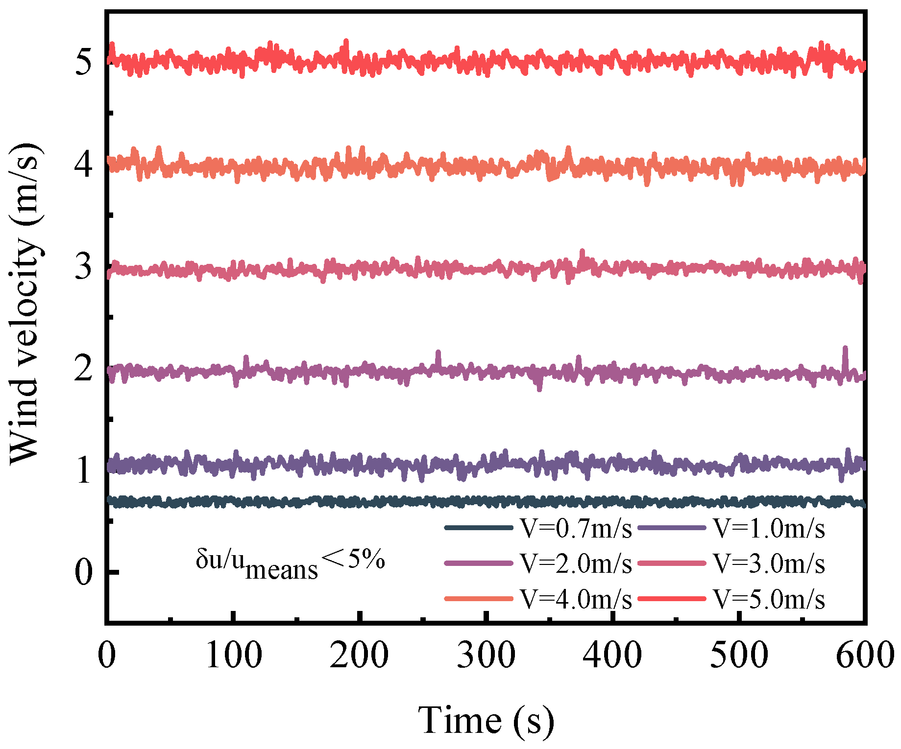
The experimental setup shown in Figure 1 utilized a wind tunnel to generate the necessary cross wind for the experiments. The total length of the wind tunnel was 11.0 m, and it featured a rectangular test section with dimensions of 0.8 m (height) × 1.0 m (width) × 1.2 m (length) where the pool-fire burning experiments were conducted. The test section’s ceiling, floor, and sidewalls were constructed using 2 mm thick steel plates. An observation window on the sidewall of the test section was made of 5 mm toughened glass to allow for observation of flame evolution. A pool fire was positioned at the center of the test section, with a baffle located upstream in front of the oil pool. The baffle consisted of steel bars measuring 1 m (length) × 2 cm (height) × 1 cm (thickness) and was fixed to the iron frames present on both sides of the sidewalls. Magnet blocks were embedded in the steel bars to ensure the stability of the baffle. The steel bars are fixed to the iron frames on both sides of the side walls, and magnet bars are embedded in the steel bars to ensure the stability of the baffle. The height of the baffle can be adjusted by changing the number of steel bars. The length of the baffle is equal to the width of the test section, thus ensuring that longitudinal wind will not flow through both sides of the baffle. A vertically installed hot-wire anemometer with an accuracy of 0.01 m/s was positioned 5 cm upstream from the baffle to monitor the transient cross wind speed across the cross-section of the test section. As shown in Figure 2, the ratios of the standard deviation of the ventilation velocity δu to the average ventilation velocity umeans were all less than 5%, indicating that the wind speeds were stable.
In the experiments, four variables were taken into consideration: baffle height (H), cross wind velocity (V), square pool size (D), and distance between the blockage baffle and the fire (Lb–). The top surface of the baffle was set at a height of 4 cm to 12 cm above the liquid face. The flame geometry was captured using a CCD camera with a resolution of 1920 × 1080 pixels and a frame rate of 30 frames per second. The camera was positioned 30 cm away from the observation window. The fire source was created using heptane pools with sizes of 8 cm × 8 cm and 12 cm × 12 cm, and n-heptane of 80 g and 130 g, respectively, was used before ignition. The pool pan was placed at the center of a 50 cm × 50 cm baseboard, beneath which lay an electronic balance with an accuracy of 0.01 g. During each fire test, the mass of the pool was recorded by the electronic balance per second and was promptly communicated to a laptop computer. The mass loss rate of the pool fire was then calculated. The distance between the blockage baffle and the fire (Lb–f) was set at 0 cm, 20 cm, and 30 cm, which was defined as the distance between the leeward side of the upstream baffle and the windward side of the downstream fire source. The experimental scenarios for different pool sizes, baffle heights, and cross wind velocities are listed in Table 1.
Two experiments were performed for each experimental scenario to reduce random errors. The uncertainty of the experimental results, which is mainly determined by the systematic error of the experimental setup and the random error in image processing, can be calculated by the formula Xi = Xl ± 2σ, where Xl is the mean value of repeated experiments and σ is the standard deviation, with ±2σ representing a 95% confidence interval [17]. The flame length parameter L and flame tilt angle parameters α and β defined in Section 3 were used to assess experimental uncertainty, and the results showed that the relative uncertainty of the experimental results was within 8% with a 95% confidence level. The average values of flame length and flame tilt angle obtained from two repeated experiments were used for subsequent analyses.

3. Results

3.1. Numerical Analysis

To investigate the mechanism of flame morphology variation, the FDS 6.7.1 simulation software was utilized to calculate the velocity field in a few typical experimental conditions. FDS is a computational fluid dynamics (CFD) model developed by the National Institute of Standards and Technology (NIST) to simulate fire-driven fluid flow. The software numerically solves a form of the Navier–Stokes equations appropriate for low-speed, thermally driven flow, with an emphasis on smoke and heat transport from fires [21]. A numerical simulation model (1.3 m × 1.0 m × 0.8 m) was established based on 1:1 dimensional ratio of the experimental wind tunnel’s test section. The wind inlet of the test section was set at one end, with the opening to the outside environment set at the other. Large Eddy simulation and Deardorff’s model were used to deal with the turbulent flow [21]. The materials used for the test section’s four sidewalls and baffles were steel with thermal properties deduced from the FDS database. The size of the simulated oil pool was 8 cm × 8 cm × 2 cm. The fuel that was employed was heptane (density 675 kg/m3, specific heat 2.24 kJ/kg·K, thermal conductivity 0.14 W/m·K, boiling point 98.5 °C), and the combustion reaction utilized heptane combustion data derived from the FDS database. The default large eddy simulation method of FDS was utilized for turbulence calculation. The accuracy and duration of the calculation rely on the size of the model grid. In order to ensure accuracy, it is generally believed that the mesh size δx should not be larger than 0.1D* [22], and it is recommended that the value of D*/δx could be in the range of 4~16 [23]. D* is the fire characteristic diameter and is represented as Q ˙ / ρ c p T g 2 / 5 [21]. According to the experimentally measured average mass burning rates, the D* values of the oil pan fire with D = 8 cm were between 0.12 m and 0.18 m at wind speeds ranging from 0.7 to 5 m/s. Therefore, to attain an enhanced computational accuracy, the grid size near the flame area (0.28 m × 0.08 m × 0.12 m) was set to 0.005 m, resulting in 21,504 grids. For the remaining areas, the grid size was set to 0.01 m, resulting in 1,037,312 grids. Overall, a total of 1,058,816 grids were used. Since a pool fire can quickly attain its maximum burning rate, the simulation burning time was set to 60 s with 23 °C ambient temperature.
The typical calculated flow field under various working conditions are illustrated in Figure 3, where the position of the baffle is located near x = 0. It is evident from the diagram that a low-speed wake is formed right behind the baffle, which transforms into a counterclockwise vortex flow as the baffle height increases to 12 cm. At a distance behind the baffle, a large clockwise recirculation zone is formed. The velocity of the recirculation zone increases with the rise in the incoming wind speed, and the size and velocity of the recirculation area also increase as the baffle’s height increases. Furthermore, the speed of the cross wind above the baffle increases as it progresses over the baffle. Different from the situation in the open space, the increment of wind speed above the baffle increases as the baffle height increases because the space above the baffle decreases. The calculation results also indicate that the distance between the flame and the baffle has little effect on the flow field.

3.2. Typical Flame Images

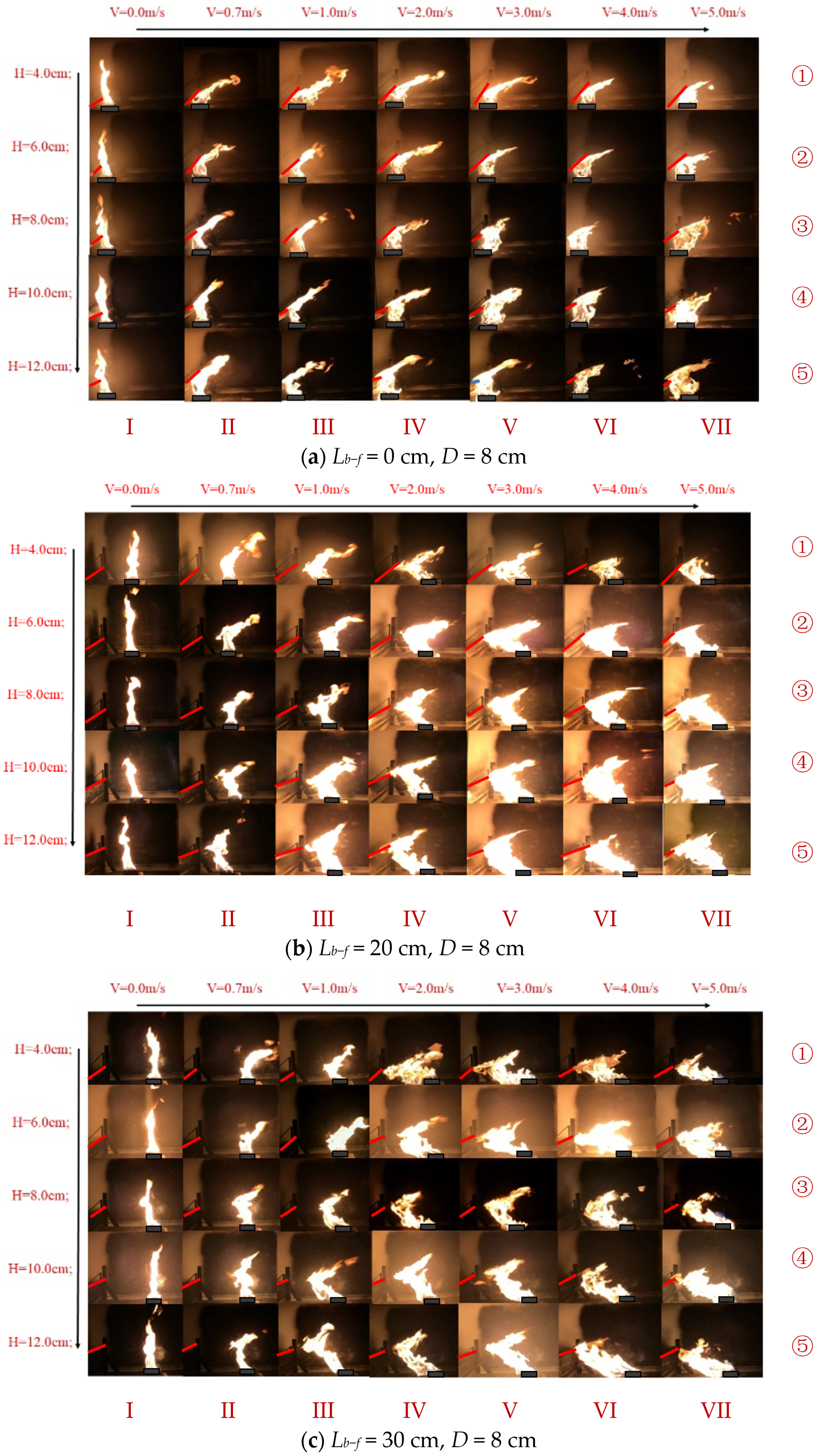
The flame shape is influenced by the hot flame buoyancy force and the external cross wind. Once the baffle is placed, the flame tends to be dominated by the recirculation flow behind the baffle and the enhanced flow above it. After the ignition of heptane, the entire burning process can be divided into an initial growth stage, a quasi-steady stage, and a decay stage. Figure 4a–c illustrate the effect of baffle height on the flame’s geometric properties during the quasi-steady burning stage, with a cross wind velocity ranging from 0 to 5 m/s and at different distances between the baffle and pool fire. The video’s exposure remains unchanged to scrutinize the flame’s brightness fluctuations.
When the wind speed is 0 m/s, the flame inclines slightly to the baffle, as shown in the first column (Line I) of Figure 4a–c. For a free burning flame, asymmetric entrainment occurs on both sides of the pool fire. However, when the baffle is present, there is inadequate air to entrain on the left side of the flame, causing it to lean towards the baffle to suction more air for combustion.
From Figure 4a, it is noticeable that when there is no gap between the pool fire and the baffle, the flame situated below the baffle closely attaches to it as a result of the combined effect of the cross winds and the baffle. At the same time, the flame above the baffle tilts towards the right. As the wind speed increases (as shown in Figure 4a from Line II to Line VII), the tilt angle of the upper flame increases, and the bottom flame volume expands to surpass the width of the oil pan owing to the restriction imposed by the baffle.
Furthermore, the flame geometry of the pool fire with a distance between the pan and baffle shows that the bottom part of the flame inclines toward the left, while the upper part of the flame inclines downstream as demonstrated in Figure 4b,c, which is consistent with the experimental results obtained by Chen et al. [18] under a 10 cm high baffle. Additionally, with an increase in the cross wind velocity in the wind tunnel (as shown in Figure 4b,c from Line II to Line VII), both the upper and bottom flames tilt more and brighten, and the flame volume increases accordingly. When the wind speed is between 0 and 0.7 m/s (Line II of Figure 4b,c), the bottom flame slightly tilts towards the baffle. As the wind speed reaches 1.0 m/s (Line III of Figure 4b,c), the degree of inclination increases significantly.
For low wind speeds (Lines II~III of Figure 4b and Lines II~V of Figure 4c), the flame-bending point can be observed behind the baffle. Corresponding to the respective distances between the flame and the baffle of 20 cm and 30 cm, as the wind speed increases to 2 m/s (Line IV of Figure 4b) and 4 m/s (Line VI of Figure 4c), the bending point of the flame will attach to the highest point of the baffle. When the height of the baffle increases, the flame-bending point moves up accordingly (as shown in Figure 4b,c from Line ① to Line ⑤).
At wind speeds below 3 m/s, the cross wind speed has little effect on the length of the flame above the baffle (as shown in Figure 4 from Line II to Line IV). However, when the cross wind speed exceeds 3 m/s, it is clear that the length of the flame above the baffle decreases significantly with increasing wind speed (as shown in Figure 4 from Line V to Line VII).
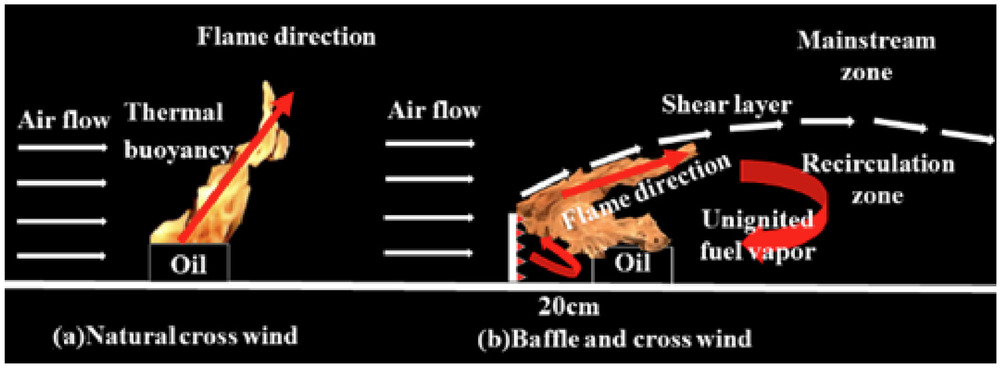
The simplified flow field shown in Figure 5 illustrates the factors that impact wind-blown fires with or without a baffle based on the simulation results of FDS. The presence of wind and a blockage baffle makes the air entrainment around the flame more complex, resulting in a curved flame and affecting the heat feedback mechanism. When the wind passes through the baffle, the flow field downstream of the baffle is divided into two zones: the mainstream zone and the recirculation zone. The recirculation zone exhibits the structure of the vortex flow with a low mean velocity and substantial turbulence [24,25]. If the fire is located in the recirculation area, two opposite forces pull the flame [26,27]. The momentum of the recirculation flow situated behind the baffle pulls the bottom flame towards the leeward side of the baffle, leading to a change in the flame’s shape. Meanwhile, the upper flame extending out of the baffle slopes downstream in the mainstream zone due to the enhanced cross wind.

3.3. Mass Burning Rate

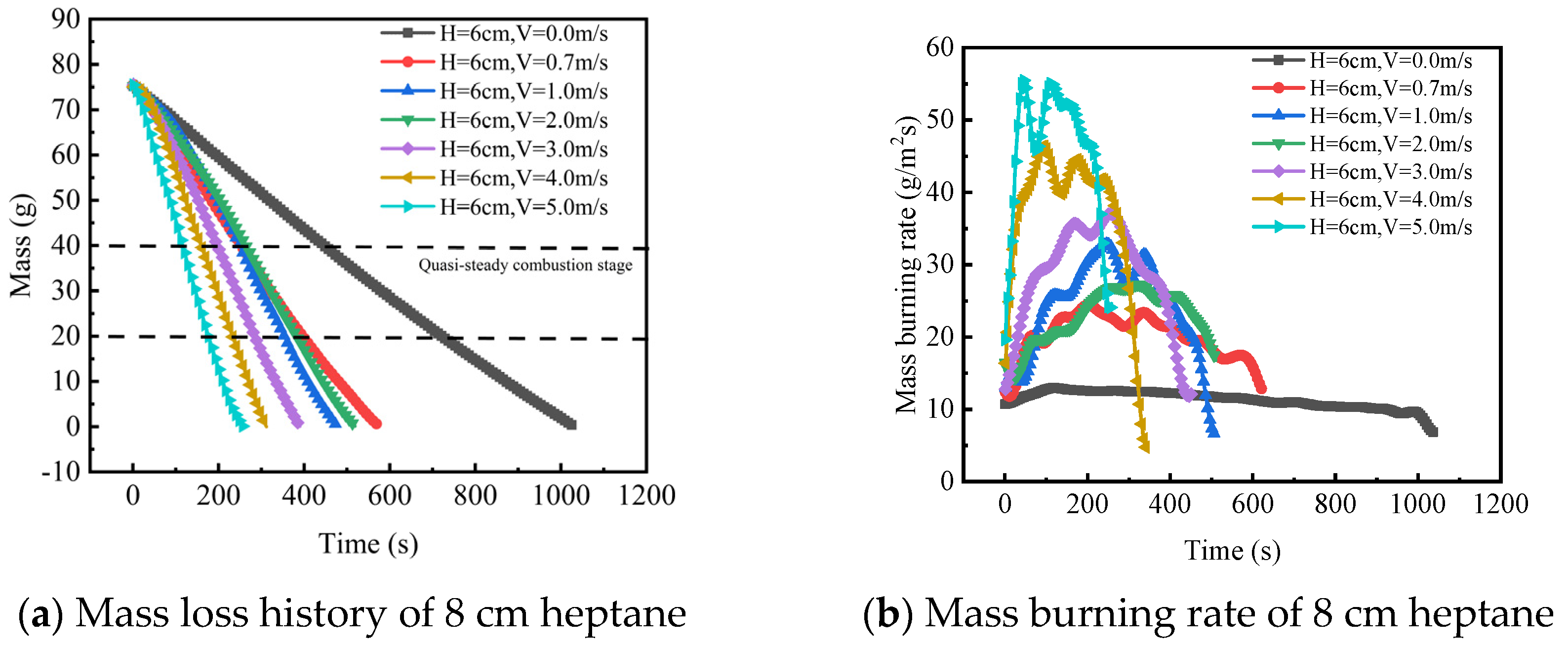
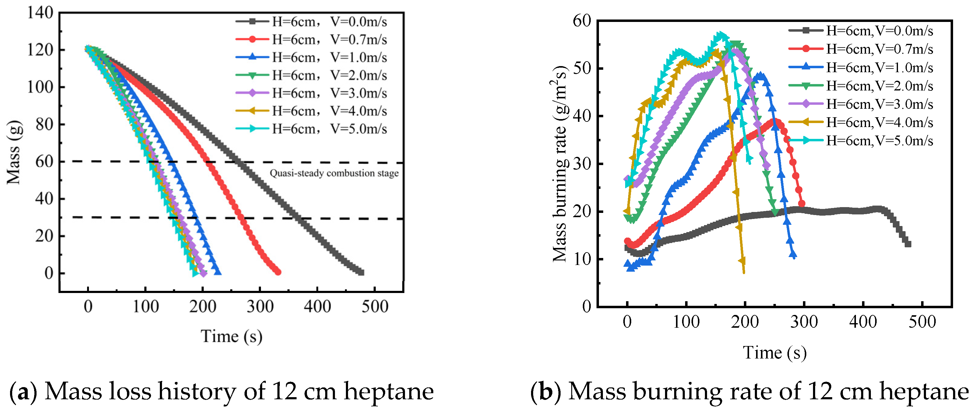
The time-variation curve of the oil pool’s mass loss was obtained by the balance, and the corresponding burning mass loss rate was derived [16,18]. The experimental results indicate that the flame burning rate trend with wind speed remains similar for different distances between the blockage baffle and the fire. Thus, the burning rate of a pool fire with Lb–f = 20 cm is taken as an example. In Figure 6 and Figure 7, the mass loss (a) and mass burning rate (b) of two-size pool fires with H = 6 cm and Lb–f = 20 cm are presented under different cross wind velocities. It is observed that as the cross wind velocity increases, the burning rates also increase, but the rate of increase gradually decreases. In particular, for the 12 cm pool fire, the maximum burning rate remains almost constant at wind velocities greater than 2 m/s. The increased burning rate causes the pool fire to enter the decay stage and extinguish faster under a high wind velocity. The recirculation zone downstream of the pool fire can circulate high-temperature fuel vapor and air back to the fire zone. As the wind velocity increases, the speed of the recirculation zone increases, and the circulation becomes more turbulent, as shown in Figure 3. This results in stronger thermal convection near the flame and enhanced mixing of oxygen and fuel. Consequently, the burning rate and size of the pool fire increase, as depicted in Figure 4. Under identical conditions, the 12 cm pan burns faster than the 8 cm pan, which is consistent with the experimental results of gasoline pool fires in a wind tunnel conducted by Hu et al. [28].
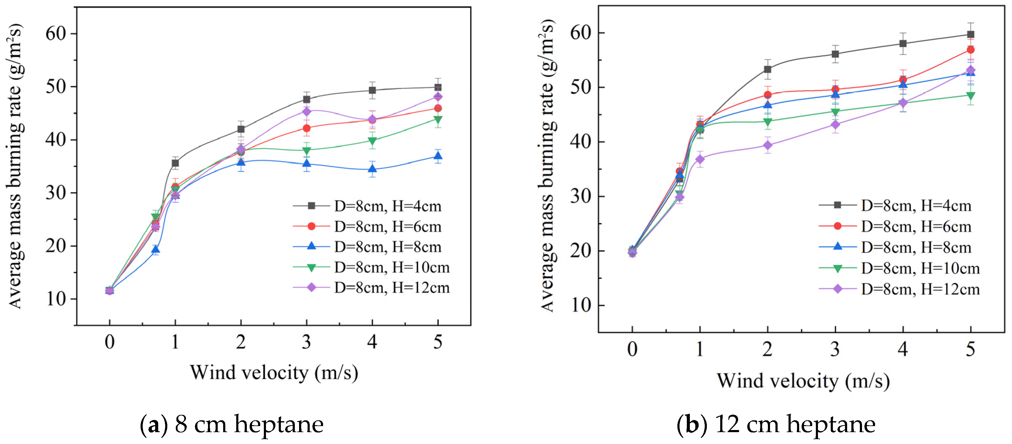
During the experiments, there is no obvious long-term stable stage for the mass burning rate, particularly under high cross wind speeds and using a 12 cm oil pan. However, a relatively stable flame shape is observed during a period close to the peak of the mass burning rate. Hence, the average burning rate during this period is chosen for a subsequent analysis. For the 8 cm oil pan, the chosen time period is when the fuel mass reduces from 40 g to 20 g, while for the 12 cm oil pan, it is when the fuel mass reduces from 60 g to 30 g. The average value of two repeated experiments is used for accuracy. The average burning rates of pool fires with different baffle heights in the cross wind are shown in Figure 8. In general, rising trends are identified for burning rates of varied baffle heights with an increase in cross wind velocity.
The average burning rates at different baffle heights are close when the cross wind velocities are low. However, as the wind speed exceeds 2 m/s, the difference in average burning rates increases at different baffle heights. According to the research of Hu et al. on the combustion characteristics of pool fires in cross wind environments without obstructions, longitudinal air flow can increase the turbulence of the flame, upgrade the flame temperature, and enhance the radiation to the fuel, thereby accelerating the burning rate [28]. When the baffle is installed, the flame is divided into two parts: the bottom flame below the height of the baffle, and the upper flame above the baffle. Due to the obstruction of the baffle to the longitudinal wind, only the upper flame is directly affected by the inflow wind, while the bottom flame is solely influenced by the recirculation flow. However, the wind speed in the recirculation zone is significantly lower than that of the inflow, which weakens its effect on the increasing flame combustion intensity caused by the cross wind. Therefore, setting up a baffle will reduce the burning rate of the pool fire.
As the height of the baffle increases, the proportion of the bottom flame zone increases, thus reducing the mass burning rate of the pool fire. In Figure 8a, it is shown that for a D = 8 cm pool fire, when the baffle height is 4 cm, the average burning rate is highest. As the baffle height increases from 4 cm to 8 cm, the burning rate gradually decreases. When the height of the baffle is further increased to 10 cm, most of the flames are located below the baffle, with few flames above the baffle. The combustion intensity of the flames is mainly influenced by the recirculation flow. Additionally, as the height of the baffle increases, the tilt angle of the bottom flame decreases, which increases the heat radiation of the flame to the fuel surface. Therefore, as the height of the baffle increases from 8 cm to 10 cm, the average burning rate of the D = 8 cm pool fire increases. For larger pool fires (D = 12 cm) with longer flame heights, the fuel’s burning rate rises with growing baffle heights at higher baffle heights as shown in Figure 8b.
Blinov and Khudiakov [29] proposed an equation that relates wind velocity to the ratio of the mass burning rate in windy environments versus still air. It can be expressed as:
m ˙ windy   m ˙ still   = 1 + 0.15 V D ˙ ,
As for the dimensionless heat release rate Q ˙ * ,
Q ˙ * = Q ˙ ρ C P T g D ˙ 5 = m ˙ S Δ H c ρ C P T g D ˙ 5 ,
where Q ˙ is the HRR, ρ is air density (1.205 k g / m 3 ), C P is heat capacity (1.005 k J / k g ) , T is ambient temperature (293.15 K), g is gravity acceleration (9.8 m / s 2 ), m ˙ is burning rate ( g / m 2 s ) ,   S is the combustion surface area of the pool (m2), Δ H c is the combustion heat ( 44 , 600   k J / k g ) [30], and D ˙ is the equivalent circular pan diameter (m), i.e., D ˙ = 2 D / π for the square pools used in this study.
Based on Equation (1) and the results of the heptane pool fire combustion experiments, the relationship between the dimensionless heat release rate Q ˙ * , the baffle height H, and the cross wind speed V can be expressed by Equation (3).
Q ˙ * = 1 + a V D ˙ + H b ,
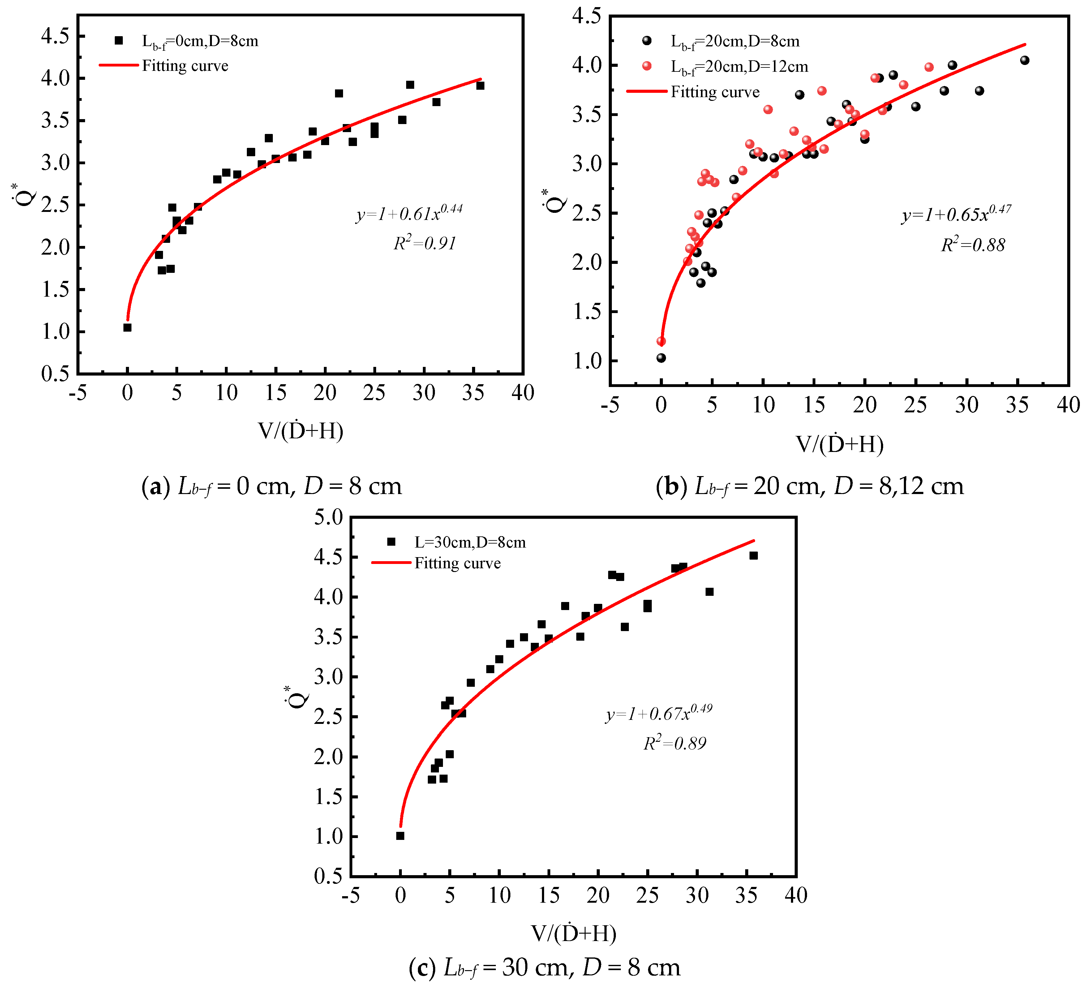
It can be observed from Figure 9 that there is a positive association between the ratio of V D ˙ + H and Q ˙ * . The prediction presented in Equation (4) is the result of the fitting process.
Q ˙ * = 1 + 0.61 V D ˙ + H 0.44 , L b f = 0   cm 1 + 0.65 V D ˙ + H 0.47 , L b f = 20   cm 1 + 0.67 V D ˙ + H 0.49 , L b f = 30   cm

3.4. Flame Length and Tilt Angle

3.4.1. Definitions

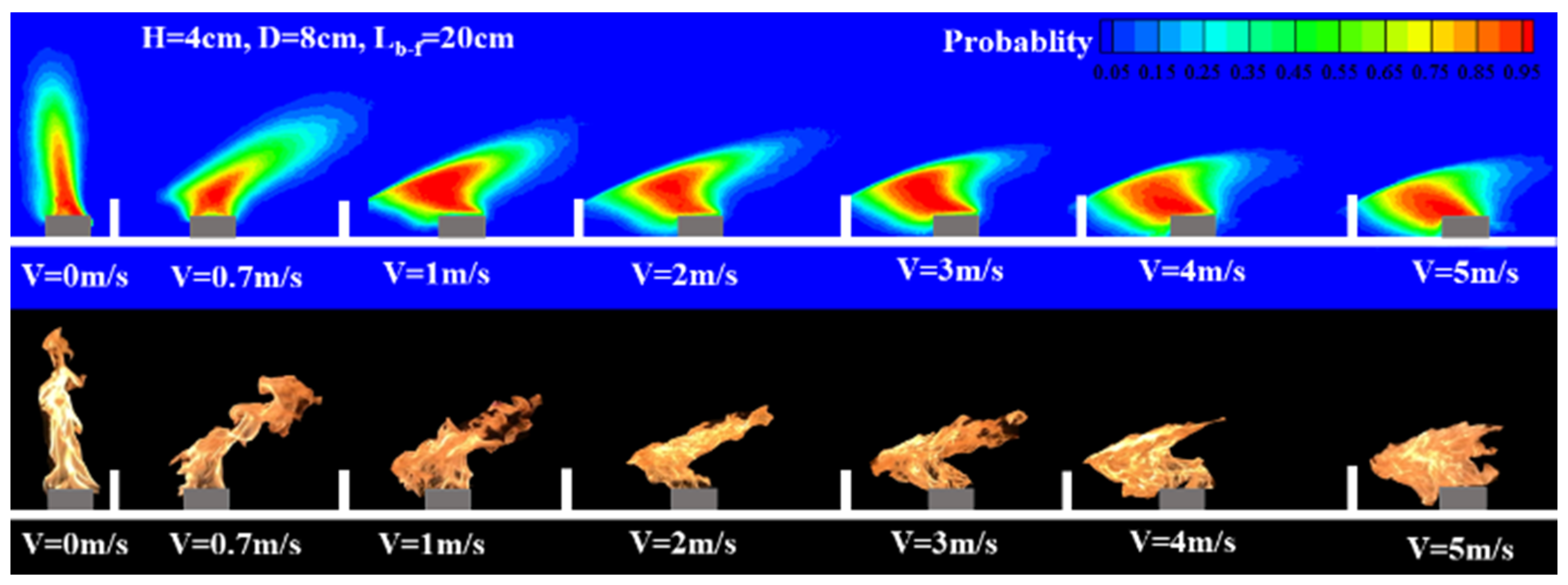
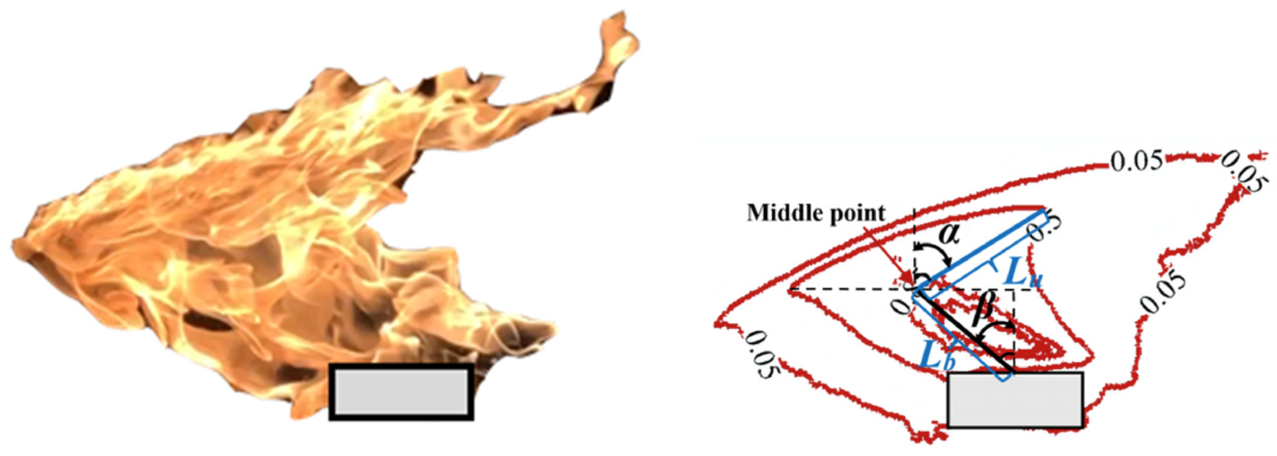
The characteristic parameters of flame shape are determined by processing video images. Flame pictures are acquired from the video recording and transformed into binary images using the Otsu [31] method in MATLAB to derive a threshold value. These images are then overlaid and averaged to create the flame appearance probability contour. A threshold of 50% for the flame appearance probability is utilized to establish the mean flame shape and quantify the flame’s geometric characteristics. Based on the experimental results, typical flame features for a D = 8 cm pool fire with the baffle height H = 4 cm and the distance between the baffle and fire L = 20 cm are depicted in Figure 10.
Due to the bending effects of cross winds on flames, the flame can be divided into two parts: the bottom part, which is close to the baffle or inclined towards the baffle (Lb), and the upper part, which is inclined towards the downstream direction (Lu), as shown in Figure 11. To determine Lb and Lu, the midpoint of the horizontal line that runs from the turning point on the left side of the 0.5 intermittency flame to the intersection with the outer contour of the 0.5 intermittency flame on the right side is used as the point of inflection. Lb is the distance from the center of the fire source to the midpoint, while Lu is the distance from the midpoint to the top of the flame. The sum of Lb and Lu is used to calculate the total flame length (L). Additionally, the angle between the flame tip and the midpoint and the perpendicular line is defined as the upper flame tilt angle α, while the angle between the center of the fire source and the midpoint and the perpendicular line is defined as the bottom flame tilt angle β, as shown in Figure 11. Since the two inclinations are opposite, the downwind direction is assigned as positive.

3.4.2. Flame Length

The length of a wind-blown flame is determined by the interplay between its inherent vertical buoyancy and the horizontal momentum imparted by the wind [32]. When considering flames in a windy environment, the Tang [10] empirical correlation can be used to calculate their length:
L D ˙ = 0.8 F r 0.5 + 2.8 ,
F r = V 2 g D ˙ ,
L is the flame length (m), D ˙ is the equivalent circular pan diameter (m), g is gravity acceleration (9.8 m / s 2 ), F r is the Froude number, and V is the cross wind velocity (m/s).
The flame length is influenced by wind velocity, baffle height, and heat release rate. Therefore, the dimensionless flame length can be expressed as a function of L / D ˙ V ,   H , Q ˙ * .
Furthermore, a new dimensionless coefficient F h is proposed to enable the holistic quantification of the factors affecting flame length, F h V , H ,
F h = V 2 g ( D ˙ + H ) ,
Limit analysis is performed on F h to confirm its feasibility. When H → 0, it can be seen as a wind-blown fire without blocking; when H , the baffle will completely block the wind, the flame will not be influenced by the wind, and its length will be the same as when there is no wind.
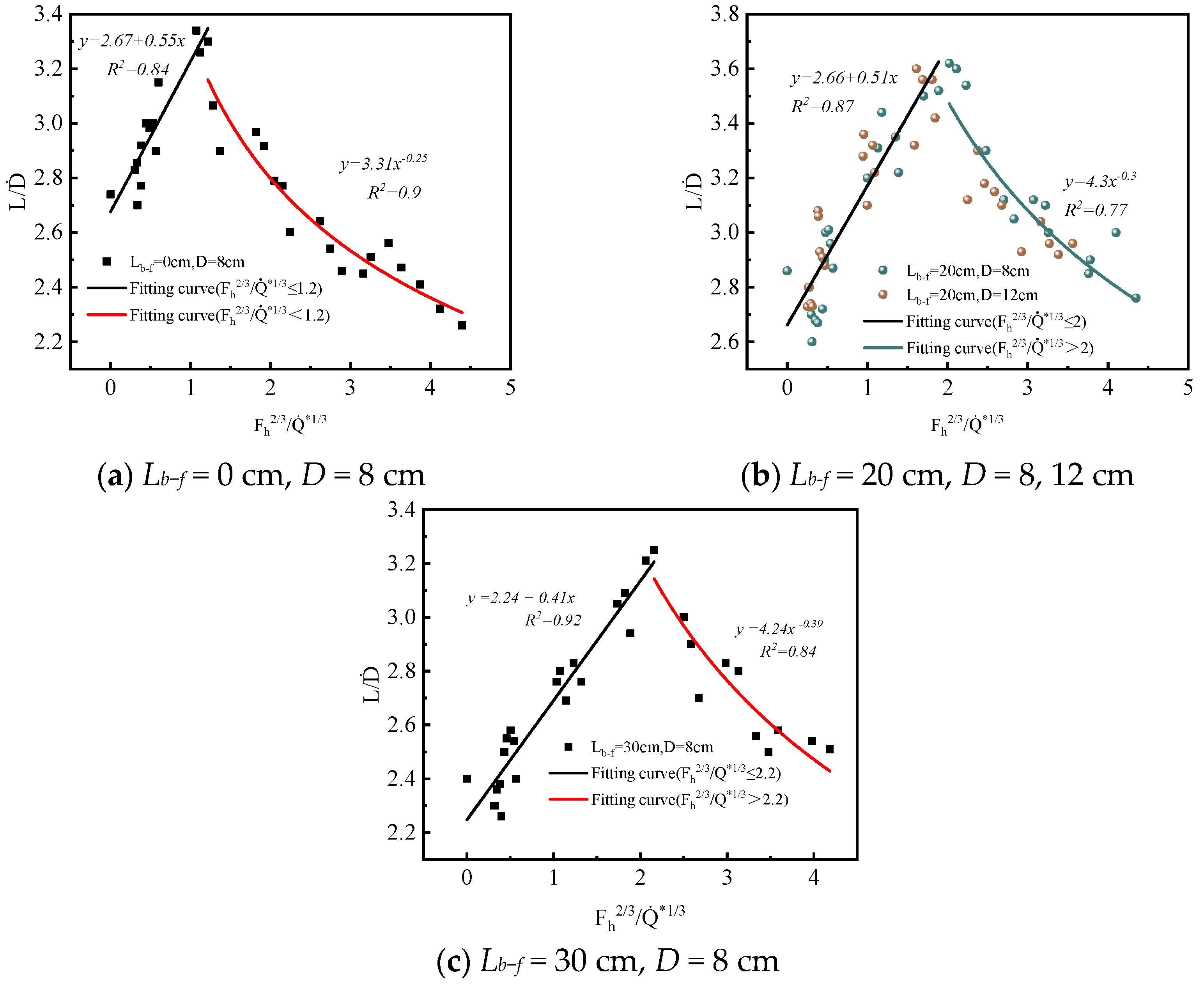
In total, taking F h a / Q ˙ * b [33,34] as the abscissa and the dimensionless flame length L / D ˙ as the ordinate, an expression is used to represent the functional relationship between the two parameters in Figure 12, which shows that the flame length of the pool fire increases at first and eventually declines as Fh2/3/ Q ˙ *1/3 grows. It is observed that the coefficient of the function formula varies for different flame and baffle spacings. However, the size of the pool has a negligible effect on the functional relationship.
In general, the flame length is expressed as:
L D ˙ = 2.67 + 0.55 F h 2 / 3 Q ˙ * 1 / 3 ,   F h 2 / 3 Q ˙ * 1 / 3 1.2 ;   3.31 ( F h 2 / 3 Q ˙ * 1 / 3 ) 0.25 ,   F h 2 / 3 Q ˙ * 1 / 3 > 1.2 ;   L b f = 0 cm L D ˙ = 2.66 + 0.51 F h 2 / 3 Q ˙ * 1 / 3 ,   F h 2 / 3 Q ˙ * 1 / 3 2 ;   4.3 ( F h 2 / 3 Q ˙ * 1 / 3 ) 0.3 ,   F h 2 / 3 Q ˙ * 1 / 3 > 2 ;   L b f = 20 cm L D ˙ = 2.24 + 0.41 F h 2 / 3 Q ˙ * 1 / 3 ,   F h 2 / 3 Q ˙ * 1 / 3 2.2 ;   4.24 ( F h 2 / 3 Q ˙ * 1 / 3 ) 0.39 ,   F h 2 / 3 Q ˙ * 1 / 3 > 2.2 ;   L b f = 30 cm
When Lb–f is 0 cm, the dimensionless flame length reaches its maximum at Fh2/3/ Q ˙ *1/3 = 1.2 and then drops as Fh2/3/ Q ˙ *1/3 > 1.2; when Lb–f is 20 cm, the dimensionless flame lengths for pool fires with sizes of 0.08 m and 0.12 m both reach their maximum at Fh2/3/ Q ˙ *1/3 = 2 and then begin to decline as Fh2/3/ Q ˙ *1/3 > 2; when Lb–f is 30 cm, the dimensionless flame length reaches its maximum at Fh2/3/ Q ˙ *1/3 = 2.2 and then begins to decline as Fh2/3/ Q ˙ *1/3 > 2.2.

3.4.3. Flame Tilt Angle

Cross winds can accelerate the spread of fire by transferring additional heat, especially radiation heat, downstream, which can ignite the surrounding materials [35]. Therefore, the angle at which the flames tilt is an essential factor in determining the risk of fire propagation [36,37].
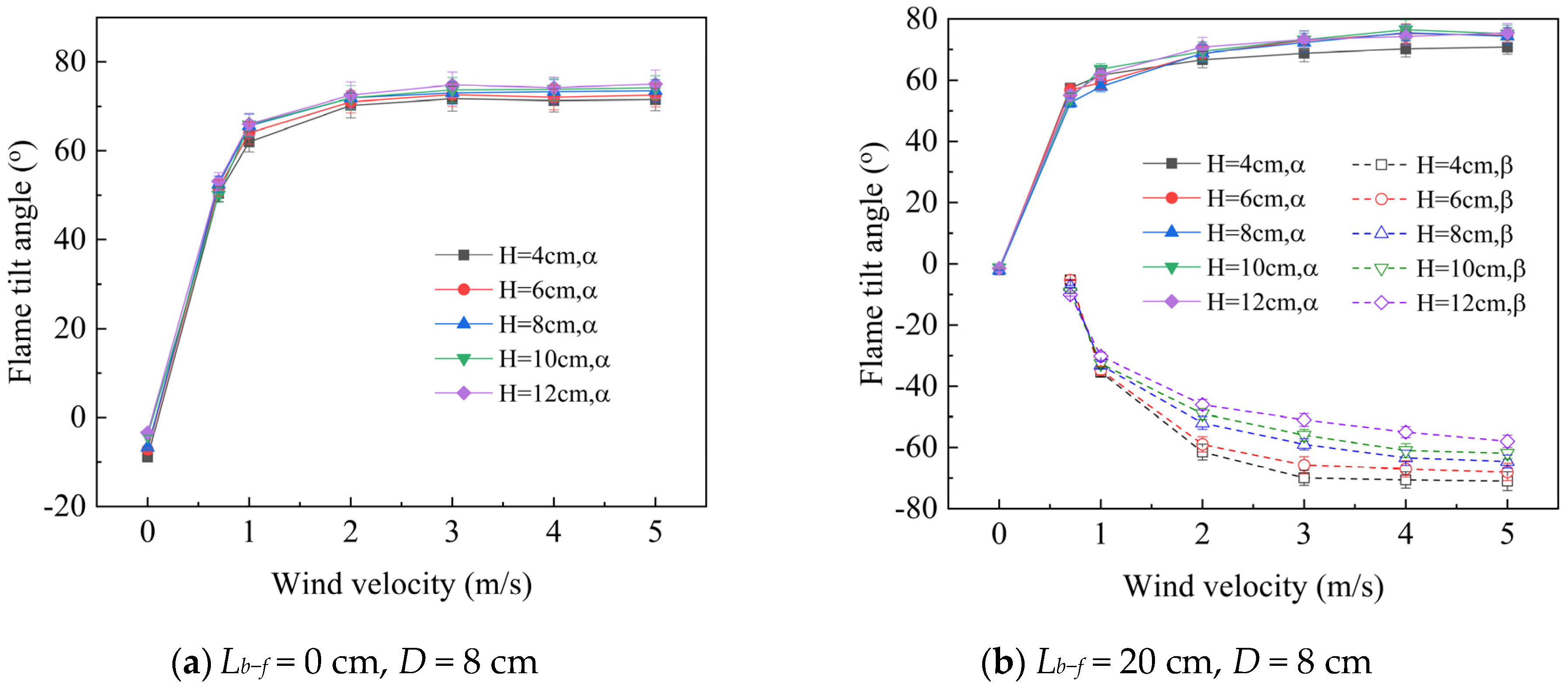
Figure 13 illustrates the flame tilt angle α and β under varying fire test conditions. When there is no wind, the angle α is used to represent the overall tilt of the flame since the flame is mostly straight. As discussed before, the flame tilts slightly to the left in this situation, with α slightly less than 0°. However, when the oil pan is in close contact with the baffle, the tilt angle of the flame is slightly larger due to the influence of the baffle. When a cross wind is present and the wind speed is less than 1 m/s, the flame tilt angle α initially increases rapidly, and then the rate of increase gradually decreases with the increase in cross wind speed. When the wind speed exceeds 3 m/s, the flame tilt angle α approaches 75° and changes very slightly with the cross wind. The height of the baffle has little effect on the tilt angle α. According to the calculation results of the FDS, the wind speed in the mainstream above the baffle increases slightly with the increase in the baffle height; therefore, the flame tilt angle α also increases slightly accordingly.
The flame tilt angle β increases rapidly when the cross wind velocity is less than 2 m/s, and then the growth rate gradually decreases with a further increase in the cross wind velocity. The inclination of the bottom flame becomes smaller with the increase in the height of the baffle. This is due to the limiting effect of the baffle on the flame’s inclination, as well as the lifting effect of the vortex flow between the flame and the baffle. When the value of Lb–f is 0 cm, the baffle blocking prevents the bottom flame from tilting to the left side, resulting in an inclination angle β that is nearly 0°. On the other hand, when Lb–f is 30 cm, the upper flame above the baffle disappears, and there is no tilt angle α when the baffle height is 10 cm and the wind velocity is greater than 5 m/s. Similarly, when the baffle height is 12 cm and the wind velocity is greater than 4.5 m/s, there is no tilt angle α, as shown in Figure 13d.
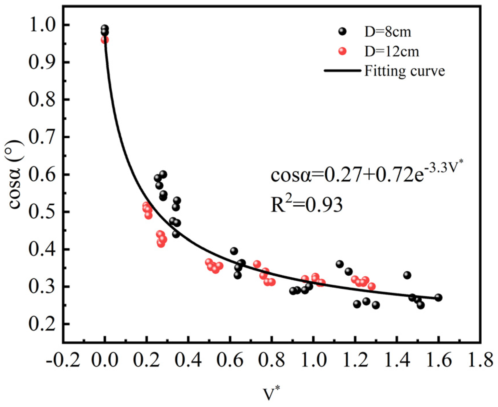
Many empirical formulas have been developed to characterize the flame tilt angle [36]. In these fire tests, the influence of the baffle can be ignored for the upper flame tilt angle α. Figure 14 depicts the fitting function curve and experimental value of the flame tilt angle α when the distance Lb–f = 20 cm. The graph shows that the cosine value of the upper flame tilt angle has a negative exponent relationship to the dimensionless wind velocity V*. This relationship can be mathematically expressed in Equation (9) as the cosine value of the tilt angle α.
cosα = 0.27 + 0.72e−3.3V*,
V * is the dimensionless wind velocity.
V * = V g m ˙ D ˙ ρ 1 / 3 ,

4. Conclusions

This study investigated the impact of cross winds on the flame downstream of the baffle in a wind tunnel. The research focuses on parameters such as flame shape, burning rate, length, and tilt angle. The key findings of this investigation are as follows:
  • The flame behind the baffle bends due to the pulling forces in two opposite directions. The bottom flame below the baffle is pulled towards the baffle by the momentum of the recirculation flow behind it. The upper flame above the baffle is fanned and extends downstream by the cross wind in the mainstream zone.
  • The burning rate of the pool fire increases and the fire size enlarges as the cross wind velocity increases. With an increase in baffle height, the burning rate initially decreases and then gradually increases. Empirical correlations have been proposed to predict the dimensionless heat release rate Q ˙ * in relation to the baffle height and cross wind velocity with different distances between the baffle and flame.
  • The flame length increases at first and then decreases as the wind velocity increases due to the combined effects of the baffle and cross wind. To quantify the relationship between the flame length, baffle height, and cross wind velocity, a dimensionless coefficient, Fh, has been introduced.
  • The tilt angle α of the upper flame is primarily influenced by cross wind, which increases rapidly when the ventilation velocity is below 1 m/s and then remains constant. The tilt angle β of the bottom flame is affected by three factors. When the cross wind velocity or the distance between the baffle and fire increases, the tilt angle β becomes larger. Conversely, when the baffle height increases, the tilt angle β becomes smaller.
  • Based on the experimental results, it can be predicted that the presence of ventilation and obstacles within the aircraft engine nacelle will increase the intensity of oil leakage fires and tilt the flame, therefore increasing the likelihood of the flame spreading. To decrease the intensity of the flames and slow down the rate of spreading, it is recommended to lower the ventilation intensity within the aircraft engine nacelle in the event of a fire, and to avoid placing combustible materials such as cables near obstacles. This study only focused on specific conditions involving particular wind speeds and obstacle heights. Further research is needed, including scaled and full-scale fire experiments, to achieve a deeper understanding of the characteristics of aircraft engine fires.

Author Contributions

Conceptualization, methodology, writing—review and editing, supervision, funding acquisition, X.H.; investigation, data curation, writing—original draft preparation, Z.Y.; software, visualization, Z.Z. All authors have read and agreed to the published version of the manuscript.

Funding

This work was supported by the Joint Funds of the National Natural Science Foundation of China, “False alarm immunity fire detection mechanism and key technologies of civil aviation aircraft cargo compartment” [Grant No. U2133201] and the Science and Technology Program of Tianjin, “Research on fire characteristics and advanced halo-carbon fire extinguishing technology of domestic civil aircraft” [Grant No. 21JCZDJC00810].

Institutional Review Board Statement

Not applicable.

Informed Consent Statement

Not applicable.

Data Availability Statement

Data are contained within the article.

Conflicts of Interest

The authors declare no conflicts of interest. The funders had no role in the design of the study; in the collection, analyses, or interpretation of data; in the writing of the manuscript; or in the decision to publish the results.

References

  1. Gann, R.G. Advanced Technology for Fire Suppression in Aircraft; National Institute of Standards and Technology: Gaithersburg, MD, USA, 2007.
  2. Wild, T.W. Aircraft: Powerplants, 9th ed.; McGraw-Hill Education: New York, NY, USA, 2018. [Google Scholar]
  3. Gann, R.G. Guidance for advanced fire suppression in aircraft. Fire Technol. 2008, 44, 263–282. [Google Scholar] [CrossRef]
  4. Hradecky, S. Incident: Aerostan B742 at Macau on Nov 23rd 2022, Engine Shut Down in Flight, The Aviation Herald. 2022. Available online: https://avherald.com/h?article=5017f4ef (accessed on 24 November 2022).
  5. Takahashi, F.; Schmoll, W.; Belovich, V. Suppression of bluff-body stabilized diffusion flames. In Proceedings of the 34th AIAA/ASME/SAE/ASEE Joint Propulsion Conference and Exhibit, Cleveland, OH, USA, 13–15 July 1998. [Google Scholar] [CrossRef]
  6. Takahashi, F.; Schmoll, W.; Strader, E.A. Suppression behavior of obstruction-stabilized pool flames. Combust. Sci. Technol. 2001, 163, 107–130. [Google Scholar] [CrossRef]
  7. Hirst, R.; Farenden, P.J.; Simmons, R.F. The extinction of fires in aircraft jet engines—Part I, small-scale simulation of fires. Fire Technol. 1976, 12, 266–275. [Google Scholar] [CrossRef]
  8. Hirst, R.; Farenden, P.J.; Simmons, R.F. The extinction of fires in aircraft jet engines—Part II, full-scale fire tests. Fire Technol. 1977, 13, 59–67. [Google Scholar] [CrossRef]
  9. Hu, L.; Liu, S.; Xu, Y.; Li, D. A wind tunnel experimental study on burning rate enhancement behavior of gasoline pool fires by cross air flow. Combust. Flame 2011, 158, 586–591. [Google Scholar] [CrossRef]
  10. Tang, F.; Li, L.J.; Zhu, K.J.; Qiu, Z.W.; Tao, C.F. Experimental study and global correlation on burning rates and flame tilt characteristics of acetone pool fires under cross air flow. Int. J. Heat Mass Transf. 2015, 87, 369–375. [Google Scholar] [CrossRef]
  11. Oka, Y.; Sugawa, O.; Imamura, T.; Matsubara, Y. Effect of cross-winds to apparent flame height and tilt angle from several kinds of fire source. Fire Saf. Sci. 2003, 7, 915–926. [Google Scholar] [CrossRef]
  12. Ouyang, R.; Zhao, W.; Yang, L.; Jiao, A.; Xu, Z.; Fan, C. An experimental investigation of burning rate and flame geometric parameters of tunnel fires under canyon cross wind and longitudinal ventilation. Fire Saf. J. 2021, 126, 103474. [Google Scholar] [CrossRef]
  13. Mao, S.; Liu, S.; Yu, S.; Li, B.; Hao, W.; Chen, H. Experimental investigation of the burning characteristics of aviation fuel under atmospheric crosswind conditions. Fuel 2023, 332, 125981. [Google Scholar] [CrossRef]
  14. Ji, J.; Li, F.; Lu, W.; Sun, R.; Wang, K.; Cao, Y. An experimental study on flame geometry in wind-blown pool fires and a new dimensionless parameter. Case Stud. Therm. Eng. 2022, 30, 101782. [Google Scholar] [CrossRef]
  15. Ingason, H.; Li, Y.Z. Model scale tunnel fire tests with longitudinal ventilation. Fire Saf. J. 2010, 45, 371–384. [Google Scholar] [CrossRef]
  16. Shafee, S.; Yozgatligil, A. An analysis of tunnel fire characteristics under the effects of vehicular blockage and tunnel inclination. Tunn. Undergr. Space Technol. 2018, 79, 274–285. [Google Scholar] [CrossRef]
  17. Cong, W.; He, K.; Yang, H.; Peng, M.; Nan, T.; Shi, L.; Cheng, X. Effects of blockage on the flame morphologic characteristics in a ventilated tunnel. Tunn. Undergr. Space Technol. 2022, 123, 104410. [Google Scholar] [CrossRef]
  18. Chen, X.; Ding, Z.; Lu, S. Investigation of sidewall height effect on the burning rate and flame tilt characteristics of pool fire in cross wind. Fire Saf. J. 2021, 120, 103111. [Google Scholar] [CrossRef]
  19. Meng, N.; Liu, B.; Li, X.; Jin, X.; Huang, Y.; Wang, Q. Effect of blockage-induced near wake flow on fire properties in a longitudinally ventilated tunnel. Int. J. Therm. Sci. 2018, 134, 1–12. [Google Scholar] [CrossRef]
  20. Yu, Z.; Huang, X. Study of baffle height and wind velocity effect on the characteristics of pool fires in a wind tunnel. Appl. Sci. 2023, 13, 1920. [Google Scholar] [CrossRef]
  21. McGrattan, K.; Hostikka, S.; Floyd, J.; Vanella, M.; Craig, W.; Overholt, K. Fire Dynamics Simulator, User’s Guide; NIST Special Publication 1019, 6th ed.; National Institute of Standards and Technology: Gaithersburg, MD, USA, 2017.
  22. McGrattan, K.; Baum, H.; Rehm, R. Large eddy simulation of smoke movement. Fire Saf. J. 1998, 30, 161–178. [Google Scholar] [CrossRef]
  23. Hill, K.; Dreisbach, J.; Joglar, F.; Najafi, B.; McGrattan, K.; Peacock, R.; Hamins, A. Verification and Validation of Selected Fire Models for Nuclear Power Plant Applications; United States Nuclear Regulatory Commission: Washington, DC, USA, 2007.
  24. Raghunandan, B.N.; Yogesh, G.P. Recirculating flow over a burning surface—Flame structure and heat transfer augmentation. Symp. Int. Combust. 1989, 22, 1501–1507. [Google Scholar] [CrossRef]
  25. Siller, H.A.; Fernholz, H.H. Separation behaviour in front of a two-dimensional fence. Eur. J. Mech.-B/Fluids 2001, 20, 727–740. [Google Scholar] [CrossRef]
  26. Counihan, J.J.C.R.; Hunt, J.C.R.; Jackson, P.S. Wakes behind two-dimensional surface obstacles in turbulent boundary layers. J. Fluid Mech. 1974, 64, 529–564. [Google Scholar] [CrossRef]
  27. Schofield, W.H.; Logan, E. Turbulent shear flow over surface mounted obstacles. Transactions of the ASME. J. Fluids Eng. 1990, 112, 376–385. [Google Scholar] [CrossRef]
  28. Hu, L.H.; Liu, S.; Peng, W.; Huo, R. Experimental study on burning rates of square/rectangular gasoline and methanol pool fires under longitudinal air flow in a wind tunnel. J. Hazard. Mater. 2009, 169, 972–979. [Google Scholar] [CrossRef] [PubMed]
  29. Blinov, V.I.; Khudyakov, G.N. Diffusion Burning of Liquids; Army Engineer Research and Development Labs: Fort Belvoir, VA, USA, 1961. [Google Scholar]
  30. Hurley, M.J.; Gottuk, D.T.; Hall, J.R., Jr.; Harada, K.; Kuligowski, E.D.; Puchovsky, M.; Wieczorek, C.J. SFPE Handbook of Fire Protection Engineering; Springer: Cham, Switzerlands, 2015. [Google Scholar] [CrossRef]
  31. Otsu, N. A threshold selection method from gray-level histograms. IEEE Trans. Syst. Man Cybern. 1979, 9, 62–66. [Google Scholar] [CrossRef]
  32. Hu, L. A review of physics and correlations of pool fire behaviour in wind and future challenges. Fire Saf. J. 2017, 91, 41–55. [Google Scholar] [CrossRef]
  33. Oka, Y.; Kurioka, H.; Satoh, H.; Sugawa, O. Modelling of unconfined flame tilt in cross-winds. Fire Saf. Sci. 2000, 6, 1101–1112. [Google Scholar] [CrossRef]
  34. Gao, W.; Liu, N.; Jiao, Y.; Xie, X.; Pan, Y.; Li, Z.; Tu, R. Flame length of buoyant turbulent slot flame. Proc. Combust. Inst. 2019, 37, 3851–3858. [Google Scholar] [CrossRef]
  35. Zhou, B.; Yoshioka, H.; Noguchi, T.; Ando, T. Experimental study on vertical temperature profile of buoyant window spill plume from intermediate-scale compartments. Fire Mater. 2020, 44, 516–529. [Google Scholar] [CrossRef]
  36. Thomas, P.H. The size of flames from natural fires. Symp. Int. Combust. 1963, 9, 844–859. [Google Scholar] [CrossRef]
  37. Zhou, B.; Yoshioka, H.; Noguchi, T.; Wang, K.; Huang, X. Upward fire spread rate over real-scale EPS ETICS Facades. Fire Technol. 2021, 57, 2007–2024. [Google Scholar] [CrossRef]
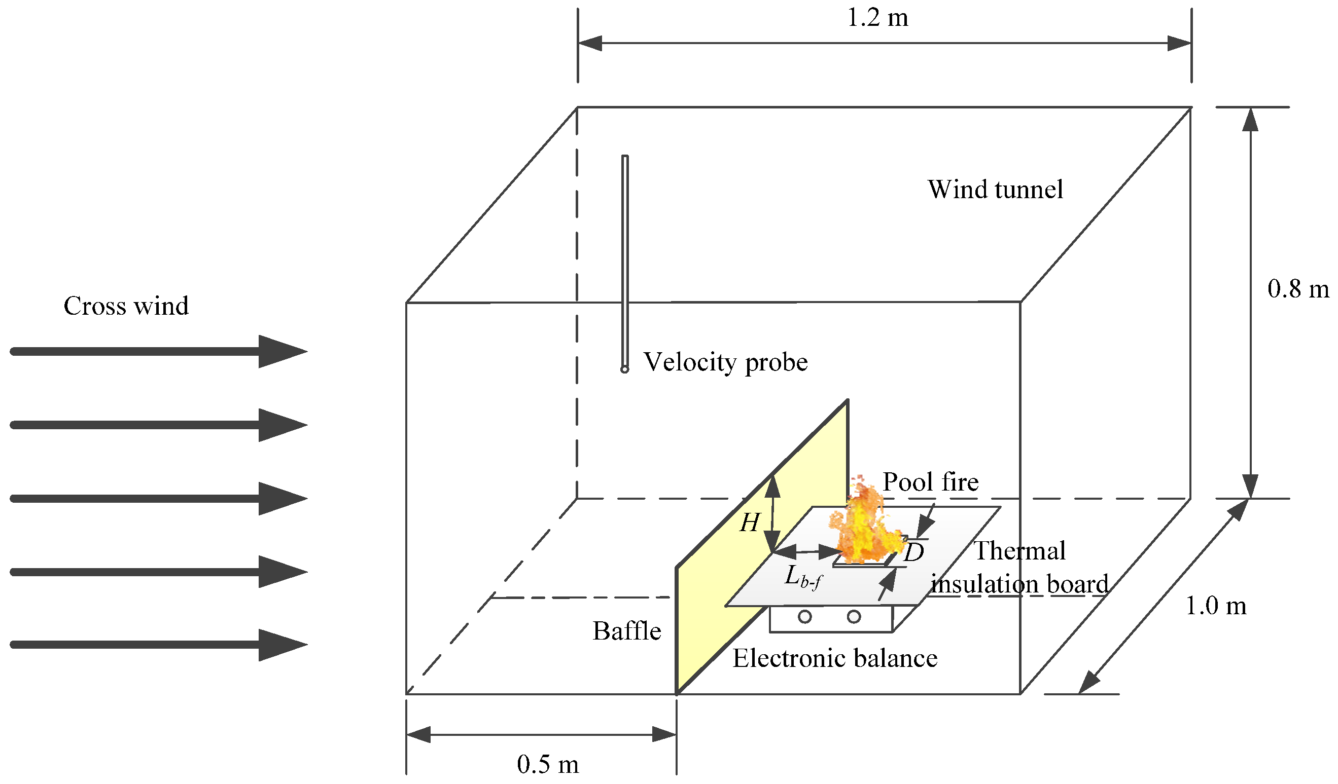
Figure 1. Diagram of the experimental section.
Fire 07 00004 g001
Figure 2. Instantaneous horizontal wind speeds.
Fire 07 00004 g002
Figure 3. Flow field in the wind tunnel.
Fire 07 00004 g003
Figure 4. Flame evolution of pool fires. (Red lines are marked at the upper edge of the baffles.)
Fire 07 00004 g004
Figure 5. Structure of non-blockage and blockage flow field.
Fire 07 00004 g005
Figure 6. Mass loss and mass burning rates of pool fires at different cross wind velocities (D = 8 cm, H = 6 cm, Lb−f = 20 cm).
Fire 07 00004 g006
Figure 7. Mass loss and mass burning rates of pool fires at different cross wind velocities (D = 12 cm, H = 6 cm, Lb-f = 20 cm).
Fire 07 00004 g007
Figure 8. Average burning rate of pool fires with the different baffle heights in cross wind.
Fire 07 00004 g008
Figure 9. Correlation between V D ˙ + H and Q ˙ * .
Fire 07 00004 g009
Figure 10. Images of heptane pool fires under different cross wind velocities.
Fire 07 00004 g010
Figure 11. Definitions of the flame tilt angle and flame length.
Fire 07 00004 g011
Figure 12. Correlation between L/ D ˙ and Fh2/3/ Q ˙ *1/3.
Fire 07 00004 g012
Figure 13. Flame tilt angles of pool fires with different baffle heights under different cross wind velocities.
Fire 07 00004 g013aFire 07 00004 g013b
Figure 14. Relationship between fitting value and experimental value of flame tilt angle α.
Fire 07 00004 g014
Table 1. Experimental scenarios.
Test No.D (cm)Lb−f (cm)V (m/s)H (cm)
1–35800, 0.7, 1, 2, 3, 4, 54, 6, 8, 10, 12
36–708200, 0.7, 1, 2, 3, 4, 54, 6, 8, 10, 12
71–10512200, 0.7, 1, 2, 3, 4, 54, 6, 8, 10, 12
105–1408300, 0.7, 1, 2, 3, 4, 54, 6, 8, 10, 12
Disclaimer/Publisher’s Note: The statements, opinions and data contained in all publications are solely those of the individual author(s) and contributor(s) and not of MDPI and/or the editor(s). MDPI and/or the editor(s) disclaim responsibility for any injury to people or property resulting from any ideas, methods, instructions or products referred to in the content.