Article

Experimental Investigation on the Impact of Varying Air-Inlet Widths and Fuel Pan Diameters on Fire Whirls’ Combustion Characteristics

School of Environment and Energy Engineering, Anhui Jianzhu University, Hefei 230601, China
*
Author to whom correspondence should be addressed.
Fire 2023, 6(8), 309; https://doi.org/10.3390/fire6080309
Submission received: 20 July 2023 / Revised: 7 August 2023 / Accepted: 8 August 2023 / Published: 10 August 2023
(This article belongs to the Special Issue Dynamics of Wind-Fire Interaction: Fundamentals and Applications)

Abstract

:
A fire whirl, a unique fire behavior, occurs when a vertical vortex of flames skyrockets due to specific surrounding temperatures and thermal gradient conditions during a fire. Compared with conventional fire plumes, fire whirls exhibit a higher air entrainment rate, tangential velocity, and axial velocity, thus presenting greater risks and destructive capabilities. Thus, studying the combustion characteristics of fire whirls becomes necessary. This experiment employed a small-scale, fixed-frame fire whirl generator. We investigated how varying air-inlet widths and fuel pan diameters influence the fire whirl’s combustion characteristics. Experimental images indicated a negative correlation between the fire whirl’s flame height and the air-inlet width, and a positive correlation with the fuel pan diameter. Our findings showed that the burning rate of the fire whirl during the quasi-steady-state combustion phase initially increased and then decreased as the air-inlet width expanded, peaking at a width of 7 cm. The data demonstrated a corresponding power-law relationship between the fire whirl’s dimensionless flame height and excess temperature. Ultimately, our results indicated a positive correlation between the 2/5 power of the fire whirl’s dimensionless heat release rate and the dimensionless flame height. The ratios of maximum to mean flame height and mean to continuous flame height are 1.35 and 1.5, respectively. Significantly, these ratios remain unaffected by the air-inlet width, fuel pan diameter, environmental temperature, and heat release rate.

1. Introduction

Fire whirls, often found in forest and urban fires, are rotating flames resulting from the complex interaction of fire plumes and surrounding vorticity fields [1]. They exhibit a burning rate, flame height, and other parameters significantly surpassing those of equivalent buoyant pool fires [2]. Fire whirls pose a significant threat due to the heat they release and the smoke produced by burning liquid fuels, both of which can cause severe damage to the environment and harm human health.
Devices for creating fire whirls can be categorized into mechanically and thermally driven types, depending on the vortex formation method [3]. The mechanically driven device modifies the added circulation by adjusting the generator’s rotation speed, thus achieving forced circulation. Emmons and Ying [4] were the first to conduct a combustion experiment of fire whirls using a rotating screen with acetone as fuel. They established the correlation between flame height, temperature, and other parameters and circulation, and developed a hot-wire method for measuring radial temperature distribution. Zhou et al. [5] developed a novel device encompassing a jet fire mechanism and a rotating generator. They systematically investigated the jet fire dynamics within the rotating field, clarifying their distinct differences from free jet fires and fire whirls. Lei et al. [6], using propane as fuel, explored the combustion characteristics of buoyancy diffusion flames within a small rotating screen, categorizing them into nine different fire whirl flame patterns. Liu et al. [7] were the first to investigate the transition of the flow field from conical to cylindrical fire whirls using a small rotating screen, while measuring their axial and tangential velocities by the stereo particle image velocimetry (SPIV).
Thermally driven methods generate the initial flow field of a fire whirl by modifying intake techniques and pulling in the surrounding air. Ghodrat et al. [8] elucidated the formation and development process of fire whirls in detail and presented L-shaped covers and semicylindrical fire whirl generators. Byram and Martin [9] pioneered a combustion experiment on fire whirls using two cylindrical shells, finding that their burning rate triples that of same-sized buoyant pool fires. Hassan et al. [10] developed a fixed-frame fire whirl generator using two PMMA cylinders and employed 2D particle image velocimetry (PIV) for measuring transient radial, tangential, and axial velocity distributions. The results indicated an escalation in the absolute values of tangential and radial speeds with increasing radial distance, while remaining relatively constant along the axis. Hayashi et al. [11] utilized a pair of split cylinders with axially symmetric slits to induce fire whirls, and measured tangential and radial speed distributions near the flame base for three different inlet widths. The results revealed a significant influence of the radial speed distribution near the flame base on flame height. Kuwana et al. [12], employing methane and ethanol as fuels, examined the impact of the burning rate on fire whirls, formed by split cylinders of four different diameters, gas fires, and buoyant pool fires. They developed an analytical model based on experimental observations and computational fluid dynamics (CFD) calculations. The predicted correlation between flame height and burning rate aligns with the experimental data. Satoh and Yang [13,14] initially employed a four-wall, narrow-slit fixed-frame device to generate fire whirls, investigating the effects of various parameters, including air-inlet widths, heat loads, fuel sizes, and enclosure wall heights, on the dynamics of rotating flames through numerical simulation. Lei et al. [15,16,17,18,19] employed a medium-sized fixed-frame device to investigate the correlation between parameters like flame height and fire whirls’ heat release rate, integrating both experimental and simulation methods. They distinguished between fire whirls and buoyant pool fires, and disclosed the independent effect of the imposed circulation on the flame width of turbulent fire whirls and the evolution of temperature and speed fields in typical fire whirls. Drawing on the concept of turbulence suppression, they conducted a novel semiphysical analysis of the flame height of turbulent fire whirls. Chuah et al. [20] generated fire whirls on a plane angled at 30°, utilizing a polygonal fixed frame. They gauged the burning rates and flame intensities of methanol, ethanol, and 2-propanol, proposing a dimensionless flame height model. The results indicated that the flame length bears no relation to the tilt angle at a fixed burning rate. Building upon this, Yu et al. [21,22] made further revisions to the height model. Yu et al. [23] utilized a fire whirl generator with six free-setting horizontal openings to study the impact of air-inlet width on fire whirls’ combustion characteristics. However, their focus was solely on measuring flame temperature, leading to a limited amount of experimental data.
To date, previous studies have concentrated mainly on the aspects of velocity and temperature fields within fire whirls. Research on the impact of the air-inlet width on fire whirls’ combustion characteristics has been confined to mid-scale experiments. Little has been studied about how this air-inlet width influences the combustion attributes of small-scale fire whirls. In this study, we utilize a four-wall, narrow-slit, fixed-frame small fire whirl generator to experimentally investigate the effects of varying air-inlet widths and fuel pan diameters on the combustion characteristics of small fire whirls. This provides a theoretical foundation for the mitigation and extinguishment of real-world fire whirls.

2. Materials and Methods

Figure 1 demonstrates our study utilizing a Satoh–Yang-type device for fire whirl creation. This device comprises one glass plate and three high-temperature-resistant mica plates, measuring 50 cm (length), 50 cm (width), and 200 cm (height). The device’s top remains open, and we modify the air-inlet width by horizontally adjusting the wall. We establish five air-inlet widths: 3 cm, 5 cm, 7 cm, 9 cm, and 11 cm. For each width, combustion experiments are performed in stainless steel fuel pans with diameters of 5 cm, 7.5 cm, 10 cm, and 18 cm. Each pan is 3 cm high with a wall thickness of 0.3 cm. Detailed experimental conditions are summarized in Table 1.
We utilize N-heptane (purity > 0.98) as fuel. The fuel pan is placed on a removable fireproof partition on the welding platform, where a Shinko GS1202 electronic balance (Shinko, Hongkong) is used, with a range of 12 kg and a measurement accuracy of 0.01 g. This balance measures the total mass change of both the fireproof partition and the fuel pan to determine the fuel’s mass loss rate over time.
To measure the flame’s central axis temperature within the fire whirl generator, we employ a K-type thermocouple, with each measurement point using thermocouples of two different junction diameters (0.4 ± 0.02 mm and 2 ± 0.02 mm) to adjust for radiation errors (the thermal conduction error of the thermocouple is not considered). Utilizing the method referenced in the literature [15], we have arranged 17 pairs of thermocouples at varying heights (from 1.5 cm to 181.5 cm) above the fuel pan’s top along the central axis at specified intervals. A slot of 8 cm in length and 3 cm in width is cut into the wall at the same level as the thermocouples. This placement ensures that the thermocouples’ position remains constant during air-inlet width adjustments, always staying on the fire whirl generator’s central axis. To avoid affecting the fire whirl’s formation due to airflow intrusion, we seal the slot with tin foil during the experiment. The Sony FDR-AX700 camera (Sony, Tokyo, Japan) captures the combustion process, and the OTSU method facilitates image processing. We decompose the time-series flame video into individual frames, and convert each into grayscale and further into a binary image by setting a threshold. By calculating the average of each pixel, we obtain the flame’s appearance probability profile [24]. We select a threshold of 0.5 as the average flame height. To minimize accidental errors, we repeat each experiment condition at least twice.

3. Results and Discussion

3.1. Intermittent Flame Profile and Morphology

Figure 2 depicts intermittent flame profiles and flame images across varying air-inlet widths and fuel pan diameters. The dynamics of fire whirls are governed by the interplay of upward thermal buoyancy and tangential flow fields during combustion. The tangential flow field curbs the radial entrainments of the fire whirl, subduing its radial turbulent diffusion. This causes the fuel-rich combustion zone to ascend along the axis, thereby absorbing more air and “elongating” the flame. This concentration of the flame along the central axis results in enhanced stability. Our findings contrast with those of Zhen et al. [25] and Dong et al. [26], who observed that nonswirling jet flames tend to be longer and thinner compared to their swirling counterparts. This discrepancy may be attributed to the swirling jet flames’ high rates of entrainment of ambient air for combustion.
The figure demonstrates a positive correlation between flame height and fuel pan diameter under equivalent air-inlet width conditions. An increase in the diameter of the fuel pan enables more complete fuel combustion, thereby enhancing combustion efficiency. This, in turn, amplifies combustion intensity and heat feedback, culminating in an elevated flame height.
Under consistent fuel pan diameter conditions, the flame height exhibits a negative correlation with the air-inlet width. The increase in the air-inlet width allows more ambient air to enter the fire whirl generator. This aids in the complete combustion of fuel and results in the fuel-rich combustion zone of the flame moving downwards. Concurrently, the widened air-inlet profoundly influences vortex formation, thereby complicating the formation of a fire whirl. Consequently, the cumulative effect of these variables results in a decrease in flame height as the air-inlet width enlarges.

3.2. Burning Rate

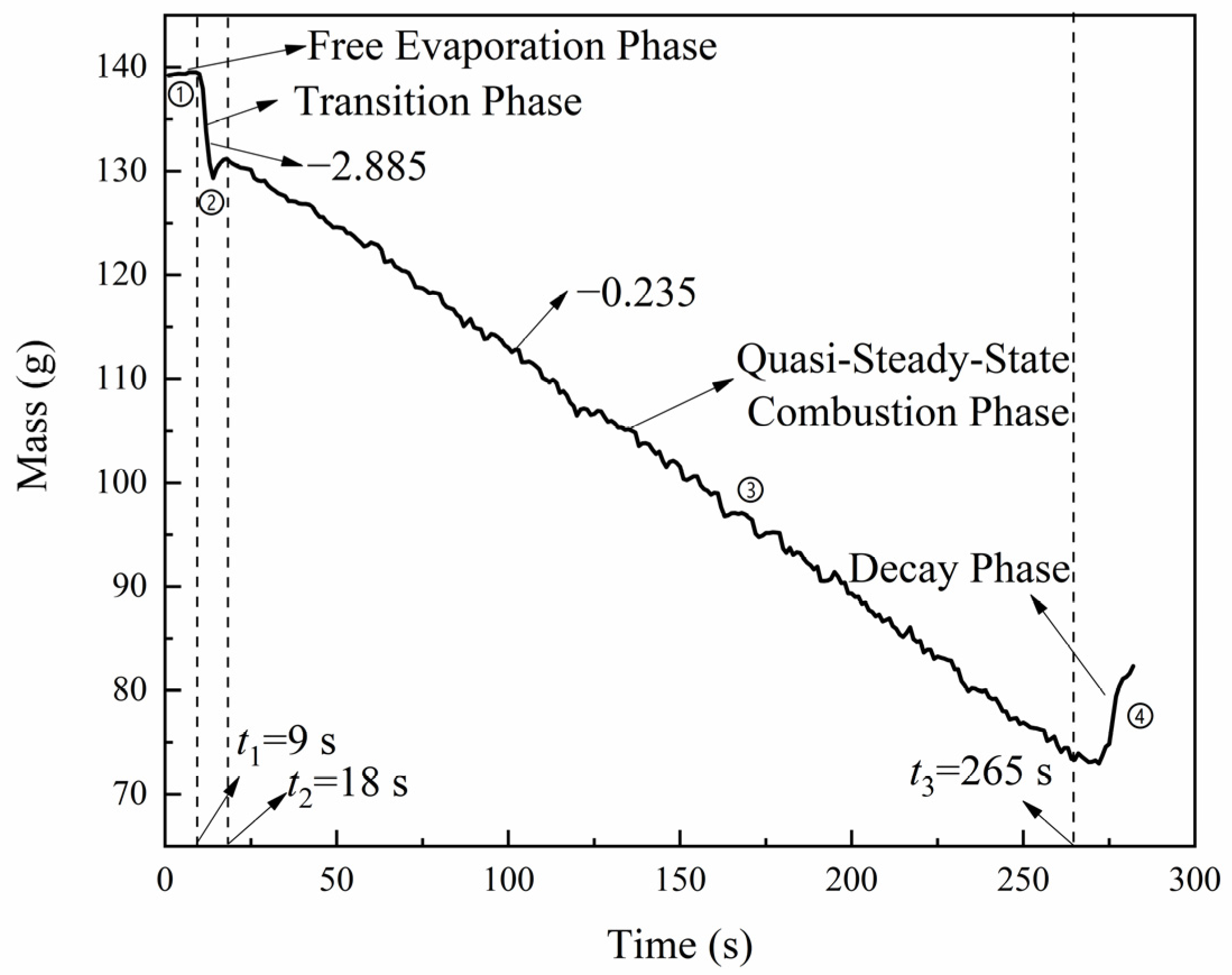
The burning rate is a crucial parameter in fire research. Figure 3 illustrates the curve of fuel mass changes over time under experimental conditions featuring a fuel pan diameter of 7.5 cm and an air-inlet width of 5 cm. Due to the brief intervals between experiments, the residual temperature inside the fire whirl generator remains high. This results in the rapid generation of a fire whirl in successive experiments, virtually eliminating the free combustion phase. Hence, based on the changes in mass, we can categorize the entire combustion process into the free evaporation phase, transition phase, quasi-steady-state combustion phase, and decay phase [27]. Linear fitting of the mass changes indicates that the transition phase and the quasi-steady-state combustion phase have mass loss rates of 2.885 g/s and 0.235 g/s, respectively.
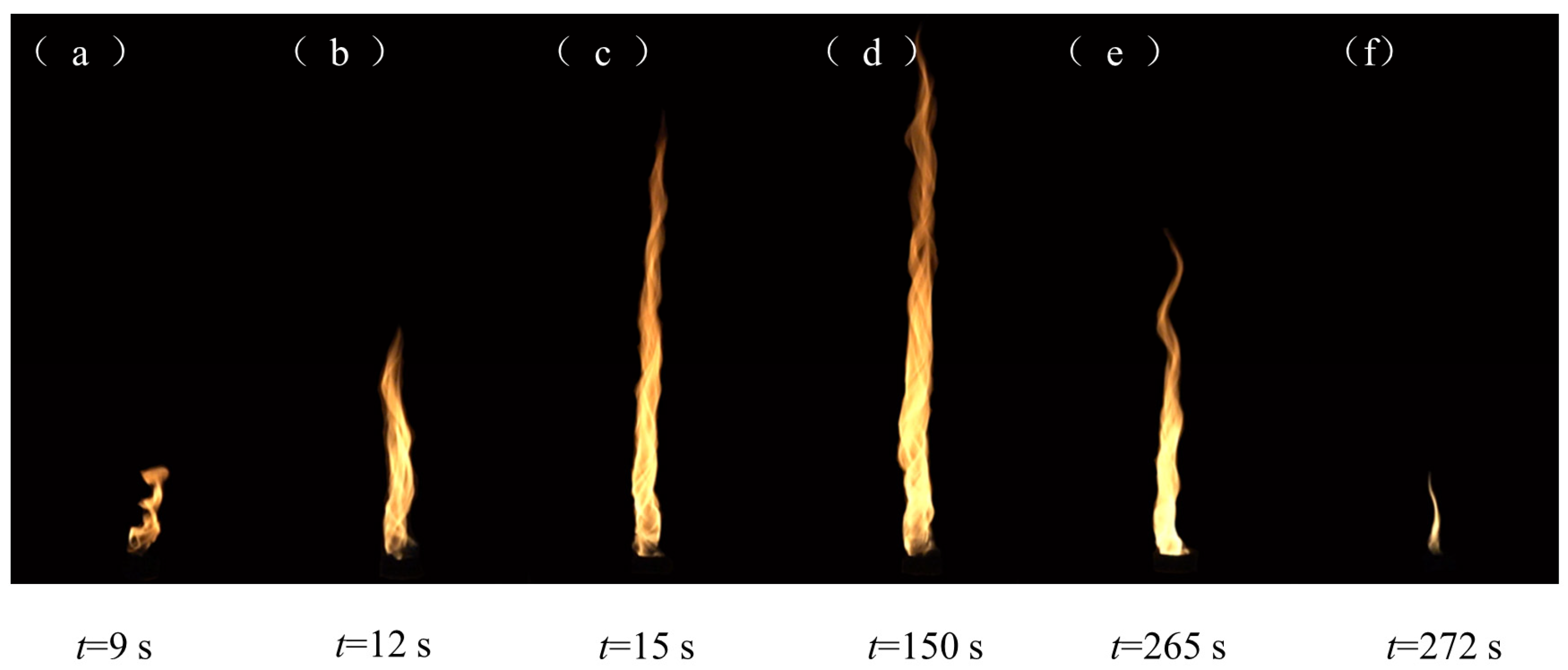
Figure 4 depicts the formation and evolution process of the fire whirl. During the free evaporation phase, the fuel remains unignited. In the transition phase, the initial flame shape and height essentially match those of a buoyant pool fire of the same dimensions, a phase often termed the brewing state. Over time, air entrainment causes air to flow in to the fire whirl generator from the air-inlet, fostering fluid convergence and increasing angular momentum. As a result, the flame consistently moves towards the center and quickly rises, ultimately forming a fire whirl. During the quasi-steady-state combustion phase, the fire whirl’s combustion tends towards stability, with the burning rate maintaining near constancy. In the decay phase, the fuel gradually exhausts. As the heat source vanishes, the negative pressure area above the fuel pan dissipates instantly. Consequently, the upward drag on the fuel pan is eliminated, rendering the mass measured by the electronic balance “overweight” [28].
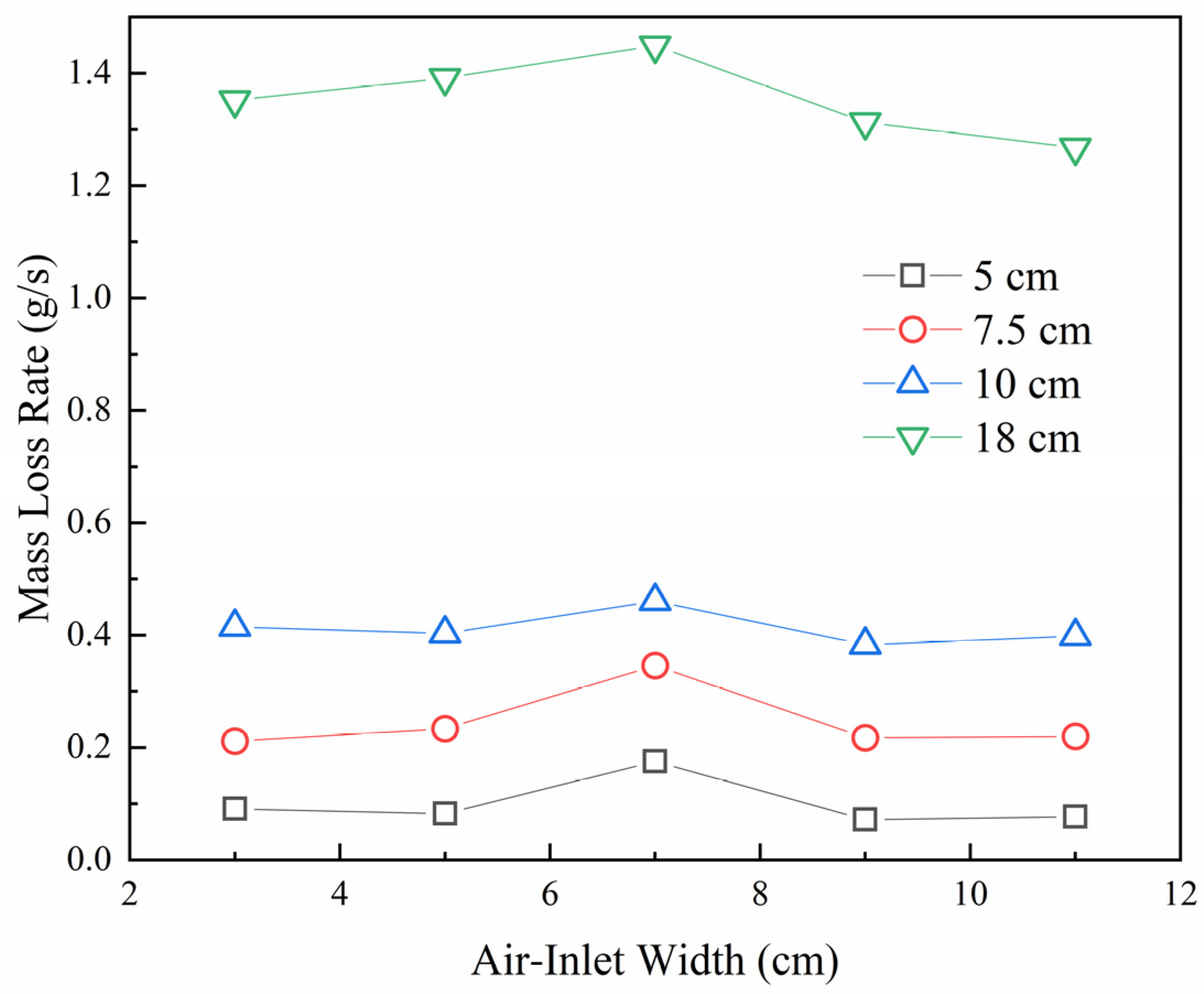
Figure 5 represents the curve of the fire whirl’s burning rates under varying fuel pan diameters as the air-inlet width changes. As illustrated in the figure, during the quasi-steady-state combustion phase, the fire whirl’s burning rate exhibits a positive correlation with the fuel pan’s diameter. As the air-inlet width enlarges, the fire whirl’s burning rate initially escalates and subsequently diminishes, peaking when the air-inlet width measures 7 cm.

3.3. Temperature Distribution

Temperature is a paramount parameter in fire research, playing a crucial role in assessing the fire source’s intensity, the amount of smoke produced, and the efficacy of fire extinguishing efforts [29]. High combustion temperatures may lead to substantial errors in thermocouple measurements, and these errors escalate with increasing thermocouple diameters. Thus, we implemented the method suggested by Lei et al. [15], which involves using two thermocouples of different diameters at the same measurement point. This method enables the measurement of the flame’s central axis temperature and helps correct any radiation errors in the results:
T = T 1 + T 2 T 1 1 T 2 4 T 4 T 1 4 T 4 D 2 D 1
where D 1 , D 2 are the diameters of the thermocouple junction (0.4 ± 0.02 mm and 2 ± 0.02 mm), T is the corrected actual flame temperature, T 1 is the temperature measured by the thick thermocouple, T 2 is the temperature measured by the thin thermocouple, and T is the environmental temperature, which in this experiment is 20 °C. Figure 6 presents both the measured and the corrected actual temperatures, recorded by the thermocouples during the fire whirl’s quasi-steady-state combustion phase. These measurements were taken 81.5 cm above the fuel pan’s top, with an air-inlet width of 5 cm and a fuel pan diameter of 18 cm.
Assuming uniform overall flame combustion, the flame shape can be determined by the fuel pan size, and the combustion power output does not rely on the fuel’s chemical properties [30,31,32]. The heat release rate can be calculated as follows:
Q ˙ = χ m ˙ Δ H c
where χ represents the combustion efficiency. For small fires, we take χ as 0.92 [33]. m ˙ is the mass loss rate of the fuel pan, and Δ H c is the combustion heat of the unit mass fuel. For n-heptane, Δ H c is 44.56 MJ/kg [34].
Similar to buoyant pool fires, fire whirls exhibit pronounced axial oscillation characteristics and comprise three zones: the continuous flame zone, the intermittent flame zone, and the plume zone. To anticipate the fire whirl flame’s behavior and identify the genuine starting point of the plume region, we introduce the concept of a virtual origin ( z 0 ) as a geometric function of the flame to refine the correlation. The formula to calculate the virtual origin reads as follows [35]:
z 0 = 0.083 Q ˙ 2 / 5 1.02 D
where z 0 is the height of the virtual origin above the top of the fuel pan, Q ˙ is the heat release rate, and D is the diameter of the fuel pan.
To investigate the central axis’s temperature distribution pattern during the fire whirl’s combustion process, we define parameters for excess temperature and dimensionless height:
Δ T = T T
where Δ T represents the excess temperature, T is the measured temperature, and T is the surrounding environmental temperature, and
Z = z / Q ˙ 2 / 5
where Z is the dimensionless flame height, z is the height of the thermocouple measurement point, and Q ˙ is the heat release rate.
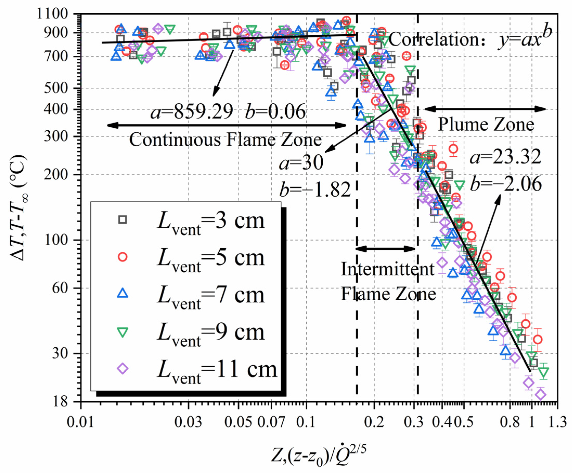
Figure 7 plots the curve correlating the central axis’s excess temperature with the variation in dimensionless flame height, demonstrating basic consistency with the classic McCaffrey model [36]. The ultimate expression for its temperature distribution is as follows:
T T = a z z 0 / Q ˙ 2 / 5 b
where a and b are both fitting parameters.
Within the continuous flame zone, the central axis’s excess temperature demonstrates a positive correlation with the 0.06th power of the standardized height ( Δ T Z 0.06 ). As the dimensionless flame height ascends, the fire whirl flame’s diameter gradually reduces, drawing the flame nearer to the central axis. At the continuous flame zone’s peak, the flame temperature culminates, approximating 900 °C. This peak temperature is higher than that of a buoyant pool fire (850 °C) [37], attributable to the fire whirl’s lower ratio of inhaled to required combustion air and lesser cold air, leading to a heightened peak flame temperature. Within both the intermittent flame and plume zones, the flame center axis’s excess temperature is inversely related to the dimensionless height, with power function indices of −1.82 and −2.06, respectively. Our findings exhibit slight deviations from the −1.75 and −3.55 obtained by Lei et al. [15], potentially due to scale effects. Given varying fuel pan diameters and air-inlet widths, the boundary line’s average value between the continuous and intermittent flame zones approximates 0.17, while between the intermittent flame zone and the plume flame zone, it is around 0.31. Our conclusion reveals that fire whirls display a proportion of continuous flames reaching up to 55%, exceeding the 40% observed in ordinary buoyant pool fires of equivalent size in our experiments.

3.4. Evolutionary Pattern of Flame Height

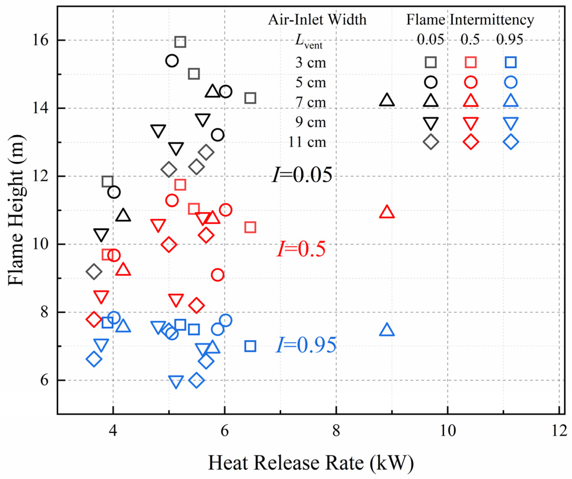
Figure 8 delineates the evolution pattern of the maximum, average, and continuous flame heights ( Z f , I = 0.05 , Z f , I = 0.5 , Z f , I = 0.95 ) in relation to the heat release rate under varied air-inlet widths. As depicted, the flame height correlates positively with the heat release rate and negatively with the air-inlet width, which is in line with its flame configuration.
To delve deeper into the changing relationship between heat release rate and flame height, we normalized the heat release rate [38].
Q ˙ * = Q · ρ c p T g 1 / 2 D 5 / 2
where Q ˙ * represents the dimensionless heat release rate, ρ represents the density of ambient air, c p represents the specific heat of air at constant pressure, T represents the surrounding environment temperature, g represents the acceleration of gravity, and D represents the diameter of the fuel pan.
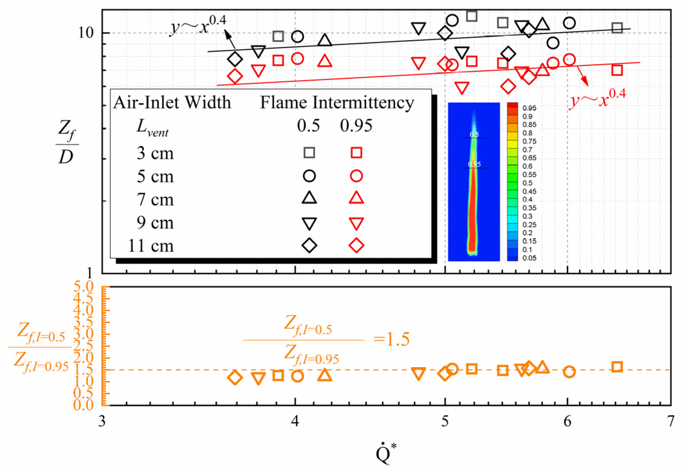
Figure 9 and Figure 10 illustrate the relationship between the fire whirl’s dimensionless flame heights (maximum, average, continuous), their corresponding ratios ( Z f , I = 00.05 / Z f , I = 0.5 , Z f , I = 0.5 / Z f , I = 0.95 ), and the dimensionless heat release rate. As can be seen from the figure:
  • These three dimensionless parameters of flame height (maximum, average, continuous) each have a power-law relationship with the dimensionless heat release rate ( Z f / D Q ˙ * 0.4 ), denoting the primary control mechanism of a three-dimensional axially symmetrical flame whirl [39,40]. This aligns with the correlation between flame height and heat release rate as proposed by Sun [41]. The distribution of the continuous and maximum flame heights near the fitting curve appears more discrete than the average flame height, potentially due to the flame’s periodic fluctuations, leading to certain measurement errors.
  • Considering different flame height ratios, the maximum-to-average flame height ratio is approximately 1.35 ( Z f , I = 0.05 / Z f , I = 0.5 = 1.35 ), and the average-to-continuous flame height ratio rounds to 1.5 ( Z f , I = 0.5 / Z f , I = 0.95 = 1.5 ). Both of these ratios remain unaffected by factors such as the air-inlet width, fuel pan diameter, ambient temperature, and the fire whirl’s heat release rate.

4. Conclusions

This research explored the influence of the air-inlet width and the diameter of the fuel pan on the combustion characteristics of fire whirls, employing a small-scale fixed-frame fire whirl generator for the experiments. The principal findings of the study are summarized below:
  • Fire whirl flame height exhibits a negative correlation with air-inlet width and a positive correlation with fuel pan diameter;
  • The entire combustion process of a fire whirl can be divided into four phases: free evaporation, transition, quasi-steady-state combustion, and decay. As the air-inlet width incrementally expands, the fire whirl’s burning rate in the quasi-steady-state combustion stage demonstrates an initial increase, followed by a decrease, peaking at an air-inlet width of 7 cm;
  • A fire whirl also consists of a continuous flame zone, an intermittent flame zone, and a plume zone, where the dimensionless flame height adheres to the corresponding power-law relationship with the excess temperature. The fire whirl’s continuous flames can comprise up to 55% of the total flames, a notable “stretch” compared to a buoyant pool fire of identical size;
  • The 2/5th power of the fire whirl’s dimensionless heat release rate maintains a positive correlation with the dimensionless flame height. The ratio of maximum to average flame height is approximately 1.35, and the ratio of average to continuous flame height is about 1.5. Both ratios remain unaffected by variables such as air-inlet width, fuel pan diameter, ambient temperature, and fire whirl combustion heat release rate.

Author Contributions

Conceptualization, L.H.; validation, Z.Y.; methodology, S.M.; investigation, Y.L.; resources, C.D.; writing—original draft preparation, L.H.; writing—review and editing, Y.J.; funding acquisition, C.D. All authors have read and agreed to the published version of the manuscript.

Funding

This research was funded by Anhui University Outstanding Youth Research Project under No. 2022AH020028 and No. 2022AH030037, Anhui Province Outstanding Young Talents Support Program under No. gxyqZD2022058, and the Project of Anhui Jianzhu University 2019 Talent Research Program under No. 2019QDZ21.The authors gratefully acknowledge these supports.

Institutional Review Board Statement

Not applicable.

Informed Consent Statement

Not applicable.

Data Availability Statement

Not applicable.

Conflicts of Interest

The authors declare no conflict of interest.

References

  1. Soma, S.; Saito, K. Reconstruction of Fire Whirls Using Scale Models. Combust. Flame 1991, 86, 269–284. [Google Scholar] [CrossRef]
  2. Tohidi, A.; Gollner, M.J.; Xiao, H. Fire Whirls. Annu. Rev. Fluid Mech. 2018, 50, 187–213. [Google Scholar] [CrossRef] [Green Version]
  3. Byram, G.M.; Martin, R. The Modeling of Fire Whirlwinds. For. Sci. 1970, 16, 386–399. [Google Scholar] [CrossRef]
  4. Emmons, H.W.; Ying, S.J. The Fire Whirl. Symp. (Int.) Combust. 1967, 11, 475–488. [Google Scholar] [CrossRef]
  5. Zhou, K.; Qin, X.; Zhang, L.; Wu, Y. An Experimental Study of Jet Fires in Rotating Flow Fields. Combust. Flame 2019, 210, 193–203. [Google Scholar] [CrossRef]
  6. Lei, J.; Liu, N.; Jiao, Y.; Zhang, S. Experimental Investigation on Flame Patterns of Buoyant Diffusion Flame in a Large Range of Imposed Circulations. Proc. Combust. Inst. 2017, 36, 3149–3156. [Google Scholar] [CrossRef]
  7. Liu, Z.; Liu, N.; Lei, J.; Miao, X.; Zhang, L.; Viegas, D.X. Evolution from Conical to Cylindrical Fire Whirl: An Experimental Study. Proc. Combust. Inst. 2021, 38, 4579–4586. [Google Scholar] [CrossRef]
  8. Ghodrat, M.; Shakeriaski, F.; Nelson, D.J.; Simeoni, A. Experimental and Numerical Analysis of Formation and Flame Precession of Fire Whirls: A Review. Fire 2021, 4, 43. [Google Scholar] [CrossRef]
  9. Byram, G.M.; Martin, R. Fire Whirlwinds in the Laboratory. Fire Control Notes 1962, 33, 13–17. [Google Scholar]
  10. Hassan, M.I.; Kuwana, K.; Saito, K.; Wang, F.J. Flow Structure of a Fixed-Frame Type Fire Whirl. Fire Saf. Sci. 2005, 8, 951–962. [Google Scholar] [CrossRef] [Green Version]
  11. Hayashi, Y.; Kuwana, K.; Dobashi, R. Influence of Vortex Structure on Fire Whirl Behavior. Fire Saf. Sci. 2011, 10, 671–679. [Google Scholar] [CrossRef]
  12. Kuwana, K.; Morishita, S.; Dobashi, R.; Chuah, K.H.; Saito, K. The Burning Rate’s Effect on the Flame Length of Weak Fire Whirls. Proc. Combust. Inst. 2011, 33, 2425–2432. [Google Scholar] [CrossRef]
  13. Satoh, K.; Yang, K.T. Experimental Observations of Swriling Fires. Proc. ASME Heat Transf. Div. 1996, 335, 393–397. [Google Scholar]
  14. Satoh, K.; Yang, K.T. Simulations of Swirling Fires Controlled by Channeled Self-Generated Entrainment Flows. Fire Saf. Sci. 1997, 5, 201–212. [Google Scholar] [CrossRef] [Green Version]
  15. Lei, J.; Liu, N.; Zhang, L.; Chen, H.; Shu, L.; Chen, P.; Deng, Z.; Zhu, J.; Satoh, K.; de Ris, J.L. Experimental Research on Combustion Dynamics of Medium-Scale Fire Whirl. Proc. Combust. Inst. 2011, 33, 2407–2415. [Google Scholar] [CrossRef]
  16. Lei, J.; Liu, N.; Tu, R. Flame Height of Turbulent Fire Whirls: A Model Study by Concept of Turbulence Suppression. Proc. Combust. Inst. 2017, 36, 3131–3138. [Google Scholar] [CrossRef]
  17. Lei, J.; Ji, C.; Liu, N.; Zhang, L. Effect of Imposed Circulation on Temperature and Velocity in General Fire Whirl: An Experimental Investigation. Proc. Combust. Inst. 2019, 37, 4295–4302. [Google Scholar] [CrossRef]
  18. Lei, J.; Miao, X.; Liu, Z.; Liu, N.; Zhang, L. Lifted Flame in Fire Whirl: An Experimental Investigation. Proc. Combust. Inst. 2021, 38, 4595–4603. [Google Scholar] [CrossRef]
  19. Lei, J.; Huang, P.; Liu, N.; Zhang, L. On the Flame Width of Turbulent Fire Whirls. Combust. Flame 2022, 244, 112285. [Google Scholar] [CrossRef]
  20. Chuah, K.H.; Kuwana, K.; Saito, K.; Williams, F.A. Inclined Fire Whirls. Proc. Combust. Inst. 2011, 33, 2417–2424. [Google Scholar] [CrossRef]
  21. Yu, D.; Zhang, P. On Flame Height of Circulation-Controlled Firewhirls with Variable Physical Properties and in Power-Law Vortices: A Mass-Diffusivity-Ratio Model Correction. Combust. Flame 2017, 182, 36–47. [Google Scholar] [CrossRef]
  22. Yu, D.; Zhang, P. On the Flame Height of Circulation-Controlled Firewhirls with Variable Density. Proc. Combust. Inst. 2017, 36, 3097–3104. [Google Scholar] [CrossRef]
  23. Yu, H.; Guo, S.; Peng, M.; Li, Q.; Ruan, J.; Wan, W.; Chen, C. Study on the Influence of Air-Inlet Width on Fire Whirls Combustion Characteristic. Procedia Eng. 2013, 62, 813–820. [Google Scholar] [CrossRef] [Green Version]
  24. Zhang, X.; Hu, L.; Wu, L.; Kostiuk, L.W. Flame Radiation Emission from Pool Fires under the Influence of Cross Airflow and Ambient Pressure. Combust. Flame 2019, 202, 243–251. [Google Scholar] [CrossRef]
  25. Zhen, H.S.; Leung, C.W.; Cheung, C.S. Thermal and emission characteristics of a turbulent swirling inverse diffusion flame. Int. J. Heat Mass Tran. 2010, 53, 902–909. [Google Scholar] [CrossRef]
  26. Dong, L.L.; Cheung, C.S.; Leung, C.W. Heat transfer characteristics of an impinging swirling inverse diffusion butane/air flame jet. Exp. Therm. Fluid Sci. 2021, 128, 110438. [Google Scholar] [CrossRef]
  27. Wang, P.F. Researches on the Flame and Flow Characteristics of Fire Whirls. Ph.D. Thesis, University of Science and Technology of China, Hefei, China, 2015. [Google Scholar]
  28. Lei, J. Experimental and Theoretical Researches on the Combustion Dynamics of Fire Whirls. Ph.D. Thesis, University of Science and Technology of China, Hefei, China, 2012. [Google Scholar]
  29. Li, J.; Zeng, Y.; Tao, L.; Liu, Z.; Li, B. Experimental Study on Temperature Decay and Smoke Control in Tunnel Fires with Combination of Multi-Point Smoke Exhaust and Longitudinal Ventilation. Int. J. Therm. Sci. 2023, 183, 107847. [Google Scholar] [CrossRef]
  30. Orloff, L.; De Ris, J. Froude Modeling of Pool Fires. Symp. (Int.) Combust. 1982, 19, 885–895. [Google Scholar] [CrossRef]
  31. Quintiere, J.G.; Grove, B.S. A Unified Analysis for Fire Plumes. Symp. (Int.) Combust. 1998, 27, 2757–2766. [Google Scholar] [CrossRef]
  32. Wan, H.; Gao, Z.; Ji, J.; Wang, L.; Zhang, Y. Experimental Study on Merging Behaviors of Two Identical Buoyant Diffusion Flames under an Unconfined Ceiling with Varying Heights. Proc. Combust. Inst. 2019, 37, 3899–3907. [Google Scholar] [CrossRef]
  33. Lönnermark, A.; Ingason, H. The Effect of Cross-Sectional Area and Air Velocity on the Conditions in a Tunnel during a Fire; SP Technology Research Institute of Sweden: Borås, Sweden, 2007. [Google Scholar]
  34. Ji, J.; Wan, H.; Gao, Z.; Fu, Y.; Sun, J.; Zhang, Y.; Li, K.; Hostikka, S. Experimental Study on Flame Merging Behaviors from Two Pool Fires along the Longitudinal Centerline of Model Tunnel with Natural Ventilation. Combust. Flame 2016, 173, 307–318. [Google Scholar] [CrossRef]
  35. Heskestad, G. Fire Plumes, Flame Height, and Air Entrainment. In SFPE Handbook of Fire Protection Engineering; Springer: Berlin/Heidelberg, Germany, 2016; pp. 396–428. [Google Scholar]
  36. Mccaffrey, B.J. Purely Buoyant Diffusion Flames: Some Experimental Results; Center for Fire Research National Engineering Laboratory National Bureau of Standards: Washington, DC, USA, 1979. [Google Scholar]
  37. Lei, J.; Liu, N.; Zhang, L.; Satoh, K. Temperature, Velocity and Air Entrainment of Fire Whirl Plume: A Comprehensive Experimental Investigation. Combust. Flame 2015, 162, 745–758. [Google Scholar] [CrossRef]
  38. Zukoski, E.E.; Cetegen, B.M.; Kubota, T. Visible Structure of Buoyant Diffusion Flames. Symp. (Int.) Combust. 1985, 20, 361–366. [Google Scholar] [CrossRef]
  39. Lee, Y.P. Heat Fluxes and Flame Heights on External Facades from Enclosure Fires. Ph.D. Thesis, University of Ulster, Belfast, UK, 2006. [Google Scholar]
  40. Tang, F.; Hu, L.H.; Delichatsios, M.A.; Lu, K.H.; Zhu, W. Experimental Study on Flame Height and Temperature Profile of Buoyant Window Spill Plume from an Under-Ventilated Compartment Fire. Int. J. Heat Mass Transf. 2012, 55, 93–101. [Google Scholar] [CrossRef]
  41. Sun, X.; Hu, L.; Zhang, X.; Ren, F.; Yang, Y.; Fang, X. Experimental Study on Flame Pulsation Behavior of External Venting Facade Fire Ejected from Opening of a Compartment. Proc. Combust. Inst. 2021, 38, 4485–4493. [Google Scholar] [CrossRef]
Figure 1. Schematic diagram of the experimental design.
Fire 06 00309 g001
Figure 2. Profiles and images of intermittent flames for varied air-inlet widths and fuel pan diameters.
Fire 06 00309 g002
Figure 3. Mass vs. time (D = 7.5 cm, Lvent = 5 cm).
Fire 06 00309 g003
Figure 4. The formation and development of the fire whirl.
Fire 06 00309 g004
Figure 5. Mass loss rate vs. air-inlet widths.
Fire 06 00309 g005
Figure 6. Diagram representing the measured and calibrated temperatures from the thermocouple pairs during the quasi-steady-state combustion phase.
Fire 06 00309 g006
Figure 7. ( T T ) vs. z z 0 / Q ˙ 2 / 5 .
Fire 06 00309 g007
Figure 8. Variation of (maximum-( I = 0.05), mean-( I = 0.5), continuous-( I = 0.95)) flame height ( Z f ) with HRR ( Q ˙ ).
Fire 06 00309 g008
Figure 9. Normalized flame height ( Z f / D ) as well as the ratio of maximum flame height ( I = 0.05 in black symbols) to mean flame height ( I = 0.5 in red symbols) ( Z f , I = 0.05 / Z f , I = 0.5 in blue symbols) against non-dimensional HRR ( Q ˙ * ).
Fire 06 00309 g009
Figure 10. Normalized flame height ( Z f / D ) as well as the ratio of mean flame height ( I = 0.5 in black symbols) to continuous flame height ( I = 0.95 in red symbols) ( Z f , I = 0.5 / Z f , I = 0.95 in orange symbols) against non-dimensional HRR ( Q ˙ * ).
Fire 06 00309 g010
Table 1. Summary of test conditions.
LventD Q ˙ Q ˙ * Z f , I = 0.05 Z f , I = 0.5 Z f , I = 0.95
(cm)(cm)(kW) (m)(m)(m)
353.736.460.720.530.32
7.58.685.451.130.830.56
1017.015.201.601.180.76
1855.433.902.131.751.39
553.395.870.660.460.22
7.59.586.021.090.830.58
1016.535.051.541.130.74
1857.044.012.081.741.41
757.2012.450.650.450.26
7.514.198.911.070.820.56
1018.905.781.451.070.69
1859.414.181.951.661.36
952.965.130.640.420.18
7.58.935.611.030.810.52
1015.724.811.341.060.76
1853.823.791.861.531.27
1153.185.490.610.410.20
7.59.035.670.950.770.49
1016.355.001.221.000.75
1851.963.661.661.401.19
Disclaimer/Publisher’s Note: The statements, opinions and data contained in all publications are solely those of the individual author(s) and contributor(s) and not of MDPI and/or the editor(s). MDPI and/or the editor(s) disclaim responsibility for any injury to people or property resulting from any ideas, methods, instructions or products referred to in the content.